
 Open Access Article
 This Open Access Article is licensed under a
 Creative Commons Attribution 3.0 Unported Licence
Recent progress in ammonia fuel cells and their potential applications
Georgina
Jeerh
a,
Mengfei
Zhang
 a and
Shanwen
Tao
*ab
a and
Shanwen
Tao
*ab
aSchool of Engineering, University of Warwick, Coventry CV4 7AL, UK
bDepartment of Chemical Engineering, Monash University, Clayton, Victoria 3800, Australia
First published on 26th November 2020
Abstract
Conventional technologies are largely powered by fossil fuel exploitation and have ultimately led to extensive environmental concerns. Hydrogen is an excellent carbon-free energy carrier, but its storage and long-distance transportation remain big challenges. Ammonia, however, is a promising indirect hydrogen storage medium that has well-established storage and transportation links to make it an accessible fuel source. Moreover, the notion of ‘green ammonia’ synthesised from renewable energy sources is an emerging topic that may open significant markets and provide a pathway to decarbonise a variety of applications reliant on fossil fuels. Herein, a comparative study based on the chosen design, working principles, advantages and disadvantages of direct ammonia fuel cells is summarised. This work aims to review the most recent advances in ammonia fuel cells and demonstrates how close this technology type is to integration with future applications. At present, several challenges such as material selection, NOx formation, CO2 tolerance, limited power densities and long term stability must still be overcome and are also addressed within the contents of this review.
 Georgina Jeerh | Georgina Jeerh received her MChem degree from the School of Chemistry, University of Southampton in 2018. She is currently a PhD student under the supervision of Professor Shanwen Tao in the School of Engineering, University of Warwick. Her research mainly focuses on the synthesis and design of electrodes within ammonia-fed fuel cells for clean energy applications. |
 Mengfei Zhang | Mengfei Zhang received his bachelor's (2012) and master's (2015) degrees from the China University of Geosciences (Wuhan). He obtained his PhD degree in materials science and engineering from Tsinghua University in 2019. Now, he is a research fellow at the School of Engineering, University of Warwick, UK. His current research is focused on the design and synthesis of nanostructured materials for different energy applications in fuel cells and electrochemical synthesis. |
 Shanwen Tao | Shanwen Tao is Professor of Chemical Engineering & Sustainable Processes in the School of Engineering, University of Warwick. His research interests include new ionic/electronic conducting materials for electrochemical devices such as fuel cells, electrolysers, batteries and super-capacitors. He is also interested in new catalysts for synthesis of ammonia and wastewater treatment through electrochemical processes. |
1. Introduction
Energy forms a significant portion of our economic and social sector. It is a powerful resource directly related to development and standards of living. A constant growth in global population has meant that energy demands have continued to grow, evidenced by the 2.3% increase in global total energy consumption during 2018 compared to that during the previous year. The supply of such energy is primarily delivered through fossil fuel exploitation, making up 81% of the mainstream energy supply in 2018.1 The means of such exploitation has triggered mass environmental concerns with increased emissions of atmospheric pollutants such as CO2 and NOx.2 Suitable management of energy demands whilst simultaneously combating climate change is therefore an increasingly important discussion point within today's society.Several renewable energy sources have been proposed with the potential to replace conventional routes of energy generation.3 Such renewable sources like wind and solar power for example are considered clean technologies.4 However, these sources are often regarded as unreliable as they are intermittent in nature, relying heavily on external geological factors such as altitude, wind speed and UV exposure.5 Subsequently, there is great motivation to replace existing technology with clean, reliable alternatives. Amongst such technologies, fuel cells have been proposed as energy conversion devices that convert chemical energy in external fuels to electricity through a series of electrochemical reactions. They are often recommended due to their high efficiency and low environmental footprint upon use.3
1.1. Hydrogen as a carbon-free energy carrier
Hydrogen is often regarded as the primary choice of fuel in fuel cells. The development of fuel has followed the path of increasing hydrogen amount, from coal to petroleum to natural gas. Reaching a state of pure hydrogen is therefore a systematic direction for fuel evolution.6 Hydrogen fuel cells are considered clean technology since they have a less polluting nature and produce water, an environmentally benign product.7,8 Moreover, the chemical energy within hydrogen may be stored for prolonged periods of time, making it ideal to combine with intermittent renewable energy during phases of low energy production.9Although hydrogen is a promising candidate for clean energy generation, there are several hurdles which must be acknowledged. Two of the major challenges involve the storage and transportation of hydrogen.10 This has proven to be difficult, with little or no infrastructure for the effective transportation of hydrogen, and such networks require substantial amounts of money to establish. Additionally, the storage of hydrogen is a major challenge in the progression towards a hydrogen economy. It is commonly stored using the following methods: (a) compression, (b) liquefaction and (c) chemical or physical combination with materials like metal or complex hydrides and carbon materials as a solid fuel.11–14 Each of these have limitations associated with efficient on-board hydrogen storage, for example, the requirement of storage volume tanks, specifically insulated cryogenic tanks and refrigeration units that can increase the weight and cost of storage.15–18
1.2. Alternatives to hydrogen
To tackle the difficulties related to hydrogen and truly value the concept of a hydrogen economy, hydrogen carriers have been suggested. These involve ethanol and methanol as indirect hydrogen storage media to generate electricity. The first direct methanol fuel cell was described by Justi and Winsel in 1955 and the properties of methanol have since been studied for more than several decades due to its low cost and reactivity.19,20 Ethanol has also gained attention as a less toxic, readily available alcohol alternative to methanol for use within fuel cells.21 Nevertheless, these organic-based fuels contain carbon and so will release CO2 upon utilisation. Their indirect use in hydrogen proton exchange membrane fuel cells (PEMFCs) would therefore require the presence of a steam reformer in order to abstract hydrogen from the carbon source and a carbon capture and storage unit, which would contribute weight, additional space and cost.11 This has driven progress towards the use of nitrogen-based fuels like ammonia and hydrazine as carbon-free indirect hydrogen storage media.22,23 Ammonia contains 17.6 wt% hydrogen and, unlike ethanol and methanol, contains no carbon and therefore will not release CO2 on decomposition.23,24 For comparison, a range of hydrogen and ammonia fuel characteristics are illustrated in Table 1.| Fuel | Temperature [°C] | Pressure [MPa] | Weight [% H2] | Energy density [MJ L−1] | Flammability range | Relative cost |
|---|---|---|---|---|---|---|
| Compressed hydrogen | 25 | 35 | 100 | 2.76 | 4–74 | High |
| 70 | 5.60 | |||||
| Liquid hydrogen | −235 | 0.1 | 100 | 8.6 | 4–74 | High |
| Liquid ammonia | 25 | 1 | 17.6 | 12.9 | 16–25 | Low |
Ammonia can be used as an emission-less energy vector where it may be converted to hydrogen. A recent publication on producing high-purity hydrogen by electrolysis of ammonia at an intermediate temperature of 250 °C has been demonstrated. Lim et al. made use of a solid acid-based electrochemical cell (SAEC), where Cs-promoted Ru on carbon nanotubes (Ru/CNT) acted as a thermal decomposition catalyst and Pt on carbon black mixed with CsH2PO4 was used to catalyse hydrogen electrooxidation.29 Further to this, the electrocatalytic oxidation of ammonia provides a potential solution for on-board hydrogen supply for a fuel-cell vehicle. Huang et al. recently reported a nanostructured catalyst of Cu2O wire-in-Ni(OH)2 plate passivated by a thin CuO surface to stably electrolyse ammonia solution to hydrogen and nitrogen at a current density of 80 mA cm−2 at 25 °C.30 Alternatively, ammonia may be utilised directly in ammonia fuel cells, in an internal combustion engine or a gas turbine.31 Ezzat and Dincer proposed a route whereby an internal combustion engine to power a vehicle can be fuelled using both ammonia and hydrogen (from the dissociation of ammonia). It was found that the overall energy efficiency of the system was around 61.89%.32 Direct ammonia fuel cells are an important emerging technology that can be used to extract the chemical energy within ammonia and convert such into electricity at high efficiency.
The potential of ammonia as a hydrogen carrier has more recently been recognised through the concept of green ammonia.23,33 As the transition from fossil fuels to renewable energy becomes more prominent, companies such as BP who are heavily involved as oil and gas majors have included green ammonia within their portfolio of clean energy technology. In May 2020, BP Australia announced the management of a feasibility study in Geraldton to establish a route for the full integration of a green supply chain by 2021. The pilot-scale involves a 20![[thin space (1/6-em)]](https://www.rsc.org/images/entities/char_2009.gif) 000 ton/year green ammonia plant distributing to domestic markets and could amount up to 1000000 ton per year (1.5 GW capacity).34 This opens up significant new markets and provides a pathway to decarbonise an array of products that may be reliant on fossil fuels. Applications of green ammonia are demonstrated in Fig. 1.
000 ton/year green ammonia plant distributing to domestic markets and could amount up to 1000000 ton per year (1.5 GW capacity).34 This opens up significant new markets and provides a pathway to decarbonise an array of products that may be reliant on fossil fuels. Applications of green ammonia are demonstrated in Fig. 1.
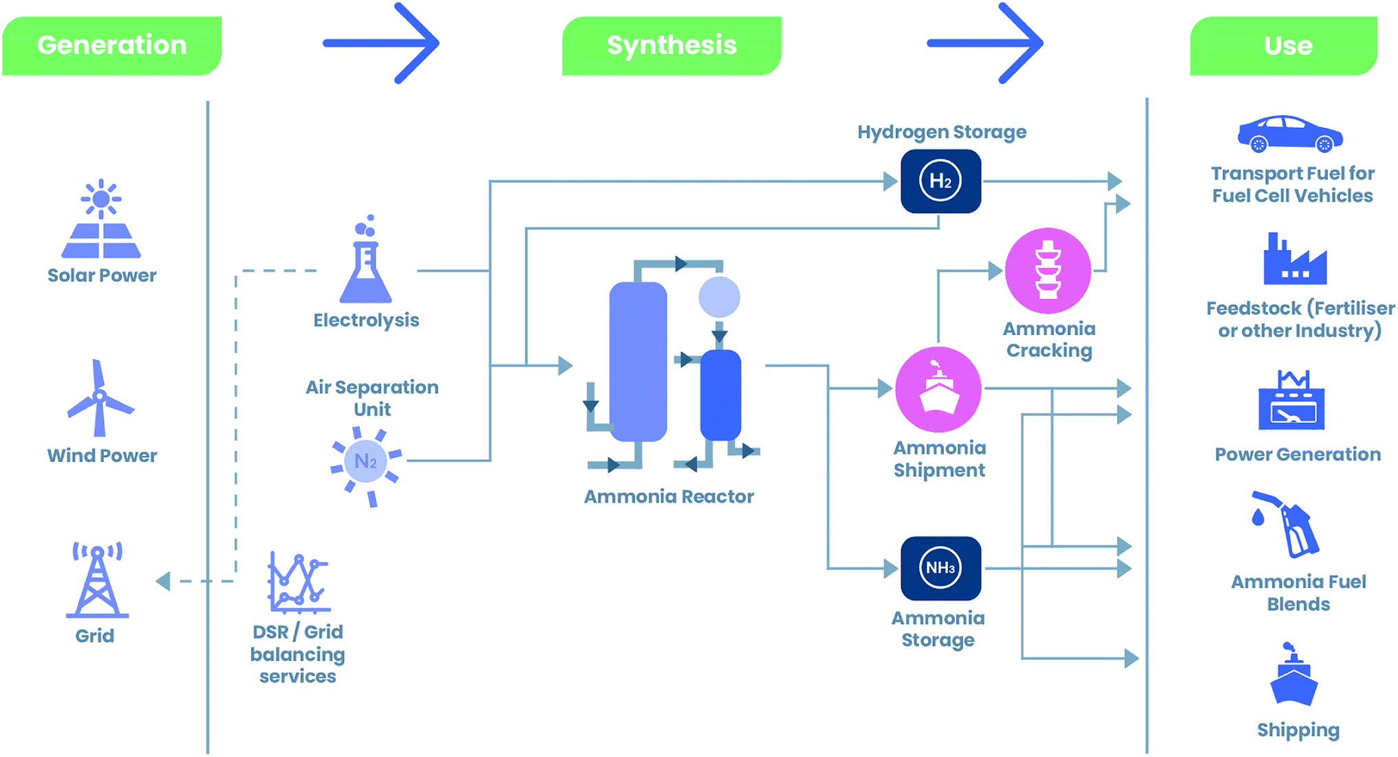 | ||
| Fig. 1 Landscape of green ammonia illustrating renewable synthesis of ammonia from generation sources and the variety of end uses.35 | ||
Production of green ammonia has been demonstrated by various other countries world-wide. As of July 2020, Spain announced plans to produce green ammonia for emission-free fertilisers and hopes to reduce its natural gas use by over 10% as well as producing green ammonia by early 2021.36 Eneus Energy also recently announced its plans to build a green ammonia plant in Orkney, Scotland. The project emphasises on producing 11 tonne per day of green ammonia where the plant is powered by two wind turbines to provide the region with a scalable solution for renewable energy storage that does not rely on grid transmission.37 Furthermore, Saudi Arabia has announced a $5 billion investment in a 4 GW green ammonia plant to be operational by 2025. The intention is to globally supply green ammonia and decompose it to hydrogen at the point of use to supply hydrogen refuelling stations.38 With the emerging green ammonia industry, matching technologies are desired to recover the stored energy in green ammonia, such as direct ammonia fuel cells.
1.3. Organisation of the review
Ammonia fuel cells can be considered either direct or indirect, depending on where the decomposition of ammonia occurs. Indirect ammonia fuel cells involve thermally decomposing ammonia to release hydrogen. The method of ammonia decomposition for on-site generation of hydrogen for fuel cells has been widely proposed and reviewed.39,40 Direct ammonia fuel cells, however, reap the benefits of using ammonia directly within the fuel cell and truly utilise the chemical energy stored within ammonia itself. This eliminates the necessity of on-board hydrogen storage and bypasses the decomposition step. This leads to savings in facility and operating costs, improving the overall efficiency.5,23,41–44 This review will therefore focus on direct ammonia fuel cells. Ammonia fuel cells can be categorised according to different criteria including electrolyte, temperature, and reactant-based and ion transfer-based classifications.45 Within this review, we focus on direct ammonia fuel cells to convert the chemical energy in ammonia into electricity and classify the technology based on electrolyte type as follows:• Oxygen anion conducting electrolyte-based solid oxide fuel cells (SOFC-O)
• Proton conducting electrolyte-based solid oxide fuel cells (SOFC-H)
• Alkaline ammonia fuel cells (AAFCs) (including molten alkaline ammonia fuel cells)
• Alkaline membrane-based fuel cells (AMFCs)
• Microbial ammonia fuel cells
Previous reviews have focused on a variety of ammonia fuel cells with various electrolyte materials, electrocatalyst materials and operating temperatures.3,5,41,44,46,47 However, it is important to analyse the conditions that provide the most up-to-date optimum performances. It is also equally important to assess the prospects of such fuel cell technology within real life applications and their ability to integrate with and potentially replace existing technologies. Section 2 provides a brief introduction into SOFC-O, SOFC-H and AMFC technology and assesses each based on the effect of the electrolyte material, electrocatalyst material and effect of operating temperature within each system. A comprehensive study on performances based on recent literature is presented. AAFCs and microbial ammonia fuel cells are also mentioned for completeness. Section 3 more closely discusses the potential integration of these technologies into real life systems. We evaluate the likelihood of each technology type for the next generation of ammonia fuel cells. Section 4 provides comments for prospective and current challenges of today's direct ammonia fuel cell technologies.
2. Ammonia
2.1. Ammonia synthesis
The manufacture of ammonia is already well established, with a global production of 180 million tons being reported in 2015.48,49 This is mainly owing to its vast use as a fertilizer as well as a precursor for chemical synthesis and industrial refrigerants.23,50Currently, large-scale production of ammonia is typically carried out via the Haber–Bosch (H–B) process.51,52
| 3H2(g) + N2(g) ⇌ 2NH3(g), ΔH° = −92 kJ mol−1 | (1) |
From a thermodynamic perspective, this reaction is favourable at room temperature and has a Gibbs free energy value of −32.9 kJ per mol N2.51,53 The reaction, however, endures a large kinetic barrier associated with the strong covalent N![[triple bond, length as m-dash]](https://www.rsc.org/images/entities/char_e002.gif) N bond. The presence of a catalyst and excessively high temperatures are therefore required.51,54 The H–B process typically operates at temperatures ranging from 325–525 °C and high pressures ranging from approximately 150–350 atm in a reactor with an iron-based catalyst to produce ammonia at a yield of around 10–20%.23,44 These conditions have high-energy costs associated with them and potential safety issues.51
N bond. The presence of a catalyst and excessively high temperatures are therefore required.51,54 The H–B process typically operates at temperatures ranging from 325–525 °C and high pressures ranging from approximately 150–350 atm in a reactor with an iron-based catalyst to produce ammonia at a yield of around 10–20%.23,44 These conditions have high-energy costs associated with them and potential safety issues.51
During the H–B process, ammonia is synthesised from its basic elements, hydrogen and nitrogen. Although the latter can easily be obtained from the abundancy of nitrogen within the atmosphere, the origin of hydrogen remains a crucial challenge.55–59 A conventional H–B plant converts natural gases like methane or liquefied petroleum gases like propane into hydrogen gas through steam reformation; this is then mixed with nitrogen gas from the air to produce ammonia.51 It is important to realise that even though the use of ammonia itself is carbon free, the production process releases carbon dioxide as a by-product of fossil fuel exploitation.44 A clean, large-scale synthesis route for ammonia at reduced temperature and pressure is therefore of particular interest. A recent publication by Fernandez et al. has addressed such issues by detailing opportunities for intermediate temperature renewable ammonia synthesis.60
Furthermore, alternative routes for clean ammonia synthesis have been proposed.61 As suggested by Siemens, green ammonia is significant in meeting the challenges of the 21st century. By synthesising ammonia through renewable methods, CO2 savings of over 360000000 tonne per year world-wide could be made. Siemens has demonstrated a network of technologies that combines hydrogen, supplied through water electrolysis, and nitrogen, extracted from air, in the Haber–Bosch process to synthesise ammonia.62
The roadmap to clean and sustainable ammonia production requires finding novel methods.63 Electrochemical synthesis for clean ammonia has been extensively reviewed.63–69 The nitrogen electrochemical reduction reaction (NRR) to produce ammonia under ambient conditions can offer an alternative to the H–B process and can produce ammonia via renewable energy.70 The reactants are derived from nitrogen and water, which are naturally abundant. For example, Han et al. reported an electrocatalytic ammonia synthesis system with air as the nitrogen source, which was shown to be self-powered, eco-friendly, low-cost, facilely fabricated and scaleable.71 Often, a major drawback of such a process is finding a material that can assist the NRR, as catalysts tend to show low activity and selectivity due to the competing hydrogen evolution reaction (HER) and water reduction reaction. Catalysts must be designed to optimise mass transport, chemisorption and transduction pathways of protons and electrons.72 For example, Ampelli recently reported a gas diffusion electrode on stainless steel which successfully overcame the gas transportation limitations for high current ammonia electrosynthesis.73 Furthermore, Du et al. recently presented an FeS2 catalyst with superior catalytic performance to achieve a high ammonia yield, high stability and selectivity. Oxygen vacant TiO2 catalysts grown on Ti3C2Tx nanosheets were found to exhibit an ammonia yield faradaic efficiency of 16.07%, placing it as one of the most promising NRR electrocatalysts.74 A series of perovskite materials have also been recently proposed as low costing ammonia synthesis catalysts.59,75–78 In this article, we will focus on direct ammonia fuel cell technologies.
2.2. Ammonia safety
Safety in regard to ammonia utilisation must also be addressed if considering ammonia as a fuel for a wide range of applications for public use.Ammonia can be dissolved in water to give a solution with a solubility limit of approximately 35 wt% that does not require any specialised storage equipment and can simply be stored in a glass bottle.23 Ammonia can be compressed into the liquid state at a pressure of 8 bar and temperature of 20 °C, which is much easier than that of hydrogen. It is deemed corrosive by nature, with the ability to cause dehydration, severe skin burns, frostbite and eye damage.79 On inhalation, ammonia can cause lung damage or respiratory failure at vapour concentrations of 1700 ppm and can also lead to fatality if inhaled at excessively high concentrations of 5000 ppm.3 The use of ammonia may therefore be monitored under safety regulations and the toxicity issue can be addressed with appropriate practice. Ammonia can be stored as a solid in metal–amine complexes such as copper, zinc and their alloys to alleviate the corrosive properties.80 It can also be stored in compounds such as urea, which is a non-toxic solid, to overcome the issue of toxicity associated with liquid and gaseous ammonia.23 Storing in the solid form also allows for ease of transportation and avoids leakage.3 These solids can then emit ammonia upon heating or exposure to a vacuum. Further to this, unlike that of hydrogen, the smell of ammonia is easily detected at concentrations as low as 1 ppm due to its sharp and irritating odour.81
2.3. Direct ammonia SOFCs
SOFCs are often regarded as the most efficient method for power generation and are one of the most commonly studied types of ammonia-fed fuel cell technology.43,82 This type of fuel cell demonstrates high energy conversion efficiency and a high degree of fuel flexibility. Within these systems, ammonia is cracked at elevated temperatures traditionally ranging between 500 and 1000 °C. An advantage of using such elevated temperatures is that the cracking of ammonia and the electricity generation process can effectively be merged. Ammonia can therefore be directly fed into SOFCs, eliminating any pre-treatment requirement.81,83 High temperature also alleviates the cost and requirement of a separate ammonia cracking unit and increases the ionic conductivity so ohmic loss at the electrolyte can be minimised.43The first direct ammonia SOFC was reported by Vayenas and Farr in 1980, with the aim of harvesting NO as a chemical feedstock as well as simultaneously producing electricity.84 The fuel cell consisted of a Y2O3-stabilised ZrO2 zirconia (YSZ) electrolyte and Pt electrodes. The electrochemical reactions that took place on the anode are as follows:
| 2NH3 + 5O2− → 2NO + 3H2O + 10e− | (2) |
| 2NH3 + 3NO → 5/2N2 + 3H2O | (3) |
Due to the slow diffusion of oxygen anions through the electrolyte, eqn (2) is the rate-limiting step and consequently the NO content can exceed 60%. Although the aim of the above experiment was to produce both NO and electricity, the formation of NO is undesirable when the fuel cell is solely used for electricity generation purposes.84 The development of SOFC technology has therefore shifted towards the production of N2 as the sole nitrogen containing compound.
SOFCs can be sorted into two categories in accordance with the type of electrolyte that is used: oxygen anion conducting electrolyte-based SOFCs (SOFC-O) and proton conducting electrolyte-based SOFCs (SOFC-H).5
| Anode: H2 + O2− → H2O + 2e− | (4) |
| Cathode: 1/2O2 + 2e− → O2− | (5) |
 | ||
| Fig. 2 Schematic illustration of ammonia-fed SOFC-O. | ||
Water is present at the anode along with ammonia fuel and so there is a possibility of NOx formation according to eqn (2). Given that a suitable catalyst is employed, the formation of NO is supressed and assumed to be negligible, but the presence of nitrogen gas may reach high concentrations depending on the temperature and pressure used. This in turn can affect the thermodynamic equilibrium of ammonia decomposition, dilute the in situ generated hydrogen and decrease the reversible cell potential of the fuel cell.3
Along with the inherent properties of the materials used, it is important to note that external properties such as the thickness of the electrolyte can also affect cell performance. The internal resistance of an SOFC will decrease when utilizing a thinner electrolyte. However, reducing the thickness of the electrolyte too greatly, say to less than 10 μm, may reduce its mechanical strength and thus the long term stability. A trade-off must therefore be implemented to ensure that the electrolyte is thin but with reasonable mechanical strength. Since thickness of the electrolyte has a direct effect on the fuel cell performance, this is listed for comparison in Table 2.
| Anode | Cathode | Electrolyte | Electrolyte thickness [μm] | Operating temperature [°C] | OCV [V] | Peak power density [mW cm−2] | Ref. |
|---|---|---|---|---|---|---|---|
| Ni–Ce0.8Sm0.2O1.9 (Ni–SDC) | Sm0.5Sr0.5CoO3−δ (SSC–SDC) | Ce0.8Sm0.2O1.9 (SDC) | 50 | 500 | 0.90 | 65.1 | 104 |
| 600 | 0.875 | 168.1 | |||||
| 700 | 0.834 | 252.8 | |||||
| NiO–YSZ | Ag | YSZ | 400 | 800 | ∼1.22 | 60 | 85 |
| Ni–Y2O3ZrO2 (Ni–YSZ) | La0.5Sr0.5MnO3 (LSM–YSZ) | Y2O3ZrO2 (YSZ) | 30 | 650 | 1.08 | 86 | 97 |
| 750 | 1.07 | 299 | |||||
| 850 | 1.03 | 526 | |||||
| NiO | Ba0.5Sr0.5Co0.8Fe0.2O3−δ (BSCF) | Ce0.8Sm0.2O2.8 (SDC) | 10 | 550 | 0.795 | 167 | 105 |
| 600 | 0.771 | 434 | |||||
| 650 | 0.768 | 1190 | |||||
| Ni–YSZ | LSM–YSZ | YSZ | 200 | 700 | 1.03 | 38 | 95 |
| 800 | 1.02 | 65 | |||||
| 900 | 0.99 | 88 | |||||
| Ni–(Y2O3)0.08(ZrO2)0.92 (Ni–YSZ) | La0.6Sr0.4Co0.2Fe0.8O3−δ (LSF) | (Y2O3)0.08(ZrO2)0.92 (YSZ) | 4–6 | 600 | 1.043 | 100 | 96 |
| 700 | ∼1.14 | 325 | |||||
| Ni (40 wt%)–(SmO1.5)0.2(CeO2)0.8 (SDC) | Pt | (ScO1.5)0.18(CeO2)0.01(ZrO2)0.81 (ScCeSZ) | 1000 | 750 | ∼1.15 | ∼20 | 107 |
| 800 | ∼1.15 | ∼45 | |||||
| 850 | ∼1.15 | ∼70 | |||||
| 900 | ∼1.15 | 96.5 | |||||
| 10 wt% Ni–SDC | ∼1.10 | 98.8 | |||||
| 50 wt% Ni–SDC | ∼1.09 | 67.7 | |||||
| Ni–YSZ | La0.6Sr0.4CoO3 (LSC)–GDC | YSZ | 3 | 750 | 1.05 | 950 | 106 |
| 800 | ∼1.05 | 1078 | |||||
| 850 | ∼1.05 | 1174 | |||||
| Ba–Ni–YSZ | LSCF | YSZ | 10 | 650 | ∼1.18 | ∼125 | 87 |
| 700 | ∼1.17 | ∼225 | |||||
| 750 | ∼1.14 | ∼275 | |||||
| Pt | Pt | ScCeSZ | 1000 | 900 | — | 7.2 | 88 |
| NiCo/La0.55Sr0.3TiO3−δ on Ce0.8Sm0.2O1.9 (LSTNC on SDC) | Ba0.5Sr0.5Co0.8Fe0.2O3−δ | SDC | 350 | 650 | ∼0.87 | ∼120 | 90 |
| 700 | ∼0.86 | ∼190 | |||||
| 750 | ∼0.82 | ∼260 | |||||
| 800 | ∼0.81 | 361 | |||||
| Ni–SDC | 314 | ||||||
| LSTN on SDC | 161 | ||||||
| LSTC on SDC | 98 | ||||||
| NiO/YSZ | LSCF | YSZ | 10 | 750 | — | 195 | 108 |
Anode materials for SOFC-O can be categorized into two groups: (i) precious metals such as Pt-based materials and (ii) non-precious metals such as Ni-based materials. More recent work has focused on the use of Ni-based catalysts since they avoid the use of expensive Pt. For this reason, this study will predominantly focus on the use of more economically viable Ni-based catalysts.
Kishimoto et al. investigated the ammonia decomposition rate on a conventional Ni–YSZ anode under various conditions to formulate a reaction rate equation. According to the thermodynamic equilibrium, ammonia can be decomposed in the absence of Ni-based catalysts; however, the reaction rate is much slower than that with catalysts.86 Ni has been shown to be a very efficient anodic catalyst, with extremely high ammonia conversion rates at elevated temperatures over 600 °C.87 The effects of Ni-doping on ammonia decomposition were studied by Itagaki et al. using Ni–samaria-doped ceria (Ni–SDC) as an anode for a SOFC-O fuelled with 6% ammonia.88 In the absence of Ni, the SDC powders showed poor activity towards ammonia decomposition and temperatures greater than 650 °C were required for complete conversion. When 10 wt% Ni was incorporated, Ni–SDC showed complete conversion at a lower temperature of around 630 °C. As the Ni content increased to 40 and 50 wt%, catalytic activity decreased, perhaps due to induced aggregation of Ni-particles at higher loading and reduced surface area.
Further to this, a study conducted by Molouk et al. found that when employing different Ni-based catalysts, the temperature at which ammonia decomposition occurs can be reduced. Compared to a conventional YSZ catalyst, which exhibited 100% ammonia conversion at 800 °C, incorporation of Ni to produce Ni–YSZ reduced the temperature at which this occurs by 50 °C. Furthermore, a Ni–gadolinia-doped ceria (Ni–GDC) catalyst was found to completely convert ammonia at a lower temperature of 700 °C.89
In a recent report, it was found that infiltrated NiCo/La0.55Sr0.3TiO3−δ (LST) on a Ce0.8Sm0.2O1.9 scaffold (LSTNC on SDC) is an excellent anode for direct ammonia SOFCs, delivering a maximum power density of 361 mW cm−2 at 800 °C, superior to that of similar SOFCs with Ni or Co NP-decorated LST based anodes (161 and 98 mW cm−2, respectively).90 Infiltrated and exsolved transition metals and their alloys, particularly those based on Ni, may be important anode materials for direct ammonia SOFCs.91–93
The type of electrocatalyst chosen at the cathode is based on its ability to perform oxygen reduction. Perovskite oxides such as Sr like La1−xSrxMnO3−δ (LSM), La1−xSrxCo1−yFeyO3−δ (LSCF) and Ba0.5Sr0.5Fe0.8Zn0.2O3−δ tend to be chosen for this reason.94–100 Since the cathode is dependent on the oxygen reduction reaction, cathodes used in ammonia SOFCs can be the same material as those in SOFCs fuelled with other fuels such as hydrogen, methane and other hydrocarbons.101 Consequently, the details of cathode material selection for ammonia SOFC-O and SOFC-H are outside the scope of this review.
 | (6) |
The improved power density of ammonia-fed SOFC-Os can in part be attributed to the improved conversion of ammonia to hydrogen at higher temperature. Wang et al. found that when using a Ba-modified Ni–YSZ anode, there was a progressive increase in ammonia decomposition as temperature increased.87 At an operating temperature of 625 °C, the conversion efficiency of ammonia to hydrogen was found to be 87.64%. This increased to 94.52 and 100% as temperature increased to 675 and 700 °C, respectively. This is shown in Fig. 3. Similar temperature dependent results were demonstrated by Stoeckl et al., who evaluated ammonia conversion in various ammonia compositions against different temperatures over a Ni–YSZ anode.102 As temperatures were increased from 700 to 800 °C, the conversion of ammonia increased to nearly 100% for all compositions tested. At elevated temperatures, the polarisation resistances for both the anode and cathode site decreased, thus improving the fuel cell performance.101,103
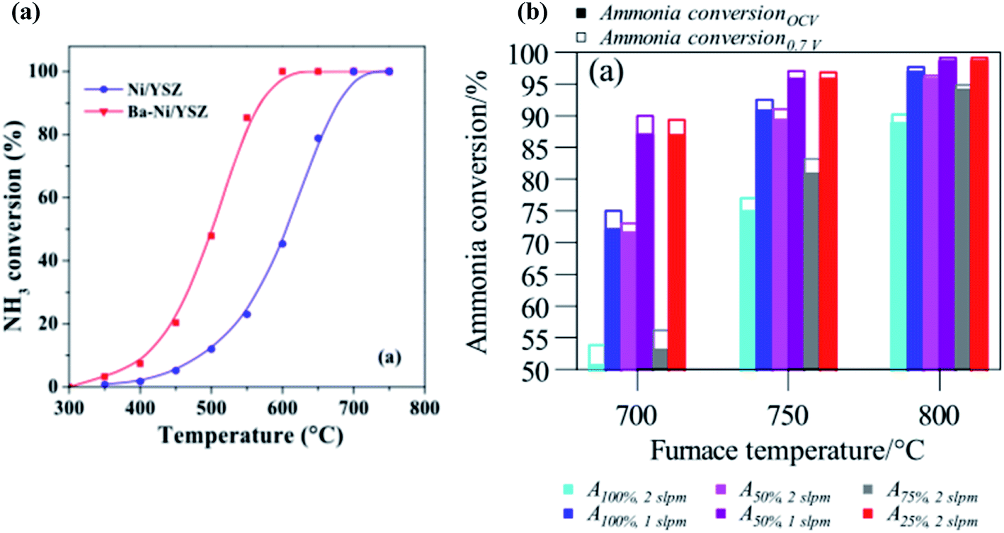 | ||
| Fig. 3 (a) Ammonia conversion of Ni/YSZ and Ba–Ni/YSZ catalysts at 300–750 °C.87 From IOP Publishing, Copyright 2020. (b) Comparison of the ammonia conversions of solutions containing various ammonia dilutions over a Ni–YSZ anode.102 From Elsevier, Copyright 2019. | ||
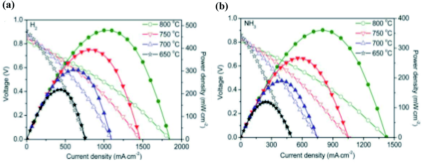
As ammonia is suggested as an alternative to hydrogen fuelled cells, it is important to compare the two fuels in terms of their power output. A key observation to note is the progressively similar performances between ammonia-fed and hydrogen-fed SOFC-Os as temperature is increased, especially at temperatures elevated above 600 °C.96,104,105 Shy et al. employed a Ni–YSZ anode, YSZ electrolyte and LSC–GdxCe1−xO2−δ LSC–GDC cathode and compared the performances between the cells fuelled with both ammonia and hydrogen.106 When increasing the operating temperature from 750 to 800 °C, peak power densities increased from 950 to 1078 mW cm−2 and 1025 to 1104 mW cm−2 for ammonia and hydrogen, respectively. When temperatures were elevated further to 850 °C, peak power densities increased to 1174 and 1192 mW cm−2 for ammonia and hydrogen, respectively. The progressively similar results between ammonia and hydrogen-fed fuel cells demonstrate the feasibility of ammonia as a suitable substitute for hydrogen as a fuel. This is due to the more extensive decomposition of ammonia at increasing temperatures, thus more closely resembling that of pure hydrogen-fed fuel cells. Furthermore, Song et al. recently conducted a study comparing an ammonia and hydrogen-fed SOFC using a LSTCN on SDC anode, SDC electrolyte and Ba0.5Sr0.5Co0.8Fe0.2O3−δ (BSCF) cathode.90 The results are shown in Fig. 4. The ammonia-fed SOFC demonstrates lower peak power densities compared to the hydrogen-fed counterpart, partially due to the lower hydrogen concentration in ammonia fuel cells compared to pure hydrogen fuel caused by the diluting effect of nitrogen as the other ammonia decomposition product.
 | ||
| Fig. 4 Fuel cell performances of SOFCs with an LSTNC on SDC anode fuelled with (a) hydrogen and (b) ammonia at 650–800 °C.90 From Wiley, Copyright 2020. | ||
Table 2 lists some SOFC-O compositions which have demonstrated good performance. Typically, different electrolyte thicknesses and operating temperatures have been employed, making it difficult to draw direct comparisons between systems.
| Anode reaction: H2 → 2H+ + 2e− | (7) |
| Cathode reaction: O2 + 2H+ + 2e− → H2O | (8) |
 | ||
| Fig. 5 Schematic illustration of ammonia-fed SOFC-H. | ||
These ammonia fuel cells based on proton-conducting electrolytes are encouraging candidates for SOFC technology since they maintain good ionic conductivity at lower temperatures compared to SOFC-Os. As efficient proton conductivity can therefore be achieved at lower temperatures, the choice of materials that can be used is expanded since catalyst sintering and thermal expansion mismatch of SOFC components are minimised.109,110 Water/steam is formed at the cathode side, and will not dilute the ammonia fuel at the anode. Lower operating temperatures in systems employing oxygen ion-conducting ceramic electrolytes would result in lower ionic conductivity, which subsequently would result in high ohmic losses.109
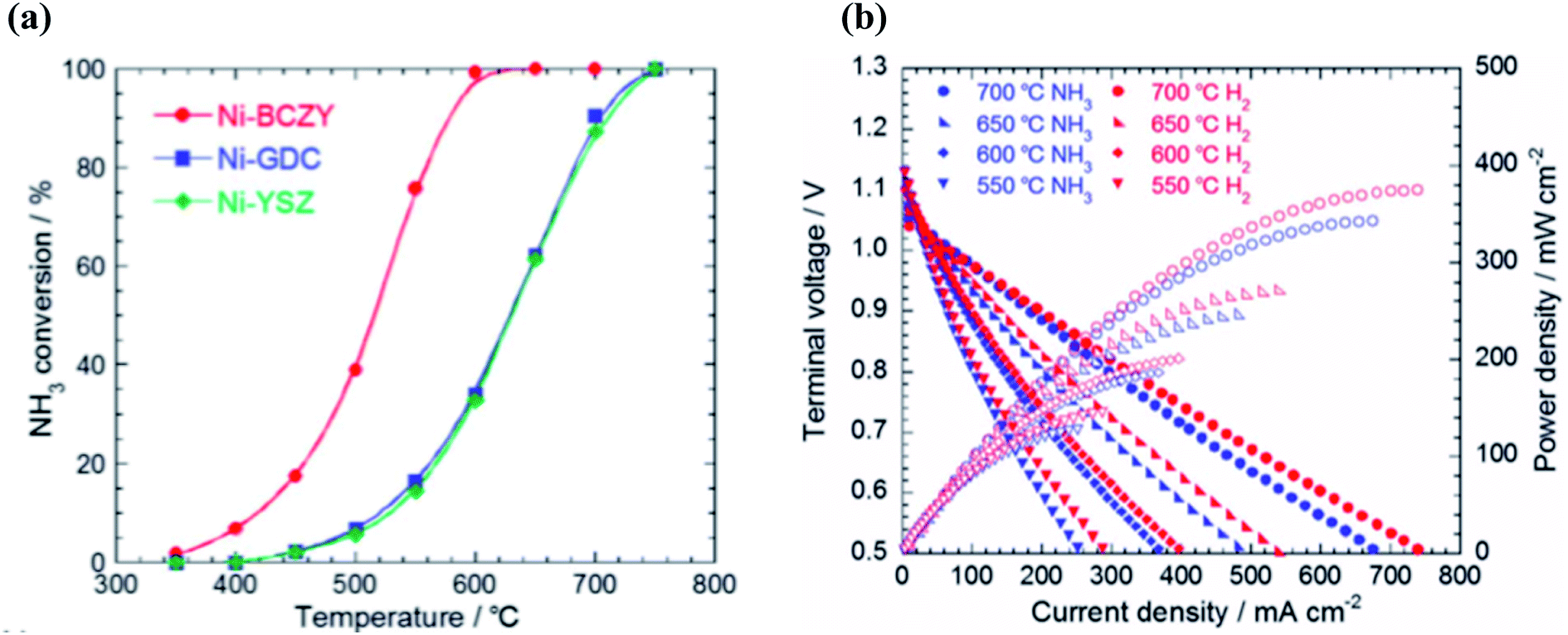
The ammonia decomposition reaction is often impeded by hydrogen adsorption on the catalytic reaction sites. Therefore, a high tolerance to hydrogen poisoning is a crucial factor for catalysts with high activity towards ammonia decomposition. Ni–BaCe0.4Zr0.4Y0.2O3−δ (Ni–BCZY), for example, has a higher tolerance to hydrogen poisoning than Ni–YSZ and Ni–GDC and thus displays greater catalytic activity towards ammonia decomposition. Miyazaki et al. investigated the effect of ammonia decomposition over a range of anodic materials in ammonia fuelled SOFC-Hs.119 It was found that the performance was significantly dependent on ammonia decomposition at the anode and that anodic temperature, due to the endothermic nature of ammonia decomposition, had a direct effect on the extent of conversion. For Ni–YSZ and Ni–GDC anodes, temperatures of 750 °C were required for complete decomposition of ammonia. In contrast, Ni–BCZY completely decomposed ammonia at 600 °C.
Ammonia conversion efficiency against the effect of temperature was recently evaluated by Miyazaki et al., who used a Ni–BCZY catalyst as the anodic component.119 It was found that the conversion of ammonia increased from less than 10% at 400 °C to 40 and 100% at 500 and 600 °C, respectively. This demonstrates a significant increase in ammonia decomposition with rising temperature, especially as temperatures tend towards and rise above 600 °C.
Similar to SOFC-Os, the performances of ammonia-fed and hydrogen-fed SOFC-Hs have also been compared.104,110,120 Miyazaki et al. reported a SOFC-H set up employing ammonia and hydrogen gas as the anodic fuel.119 The set up involved a Ni–BCZY anode, BCZY electrolyte and LSCF cathode, operating at a temperature range from 550–700 °C. At a lower temperature of 550 °C, peak power densities of 130 and 140 mW cm−2 were obtained for ammonia and hydrogen as a fuel, respectively. As temperatures were further elevated to 700 °C, peak power densities of 320 and around 380 mW cm−2 were obtained for ammonia and hydrogen as a fuel, respectively. Here, the differences in power densities between the ammonia-fed and hydrogen-fed fuels at 700 °C seem larger than those at lower temperatures; this can be related to the difference in local partial pressure of hydrogen at the anodic side. The performances of such are demonstrated in Fig. 6.
 | ||
| Fig. 6 (a) Ammonia conversion percentages over different cermets in the presence of 100% ammonia. (b) Fuel cell performance of a Ni–BCZY|BCY20|BCY20–LSCF at 550–700 °C using 66.7% NH3-33.3% Ar or 60.0% H2-40.0% Ar as the anodic gas and O2 as the cathodic gas.119 From RSC, Copyright 2020. | ||
Temperature dependent effects have also recently been reported by Aoki et al., who employed a fuel cell utilizing a Pd anode, BZCY electrolyte and La0.6Sr0.4Fe0.8Co0.2O3 (LSFC) cathode, with both ammonia and hydrogen as the anodic fuel.121 The peak power density obtained at 450 °C was 71 mW cm−2 when operated with ammonia. As the temperature was increased to 500, 550 and 600 °C, the peak power density was enhanced from 210, 340 and 580 mW cm−2, respectively. The excellent performance of the hydrogen fuel cell could be related to the high catalytic activity of Pd in its ability to dissociate H2 molecules. However in terms of cost, Ni-based anodes are a more viable choice. These results are the highest documented power densities reported in the literature to date and the performance of this cell is displayed in Fig. 7.
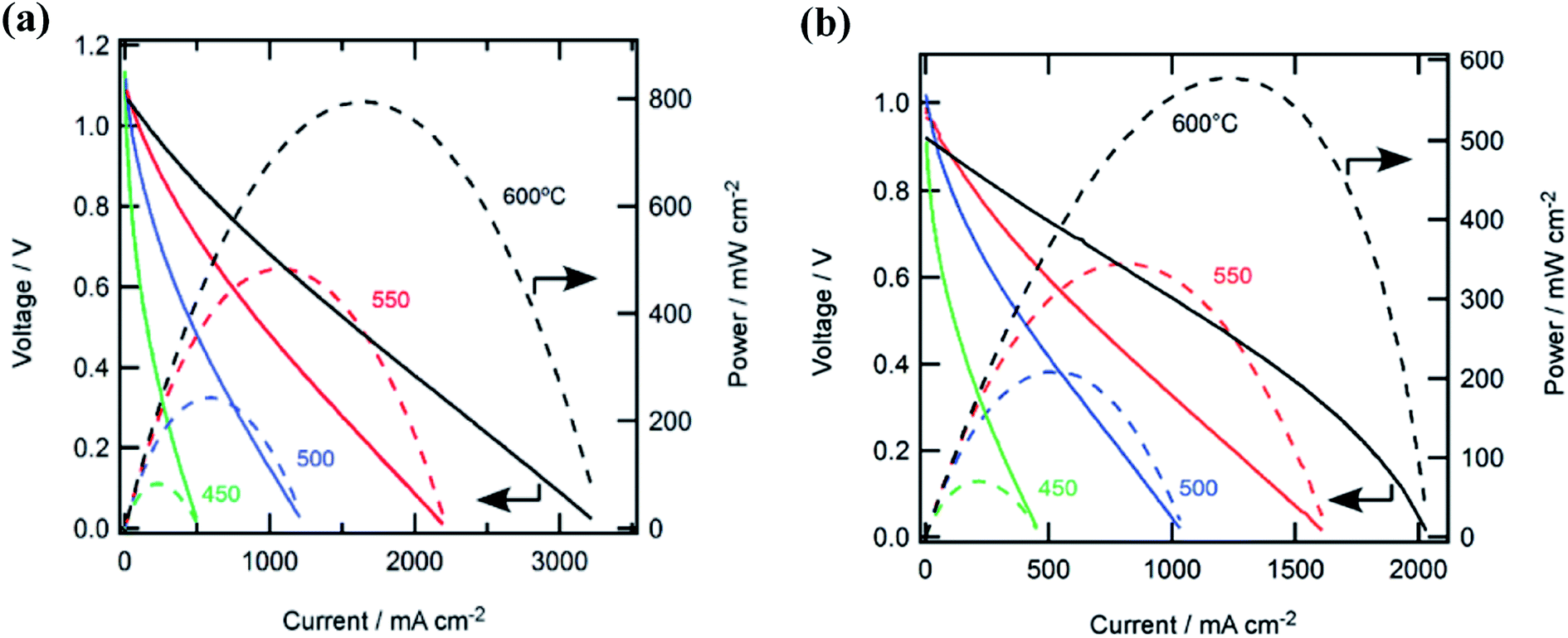 | ||
| Fig. 7 (a) Cell performances with hydrogen fuel at various temperatures. (b) Cell performances with ammonia fuel at various temperatures.121 Open Access 2018. | ||
Table 3 lists some SOFC-H compositions which have demonstrated good performance. Similar to SOFC-O systems, different electrolyte thicknesses and operating temperatures have been employed, making it difficult to draw direct comparisons between systems.
| Anode | Cathode | Electrolyte | Electrolyte thickness [μm] | T [°C] | OCV [V] | Peak power density [mW cm−2] | Ref. |
|---|---|---|---|---|---|---|---|
| Ni–BaCe0.8Gd0.2O2.9 (Ni–BCGO) | La0.5Sr0.5CoO3−δ (LSCO) | BaCe0.8Gd0.2O2.9 (BCGO) | 50 | 600 | 1.102 | 96 | 97 |
| 650 | 1.095 | 184 | |||||
| 700 | 0.995 | 355 | |||||
| 750 | 0.985 | 384 | |||||
| NiO–BaCe0.85Eu0.15O3 (BCE) | Pt | BaCe0.8Gd0.15Pr0.05O3 (BCGP) | 1000 | 500 | 0.92 | 15 | 122 |
| 550 | 18 | ||||||
| 600 | 28 | ||||||
| Ni–Ce0.8Gd0.2O3−δ (Ni–CGO) | Ba0.5Sr0.5Co0.8Fe0.2O3−δ (BSCFO)–CGO | BaCe0.8Gd0.2O3−δ (BCGO) | 30 | 600 | 1.12 | 147 | 110 |
| 650 | 1.10 | 200 | |||||
| NiO–BaCe0.9Nd0.1O3−δ (NiO–BCNO) | La0.5Sr0.5CoO3−δ (LSCO) | BaCe0.9Nd0.1O3−δ (BCNO) | 20 | 700 | 0.95 | 315 | 123 |
| Ni–BaZr0.1Ce0.7Y0.2O3−δ (Ni–BZCY) | BaSr0.5Co0.8Fe0.2O3−δ (BSCF) | BaZr0.1Ce0.7Y0.2O3−δ (BZCY) | 35 | 450 | 0.98 | ∼25 | 120 |
| 500 | ∼65 | ||||||
| 550 | ∼125 | ||||||
| 600 | ∼190 | ||||||
| 650 | ∼275 | ||||||
| 700 | ∼325 | ||||||
| 750 | 390 | ||||||
| Ni–BaCe0.75Y0.25O3−δ (Ni–BCY) | Sm0.5Sr0.5CoO3−δ (SSC) | BaCe0.90Y0.10O3−δ (BCY) | 1000 | 550 | ∼1.10 | ∼120 | 124 |
| 600 | ∼1.08 | ∼165 | |||||
| 650 | ∼1.025 | ∼190 | |||||
| Ni–BaZr1−xYxO3−δ (Ni–BZY) | Pt | BaZr1−xYxO3−δ (BZY) | 60–90 | 600 | ∼0.92 | ∼70 | 125 |
| 650 | ∼0.87 | ∼96 | |||||
| 700 | ∼0.80 | ∼130 | |||||
| Pd | La0.6Sr0.4Fe0.8Co0.2O3 (LSFC) | BaZr0.1Ce0.7Y0.2O3−δ (BZCY) | 1 | 450 | 0.98 | 71 | 121 |
| 500 | 1.03 | 210 | |||||
| 550 | 1.00 | 340 | |||||
| 600 | 0.95 | 580 | |||||
| Ni–BCZY | BCY20–LSCF | BCY20 | 50–60 | 550 | ∼1.12 | ∼130 | 119 |
| 600 | ∼1.10 | ∼180 | |||||
| 650 | ∼1.08 | ∼240 | |||||
| 700 | ∼1.06 | ∼340 |
In brief, in ammonia SOFC-O and SOFC-H, from the points of view of NOx formation and the dilution of ammonia fuel, SOFC-H is a better choice.
2.4. Alkaline, molten alkaline and alkaline membrane-based ammonia fuel cells
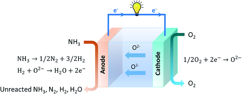
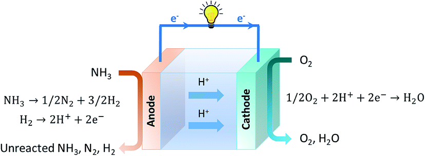
Since the early stages of fuel cell progression, alkaline fuel cells (AFCs) have been studied and employed in practical systems such as space applications, vehicles and energy storage.126–130 The earliest type of ammonia AFC was established in 1960 by Cairns et al., who employed a KOH electrolyte with an operating temperature that varied between 50 and 200 °C.131 These systems produce power by using a KOH electrolyte in a water-based solution, with the OH− ions travelling across the electrolyte to complete the circuit and obtain electrical energy. Following this, much progress has been devoted towards the development of molten hydroxide electrolytes. Hejze et al. reported that when using ammonia as a fuel with a molten hydroxide NaOH/KOH electrolyte at operating temperatures varying from 200–450 °C, a power density of 40 mW cm−2 was obtained at 450 °C.132 Yang et al. similarly investigated an ammonia fuelled molten hydroxide NaOH/KOH fuel cell and obtained a maximum power density of 16 mW cm−2 at 220 °C.133 The NaOH/KOH mixture was also used as a molten electrolyte for a direct ammonia fuel cell which displayed an OCV of 0.4 V and a maximum power density of 0.225 mW cm−2 at 220 °C.134 However, the durability performance of these fuel cells is challenging due to the reaction between CO2 in air and the hydroxide electrolyte, leading to the formation of carbonate ions such as K2CO3 that can precipitate and ultimately poison the cell.Alkaline membrane-based fuel cells (AMFCs) work under similar principles as alkaline fuel cells as they also work by transfer of OH− ions through the electrolyte and operate at a low temperature range of approximately 50–120 °C.129 Oxygen is introduced at the cathodic component where a reaction with water occurs to generate OH− ions. The OH− ions are then transported across an alkaline-based membrane to the anodic side, where they react with ammonia to produce nitrogen and water. For the first low temperature direct ammonia fuel cell based on either an alkaline exchange membrane (AEM) or acidic cation exchange membrane (CEM), a Nafion membrane electrolyte was reported by Tao's group.135,136 When an alkaline membrane is used as the electrolyte, the reactions that occur at the anode and cathode are given below and a schematic overview is provided in Fig. 8.135
| Anode reaction: 2NH3 + 6OH−→ N2 + 6H2O + 6e− | (9) |
 | (10) |
| Overall reaction: 2NH3 + 3/2O2 → N2 + 3H2O | (11) |
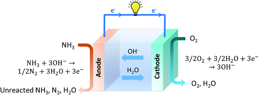 | ||
| Fig. 8 Schematic illustration of an ammonia-fed AMFC. | ||
This is considered a clean technology since the only products of the cell are water and nitrogen. Unlike SOFCs, where the ammonia is initially decomposed into its constituent elements, AMFCs use ammonia directly as a fuel. This mitigates the need for high temperatures and the reaction proceeds regardless of the decomposition step.137,138
To enhance the power density of the fuel cell, OH− ions are typically introduced into the anodic component to increase the rate of the reaction stated in eqn (9). The rate of ammonia oxidation is less limited by the mass transfer of OH− ions across the electrolyte. Hence many researchers investigate not only the effect of ammonia concentration, but also that of OH− ions.
AMFCs are considered an attractive competitor of proton electrolyte membrane fuel cells (PEMFC), which are traditionally used within hydrogen fuel cells. The latter of the two operates under acidic conditions and subsequently tends to employ expensive Pt-based electrocatalysts that can endure such low pH environments. AMFCs, however, are compatible with a greater selection of materials.42,44 This will be discussed in greater detail in Section 2.4.2.
Alkaline membranes are susceptible to reaction with CO2 in air; however unlike conventional AFCs, precipitates such as K2CO3 and Na2CO3 do not form within these systems. Instead, CO2 reacts with OH− to form CO32− ions.3 The presence of CO32− ions is challenging since these ions have a relatively low specific conductivity, four times lower than that of OH− ions. This reduces the overall conductivity of the electrolyte membrane, increases electrolyte resistance and consequently leads to reduced performance. Along with lowered conductivity, the presence of CO32− ions dilutes the number of available OH− ions available to react with ammonia and lowers local pH values.140 The carbonation reaction of OH− ions is shown below:
| CO2 + 2OH− → CO32− + H2O | (12) |
Good chemical stability of a hydroxide-conducting electrolyte is crucial to achieve practical longevity of AMFCs. More than often, pure O2 or CO2 free air is used as the oxidant at the cathode to avoid the formation of CO32− ions.129,140 From this point of view, it is desired to develop CO2-tolerant OH− ion conductors to be used as electrolytes for AMFCs.
The choice of electrolytes for ammonia-fed AMFCs is based on good chemical stability, high ionic conductivity and robust mechanical properties.141 Since these systems are also concerned with the transportation of OH− ions produced at the cathode and consumed at the anode, the electrolyte must also demonstrate resistance to water swelling. Water uptake is therefore another important parameter in regard to membrane employment.141–144 Reviews on AMFC properties have been widely documented.140,145–147 AMFCs typically operate at a temperature that is determined by the durability of the alkaline membrane.145 Commercially available AEMs such as Tokuyama A201 are offered for use within fuel cells and require specific operating conditions including maximum current density and temperature limits that they can withstand. Beyond these limits, the membranes lose their functionality and are deemed unstable for use.148 Recently, the power density and longevity of membranes to be used within AMFCs have been improved due to the development of AEMs with high conductivity and better chemical and mechanical stability.149 Great efforts have been devoted towards synthesising AEMs with alkaline stability at 80 °C or higher.142,143,145,150 These membranes are typically designed based on two distinctive features: a polymer backbone and an ion conductive moiety.151 Wang et al. reported the synthesis of a poly(aryl piperidinium) (PAP) membrane and showed a steady increase in OH− conductivity across the membrane as temperature was increased.150 The conductivity more than doubled, from 78 to 193 mS cm−1, as the temperature was elevated from 20 to 95 °C. Increased OH− conductivity across the membrane can in turn lead to faster reaction kinetics at the anodic side since OH− ions are delivered at a faster rate. Likewise, Lee et al. demonstrated a similar trend when using a PAP membrane.142 It was found that OH− conductivity increased from 54 to 112 mS cm−1 as temperature was elevated from 25 to 80 °C. It should also be noted that at this elevated temperature, a greater water uptake was also observed. The use of such polymer-based membranes is an encouraging direction for use within AMFCs in order to overcome the temperature dependent limitations associated with conventional AEMs.
Similar to SOFCs, the electrolyte thickness of AMFCs is a crucial factor of fuel cell performance. Membrane related ohmic losses within the AMFC can be reduced by the use of a thinner membrane. This decreases diffusion and mass transfer distances that the OH− must cross, so the reactant can be delivered to the anode at a faster rate. Whilst pursuing thinner membranes, good mechanical properties and mechanical robustness must not be compromised.140 Reducing the membrane thickness too greatly could lead to fuel permeation across the membrane, resulting in fuel crossover and potential flooding of the cathode side.41 This has been observed in cases which have led to a reduced OCV and overall fuel cell performance.152
Materials that show promising activity towards the AOR can be categorized into three groups: (i) Pt-based materials, (ii) Ni-based materials and (iii) other Pt-free catalysts. Pt and Pt-based materials are the most widely employed and well-established catalysts towards the AOR, and for this reason they are extensively documented.41,155–158 However, due to expense, scarcity and instability, the use of Pt is limited and the need to develop Pt-free catalysts is essential for a cost effective route towards the AOR. Ni and Ni-based materials are encouraging candidates since they are more readily affordable and exhibit great activity.
From DFT calculations, Ni is predicted to have an encouraging AOR onset potential of 0.33 V vs. RHE. However, the kinetics of N–N association leading to the formation of a hydrazine like species is restricted by a high energy barrier of 1.39 eV due to strong N bonding.153 Despite pure Ni demonstrating poor activity, potential cycling in alkaline media can activate the species and form a protective Ni(OH)2 layer, which can then be converted into NiOOH through a redox reaction.159 It has been reported that in many cases, the latter species is responsible for ammonia oxidation and its activity for such is well documented.160,161 A direct electron transfer mechanism from ammonia to NiOOH has been suggested, as shown in eqn (13). It is also possible, however, that the AOR proceeds via an indirect electron transfer mechanism, whereby ammonia is oxidised and NiOOH is reduced to Ni(OH)2.162
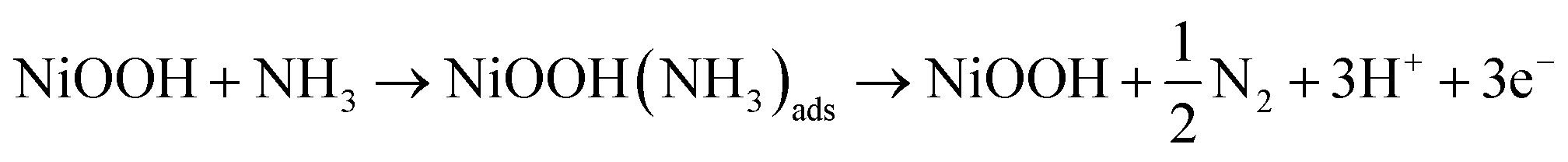 | (13) |
Ni-based AOR catalysts are often challenged by corrosion of the catalyst which can lower the overall efficiency. Moreover, the potential at which the AOR occurs on the Ni/Ni(OH)2 electrode tends to overlap with the Ni(II)/Ni(III) redox potential. To overcome these barriers, several pathways have been suggested such as the use of Ni alloys and manipulation of surface sensitive synthesis to optimise the Ni nanoparticle structure.41,162,163 By introducing a metal that has a high activity towards the AOR but a low affinity for N, with a metal that has a low activity but a high affinity for N, a synergistic effect is present.155,157,158,164 Many experimental findings have demonstrated both improved AOR activity and material stability of Ni-based catalysts on introduction of another metallic species to form an alloy. Such active materials for the AOR can be used as anodic components for AMFCs. For example, Ni2P supported on nickel foam has been reported as an excellent catalyst for electrochemical oxidation of ammonia.165
Non-precious metals have been alloyed with Ni to produce bimetallic species with increased activity towards the AOR, with lowered onset potentials and enhanced current densities.163,166–168 Cu is an exceptional doping element due to the synergetic effect between Ni and Cu which display different N-bonding strengths. It has been found to enhance the AOR current density and endure resistance towards electro-dissolution due to enhancement of surface active sites.163,166 Xu and Tao et al. reported the use of hierarchical NiCu layered hydroxide (LH) nanowires which were directly grown on carbon cloth using hydrothermal synthesis.163 An optimized elemental ratio of Ni0.8Cu0.2 was chosen and the activity against pure Ni(OH)2 electrodes was investigated. The Ni0.8Cu0.2 LH demonstrated a substantial increase in current density reaching 35 mA cm−2 at 0.55 V in 0.5 M NaOH and 55 mM NH4Cl. This activity was greater than those of pure Ni(OH)2 and commercial Pt/C which were found to be 5 and 9 mA cm−2, respectively. Despite the ambiguity over the precise mechanism, it was suggested that the introduction of Cu may have assisted the generation of an additional metal hydroxide, CuOOH, double hydroxides, Ni1−xCux(OH)2, and oxyhydroxides, NixCu1−xOOH. The performance is illustrated in Fig. 9.
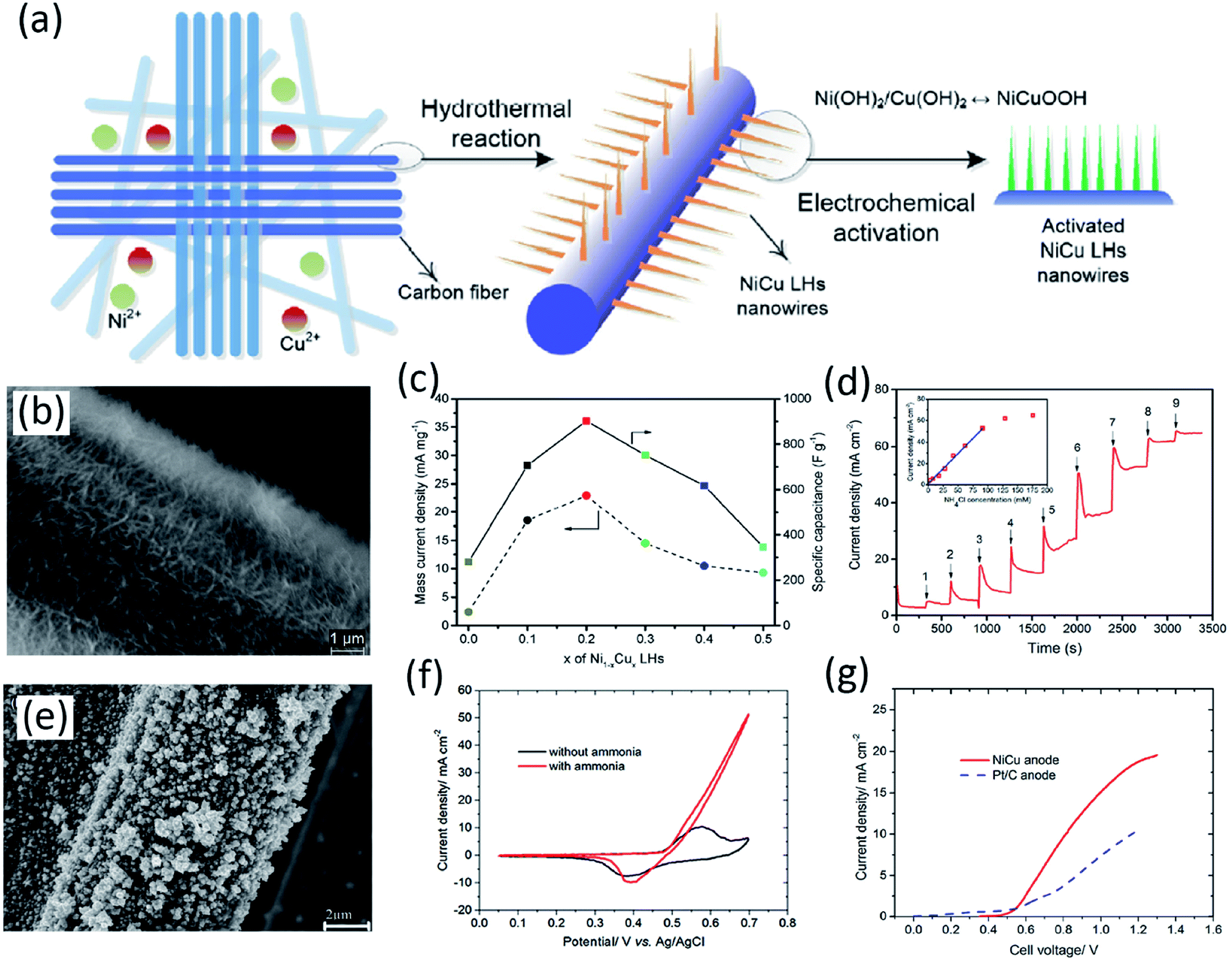 | ||
| Fig. 9 (a) Catalyst preparation of NiCu LH nanowires and electrochemical activation of the electrode. (b) SEM images of Ni0.8Cu0.2 LHs growing on a CFC electrode. (c) Relationship between x in Ni1−xCux LHs and mass current density as well as specific capacitance. (d) Current response of Ni0.8Cu0.2 LHs against sequential injections of an NH4Cl solution to 1 M NaOH at room temperature; anode potential 0.55 V vs. Ag/AgCl.163 Open Access 2017. (e) SEM images of a NiCu/CP electrode after ammonia electrolysis tests. (f) CV of the NiCu/CP electrode in 0.5 M NaOH with and without 55 mM NH4Cl at 25 mV s−1 and room temperature. (g) Comparison between LSV data of a NiCu and Pt/C anode in 0.5 M NaOH + 55 mM NH4Cl with a sweep rate of 1 mV s−1.166 Open Access 2018. | ||
Jiang et al. carried out a series of CV tests to compare the effect of Cu doping in Ni-based electrocatalysts.169 It was revealed that ammonia oxidation catalyzed by NiOOH alone endured a high onset potential of 1.52 V vs. RHE, whilst the introduction of Cu lowered the onset potential to 1.40 V. Zhang et al. investigated the extent of Cu doping on fuel cell performance with a system that utilised 0.5 M NH3 and 1 M KOH as the fuel and a Pt cathode at an operating temperature of 25 °C.170 It was found that when increasing the Cu percentage from 0, 30 and 50%, the NiCu catalyst showed an increasing peak power density of 1.84, 2.91 and 5.06 mW cm−2, respectively. On further increasing to 70 and 100%, the peak power density began to fall to 4.67 and 1.18%, respectively, emphasising the profound effect of the elemental ratio and composition on the performance of the cell. The NiCu/C catalyst has therefore been demonstrated as a good anode for conventional ammonia fuel cells.171–173
Besides metal alloys and their derivatives of metal hydroxides and oxyhydroxides, perovskite oxides such as SrxLa1−xMnyCo1−yO3−δ also exhibit good catalytic activity towards electrochemical oxidation of ammonia. For example, Sr0.3La0.7Mn0.4Co0.6O3−δ on a Ti plate exhibits the highest activity.174 Similarly, another perovskite oxide, SrFe0.3Ni0.7O2.85, also exhibited good activity.175 The high activity can be related to the multi-valent transition elements at the B-sites.
For the electrocatalyst choice for cathodes in ammonia-fed AMFCs, catalysts displaying good activity towards the ORR under alkaline conditions, according to reaction (10), can be used. There are many studies reporting ORR catalysts under alkaline conditons, including metals, alloys, oxides, etc.176,177 In 2019, Tao's group reported the novel use of the perovskite oxide SrCo0.8Cu0.1Nb0.1O3−δ as a cathode for AMFCs in a two electrode cell, demonstrating perovskite oxides as promising cathodes for AMFCs in real applications.171 Research on perovskite oxides as a cathode for ammonia-fed AMFCs was further extended to a similar oxide, SrFe0.8Cu0.1Nb0.1O3−δ.178 In a recent study, we found α-MnO2 to be an excellent non-noble cathode for direct ammonia AMFCs.173 In comparison to the anode, the search for cathode materials for use within AMFCs is not as strenuous as many ORR catalysts under alkaline conditions have already been established in the public domain. Good electrocatalysts for the AOR at the anode are therefore key in direct ammonia-fed AMFCs and are the focus of this review.
Table 4 lists some AOR Ni-based catalysts which have demonstrated good performance. Typically, various electrolyte compositions and reference electrodes are employed, resulting in difficulty in drawing direct comparisons between studies. The establishment of a baseline is therefore necessary for clear and direct AOR exploration. At present, Pt- and Ni-based materials are key candidates for catalysts towards the AOR.
| Catalyst | Fuel | Scan rate [mV s−1] | T [°C] | E p [V] | Current density [mA cm−2] | Ref. |
|---|---|---|---|---|---|---|
| Ni(OH)2 | 0.5 M NaOH + 55 mM NH4Cl | 25 | 25 | 0.55 V vs. Ag/AgCl | 5 | 163 |
| NiCu | 0.55 V vs. Ag/AgCl | 35 | ||||
| NiMn | 0.50 V vs. Ag/AgCl | 20 | ||||
| NiFe | 0.50 V vs. Ag/AgCl | 25 | ||||
| Ni93Pd7 | 0.5 M NaNO3 + 200 mM NH4NO3 | 50 | 25 | 1.25 V vs. HgO/Hg | 60 (A g−1) | 168 |
| Ni98Pd2 | 150 (A g−1) | |||||
| NiCu | 0.5 M NaOH + 55 mM NH4Cl | 50 | 25 | 0.70 V vs. Ag/AgCl | 52 | 166 |
| NiCu | 1 M KOH + 0.5 M NH3 | 50 | 25 | 0.65 V vs. HgO/Hg | 110.4 | 179 |
| PtNi | 1 M KOH + 0.1 M NH3 | 10 | 25 | 0.69 V vs. RHE | 75.32 (A g−1) | 180 |
| Ni | 0.33 mM NH4+ + 0.5 M KOH | 120 | 25 | 0.45 V vs. HgO/Hg | ∼9 | 181 |
| Co10/Ni | 0.38 V vs. HgO/Hg | ∼8.5 | ||||
| NiO | 200 mM NH4OH + 100 mM NaNO3 (+3 M NaOH) | 100 | 25 | 1.28 V vs. HgO/Hg | 2.93 | 182 |
| NiO–TiO2 | 3.01 | |||||
| Pt | 1 M KOH + 0.1 M NH3 | 50 | 25 | −0.25 V vs. Ag/AgCl | 1.63 | 183 |
| PtNi | 2.39 | |||||
| PtNiO | 2.72 | |||||
| PtIr | 1 M KOH + 0.1 M NH3 | 5 | 25 | ∼0.65 V vs. RHE | 25.1 (A g−1) | 184 |
| PtIr/SiO2–CNT–COOH | ∼0.70 V vs. RHE | 90.6 (A g−1) | ||||
| PtIrNi/SiO2–CNT–COOH | 124.0 (A g−1) | |||||
| Pt | 1 M KOH + 0.5 M NH3 | 20 | 25 | −0.2 V vs. Hg/HgO | ∼0.34 | 185 |
| Pt 100 | ∼0.95 | |||||
| PtSnO2 | ∼0.50 | |||||
| PtSnO2 100 | ∼0.75 | |||||
| Pt | 0.05 M KOH + 100 mM NH3 | 50 | 25 | 0.7 V vs. RHE | ∼0.42 | 186 |
| Pt plate | 1 M KOH + 1 M NH3 | 10 | 25 | −0.23 V vs. Hg/HgO | 1.7 | 187 |
| Pt-black | 20 | |||||
| Pt–CNT (160 °C) | ∼−0.19 vs. Hg/HgO | ∼58 | ||||
| Pt NC | 0.1 M KOH + 0.1 M NH3 | 50 | 25 | ∼0.78 V vs. RHE | 0.58 | 188 |
| Ir and Ni(OH)2-decorated Pt NC | 0.82 V vs. RHE | 0.72 | ||||
| Ir-Decorated Pt NC | 0.75 V vs. RHE | 1.25 |
Zhao et al. reported a fuel cell based on a synthesised alkaline PAP membrane, a PtIr anode and an Acta 4020 cathode.189 When using 3 M NH3 and 3 M KOH as the anodic fuel and O2 as the oxidant at the cathode, a maximum power density of 135 mW cm−2 was reported at an operating temperature of 80 °C. It is important to note that KOH is often required at the anodic side and that pure O2 is often used at the cathode due to the sensitivity of the polymeric alkaline membrane electrolyte to CO2. This makes the use of ‘free’ air as the oxidant at the cathode difficult. These factors highlight the challenges for high performance ammonia-fed AMFCs.
Achrai et al. recently published the results of using an ammonia-fed AMFC with a KOH-free anode feed at operating temperatures of up to 120 °C.190 Two different fuel cell set ups were explored using temperature ranges from 60–95 °C and 100–120 °C, respectively. The results of these cells are shown in Fig. 10. The former employed a PtIr anode, PAP-TP membrane and Fe–N–C cathode and achieved a maximum power density of around 80 mW cm−2 at 95 °C when gaseous ammonia was used as the anodic feed. When Pt1Ir10 was employed as the anode, a Tokuyama membrane and Ag cathode were used in a cell fuelled with 16 M ammonia solution. At a temperature of 120 °C, an impressive peak power density of 180 mW cm−2 was obtained, a record high for this fuel cell type. This study not only illustrates the potential of AMFCs to be studied at temperatures higher than room temperature, as is usually recorded, but also demonstrates the ability to reach high peak power densities in the absence of NaOH/KOH. In doing so, the addition of alkali is avoided, saving costs on materials and workup time. It should be noted that whilst the maximum power density is less than that reached by a similar fuel cell with added KOH, the gap is decreased when using a high concentration (16 M) of ammonia and back pressures on both sides of the fuel cell. However, there are still at least two key obstacles facing this type of ammonia AMFC. The cost of a Pt1Ir10 anode is considerably high and O2 or CO2 free air must be used as the cathode fuel since the membranes are not compatible with CO2. In 2019, the global production for iridium was around 6860 kg, insufficient for large scale commercial fuel cell applications.191 It is therefore desired to use readily available, non-precious metal catalysts in direct ammonia AMFCs. Long term stability could be another challenge for large scale applications. However, this study indicates that direct ammonia AMFCs do have the potential to achieve high power density for real applications, such as in electric vehicles.
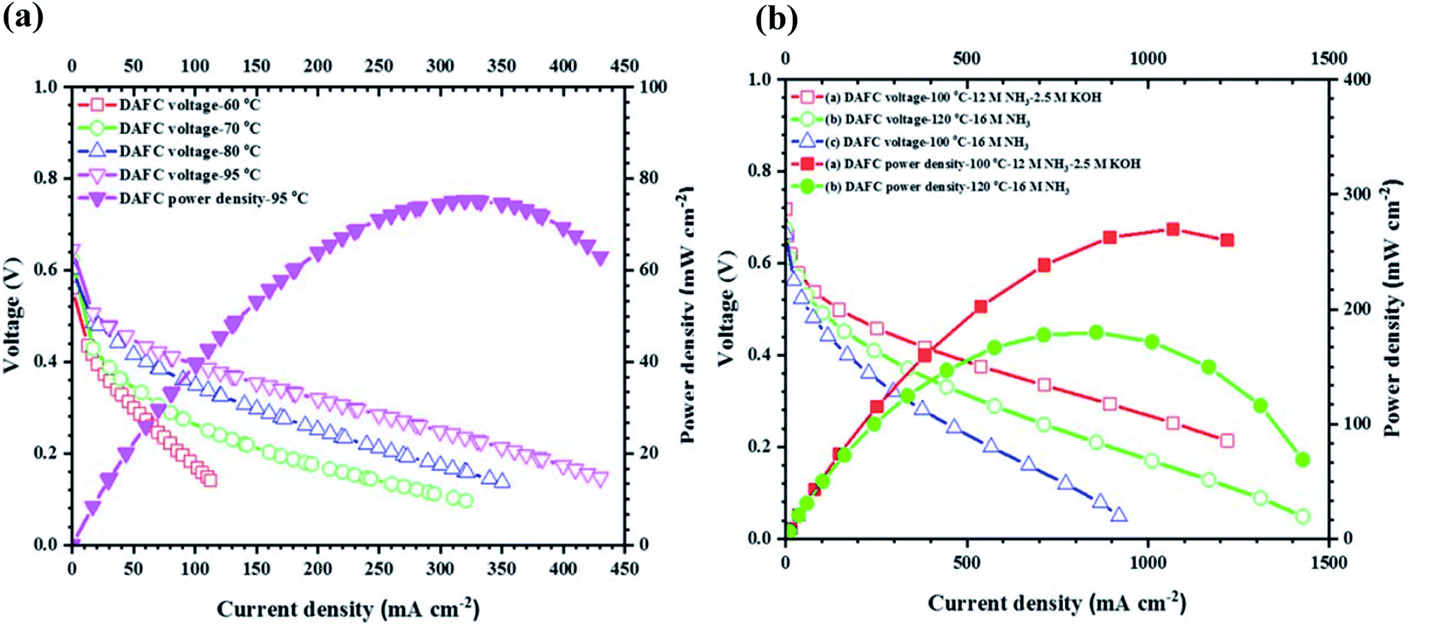 | ||
| Fig. 10 Fuel cell performance of a KOH-free AMFC at temperatures ranging from (a) 60–95 °C and (b) 100–120 °C.190 From IOP Publishing, Copyright 2020. | ||
Table 5 lists some AMFC compositions which have demonstrated good performance. Although not as much data has been reported in terms of varying operating conditions as compared to SOFC systems, comparisons between performances can still be drawn.
| Anode | Cathode | Electrolyte | Fuel | T [°C] | OCV [V] | Peak power density [mW cm−2] | Ref. |
|---|---|---|---|---|---|---|---|
| PtIr | Acta 4020 | PAP-TP (10 μm) | 3 M NH3 + 1 M KOH | 80 | 0.63 | 121 | 189 |
| 3 M NH3 + 3 M KOH | 135 | ||||||
| 3 M NH3 + 5 M KOH | 117 | ||||||
| Pt-Based | Non-Pt-based | Commercial alkaline exchange membrane (AEM) | NH3 + aq. base | 100 | 0.70 | 450 | 192 |
| NiCu | Pt | Use of Laminar Flow | 1 M NH3 + 1 M KOH | 25 | 1.15 | 5.06 | 170 |
| 1 M NH3 + 2 M KOH | 1.30 | 9.21 | |||||
| 1 M NH3 + 3 M KOH | 1.31 | 10.94 | |||||
| Cr-Decorated Ni | MnO2 | Resin-PVA | 35% NH3 | 25 | ∼0.82 | ∼9 | 135 |
| CPPO–PVA | Gaseous NH3 | ∼0.65 | ∼11 | ||||
| Pt/Ru | Pt | Mg–Al–CO32− layered double hydroxide (500 μm) | 5 M NH4OH + 1 M KOH | 20 | ∼0.40 | ∼1.25 | 193 |
| 50 | 0.45 | ∼3.2 | |||||
| 80 | ∼0.55 | ∼4.5 | |||||
| NiCu | SrCo0.8Cu0.1Nb0.1O3−δ | Commercial alkaline exchange membrane (AEM) | 35% NH3 + 1 M KOH | 25 | 0.45 | 0.25 | 171 |
| NiCu | SrFe0.8Cu0.1Nb0.1O3−δ | Commercial alkaline exchange membrane (AEM) | 0.02 M NH3 | 25 | 0.35 | 0.03 | 172 |
| PtIr | Fe–N–C | PAP-TP (18 μm) | Gaseous NH3 + 400 ml min−1 N2 | 95 | 0.56 | 75 | 190 |
| Pt1Ir10 | Ag | Tokuyama membrane | 16 M NH3 | 120 | 0.68 | 180 | |
| 12 M NH3 + 2.5 M KOH | 100 | 0.72 | 280 |
2.5. Microbial ammonia fuel cells
Microbial fuel cells (MFCs) are an alternative technology which have gathered attention for their ability to treat wastewater whilst simultaneously generating electricity. This has become a growing topic of interest due to the expansion of the industry along with the intensification of human activities.194,195 Such wastewater can contain notable amounts of ammonia, which if improperly treated, can lead to both environmental and human health risks.196 Biological treatment is traditionally used for the extraction of nitrogen from wastewater; however, high amounts of ammonia may limit efficient biological treatment. It is therefore vital to determine an effective treatment process.197 MFC technology has been considered for this purpose and literature based on MFCs treating wastewater has increased over the years.198–200MFCs are devices that utilise microorganisms and convert chemical energy from biodegradable material into electrical energy.201 Electricity is generated when bacteria on the anode produce electrons via the oxidation of organic substrates present in wastewater.202 The electrons flow from the anodic side via an external circuit where they combine with protons and oxygen to form water at the cathode.203,204 The electricity is harnessed by inserting a load between the two electrodes.
Yang et al. conducted an experiment using a heterotrophic nitrifying/denitrifying air-cathode microbial fuel cell (HND-ACMFC) to investigate ammonia-contaminated wastewater over long periods of operation. Wastewater was fed into a reactor by spraying through the cathode for a short period of time. The organics within the wastewater were oxidized in the anode to generate electrons and protons at the bottom of the reactor setup, as shown in Fig. 11. The electrons were transferred through the external load to the cathode, while the protons diffused to the cathode. In the air-exposed biocathode (AEB), bio-electrochemical reduction reactions were fulfilled accompanied by some biological reactions (e.g. nitrification–denitrification). The HND-ACMFC consequently achieved stable energy recovery and ammonia removal in an economical way.205
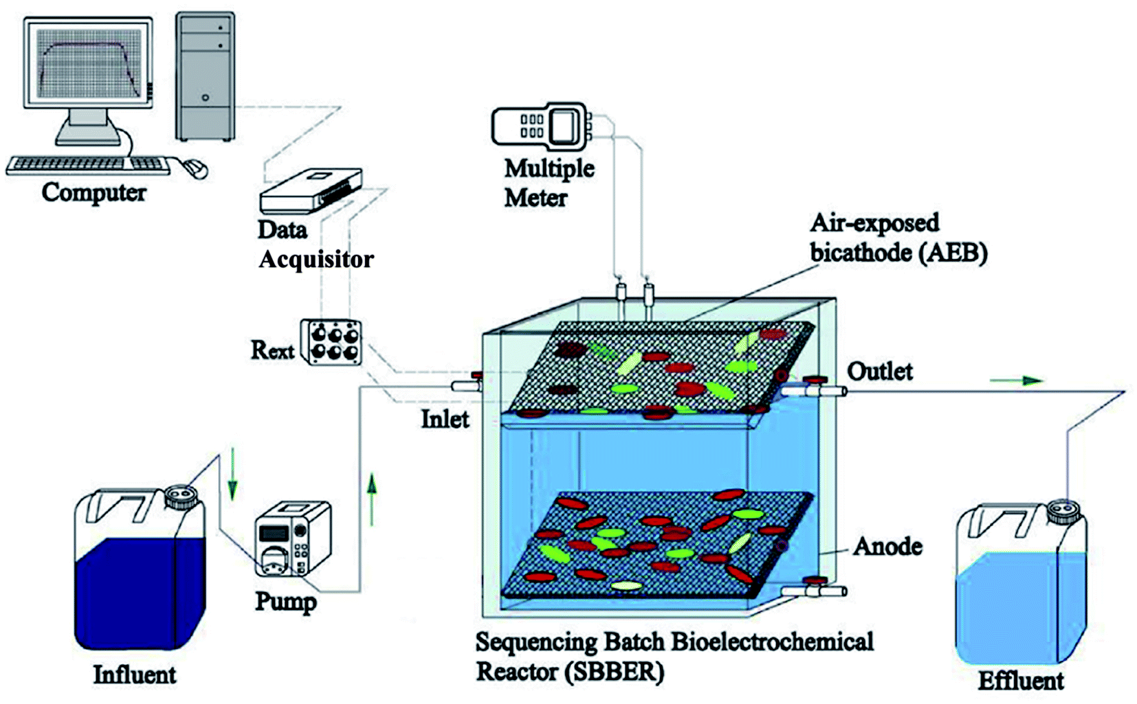 | ||
| Fig. 11 Schematic process of the HND-ACMFC treating ammonia-contaminated wastewater with negative aeration in long-term operation.205 From Elsevier, Copyright 2020. | ||
Yang et al. utilised an air-cathode MFC to simultaneously remove ammonia from wastewater whilst generating power.205 It was reported that a high ammonia removal efficiency of 99% was achieved whilst a maximum power density of 100 mW m−3 was obtained. The use of an air-breathing cathode makes the whole system very simple and easy to scale up, as shown in Fig. 11. Rossi et al. obtained a power output of 132 ± 7 mW m−2 over the duration of one month whilst employing a system that magnetically cleaned the cathodic component.198 The observed system had a power output 42% higher than when no magnet-cleaning controls were used (116 ± 4 mW m−2). The findings highlight the challenges associated with MFCs, that is the reduced performance over time in the absence of efficient cleaning techniques. A limitation in using such technology is the presence of biofouling due to biofilm formation on the cathode and catalyst deterioration. This renders the applicability of MFC technology. Further to this, ammonia emissions of air-cathode MFCs pose a serious environmental and health threat but the control and mitigation of such emissions have not been studied yet. Consequently, Li et al. have recently reported the characterisation and control of ammonia emissions in MFCs.206
MFC technology has also been proposed as a suitable method for air purification by removing ammonia from air. Yan and Liu reported Sn-doped V2O5 nanoparticles as an effective catalyst for the fast removal of ammonia in air via photo-electro-catalysis (PEC) MFCs. An optimal degradation of 96.4% ammonia was achieved and it was shown that the Sn-doping decreased the size of nanoparticles, increased the oxidising capacity and increased the number of active sites. The oxygen vacancies played a particular key role in ammonia oxidation.207
3. Future potential applications
To date, it has been challenging to find a direct comparison between different fuel cell types in terms of their performance since their testing conditions vary greatly. It is necessary to clarify which technology is best suited to specific applications based on their respective conditions and performances. Henceforth, we will discuss the prospects of ammonia-fed-SOFC and AMFC technology based on their performances and testing temperature ranges. Based on current progress, we believe a realistic route for the commercialisation of ammonia-fed fuel cells in the near future is within hybrid technology, transportation and wastewater treatment. Here we discuss the reasoning and potential of ammonia-fed fuel cells within each of these sectors.3.1. Hybrid technology
Before full integration of direct ammonia fuel cells, a more foreseeable pathway in the near future may be a hybrid technology. This would allow society and investors to appreciate and more widely accept ammonia as an energy vector. Hybrid technology would be a realistic initial step towards the integration and incorporation of ammonia within a carbon-free network for the future. A proposal of such a network is illustrated in Fig. 12.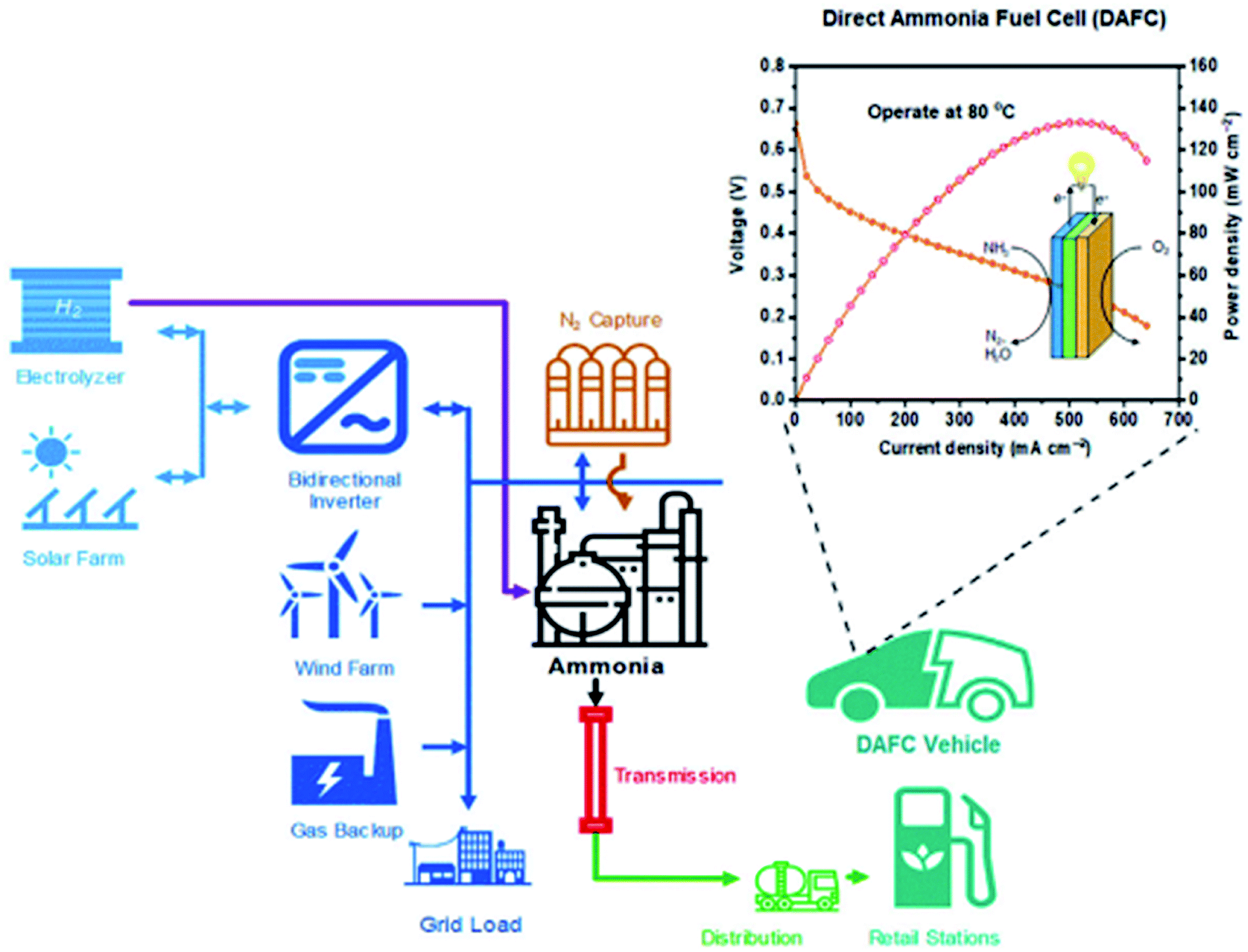 | ||
| Fig. 12 Proposal of combinational systems for future carbon-neutral transportation networks. Reproduced with permission.189 From Elsevier, Copyright 2019. | ||
It has been reported that traditional SOFCs in pressurised atmospheres have been shown to be extremely effective when integrated with gas turbines (GT), achieving efficiencies of up to 70%, the highest efficiency hybrid power generation system known to date.208 Understanding the performance and stability of ammonia-fed SOFCs operating at elevated pressure is important to realise the potential of these systems to replace conventional SOFCs in hybrid SOFC-GTs.209 The performance of an ammonia fuelled SOFC was tested against a hydrogen fuelled SOFC under various atmospheric pressures and temperatures.106 It was found that for both fuel cell systems, power densities increased with pressurisation. When atmospheres were increased from 1 to 3 atm, peak power densities increased from 1078 to 1148 mW cm−2 for the ammonia fuelled cell operating at 800 °C. Under the same conditions, the hydrogen fuelled cell demonstrated an increase of 1104 to 1193 mW cm−2. The results illustrate the potential of ammonia fuelled SOFCs in the development of hybrid pressurised SOFC-gas turbine (SOFC-GT) power generation systems.106,210
Further to this, Ishak et al. explored the integration of ammonia-fed SOFC-GTs in combined cooling, heating and power (CCHP) cycles.211 The refrigeration properties of ammonia were exploited to provide adequate cooling to the trigeneration system with little complexity and cost. At pressures of nearly 5 atm and an operating temperature of 800 °C, the energy efficiency of the SOFC-H integrated cycle reached 81.1% (76.7% when its SOFC-O counterpart is used). Both SOFC-O and SOFC-H demonstrated excellent energy efficiencies of SOFC-GTs at elevated pressure. Hybrids of SOFCs using cogeneration or tri-generation allow recovery of exhaust heat from the cells, improving efficiencies of such integrated systems.212 Additional ammonia SOFC hybrid systems have been explored for power generation in a number of technologies including solar towers and transportation.213–216
Although the use of pure ammonia AMFCs is still in the developmental stages, hybrid technology can be employed to appreciate the concept of ammonia fuel cells in the near future. A recent study conducted by Siddiqui and Dincer presents an integrated solar-based ammonia synthesis and a fuel cell system.217,218 The excess power produced by a solar-based system was used to synthesise ammonia and a direct ammonia fuel cell was used for electricity production at periods of low solar energy. The rate of ammonia synthesis reached a peak of 64.8 mol s−1 and the overall energy efficiency of the integrated system throughout the year ranged between 15.68 and 15.83%. The system demonstrates ammonia as a promising energy storage medium especially for applications of intermittent energy sources.217 Further to this, a novel hybrid ammonia fuel cell and molten salt thermal energy storage system were developed by Siddiqui and Dincer. A maximum power density of 2.1 ± 0.1 W m−2 was obtained demonstrating an AMFC hybrid system.219
Ammonia hydrogen blends may also be a useful starting point, alleviating some of the pressure and reliance on developing pure hydrogen fuel powered technology. Siddiqui et al. investigated AMFC performances with pure ammonia, ammonia hydrogen blends and pure hydrogen whilst using Pt-based electrodes and a commercially purchased anion exchange membrane electrolyte.220 Employing hydrogen–ammonia blends improves fuel cell performances compared to those of pure ammonia. In order to obtain fuel performances that are increasingly similar to those of hydrogen fuel, the nature of ammonia molecules must be further explored. Development of suitable catalysts that can overcome the stable nature of ammonia and combat the lower reactivity compared to hydrogen must be addressed. It may be of interest to explore different fuel blends and configurations to develop hybrid ammonia–hydrogen fuel cells.
The use of renewable fuels, such as biofuels, to complement batteries in a hybrid system would assist in overcoming the range and recharge limitations of batteries. However, the scale of biofuels is restricted by their environmental footprint once land and water usage are taken into consideration.221 Carbon-neutral fuels, such as ammonia, may therefore be a sustainable complement to batteries.189,222,223 Siddiqui and Dincer developed a novel hybrid ammonia fuel cell and battery system through experimental and modelling techniques.222 The system demonstrated enhanced use of electrochemical energy and allowed for the individual components to be utilised sequentially, for example, employment of the AMFC component in periods of battery recharge. Compared to an energy efficiency of 15.2 ± 1.3% for the ammonia-fed AMFC, the ammonia-fed AMFC and battery hybrid system was found to operate at 27.5%. Such hybrid systems provide a promising direction for ammonia fuel cells in the nearby future, where the sole use of ammonia-fed AMFCs may not be at a stage where they are commercially viable.
3.2. Transportation
Ammonia fuelled SOFCs for transportation have more recently been investigated.224 Al-Hamed and Dincer proposed an ammonia-fed SOFC integrated with a gas turbine and ammonia-organic Rankine cycle to recover and utilise waste heat as a tri-generation system for cleaner railway applications.225 The hybrid system was studied using a thermodynamic model to evaluate its energy and power outputs. It was found that the energy efficiency of the integrated system was 58.7%, with no CO2 emissions and sufficient energy demand to satisfy a passenger locomotive. Within this integrated system, 94.5% of the total power output was generated by the SOFC-GT and this predominantly governed the performance of the system. Later, a study using a similar integrated system showed an energy efficiency of 68.5% for a passenger locomotive; this was optimised to 79.88% with an energy efficiency of nearly 79.88% based on the ammonia-fed SOFC component alone.226Along with public transport, power generation from ammonia fuelled SOFCs has been proposed to power fuel cell vehicles (FCV). Perna et al. studied a combined heat, hydrogen and power (CHHP) system, where an ammonia fuelled SOFC was used to produce 100 kg per day of hydrogen to refuel between 20 and 30 FCVs.215 The experiment aimed to meet the demands of hydrogen small scale refilling stations, as well as to produce electricity for electric vehicles and heat for local use. Tests were conducted using a single ammonia fuelled SOFC and different simulation mixtures. The CHHP system showed high efficiencies ranging from 71–81%. Such systems have potential in real life applications as they allow for renewable refuelling stations in regions that are scarce in renewable energy sources such as Korea and Japan. In these regions, it is increasingly attractive to therefore use ammonia as a hydrogen carrier rather than import pure hydrogen. It should be noted that the oxide materials for making SOFCs are fragile, making them challenging to directly power electric vehicles. SOFCs based on metal current collectors are more robust. Further research is required to determine whether these materials are strong enough to be used in transportation applications.
AMFCs may be a promising technology to power electric vehicles. As of now, power densities of reported direct ammonia AMFCs are not high enough but these AMFCs have shown potential comparable power densities to those of the hydrogen PEMFCs.190 A hybrid type of technology may be used to power electric vehicles whereby ammonia SOFCs can work alongside a battery component to be used as a range extender of an electric vehicle. The electricity from a direct ammonia SOFC may be used to charge the battery during the duration of recharge and electricity from the battery may be used to power the electric vehicle. Further to this, ammonia SOFCs can be used as auxiliary power units (APUs) to supply electricity for lorries, buses, trains and ships.
3.3. Wastewater treatment
Traditional treatment of wastewater can be cost and energy demanding. Microbial fuel cells have been studied as methods to convert sewage directly into electricity, utilizing waste as an energy source.198,227SOFC technology may be considered within wastewater recovery systems. Wastewater contains unused energy in the form of dissolved ammonia. This ammonia source, once extracted from wastewater through pre-treatment, can be used as a promising fuel for SOFCs172,228–230 An example of utilising the ammonia within wastewater is via decomposition of struvite. Struvite precipitation is a method used to remove nutrients such as phosphorus and nitrogen in wastewater. It can be decomposed to ammonia-water mixtures which can then be used to fuel SOFC systems.231
Grasham et al. demonstrated extraction of ammonia from waste to then be utilised within a SOFC.232 It was found that 82% of ammonia was recovered from diverted digestible liquor for use as fuel in a SOFC system to be implemented within wastewater treatment plants. The SOFC ran at an electrical efficiency of 48%, with the extracted ammonia contributing 4.6% of its power output. Using such a method could also reduce carbon dioxide emissions since conventional biological treatment of wastewater often results in greenhouse gas emissions. The use of ammonia from wastewater as a fuel for SOFCs can lead to an estimated reduction of 3.5 kg CO2 per year per person at the treatment facility due to the avoidance of biological processing in conventional wastewater treatment. Further implementation of this type of technology could transform a treatment facility from a net consumer to a net producer of electricity.
Microbial ammonia fuel cells and ammonia-fed AMFCs may also be considered within such technology to make use of the high ammonia content in wastewater.167,171,197,227,233 The key advantage of using such fuel cells within this technology is that they do not require ammonia extraction from wastewater. These systems can be fueled directly with wastewater, eliminating costs and excess energy inputs. Electrooxidation of ammonia has been shown to be a promising method that is also an economical route for ammonia extraction from wastewater.167,234,235 Almomani et al. demonstrated the use of an NiO–TiO2 electrode to remove more than 96.4% of ammonia from real wastewater samples using the electro-oxidation process, validating the suitability of this technology for wastewater treatment.182 Mengfei et al. recently investigated an AMFC directly fed with landfill leachate. The cell set up involved a NiCu/C anode, α-MnO2/C cathode and an alkaline membrane. It was found that the ammonia concentration within the contaminated wastewater was reduced from 2711 to 95 ppm and a removal efficiency of 96.5% was found after the duration of 6 hours. The results also demonstrated a peak power density of 0.081 mW cm−2 at room temperature when the landfill leachate was used to fuel the cell.173
3.4. Life cycle analysis
To fully appreciate the notion of ammonia-fed SOFCs as the next generation of fuel cells, it is imperative to assess the environmental impact of ammonia throughout its lifetime as a fuel. Bicer and Khalid conducted a study to assess the environmental impact in regard to climate change, fossil depletion and human toxicity from power production through SOFCs fuelled by various chemical feedstocks including natural gas, hydrogen, ammonia and methanol.236 It was found that if ammonia was sourced renewably, from wind electrolysis as was the case of this simulation, ammonia-fed SOFCs become the second best choice in the climate change criterion. Such SOFC systems would significantly reduce environmental impacts, yielding 0.16 kg CO2 per kW h electricity. From a comparative perspective, when natural gas was used to fuel a SOFC, 0.41 kg CO2 per kW h electricity was produced. This shows the excellent potential of ammonia as an environmentally friendly vector and its potential progression towards a more sustainable future.Life cycle analysis for AMFCs is less known. However, as detailed above, with the encouraging direction of green ammonia, environmentally friendly production of ammonia could greatly reduce CO2 emissions during its production. Since the use of ammonia directly in an ammonia-fed AMFC is carbon-dioxide free on the user end, this will improve the overall sustainability of ammonia-fed AMFCs.
4. Perspectives and challenges
4.1. Perspectives and challenges of ammonia-fed SOFCs
At present, the most advanced design of SOFCs is the tubular configuration. A recent numerical study by Ilbas et al. indicated that ammonia-fed tubular SOFCs are comparable to that of hydrogen. This can be attributed to their higher volumetric power density, mechanical stability, high thermal shock resistance and absence of sealing issues.237 However, as detailed in previous chapters, SOFCs greatly rely on high operating temperatures to fully appreciate fuel utilisation.238 Along with this, it is well established that the rate of ammonia conversion is somewhat slow and requires the use of a suitable catalyst. This is particularly important in SOFC-Os, where another factor that must be considered is NOx formation due to the presence of water at the anode.Performance durability and fabrication of materials which can endure such high temperatures for an extensive period of time are challenging.41 The choice of catalyst is therefore extremely important in order to avoid chemical compatibility issues in long-term operation. There have, however, been advances in catalyst selection that allow for lower temperatures to be used and sufficient power performance to still be attained, as summarised in Tables 2 and 3. On lowering temperatures, we believe that CsH2PO4 may be a potential electrolyte for intermediate temperature direct ammonia fuel cells since it has shown to be chemically compatible with ammonia at 250 °C.29 As CsH2PO4 is soluble in water, operation of the fuel cells or electrolysers based on the CsH2PO4 electrolyte at a temperature below 100 °C in the presence of liquid water could be difficult.
Further to this, the nature of the fuel should also be considered. Ammonia is very corrosive, particularly in the presence of contaminants such as water vapour and air.239 Anhydrous ammonia is therefore often adequate. For most SOFCs, the interconnector, an integral component of SOFC configuration, consists of a metal alloy. The chemical compatibility between ammonia and the interconnector material poses another challenge that must be addressed. Corrosion-resistant materials such as stainless steel are therefore required for efficient fuel cell design and performance.239,240 In the case of SOFC-Os, steam is generated at the anode and can mix with unreacted ammonia; this may lead to corrosion of metal pipes. To overcome the issue of toxicity, it may be useful to use a diluted ammonia solution since this is considered non-toxic, non-flammable and can easily be handled. Cinti et al. conducted a study using diluted ammonia-fed into a SOFC system and found the efficiency of the system to be as high as 50%.241 In the case of SOFC-Hs, this corrosion issue is avoided altogether as steam is generated at the cathode and released together with oxygen-deficient air. From this point of view, along with the avoidance of NOx formation, SOFC-Hs are more suitable for direct ammonia fuel cells.
Additionally, the high temperatures of these systems mean that the start-up and cooling-down times for this technology type are too long to be considered time efficient. This limits the use of SOFCs in practical everyday applications such as powering electric vehicles but they can be used as APUs or range extenders.3,41 Power generation on a large scale has already been introduced by Kishimoto et al., who demonstrated an ammonia-fed SOFC stack consisting of 30 planar anode supported cells and achieved a 1 kW power output with 52% direct current electrical efficiency.242
4.2. Perspectives and challenges of ammonia-fed AMFCs
Although AMFCs are less explored, they do have explicit advantages over SOFCs. These systems run at lower temperatures and are cost effective technologies which require low cost electrolytes and electrocatalysts. However, much progress and development towards AMFCs must still be made in order for these systems to be considered for commercial use.Often, a trade-off between membrane thickness and mechanical strength must be considered. A reoccurring challenge of low temperature ammonia fuel cells is the crossover of ammonia, often associated with thinner membranes. This ultimately leads to a reduction in OCV, and in turn, cell efficiency and power. Suzuki et al. obtained an OCV of 0.370 V whilst using Pt-based electrocatalysts at 20 °C, much lower than the expected theoretical value of 1.17 V.152 It was observed that this low OCV was induced by the permeation of ammonia fuel across the alkaline membrane to the cathodic side. N2 and NO were detected at the cathode by mass spectroscopy, confirming the oxidation of ammonia occurring at the cathodic side as well as the anodic side. The production of such side products is undesirable, not only since they reduce cell performance, but also since species such as NO can be detrimental to environmental and human health. This crossover phenomenon is widely reported. Lee et al. also displayed a similarly low OCV value of 0.360 V when using Pt-based electrocatalysts in an ammonia fuelled AMFCs.243 Ishiyama et al. also demonstrated a low OCV of 0.45 V at 50 °C, again much lower than theoretical expected value.193 In PEMFCs, integration of oxide materials within the polymeric membrane can supress the cross-over of liquid fuels.244 Similar strategies may be employed in alkaline membranes to suppress the cross-over of ammonia in direct ammonia AMFCs.
Power densities are also often limited due to the low catalytic activity of the electrodes at low operating temperatures.41 This is a primary reason for the deteriorating performance of ammonia-fed AMFCs at low temperature. A suitable catalyst must not only display a low onset potential, but also bind to ammonia molecules with intermediate strength to satisfy the Sabatier principle and be able to break N–H bonds under low temperature.153,245 The search for good low-cost anode and cathode materials as well as new electrolyte materials is still a topic of interest, with many methods currently being investigated to overcome such hurdles, as stated in Section 2.4.2. Compared to PEMFCs, ammonia AMFCs allow for a wider choice of catalysts since most materials such as metals, alloys, oxides and hydroxides are chemically stable in an alkaline environment.
Moreover, the presence of carbon dioxide in air can greatly affect the performance of cells due to the formation of CO32− ions. Such ions lower the overall conductivity, and in turn, performance of the cell. For this reason, most studies use pure oxygen as the oxidant in the cathodic side, whilst other studies focus on low or CO2-free air. This limits the applicability of such cells since pure oxygen is not as cost-effective compared to ‘free’ air. Suitable precautions must be introduced in order to use oxygen as a fuel since leakage is hard to contain and the gas is highly flammable. Uncontrollable release of oxygen can lead to explosions and lung suffocation.246 Alternatively, the use of low-level CO2 air requires extra cost input to filter, extract and store CO2, which may also hinder practicality. Removal of CO2 from air is a possible solution but additional cost is involved for suitable chemicals and technology.247 To truly appreciate ammonia-fed AMFC in everyday applications, more flexible conditions must be explored. To fundamentally solve this problem, it is necessary to identify new OH− ion conductors beyond the scope of existing electrolyte materials that are compatible with CO2. However, this is not an easy task. Chemical compatibility between the bipolar plates used within AMFCs and ammonia fuel must also be adequate. Corrosion-resistant materials such as stainless-steel plates are often employed since the corrosive nature of ammonia can lead to the deterioration of channels and hence performance.9,240
Although much progress is still to be made towards these fuel cells, they are promising candidates for ammonia-containing wastewater treatment and in small-medium range power devices such as electric vehicles, trains and ships.3,23,171
5. Conclusions
Ammonia is an extremely promising energy vector due to its mass global production, low cost and easy accessibility. It is an encouraging carbon-free alternative to hydrogen technology that has the potential to play significant roles in many everyday applications. Herein, we have addressed different types of ammonia fuel cells, namely SOFC-Os, SOFC-Hs, AFCs and AMFCs, all of which have been assessed against the effects of electrolytes, electrocatalysts and operating temperature. The performance of each technology and their potential integration into real applications have been briefly reviewed. Much research has been conducted towards SOFCs, particularly SOFC-Hs, which, to date, are the most promising form of the next generation ammonia fuel cell technology. More recently, low temperature ammonia fuel cells have also been explored which may be compatible with a variety of small-medium power range devices. However, progress in the commercialisation stage is still underway and there are several challenges which must first be addressed before such technology can be fully appreciated. The power density and stability of low temperature ammonia fuel cells in particular need to be improved before commercial application. Nevertheless, ammonia fuel cells offer a clean and reliable energy source, which can mitigate many of the limitations associated with the hydrogen economy and contribute to a more sustainable future.Conflicts of interest
The authors declare no conflicts of interest.Acknowledgements
The authors thank the EPSRC (Grant No. EP/H029400/2; EP/S515681/1) and Innovate UK (Grant No. 104010 and 133714) for funding.References
- https://yearbook.enerdata.net/total-energy/world-consumption-statistics.html .
- W. P. Nel and C. J. Cooper, Energy Policy, 2009, 37, 166–180 CrossRef.
- A. Afif, N. Radenahmad, Q. Cheok, S. Shams, J. H. Kim and A. K. Azad, Renewable Sustainable Energy Rev., 2016, 60, 822–835 CrossRef CAS.
- H. Lund, Energy, 2007, 32, 912–919 CrossRef.
- O. Siddiqui and I. Dincer, Thermal Science and Engineering Progress, 2018, 5, 568–578 CrossRef.
- L. Zhou, Renewable Sustainable Energy Rev., 2005, 9, 395–408 CrossRef CAS.
- I. Dincer, Int. J. Hydrogen Energy, 2002, 27, 265–285 CrossRef CAS.
- I. Dincer, Int. J. Energy Res., 2007, 31, 29–55 CrossRef CAS.
- O. Siddiqui and I. Dincer, Energy Storage, 2020, 2(4), 1–13 CrossRef.
- G. W. Crabtree and M. S. Dresselhaus, MRS Bull., 2008, 33, 421–428 CrossRef CAS.
- J. M. Ogden, Int. J. Hydrogen Energy, 1999, 24, 709–730 CrossRef CAS.
- L. George, V. Drozd, A. Durygin, J. Chen and S. K. Saxena, Int. J. Hydrogen Energy, 2009, 34, 3410–3416 CrossRef CAS.
- M. Herrich, N. Ismail, J. Lyubina, A. Handstein, A. Pratt and O. Gutfleisch, Mater. Sci. Eng., B, 2004, 108, 28–32 CrossRef.
- A. Züttel, P. Wenger, S. Rentsch, P. Sudan, P. Mauron and C. Emmenegger, J. Power Sources, 2003, 118, 1–7 CrossRef.
- A. Züttel, Naturwissenschaften, 2004, 91, 157–172 CrossRef.
- J. O. Jensen, A. P. Vestbø, Q. Li and N. J. Bjerrum, J. Alloys Compd., 2007, 446–447, 723–728 CrossRef CAS.
- R. C. Weast, M. J. Astle and W. H. Beyer, CRC Handbook of Chemistry and Physics, CRC Press, Boca Raton, 1983 Search PubMed.
- M. L. Trudeau, MRS Bull., 1999, 24, 23–26 CrossRef.
- F. Samimi and M. R. Rahimpour, in Methanol, ed. A. Basile and F. Dalena, Elsevier, 2018, pp. 381–397 Search PubMed.
- E. W. Justi and W. Winsel, Brit. patent, 821, 688 1955, vol. 821.
- C. Lamy, A. Lima, V. LeRhun, F. Delime, C. Coutanceau and J.-M. Léger, J. Power Sources, 2002, 105, 283–296 CrossRef CAS.
- B. Cox and K. Treyer, J. Power Sources, 2015, 275, 322–335 CrossRef CAS.
- R. Lan, J. T. S. Irvine and S. Tao, Int. J. Hydrogen Energy, 2012, 37, 1482–1494 CrossRef CAS.
- F. R. García-García, J. Álvarez-Rodríguez, I. Rodríguez-Ramos and A. Guerrero-Ruiz, Carbon, 2010, 48, 267–276 CrossRef.
- K. T. Møller, T. R. Jensen, E. Akiba and H.-w. Li, Prog. Nat. Sci., 2017, 27, 34–40 CrossRef.
- A. Klerke, C. H. Christensen, J. K. Nørskov and T. Vegge, J. Mater. Chem., 2008, 18, 2304–2310 RSC.
- C. Zamfirescu and I. Dincer, J. Power Sources, 2008, 185, 459–465 CrossRef CAS.
- S. Villalonga, F. Nony, C. Magnier, J. L. Yvernes, C. Thomas, B. Delmas and P. Mazabraud, International Conference on Composite Materials ICCM, 2009, p. 10 Search PubMed.
- D.-K. Lim, A. B. Plymill, H. Paik, X. Qian, S. Zecevic, C. R. I. Chisholm and S. M. Haile, Joule, 2020, 4(11), 2338–2347 CrossRef.
- J. Huang, J. Cai and J. Wang, ACS Appl. Energy Mater., 2020, 3, 4108–4113 CrossRef CAS.
- S. Giddey, S. P. S. Badwal, C. Munnings and M. Dolan, ACS Sustainable Chem. Eng., 2017, 5, 10231–10239 CrossRef CAS.
- M. F. Ezzat and I. Dincer, Int. J. Hydrogen Energy, 2018, 43, 4597–4608 CrossRef CAS.
- D. R. MacFarlane, P. V. Cherepanov, J. Choi, B. H. R. Suryanto, R. Y. Hodgetts, J. M. Bakker, F. M. Ferrero Vallana and A. N. Simonov, Joule, 2020, 4, 1186–1205 CrossRef CAS.
- T. Brown, Project GERI: BP's green ammonia feasibility study, https://www.ammoniaenergy.org/articles/project-geri-bp-green-ammonia-feasibility-study/?mc_cid=296653dfd2%26mc_eid=819a304baa, accessed 08/11/2020 Search PubMed.
- Technology|The Green Ammonia Landscape, https://www.eneusenergy.com/technology/, accessed 12/08/2020 Search PubMed.
- T. Brown, Solar ammonia, available in Spain from 2021, https://www.ammoniaenergy.org/articles/solar-ammonia-available-in-spain-from-2021/, accessed 11/08/2020 Search PubMed.
- T. Brown, Green ammonia plant proposed for Orkney, https://www.ammoniaenergy.org/articles/green-ammonia-plant-proposed-for-orkney/?mc%20cid=1fca3b8720%26mc%20eid=819a304baa, accessed 11/08/2020 Search PubMed.
- T. Brown, Saudi Arabia to export renewable energy using green ammonia, https://www.ammoniaenergy.org/articles/saudi-arabia-to-export-renewable-energy-using-green-ammonia/, accessed 11/08/2020 Search PubMed.
- K. E. Lamb, M. D. Dolan and D. F. Kennedy, Int. J. Hydrogen Energy, 2019, 44, 3580–3593 CrossRef CAS.
- S. F. Yin, B. Q. Xu, X. P. Zhou and C. T. Au, Appl. Catal., A, 2004, 277, 1–9 CrossRef CAS.
- R. Lan and S. Tao, Front. Energy Res., 2014, 2 DOI:10.3389/fenrg.2014.00035.
- D. Cheddie, Hydrogen Energy – Challenges and Perspectives, 2012, DOI:10.5772/47759.
- M. Ni, M. K. H. Leung and D. Y. C. Leung, Int. J. Energy Res., 2009, 33, 943–959 CrossRef CAS.
- A. Thaker, M. Mathew, N. Hasib and N. Herringer, Fuel Cells & Biofuel Cells, 2015, 1–5 Search PubMed.
- I. Dincer and O. Siddiqui, Ammonia Fuel Cells, Elsevier, 2020 Search PubMed.
- N. V. Rees and R. G. Compton, Energy Environ. Sci., 2011, 4, 1255–1260 RSC.
- Y. Guo, Z. Pan and L. An, J. Power Sources, 2020, 476, 228454 CrossRef CAS.
- S. Mekhilef, R. Saidur and A. Safari, Renewable Sustainable Energy Rev., 2012, 16, 981–989 CrossRef CAS.
- Y. Bicer and I. Dincer, Towards 100% Renewable Energy, 2017 Search PubMed.
- D. Schiller, Monitoring and Management – Industrial Uses of Ammonia, https://easychem.com.au/monitoring-and-management/maximising-production/industrial-uses-of-ammonia/, accessed 06/07/2020 Search PubMed.
- W. Guo, K. Zhang, Z. Liang, R. Zou and Q. Xu, Chem. Soc. Rev., 2019, 48, 5658–5716 RSC.
- H. Liu, Ammonia synthesis catalysts: innovation and practice, World Scientific Publishing Company, 2013 Search PubMed.
- D. D. Wagman, W. H. Evans, V. B. Parker, R. H. Schumm, I. Halow, S. M. Bailey, K. L. Churney and R. L. Nuttall, J. Phys. Chem. Ref. Data, 1989, 18, 1807–1812 CrossRef.
- H. Liu, Chin. J. Catal., 2014, 35, 1619–1640 CrossRef CAS.
- V. Smil, Enriching the Earth: Fritz Haber, Carl Bosch, and the Transformation of World Food Production, MIT Press, 2001 Search PubMed.
- F. Haber and G. v. Oordt, Z. Anorg. Chem., 1905, 44, 341–378 CrossRef.
- J. R. Jennings, Catalytic ammonia synthesis, fundamentals and practice, Spinger Science & Business Media, Plenum PressNew York, 1991 Search PubMed.
- J. Humphreys, R. Lan, S. Chen and S. Tao, J. Mater. Chem. A, 2020, 8, 16676–16689 RSC.
- J. Humphreys, R. Lan, D. Du, W. Xu and S. Tao, Int. J. Hydrogen Energy, 2018, 43, 17726–17736 CrossRef CAS.
- C. A. Fernandez, N. M. Hortance, Y.-H. Liu, J. Lim, K. B. Hatzell and M. C. Hatzell, J. Mater. Chem. A, 2020, 8, 15591–15606 RSC.
- A. Yapicioglu and I. Dincer, Renewable Sustainable Energy Rev., 2019, 103, 96–108 CrossRef CAS.
- Siemens, Green' ammonia is the key to meeting the twin challenges of the 21st century, https://new.siemens.com/uk/en/company/topic-areas/sustainable-energy/green-ammonia.html, accessed 11/08/2020 Search PubMed.
- R. Shi, X. Zhang, G. I. N. Waterhouse, Y. Zhao and T. Zhang, Adv. Energy Mater., 2020, 10, 1–10 Search PubMed.
- R. Zhao, H. Xie, L. Chang, X. Zhang, X. Zhu, X. Tong, T. Wang, Y. Luo, P. Wei, Z. Wang and X. Sun, EnergyChem, 2019, 1, 100011 CrossRef.
- F. Jiao and B. Xu, Adv. Mater., 2019, 31, 1–5 Search PubMed.
- V. Kyriakou, I. Garagounis, E. Vasileiou, A. Vourros and M. Stoukides, Catal. Today, 2017, 286, 2–13 CrossRef CAS.
- X. Cui, C. Tang and Q. Zhang, Adv. Energy Mater., 2018, 8, 1–25 Search PubMed.
- M. A. Shipman and M. D. Symes, Catal. Today, 2017, 286, 57–68 CrossRef CAS.
- I. A. Amar, R. Lan, C. T. G. Petit and S. W. Tao, J. Solid State Electrochem., 2011, 15, 1845–1860 CrossRef CAS.
- R. Lan, J. T. Irvine and S. W. Tao, Sci. Rep., 2013, 3, 1145 CrossRef.
- K. Han, J. Luo, Y. Feng, L. Xu, W. Tang and Z. L. Wang, Energy Environ. Sci., 2020, 13, 2450–2458 RSC.
- N. Cao and G. Zheng, Nano Res., 2018, 11, 2992–3008 CrossRef CAS.
- C. Ampelli, Nat. Catal., 2020, 3, 420–421 CrossRef CAS.
- Y. Fang, Z. Liu, J. Han, Z. Jin, Y. Han, F. Wang, Y. Niu, Y. Wu and Y. Xu, Adv. Energy Mater., 2019, 9, 1803406 CrossRef.
- M. Kitano, J. Kujirai, K. Ogasawara, S. Matsuishi, T. Tada, H. Abe, Y. Niwa and H. Hosono, J. Am. Chem. Soc., 2019, 141, 20344–20353 CrossRef CAS.
- S. Zhang, G. Duan, L. Qiao, Y. Tang, Y. Chen, Y. Sun, P. Wan and S. Zhang, Ind. Eng. Chem. Res., 2019, 58, 8935–8939 CAS.
- I. A. Amar, R. Lan, J. Humphreys and S. Tao, Catal. Today, 2017, 286, 51–56 CrossRef CAS.
- M. Ohrelius, H. Guo, H. Xian, G. Yu, A. A. Alshehri, K. A. Alzahrani, T. Li and M. Andersson, ChemCatChem, 2020, 12, 731–735 CrossRef CAS.
- Safety Data Sheet: Ammonia, Anhydrous, http://alsafetydatasheets.com/download/se/Ammonia_NOAL_0002_SE_EN.pdf, accessed 06/07/2020 Search PubMed.
- C. H. Christensen, R. Z. Sørensen, T. Johannessen, U. J. Quaade, K. Honkala, T. D. Elmøe, R. Køhler and J. K. Nørskov, J. Mater. Chem., 2005, 15, 4106–4108 RSC.
- N. M. Adli, H. Zhang, S. Mukherjee and G. Wu, J. Electrochem. Soc., 2018, 165, 3130–3147 CrossRef.
- B. C. Steele and A. Heinzel, in Materials for Sustainable Energy: A Collection of Peer-Reviewed Research and Review Articles from Nature Publishing Group, World Scientific, 2011, pp. 224–231 Search PubMed.
- A. Wojcik, H. Middleton, I. Damopoulos and J. Van herle, J. Power Sources, 2003, 118, 342–348 CrossRef CAS.
- R. D. Farr and C. G. Vayenas, Science, 1980, 208, 593–594 CrossRef.
- G. G. M. Fournier, I. W. Cumming and K. Hellgardt, J. Power Sources, 2006, 162, 198–206 CrossRef CAS.
- M. Kishimoto, N. Furukawa, T. Kume, H. Iwai and H. Yoshida, Int. J. Hydrogen Energy, 2017, 42, 2370–2380 CrossRef CAS.
- Y. Wang, J. Yang, J. Wang, W. Guan, B. Chi, L. Jia, J. Chen, H. Muroyama, T. Matsui and K. Eguchi, J. Electrochem. Soc., 2020, 167, 064501 CrossRef CAS.
- Y. Itagaki, J. Cui, N. Ito, H. Aono and H. Yahiro, J. Ceram. Soc. Jpn., 2018, 126, 870–876 CrossRef CAS.
- A. F. S. Molouk, J. Yang, T. Okanishi, H. Muroyama, T. Matsui and K. Eguchi, J. Power Sources, 2016, 305, 72–79 CrossRef CAS.
- Y. Song, H. Li, M. Xu, G. Yang, W. Wang, R. Ran, W. Zhou and Z. Shao, Small, 2020, 2001859 CrossRef CAS.
- G. Tsekouras, D. Neagu and J. T. S. Irvine, Energy Environ. Sci., 2013, 6, 256–266 RSC.
- S. Liu, Q. Liu and J. Luo, ACS Catal., 2016, 6, 6219–6228 CrossRef CAS.
- J. G. Lee, J.-H. Myung, A. B. Naden, O. S. Jeon, Y. G. Shul and J. T. S. Irvine, Adv. Energy Mater., 2020, 10(10), 1903693 CrossRef CAS.
- W. Zhao, I. J. Kim and J. Gong, J. Ceram. Soc. Jpn., 2010, 118, 550–554 CrossRef CAS.
- A. Fuerte, R. X. Valenzuela, M. J. Escudero and L. Daza, J. Power Sources, 2009, 192, 170–174 CrossRef CAS.
- J. Yang, A. F. S. Molouk, T. Okanishi, H. Muroyama, T. Matsui and K. Eguchi, ACS Appl. Mater. Interfaces, 2015, 7, 28701–28707 CrossRef CAS.
- Q. Ma, J. Ma, S. Zhou, R. Yan, J. Gao and G. Meng, J. Power Sources, 2007, 164, 86–89 CrossRef CAS.
- B. Lin, M. Hu, J. Ma, Y. Jiang, S. Tao and G. Meng, J. Power Sources, 2008, 183, 479–484 CrossRef CAS.
- S. P. Jiang, J. Mater. Sci., 2008, 43, 6799–6833 CrossRef CAS.
- W. Zhou, R. Ran and Z. Shao, J. Power Sources, 2009, 192, 231–246 CrossRef CAS.
- S. P. Jiang, Int. J. Hydrogen Energy, 2019, 44, 7448–7493 CrossRef CAS.
- B. Stoeckl, V. Subotić, M. Preininger, M. Schwaiger, N. Evic, H. Schroettner and C. Hochenauer, Electrochim. Acta, 2019, 298, 874–883 CrossRef CAS.
- P. I. Cowin, C. T. G. Petit, R. Lan, J. T. S. Irvine and S. W. Tao, Adv. Energy Mater., 2011, 1, 314–332 CrossRef CAS.
- Q. Ma, R. Peng, L. Tian and G. Meng, Electrochem. Commun., 2006, 8, 1791–1795 CrossRef CAS.
- G. Meng, C. Jiang, J. Ma, Q. Ma and X. Liu, J. Power Sources, 2007, 173, 189–193 CrossRef CAS.
- S. S. Shy, S. C. Hsieh and H. Y. Chang, J. Power Sources, 2018, 396, 80–87 CrossRef CAS.
- Y. Itagaki, J. Cui, N. Ito, H. Aono and H. Yahiro, ECS Trans., 2018, 85, 779 CrossRef CAS.
- Y. Wang, Y. Gu, H. Zhang, J. Yang, J. Wang, W. Guan, J. Chen, B. Chi, L. Jia, H. Muroyama, T. Matsui, K. Eguchi and Z. Zhong, Appl. Energy, 2020, 270, 115185 CrossRef CAS.
- M. Ni, D. Y. C. Leung and M. K. H. Leung, J. Power Sources, 2008, 183, 682–686 CrossRef CAS.
- L. Zhang and W. Yang, J. Power Sources, 2008, 179, 92–95 CrossRef CAS.
- F. Ishak, I. Dincer and C. Zamfirescu, J. Power Sources, 2012, 202, 157–165 CrossRef CAS.
- H. Iwahara, T. Esaka, H. Uchida and N. Maeda, Solid State Ionics, 1981, 3–4, 359–363 CrossRef CAS.
- R. C. T. Slade and N. Singh, Solid State Ionics, 1993, 61, 111–114 CrossRef CAS.
- K.-D. Kreuer, Chem. Mater., 1996, 8, 610–641 CrossRef CAS.
- S. W. Tao and J. T. S. Irvine, Adv. Mater., 2006, 18, 1581–1584 CrossRef CAS.
- C. Zuo, S. Zha, M. Liu, M. Hatano and M. Uchiyama, Adv. Mater., 2006, 18, 3318–3320 CrossRef CAS.
- K. Katahira, Y. Kohchi, T. Shimura and H. Iwahara, Solid State Ionics, 2000, 138, 91–98 CrossRef CAS.
- N. Maffei, L. Pelletier, J. P. Charland and A. McFarlan, J. Power Sources, 2005, 140, 264–267 CrossRef CAS.
- K. Miyazaki, H. Muroyama, T. Matsui and K. Eguchi, Sustainable Energy Fuels, 2020, 4, 5238–5246 RSC.
- Y. Lin, R. Ran, Y. Guo, W. Zhou, R. Cai, J. Wang and Z. Shao, Int. J. Hydrogen Energy, 2010, 35, 2637–2642 CrossRef CAS.
- Y. Aoki, T. Yamaguchi, S. Kobayashi, D. Kowalski, C. Zhu and H. Habazaki, Global Challenges, 2018, 2, 1700088 CrossRef.
- N. Maffei, L. Pelletier and A. McFarlan, J. Power Sources, 2008, 175, 221–225 CrossRef CAS.
- K. Xie, Q. Ma, B. Lin, Y. Jiang, J. Gao, X. Liu and G. Meng, J. Power Sources, 2007, 170, 38–41 CrossRef CAS.
- J. Yang, A. F. S. Molouk, T. Okanishi, H. Muroyama, T. Matsui and K. Eguchi, ACS Appl. Mater. Interfaces, 2015, 7, 7406–7412 CrossRef CAS.
- K. Miyazaki, T. Okanishi, H. Muroyama, T. Matsui and K. Eguchi, J. Power Sources, 2017, 365, 148–154 CrossRef CAS.
- E. Gülzow, J. Power Sources, 1996, 61, 99–104 CrossRef.
- G. F. McLean, T. Niet, S. Prince-Richard and N. Djilali, Int. J. Hydrogen Energy, 2002, 507, 526 Search PubMed.
- M. Wang, H. X. Zhan, G. Thirunavukkarasu, I. Salam, J. R. Varcoe, P. Mardle, X. Y. Li, S. C. Mu and S. F. Du, ACS Energy Lett., 2019, 4, 2104–2110 CrossRef CAS.
- G. Merle, M. Wessling and K. Nijmeijer, J. Membr. Sci., 2011, 377, 1–35 CrossRef CAS.
- E. J. Park and Y. S. Kim, J. Mater. Chem. A, 2018, 6, 15456–15477 RSC.
- E. J. Cairns, E. L. Simons and A. D. Tevebaugh, Nature, 1968, 217, 780–781 CrossRef CAS.
- T. Hejze, J. O. Besenhard, K. Kordesch, M. Cifrain and R. R. Aronsson, J. Power Sources, 2008, 176, 490–493 CrossRef CAS.
- J. Yang, H. Muroyama, T. Matsui and K. Eguchi, J. Power Sources, 2014, 245, 277–282 CrossRef CAS.
- O. Siddiqui and I. Dincer, Energy, 2019, 169, 914–923 CrossRef CAS.
- R. Lan and S. Tao, Electrochem. Solid-State Lett., 2010, 13, 83–86 CrossRef.
- R. Lan and S. Tao, ECS Electrochem. Lett., 2013, 2, 37–40 CrossRef.
- J. C. Ganley, J. Power Sources, 2008, 178, 44–47 CrossRef CAS.
- K. Kordesch, V. Hacker, J. Gsellmann, M. Cifrain, G. Faleschini, P. Enzinger, R. Fankhauser, M. Ortner, M. Muhr and R. R. Aronson, J. Power Sources, 2000, 86, 162–165 CrossRef CAS.
- M. G. Marino, J. P. Melchior, A. Wohlfarth and K. D. Kreuer, J. Membr. Sci., 2014, 464, 61–71 CrossRef CAS.
- S. Gottesfeld, D. R. Dekel, M. Page, C. Bae, Y. Yan, P. Zelenay and Y. S. Kim, J. Power Sources, 2018, 375, 170–184 CrossRef CAS.
- E. J. Park and Y. S. Kim, J. Mater. Chem. A, 2018, 6, 15456–15477 RSC.
- W.-H. Lee, E. J. Park, J. Han, D. W. Shin, Y. S. Kim and C. Bae, ACS Macro Lett., 2017, 6, 566–570 CrossRef CAS.
- C. Lu, C. Long, Y. Li, Z. Li and H. Zhu, J. Membr. Sci., 2020, 598, 117797 CrossRef CAS.
- A. L. Ong, S. Saad, R. Lan, R. J. Goodfellow and S. Tao, J. Power Sources, 2011, 196, 8272–8279 CrossRef CAS.
- A. Serov, I. V. Zenyuk, C. G. Arges and M. Chatenet, J. Power Sources, 2018, 375, 149–157 CrossRef CAS.
- Z. F. Pan, L. An, T. S. Zhao and Z. K. Tang, Prog. Energy Combust. Sci., 2018, 66, 141–175 CrossRef.
- D. R. Dekel, J. Power Sources, 2018, 375, 158–169 CrossRef CAS.
- Q. Duan, S. Ge and C.-Y. Wang, J. Power Sources, 2013, 243, 773–778 CrossRef CAS.
- R. Abbasi, B. P. Setzler, J. Wang, Y. Zhao, T. Wang, S. Gottesfeld and Y. Yan, Curr. Opin. Electrochem., 2020, 21, 335–344 CrossRef CAS.
- J. Wang, Y. Zhao, B. P. Setzler, S. Rojas-Carbonell, C. Ben Yehuda, A. Amel, M. Page, L. Wang, K. Hu, L. Shi, S. Gottesfeld, B. Xu and Y. Yan, Nat. Energy, 2019, 4, 392–398 CrossRef CAS.
- K. F. L. Hagesteijn, S. Jiang and B. P. Ladewig, J. Mater. Sci., 2018, 53, 11131–11150 CrossRef CAS.
- S. Suzuki, H. Muroyama, T. Matsui and K. Eguchi, J. Power Sources, 2012, 208, 257–262 CrossRef CAS.
- J. A. Herron, P. Ferrin and M. Mavrikakis, J. Phys. Chem. C, 2015, 119, 14692–14701 CrossRef CAS.
- H. Ma and W. F. Schneider, ACS Catal., 2019, 9, 2407–2414 CrossRef CAS.
- K. Siddharth, Y. Chan, L. Wang and M. Shao, Curr. Opin. Electrochem., 2018, 9, 151–157 CrossRef CAS.
- S. Johnston, B. H. R. Suryanto and D. R. MacFarlane, Electrochim. Acta, 2019, 297, 778–783 CrossRef CAS.
- Y. T. Chan, K. Siddharth and M. Shao, Nano Res., 2020, 13, 1920–1927 CrossRef CAS.
- F. J. Vidal-lglesias, J. Solla-Gullon, V. Montiel, J. M. Feliu and A. Aldaz, J. Phys. Chem. B, 2005, 109, 12914–12919 CrossRef.
- R. J. Smith, R. E. Hummel and J. R. Ambrose, Corros. Sci., 1987, 27, 815–826 CrossRef CAS.
- L. Candido and J. A. C. P. Gomes, Mater. Chem. Phys., 2011, 129, 1146–1151 CrossRef CAS.
- Y.-J. Shih, Y.-H. Huang and C. P. Huang, Electrochim. Acta, 2018, 281, 410–419 CrossRef CAS.
- A. Kapałka, A. Cally, S. Neodo, C. Comninellis, M. Wächter and K. M. Udert, Electrochem. Commun., 2010, 12, 18–21 CrossRef.
- W. Xu, R. Lan, D. Du, J. Humphreys, M. Walker, Z. Wu, H. Wang and S. Tao, Appl. Catal., B, 2017, 218, 470–479 CrossRef CAS.
- M. Motlak, N. A. M. Barakat, A. G. El-Deen, A. M. Hamza, M. Obaid, O. B. Yang, M. S. Akhtar and K. A. Khalil, Appl. Catal., A, 2015, 501, 41–47 CrossRef CAS.
- R. Wang, H. Liu, K. Zhang, G. Zhang, H. Lan and J. Qu, Chem. Eng. J., 2021, 404, 126795 CrossRef CAS.
- W. Xu, D. Du, R. Lan, J. Humphreys, D. N. Miller, M. Walker, Z. Wu, J. T. S. Irvine and S. Tao, Appl. Catal., B, 2018, 237, 1101–1109 CrossRef CAS.
- A. Allagui, S. Sarfraz, S. Ntais, F. Al momani and E. A. Baranova, Int. J. Hydrogen Energy, 2014, 39, 41–48 CrossRef CAS.
- A. Allagui, S. Sarfraz and E. A. Baranova, Electrochim. Acta, 2013, 110, 253–259 CrossRef CAS.
- X. Jiang, D. Ying, X. Liu, M. Liu, S. Zhou, C. Guo, G. Zhao, Y. Wang and J. Jia, Electrochim. Acta, 2020, 345, 136157 CrossRef CAS.
- H. M. Zhang, Y. F. Wang, Y. H. Kwok, Z. C. Wu, D. H. Xia and D. Y. C. Leung, ChemSusChem, 2018, 11, 2889–2897 CrossRef CAS.
- P. Zou, S. Chen, R. Lan and S. Tao, ChemSusChem, 2019, 12, 2788–2794 CrossRef CAS.
- P. Zou, S. Chen, R. Lan, J. Humphreys, G. Jeerh and S. Tao, Int. J. Hydrogen Energy, 2019, 44, 26554–26564 CrossRef CAS.
- M. Zhang, P. Zou, G. Jeerh, S. Chen, J. Shields, H. Wang and S. Tao, ACS Sustainable Chem. Eng., 2020, 8, 12817–12824 CrossRef CAS.
- L. Chen, Y. Zhang and C. Ma, Chem. Eng. J., 2020, 393, 124514 CrossRef CAS.
- Y. Zhang, Z. Jin, L. Chen and J. Wang, Materials, 2019, 12, 511 CrossRef CAS.
- Y. J. Wang, W. Y. Long, L. L. Wang, R. S. Yuan, A. Ignaszak, B. Z. Fang and D. P. Wilkinson, Energy Environ. Sci., 2018, 11, 258–275 RSC.
- Y. Zhu, W. Zhou and Z. Shao, Small, 2017, 13, 1603793 CrossRef.
- P. Zou, S. Chen, R. Lan, J. Humphreys, G. Jeerh and S. Tao, Int. J. Hydrogen Energy, 2019, 44, 26554–26564 CrossRef CAS.
- H. Zhang, Y. Wang, Z. Wu and D. Y. C. Leung, Energy Procedia, 2017, 142, 1539–1544 CrossRef CAS.
- J. Liu, B. Chen, Y. Kou, Z. Liu, X. Chen, Y. Li, Y. Deng, X. Han, W. Hu and C. Zhong, J. Mater. Chem. A, 2016, 4, 11060–11068 RSC.
- F. Almomani and M. Ali H Salah Saad, Int. J. Hydrogen Energy, 2020 DOI:10.1016/j.ijhydene.2020.03.094.
- F. Almomani, R. Bhosale, M. Khraisheh, A. Kumar and M. Tawalbeh, Int. J. Hydrogen Energy, 2020, 45, 10398–10408 CrossRef CAS.
- Y. Kang, W. Wang, J. Li, Q. Li, S. Liu and Z. Lei, J. Electrochem. Soc., 2017, 164, 958–965 CrossRef.
- Y. Li, X. Li, H. S. Pillai, J. Lattimer, N. M. Adli, S. Karakalos, M. Chen, L. Guo, H. Xu, J. Yang, D. Su, H. Xin and G. Wu, ACS Catal., 2020, 10, 3945–3957 CrossRef CAS.
- J. R. Barbosa, M. N. Leon, C. M. Fernandes, R. M. Antoniassi, O. C. Alves, E. A. Ponzio and J. C. M. Silva, Appl. Catal., B, 2020, 264, 118458 CrossRef CAS.
- H. Kim, W. Yang, W. Lee Hee, M. Han Ho, J. Moon, C. Jeon, D. Kim, S. Ji Gu, K. Chae Hwa, K.-S. Lee, J. Seo, H.-S. Oh, H. Kim and C. Choi Hyuck, ACS Catal., 2020, 10, 11674–11684 CrossRef CAS.
- N. Hanada, Y. Kohase, K. Hori, H. Sugime and S. Noda, Electrochim. Acta, 2020, 341, 136027 CrossRef CAS.
- K. Siddharth, Y. Hong, X. Qin, H. J. Lee, Y. T. Chan, S. Zhu, G. Chen, S.-I. Choi and M. Shao, Appl. Catal., B, 2020, 269, 118821 CrossRef CAS.
- Y. Zhao, B. P. Setzler, J. Wang, T. Wang, B. Xu and Y. Yan, Joule, 2019, 3, 2472–2484 CrossRef CAS.
- B. Achrai, Y. Zhao, T. Wang, G. Tamir, R. Abbasi, B. P. Setzler, M. Page, Y. Yan and S. Gottesfeld, J. Electrochem. Soc., 2020, 167, 134518 CrossRef CAS.
- Iridium demand worldwide 2019, https://www.statista.com/statistics/585840/demand-for-iridium-worldwide/, accessed 18/11/2020 Search PubMed.
- S. Gottesfeld, J. Electrochem. Soc., 2018, 165, J3405 CrossRef CAS.
- S. Ishiyama, N. C. Rosero-Navarro, A. Miura and K. Tadanaga, MRS Bull., 2019, 119, 110561 CrossRef CAS.
- J. A. Camargo and Á. Alonso, Environ. Int., 2006, 32, 831–849 CrossRef CAS.
- X. Zhang, F. Zhu, L. Chen, Q. Zhao and G. Tao, Bioresour. Technol., 2013, 146, 161–168 CrossRef CAS.
- S. W. Nixon, Ophelia, 1995, 41, 199–219 CrossRef.
- M. Qin, H. Molitor, B. Brazil, J. T. Novak and Z. He, Bioresour. Technol., 2016, 200, 485–492 CrossRef CAS.
- R. Rossi, W. Yang, E. Zikmund, D. Pant and B. E. Logan, Bioresour. Technol., 2018, 265, 200–206 CrossRef CAS.
- Y. Guo, J. Wang, S. Shinde, X. Wang, Y. Li, Y. Dai, J. Ren, P. Zhang and X. Liu, RSC Adv., 2020, 10, 25874–25887 RSC.
- Y. Guo, J. Wang, S. Shinde, X. Wang, Y. Li, Y. Dai, J. Ren, P. Zhang and Z. Liu, RSC Adv., 2020, 10, 25874–25887 RSC.
- B. E. Logan, B. Hamelers, R. Rozendal, U. Schröder, J. Keller, S. Freguia, P. Aelterman, W. Verstraete and K. Rabaey, Environ. Sci. Technol., 2006, 40, 5181–5192 CrossRef CAS.
- R. Kakarla and B. Min, Bioprocess Biosyst. Eng., 2014, 37, 2453–2461 CrossRef CAS.
- R. Kakarla, J. R. Kim, B.-H. Jeon and B. Min, Bioresour. Technol., 2015, 195, 210–216 CrossRef CAS.
- V. Vologni, R. Kakarla, I. Angelidaki and B. Min, Bioprocess Biosyst. Eng., 2013, 36, 635–642 CrossRef CAS.
- N. Yang, H. Liu, G.-q. Zhan and D.-p. Li, J. Cleaner Prod., 2020, 245, 118923 CrossRef CAS.
- D. Li, Y. Shi, F. Gao, L. Yang, D. K. Kehoe, L. Romeral, Y. K. Gun'ko, M. G. Lyons, J. J. Wang, D. Mullarkey, I. V. Shvets and L. Xiao, Chem. Eng. J., 2020, 389, 124462 CrossRef CAS.
- C. Yan and L. Liu, Chem. Eng. J., 2020, 392, 123738 CrossRef CAS.
- S. C. Singhal and K. Kendall, High Temperature and Solid Oxide Fuel Cells, Elsevier, 2003 Search PubMed.
- Y. T. Hung and S. S. Shy, Int. J. Hydrogen Energy, 2020, 45, 27597–27610 CrossRef CAS.
- P. C. Wu and S. S. Shy, J. Power Sources, 2017, 362, 105–114 CrossRef CAS.
- F. Ishak, I. Dincer and C. Zamfirescu, J. Power Sources, 2012, 212, 73–85 CrossRef CAS.
- M. Asmare and M. Ilbas, International Journal of Energy Technology, 2020, 2, 70–91 Search PubMed.
- M. F. Ezzat and I. Dincer, Energy, 2020, 194, 116750 CrossRef CAS.
- O. Siddiqui and I. Dincer, Int. J. Hydrogen Energy, 2020, 45(60), 34637–34653 CrossRef CAS.
- A. Perna, M. Minutillo, E. Jannelli, V. Cigolotti, S. W. Nam and J. Han, Appl. Energy, 2018, 231, 1216–1229 CrossRef CAS.
- O. Siddiqui and I. Dincer, Energy, 2019, 189, 116185 CrossRef CAS.
- O. Siddiqui and I. Dincer, Energy Convers. Manage., 2020, 208, 112590 CrossRef CAS.
- O. Siddiqui and I. Dincer, J. Cleaner Prod., 2020, 256, 120393 CrossRef CAS.
- O. Siddiqui and I. Dincer, Int. J. Energy Res., 2019, 43, 3006–3010 CrossRef CAS.
- O. Siddiqui, H. Ishaq and I. Dincer, Energy Convers. Manage., 2020, 205, 112372 CrossRef CAS.
- S. Arora, M. Wu and M. Wang, Biofuels, 2010, 1, 911–922 CrossRef CAS.
- O. Siddiqui and I. Dincer, Energy Convers. Manage., 2019, 181, 476–484 CrossRef CAS.
- T. R. Cook, D. K. Dogutan, S. Y. Reece, Y. Surendranath, T. S. Teets and D. G. Nocera, Chem. Rev., 2010, 110, 6474–6502 CrossRef CAS.
- G. Cinti, L. Barelli and G. Bidini, AIP Conf. Proc., 2019, 2191, 020048 CrossRef.
- K. H. M. Al-Hamed and I. Dincer, eTransportation, 2019, 2, 100027 CrossRef.
- K. H. M. Al-Hamed and I. Dincer, Energy Convers. Manage., 2020, 205, 112327 CrossRef CAS.
- N. Yang, H. Liu, G.-q. Zhan and D.-p. Li, J. Cleaner Prod., 2020, 245, 118923 CrossRef CAS.
- G. Cinti and U. Desideri, Appl. Energy, 2015, 154, 242–253 CrossRef CAS.
- N. Radenahmad, A. Afif, P. I. Petra, S. M. H. Rahman, S.-G. Eriksson and A. K. Azad, Renewable Sustainable Energy Rev., 2016, 57, 1347–1358 CrossRef CAS.
- B. Stoeckl, M. Preininger, V. Subotić, S. Megel, C. Folgner and C. Hochenauer, J. Power Sources, 2020, 450, 227608 CrossRef CAS.
- S. A. Saadabadi, H. Patel, T. Woudstra and P. V. Aravind, Fuel Cells, 2020, 20, 143–157 CrossRef CAS.
- O. Grasham, V. Dupont, M. A. Camargo-Valero, P. García-Gutiérrez and T. Cockerill, Appl. Energy, 2019, 240, 698–708 CrossRef CAS.
- T. Khin and A. P. Annachhatre, Biotechnol. Adv., 2004, 22, 519–532 CrossRef CAS.
- Z. Ni, J. Liu, Y. Wu, B. Liu, C. Zhao, Y. Deng, W. Hu and C. Zhong, Electrochim. Acta, 2015, 177, 30–35 CrossRef CAS.
- P. Mandal, B. K. Dubey and A. K. Gupta, Waste Manage., 2017, 69, 250–273 CrossRef CAS.
- Y. Bicer and F. Khalid, Int. J. Hydrogen Energy, 2020, 45, 3670–3685 CrossRef CAS.
- M. Ilbas, B. Kumuk, M. A. Alemu and B. Arslan, Int. J. Hydrogen Energy, 2020, 45(60), 35108–35117 CrossRef CAS.
- M. E. E. Abashar, J. King Saud Univ., Eng. Sci., 2018, 30, 2–11 Search PubMed.
- A. W. Loginow and E. H. Phelps, Corrosion, 1962, 18, 299t–309t CrossRef CAS.
- D. A. Jones and B. E. Wilde, Corrosion, 1977, 33, 46–50 CrossRef CAS.
- G. Cinti, G. Discepoli, E. Sisani and U. Desideri, Int. J. Hydrogen Energy, 2016, 41, 13583–13590 CrossRef CAS.
- M. Kishimoto, H. Muroyama, S. Suzuki, M. Saito, T. Koide, T. Takahashi, T. Horiuchi, H. Yamasaki, S. Matsumoto, H. Kubo, N. Takahasi, A. Okabe, S. Ueguchi, M. Jun, A. Tateno, T. Matsuo, T. Matsui, H. Iwai, H. Yoshida and K. Eguchi, Fuel Cells, 2020, 20, 80–88 CrossRef CAS.
- K. R. Lee, D. Song, S. B. Park and J.-i. Han, RSC Adv., 2014, 4, 5638–5641 RSC.
- A. Atifi, H. Mounir and A. E. Marjani, 2014 International Renewable and Sustainable Energy Conference (IRSEC), 2014 Search PubMed.
- A. J. Medford, A. Vojvodic, J. S. Hummelshøj, J. Voss, F. Abild-Pedersen, F. Studt, T. Bligaard, A. Nilsson and J. K. Nørskov, J. Catal., 2015, 328, 36–42 CrossRef CAS.
- N. Danilovic, J.-L. Luo, K. T. Chuang and A. R. Sanger, J. Power Sources, 2009, 194, 252–262 CrossRef CAS.
- R. S. Haszeldine, Science, 2009, 325, 1647–1652 CrossRef CAS.
| This journal is © The Royal Society of Chemistry 2021 |