
A vertical graphene enhanced Zn–MnO2 flexible battery towards wearable electronic devices†
Junyan
Chen
 ad,
Jiaxing
Liang
b,
Yang
Zhou
ad,
Zhao
Sha
ad,
Sean
Lim
c,
Feng
Huang
a,
Zhaojun
Han
abd,
Sonya A.
Brown
a,
Liuyue
Cao
b,
Da-Wei
Wang
*b and
Chun H.
Wang
*a
ad,
Jiaxing
Liang
b,
Yang
Zhou
ad,
Zhao
Sha
ad,
Sean
Lim
c,
Feng
Huang
a,
Zhaojun
Han
abd,
Sonya A.
Brown
a,
Liuyue
Cao
b,
Da-Wei
Wang
*b and
Chun H.
Wang
*a
aSchool of Mechanical and Manufacturing Engineering, University of New South Wales (UNSW), Sydney, New South Wales 2052, Australia. E-mail: chun.h.wang@unsw.edu.au
bSchool of Chemical Engineering, University of New South Wales (UNSW), Sydney, New South Wales 2052, Australia
cElectron Microscope Unit, Mark Wainwright Analytical Centre, UNSW, Sydney, NSW 2052, Australia
dCSIRO Manufacturing, P. O. Box 218, 36 Bradfield Road, Lindfield, NSW 2070, Australia
First published on 8th December 2020
Abstract
The growing interest in wearable electronics has stimulated recent advances in flexible Zn–MnO2 batteries. However, the electrochemical performance of bulk MnO2 is limited by its poor electrical conductivity and inferior charge kinetics. Herein, we propose a novel MnO2-vertical graphene cathode to markedly improve the electrochemical performance of Zn batteries. By embedding a MnO2 nanomaterial in a highly conductive network of vertical graphene (VG) nanosheets, a new electrode is created for zinc ion batteries, with the 3D nano-maze microstructure of the graphene nanosheets providing conductive tunnels for fast electron and charge transfer. The condensed carbon buffer layer that connects the VG nanosheets with the carbon fiber substrate boosts the reaction kinetics further. With the final protective layer incorporating a poly(3,4-ethylenedioxythiophene)–poly(styrenesulfonate) (PEDOT:PSS) conductive network encapsulating the electrode, the VG-MnO2-PEDOT:PSS nanostructured composite electrode delivers an unprecedented capacity of 367.4 mA h g−1 based on the mass of the active material, as well as maintains a tremendous 73.7% retention of charge after 1000 cycles in an aqueous electrolyte. Furthermore, the as-assembled quasi-solid-state Zn–MnO2 battery demonstrates excellent electrochemical stability under several mechanical loading conditions and achieves a high energy density of 400.2 W h kg−1 at a power density of 0.68 kW kg−1. Overall, the demonstrated method in this study has great potential to provide high performance flexible Zn–MnO2 batteries for powering future wearable electronic devices.
1. Introduction
The growing development of wearable electronics, including implantable medical devices, electronic textiles, smart garments, and bio-signal monitors, demands a high-capacity energy storage device that is flexible and safe to wear directly on the body or when integrated within clothing.1,2 These applications require high energy density batteries that are safe, flexible, and capable of sustaining mechanical deformation and loading. Although lithium-ion batteries (LIBs) dominate the current market of commercial rechargeable batteries, particularly for electric vehicles and portable electronic devices,3,4 their safety issues arising from the toxic and flammable compositions of LIBs are a major barrier to their application in wearable electronics. Specifically, LIBs are required to maintain a hermetic seal to ensure a moisture-free/airless working environment for safe use. Potential leakage of the toxic electrolyte can directly harm the human body.5 Compared to LIBs, rechargeable zinc-ion batteries (ZIBs) are recognized as one of the most promising candidates in this field, owing to their inherent characteristics of better safety, cost-effectiveness, eco-friendliness, and high capacity.6 Furthermore, ZIBs use mild aqueous electrolytes, effectively eliminating the hazards associated with organic electrolytes. Furthermore, zinc is an abundant, multivalent element with the unique characteristics of environmental friendliness and cost-effectiveness. Most importantly, zinc demonstrates the advantages of high theoretical specific capacity (820 mA h g−1) and low redox potential (−0.76 V vs. standard hydrogen electrode).7,8 As such, zinc-based batteries have become an attractive alternative to lithium-ion batteries and hold great potential for deployment in future wearable electronics.Despite recent research on flexible zinc-based batteries, their inferior cycle life and rapid capacity fade remain the major challenges for their wider applications, due to zinc dendrite growth and irreversibility of the redox couple.9 It is therefore of great importance to develop a suitable host of high cycle life for ZIBs. Among various available options for cathode materials for ZIBs, MnO2 is considered a promising candidate because of its low toxicity and cost-effectiveness. Moreover, it provides a high voltage platform of up to approximately 1.4 V (vs. Zn2+/Zn), as well as a high theoretical capacity based on single electron transfer (308 mA h g−1),10 although the underlying complex reaction mechanisms of MnO2 remain elusive.11 MnO2 is built by the basic unit of MnO6 octahedra, which can be assembled by sharing corners/edge-to-edge in various chain, tunnel, and layer type structures.10 Notably, α-MnO2 consisting of relatively large and stable two-by-two tunnels has demonstrated enhanced zinc ion intercalation and prominent electrochemical properties.12
As a cathode material, MnO2 has been found to suffer from two major issues. The first is that bulk MnO2 suffers from sluggish electron transfer and slow charge kinetics, which results in low specific capacity and poor rate capability.13–15 The second is that MnO2 can exhibit rapid capacity loss during the galvanostatic charge/discharge process, which is caused by the gradual dissolution of Mn in the electrolyte due to the Jahn–Teller effect. Effective strategies to overcome the aforementioned issues for MnO2 based cathodes include combining nanoscale MnO2 particles with electrically conductive materials, surface coating, pre-intercalation, and modifying the electrolyte.16–19 For example, Pan et al. reported that adding MnSO4 to ZnSO4 aqueous electrolyte could effectively suppress the dissolution of Mn3+ (solid) into Mn2+ (aqueous), which enhanced the electrochemical performance and cycle stability.20 Zhang et al. designed a flexible 3D carbon nanotube network which was buried as a conductive backup layer to improve the reaction kinetics and achieve high-rate MnO2 cathodes.21 Several reports showed improved performance by synthesis with conducting polymers, such as PEDOT:PSS, polypyrrole (PPy), and polyaniline (PANI).22–25 Despite these efforts, the cycle stability of MnO2-based electrodes for ZIBs remains unsatisfactory. Furthermore, the conventional method of fabricating battery electrodes involves coating an active material slurry containing an insulating binder on a metal current collector, which negatively affects the reaction rate. Compounded by the tendency of self-aggregation of MnO2, existing Zn–MnO2 batteries still exhibit poor rate performance.26,27 Moreover, wearable energy storage devices face an additional challenge of maintaining stable energy output under mechanical deformation with minimum degradation in electrochemical performance.
Herein, we present a novel strategy to overcome the aforementioned problems by designing a binder-free cathode, where MnO2 nanomaterials are embedded in a highly conductive vertical graphene (VG) nanosheet network. The VG nanosheets are directly grown onto carbon fibers (CFs) through a plasma-enhanced chemical vapor deposition (PECVD) process, followed by a mild hydrothermal method to synthesize the MnO2. The electrode is then encapsulated with a conductive polymer coating (PEDOT:PSS) to suppress the degradation of MnO2 during cycling. The 3D structure of the resulting cathode exhibits some unique advantages. Firstly, a highly condensed carbon layer is grafted on the CFs during the PECVD process before the formation of VG nanosheets, which maintains the bonding of the VGs to the carbon fibers under mechanical deformation, supports VGs in later production, and serves as additional conductive pathways to improve the reaction kinetics. Secondly, the vertical walls of the nanosheets provide conductive pathways that enable fast electron transfer and accelerate the Zn2+ migration inside the VG-MnO2 interlayer, due to the nano-maze like structure of the VG nanosheets. Thirdly, the protection of the VG-MnO2 electrode by the PEDOT:PSS conductive layer maximizes the rate performance and cycling stability. As a result, our nanostructured composite electrode of VG-MnO2-PEDOT:PSS (VMP) delivered an unprecedented high capacity of 367.4 mA h g−1 at 0.5 A g−1 based on the mass loading of the active material (MnO2), outperforming reported state-of-the-art MnO2-based cathodes. Additionally, battery cells made of this new electrode exhibit superb stability, with 73% electrochemical performance retention after 1000 cycles. Finally, the as-fabricated flexible quasi-solid-state Zn–MnO2 battery demonstrates excellent electrochemical stability under different mechanical loading conditions, including tension, bending, and twisting, successfully achieving an outstanding energy density of 400.2 W h kg−1 at a power density of 0.68 kW kg−1. In summary, the novel VMP cathode creates new opportunities for future generation high performance flexible Zn–MnO2 batteries.
2. Experimental
2.1 Materials synthesis
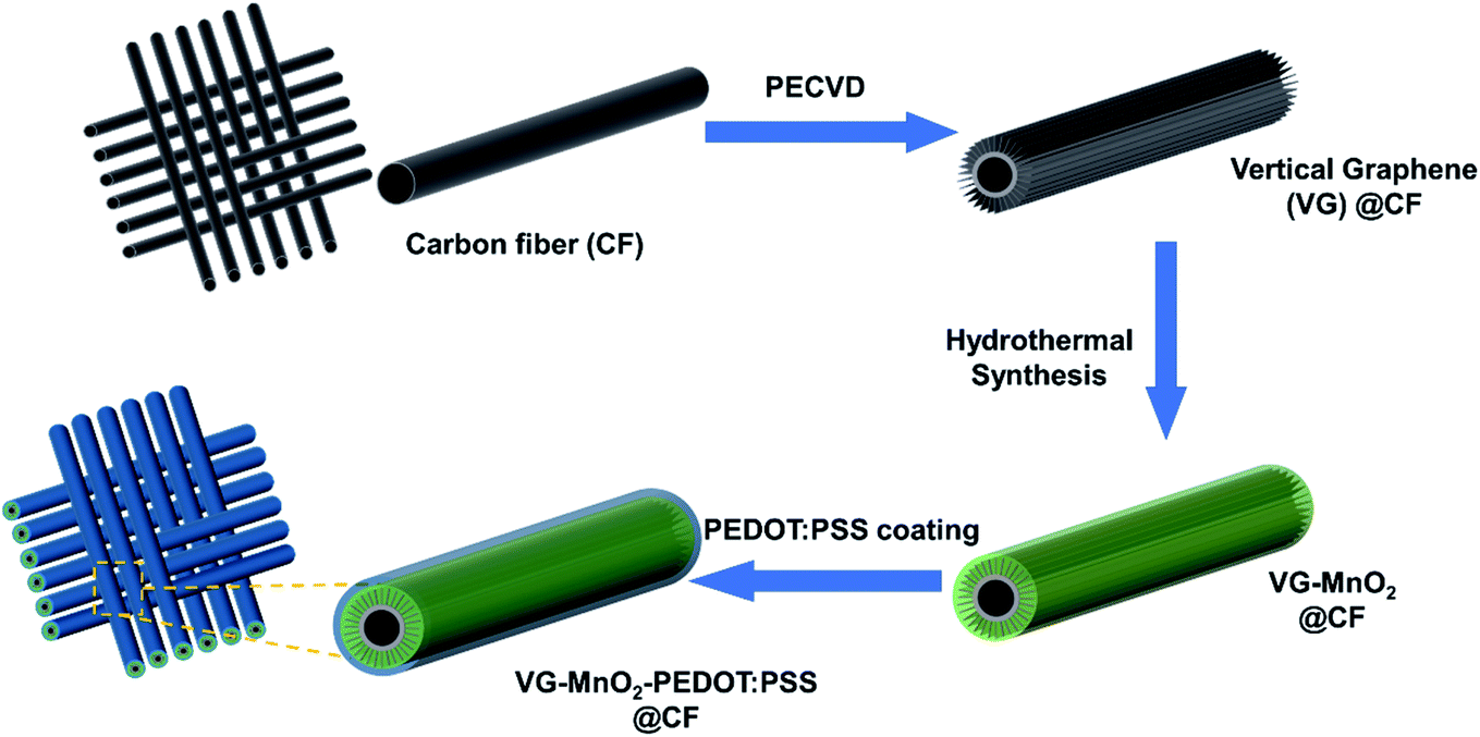 | ||
| Fig. 1 Schematic illustration of the fabrication approach for the VMP cathode. | ||
2.2 Electrochemical measurements
Electrochemical measurements of the electrodes were carried out using an electrochemical workstation (Biologic VSP potentiostat) and NEWARE Battery Test System. Measurements of the aqueous and quasi-solid-state Zn–VMP batteries were performed using a two-electrode configuration.2.3 Materials characterization
The morphology and microstructure of the electrodes were characterized using a field-emission scanning electron microscopy (FEI Nova SEM450) and a 200 kV field emission TEM (Phillips CM200). The cross-section of the VMP cathode was first cut using a Dual Beam Focus Ion Beam (FIB, Nova NanoLab200), and then imaged at an angle of 52° on the SEM. The crystalline structures of MnO2 were analyzed with X-ray thin film diffraction patterns (XRD, Empyrean I). Raman spectroscopy tests were conducted using a Renishaw inVia Raman spectrometer. Mechanical tensile tests were performed on an Instron Universal Testing Machine (Model 3369).3. Results and discussion
The typical 3D morphology of pristine VGs grown on the CF surface is shown in Fig. 2a acquired using scanning electron microscopy (SEM). The high-resolution scanning electron microscope (HRSEM, Fig. 2a inset) image indicates that the thickness of the VG nanosheets ranged from 1 to 5 nm, which is in good agreement with previous findings.32 The pores surrounded by graphene nanosheets are in the range of 50–500 nm, implying a microscopic 3D porous structure that is an excellent host for the subsequent MnO2 deposition. After mild in situ hydrothermal reactions, the MnO2 nanoparticles were attached to the networks of the VGs, thereby occupying the porous interspace of the graphene nanosheets to produce the VM cathode. The highly conductive VGs, which resemble a nano-maze normal to the carbon fibers, act as an interconnected 3D structure enabling fast electron transfer, hence improving the reaction kinetics of the zinc ion intercalation inside the MnO2 interlayer. Furthermore, to mitigate the dissolution of manganese into the electrolyte during cycling, and to further strengthen the VG-MnO2 nanostructure, a layer of an ionically conductive polymer, PEDOT:PSS, was uniformly coated on the VM electrode to yield the VMP cathode as shown in Fig. 2b. The microstructure of the VMP cathode is also evident in the cross-sectional SEM image, as shown in Fig. 2c. As depicted, a cross-section of the VMP cathode, milled using a focused-ion beam, reveals the multilayer structure of the electrode: solid CFs with a buffer layer of amorphous carbon, on which lie the radially orientated VG nanosheets with a height of 5–7 μm containing MnO2 nanoparticles. The outer surface is a layer of PEDOT:PSS. The energy dispersive spectroscopy (EDS) mapping images shown in Fig. 2d and e clearly verify the consistent distribution of Mn, O, C, and S elements, confirming the composition of the VMP cathode and the uniform encapsulation of the PEDOT:PSS layer. This is also confirmed by the EDS line scan and the EDS element spectrum of the bright-field image obtained in the TEM (Fig. S1a–c†), and the low-angle annular dark-field mapping results (Fig. S2a and b†).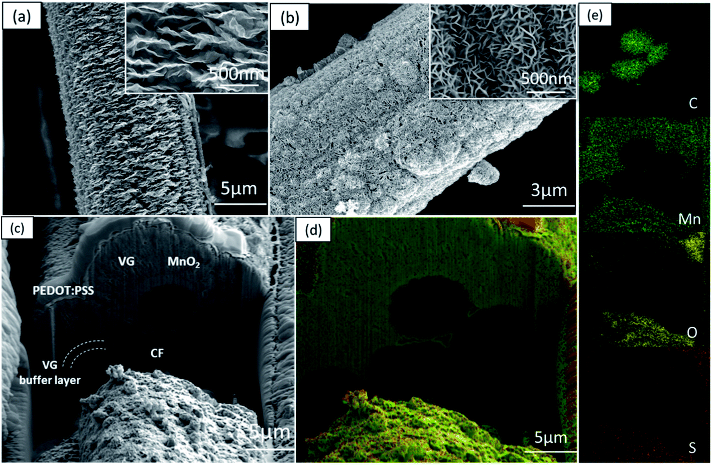 | ||
| Fig. 2 SEM images of (a) VG@CF and (b) VMP cathodes. (c) SEM cross-sectional image of the VMP cathode. EDS mapping images of (d) VMP cathode, and (e) individual mapping of C, Mn, O, and S elements in the VMP cathode. | ||
The lattice structure of the VMP cathode was further characterized by TEM. As shown in Fig. 3a, the pristine VGs appear to have approximately ten graphitic layers, where highly dense MnO2 nanoparticles are grafted onto the basal plane of the graphene nanosheets. The MnO2 nanoparticles are well dispersed without agglomeration, and their crystalline structure is well defined according to the HRTEM images, as shown in the Fig. 3a inset. The HRTEM images indicate a series of lattice fringes, with two discrete spacings of 0.35 nm and 0.23 nm. The former corresponds to the (002) plane of graphene,33 and the latter is consistent with the (211) plane of α-type MnO2 (JCPDS card no. 44-0141).34 It is worth noting that no apparent crystalline feature was detected for the amorphous PEDOT:PSS grains. The microscopic characteristics suggest that the graphene nanosheets are intertwined with the MnO2 nanoparticle layers, confirming the implantable structure of the VMP cathode. Furthermore, the typical concentric circles in the selected area electron diffraction (SAED) pattern of the VMP cathode (Fig. S2c†) verify the polycrystalline nature of the MnO2. To further investigate the mass loading of the MnO2 nanoparticles grown on the VG-grafted carbon fiber fabric, thermogravimetric analysis (TGA) was performed on both the VMP electrode and VG@CF fabric (without MnO2). As shown in Fig. S3,† the mass of the VG@CF fabric decreased dramatically at approximately 650 to 750 °C because of the combustion of the graphitized carbon in the air atmosphere; combustion completed at 800 °C with zero residues. By contrast, the TGA curve of the VMP electrode indicated that the initial reaction temperature was significantly lower due to the catalytic effect of the MnO2 material. After the combustion process was completed, the remaining weight percentage was measured to be about 16.1%, which corresponds to the mass of Mn2O3 particles;35 hence the areal density of MnO2 was determined to be 3.60 mg cm−2.
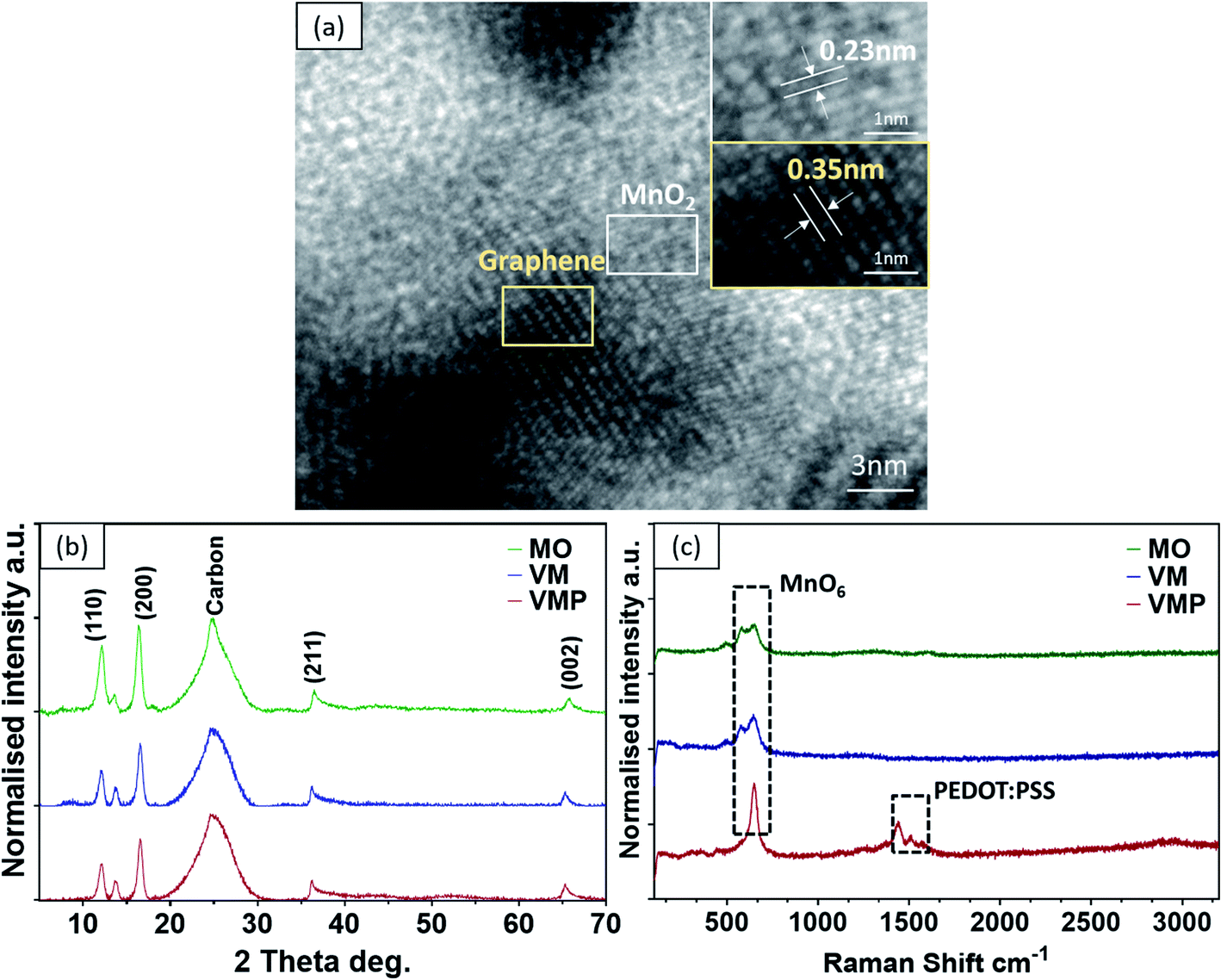 | ||
| Fig. 3 (a) HR-TEM of the VMP cathode. (b) XRD of MO, VM, and VMP cathodes. (c) Raman spectra of MO, VM, and VMP cathodes. | ||
To examine the effects of synthesis and deposition processes on the crystalline microstructure of the active material MnO2, the as-fabricated pristine MnO2@CF (MO), VM, and VMP electrodes were further investigated using X-ray diffraction (XRD) and Raman spectroscopy. It is important to note that all samples share similar peaks, demonstrating that the crystalline structure of MnO2 remains unchanged after combining with the graphene nanosheets and the PEDOT:PSS coating, as shown in Fig. 3b. Specifically, the diffraction peak at about 25° corresponds to the (002) plane for the pristine CF and VGs. Additionally, according to the tetragonal crystalline phase structure of α-type MnO2 (JCPDS card no. 44-0141), the diffraction peaks at 2θ of 12.4°, 17.6°, 37.5°, and 64.8° can be indexed to the planes (110), (200), (211), and (002) respectively. The weaker and broader diffraction peaks between the (211) and (002) planes indicate the limited crystalline domains of α-MnO2. No peaks are observed for the PEDOT:PSS coating due to its amorphous nature, which agrees with the previous HRTEM result. Furthermore, the Raman spectra of these samples, which are shown in Fig. 3c, confirm the two prominent peaks at 580 cm−1 and 650 cm−1 ascribed to the Mn–O symmetric stretching vibration of the MnO6 octahedron in the MO and VM cathodes. Interestingly, only one sharp peak at ∼650 cm−1 is observed, and a new Raman band at 1425 cm−1 in the higher band range corresponds to the appearance of the PEDOT:PSS coating in the VMP sample.
To understand the contributions of the graphene nanosheets and the PEDOT:PSS layer to the charge kinetics of the VMP electrode, the electrochemical characteristics of MO, VM, and VMP cathodes were evaluated by using an electrodeposited Zn@CF anode (Fig. S4c and d†) in an aqueous electrolyte containing 1 M ZnSO4 and 0.1 M MnSO4. It is worth noting that a small amount of MnSO4 in the aqueous electrolyte helps suppress the dissolution of Mn in the electrode.20Fig. 4a compares the cyclic voltammogram (CV) of the VM and VMP samples at a scan rate of 0.5 mV s−1 in a voltage range of 0.8–1.9 V vs. Zn2+/Zn. Two separate redox peaks at 1.15–1.16 and 1.25–1.26 V versus Zn2+/Zn are well observed on cathodic sweeping, corresponding to a two-step reaction. Specifically, the MnO2 cathode experiences a stepwise H+ and Zn2+ insertion/extraction process.7,20,36 All cathodes exhibit similar oxidation/reduction peaks during the anodic/cathodic sweeping, suggesting that the VGs and PEDOT:PSS coating did not affect the redox reaction of MnO2. Nevertheless, the magnitude of the current density obtained from the MO cathode is significantly lower than those of the VM and VMP cathodes, evidencing the effectiveness of the VG network in boosting charge kinetics. The existence of graphene nanosheets endows both the VM and VMP cathodes with larger curve areas, with the VMP cathode exhibiting the highest current peaks, indicating the most superior capacity among the electrodes.
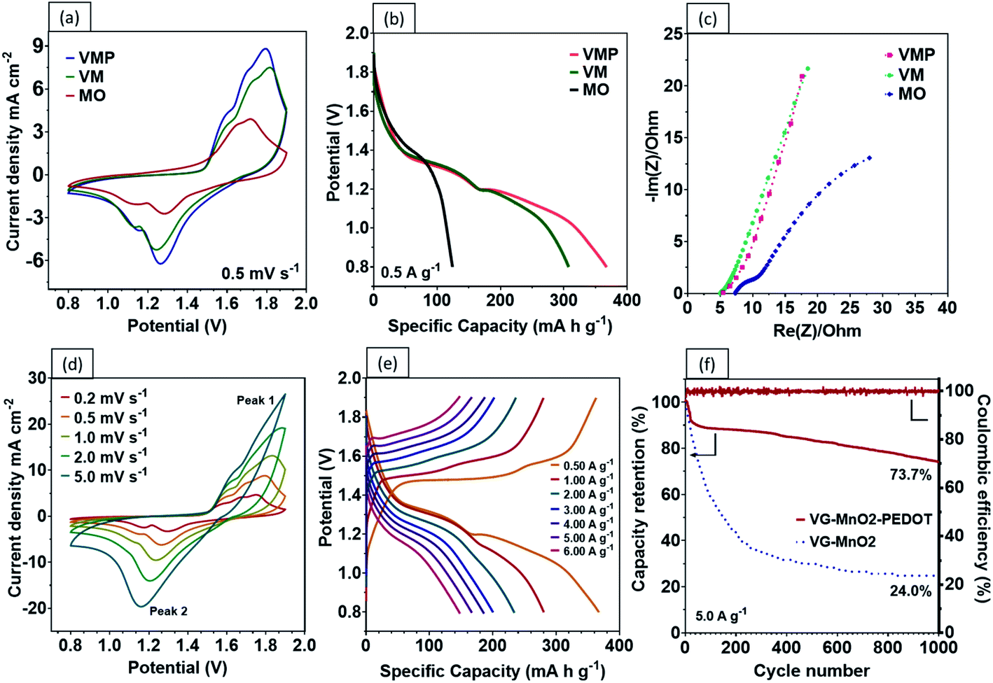 | ||
| Fig. 4 (a) CV curves of VMP, VM, and MO cathodes. (b) GCD profiles of VMP, VM, and MO cathodes. (c) Nyquist plots of VMP, VM, and MO cathodes. (d) CV curves of the VMP sample at different scan rates. (e) GCD curves of the VMP sample at different current densities. (f) Cycling performance comparison of VMP and VM cathodes and coulombic efficiency of the VMP sample. | ||
A comparison of the GCD profiles at a current density of 0.5 A g−1 is shown in Fig. 4b. The VM electrode exhibits two prolonged plateaus demonstrating a total specific capacity of 307 mA h g−1, which is attributed to the H+ and Zn2+ insertion process.7 Encouragingly, the second voltage plateau is further extended by the addition of the protective PEDOT:PSS coating, which results in an excellent specific capacity of 367.4 mA h g−1 at 0.5 A g−1. The charge contribution from the PEDOT:PSS is considered negligible (Fig. S5†) and is consistent with existing literature.37 In contrast, the two plateaus in the MO electrode are merged due to the higher ohmic polarization without the VG-PEDOT:PSS 3D conductive network, resulting in a lower capacity of 124 mA h g−1. The energy density achieved by the VMP electrode is beyond the limit of the theoretical specific capacity of MnO2 in the traditional sense (i.e., via single electron transfer). This surprising phenomenon has been noted recently to stem from multi-oxidation states (Mn2+ and Mn3+) following the Zn ion insertion during the discharge process; as a result, the precise quantities of Mn in the various states are difficult to determine.6,38–40
The reaction mechanisms of these electrodes are further investigated by comparing the electrochemical impedance spectroscopy (EIS) measurements. The corresponding Nyquist plots and equivalent circuit models are shown in Fig. 4c. It is found that the charge transfer and diffusion resistance of the VM and VMP electrodes are lower than those of the MO electrode. Both the VM and VMP electrodes have a lower series resistance (RΩ) (∼5.0 ohm) than the MO electrode (∼7.5 ohm). The distinct RΩ differences between the MO and VM/VMP electrodes indicate a reduction of the internal resistance and enhanced conductivity due to the graphene nanosheets. The slope of the Nyquist plots in Fig. 4c in the low-frequency range relates to the ion diffusion resistance: a higher slope indicates a faster ion diffusion rate and better capacitive behavior. Both VM and VMP electrodes, as shown in Fig. 4c, exhibit steeper slopes than the MO electrode, confirming that the graphene nanosheets significantly improved the ion diffusion efficiency.
One of the biggest drawbacks of MnO2 as an electrode material is its poor electrical conductivity, which is further exacerbated by the addition of an insulating binder (e.g., polyvinylidene difluoride (PDVF)) in conventional fabrication processes. Our results show that by grafting vertical graphene on the surface of carbon fibers to provide interconnected, electrically conductive paths, faster charge and Zn2+ transfers can be achieved. Encouragingly, the CV curves of the VMP electrode reveal typically well-defined redox couples at differing voltage scan rates, reflecting the highly reversible redox reaction of the battery, as shown in Fig. 4d. The current response plots at peak 1 and peak 2 from the previous Fig. 4d, where the b values were calculated to be 0.538 and 0.612 are shown in Fig. S6,† respectively. The results indicate that the corresponding reactions in the VMP electrode predominantly come from the diffusion-controlled process. Moreover, the VMP sample demonstrates exceptional capacity performance at various current densities as shown by the GCD curves (Fig. 4e), which confirms an incredibly high discharge capacity of 367.4 mA h g−1 at 0.5 A g−1, while exhibiting an outstanding rate performance of 280.5, 234.0, 200.4, 186.2, 166.9 and 148.2 mA h g−1 at current densities of 1 to 6 A g−1 (Fig. 5a). The novel VMP cathode outperforms most of the ZIB cathodes reported in the recent literature in terms of its unprecedented high specific capacity and outstanding rate performance. The results obtained from the VMP cathode substantially surpass those of other state-of-the-art ZIB cathodes at comparable current densities, as shown in Fig. 5b, including CNT/α-MnO2 (299 mA h g−1 at 0.6 A g−1),41 α-MnO2 nanofibers (260 mA h g−1 at 0.38 A g−1),20 β-MnO2 nanorods (312 mA h g−1 at 0.033 A g−1),42 pyrolusite β-MnO2 (198 mA h g−1 at 0.3 A g−1),43 layered MnO2 (289 mA h g−1 at 0.05 A g−1),44 Co3O4 nanosheets (162 mA h g−1 at 1.0 A g−1),45 and NaV3O8 nanobelts (276 mA h g−1 at 0.5 A g−1).46
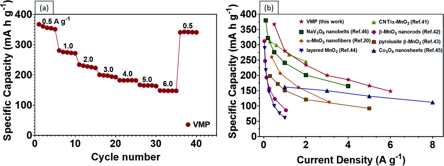 | ||
| Fig. 5 (a) Rate performance of the VMP sample. (b) Comparison of recent MnO2 based cathodes and other ZIB cathodes reported in the literature, as indicated by the reference numbers. | ||
The poor cycling stability of Zn–MnO2 batteries is another major issue inhibiting their practical implementation in wearable electronics.47 Specifically, owing to the Jahn–Teller effect, the Mn in the electrode tends to dissolve in the electrolyte during the discharge process, as represented in eqn (1) and (2). Notably, the Jahn–Teller distortion occurring in the Mn3+ can cause asymmetric deformation in the crystalline structure, which is related to the cycling deterioration of the MnO2 cathode and leads to poor cycling performance.
| Mn4+(s) + e− → Mn3+(s) | (1) |
| 2Mn3+(s) → Mn4+(s) + Mn2+(aq) | (2) |
The PEDOT:PSS coating layer has been found to appreciably mitigate the dissolution of Mn. As shown in Fig. S8,† significant cracking and exfoliation of the VM electrode were observed after 1000 cycles. By comparison, the VMP electrode stayed almost completely intact after 1000 cycles, with only minimal tearing on the surface. The cycling performance of the VMP and VM electrodes is compared in Fig. 4f. The VMP electrode demonstrates outstanding cycling stability, with approximately 73.7% capacity retention after 1000 cycles. By contrast, the retention percentage of VM electrodes without the PEDOT:PSS protective layer rapidly decreases during the first 200 cycles and continues to gradually reduce to 24.0% capacity retention after 1000 cycles.
Recent developments in wearable electronics have heightened the demand for energy storage devices of high flexibility.48,49 Flexible energy storage devices have the potential to leak electrolytes if their protective casing is damaged during repeated bending. In this case, aqueous-based ZIBs will be safer than other batteries, including LIBs, which require toxic organic electrolytes.50 In comparison with liquid electrolytes, a quasi-solid-state electrolyte offers the following advantages. Firstly, a quasi-solid-state electrolyte possesses significantly higher mechanical durability. Secondly, it reduces the risks of electrolyte leakage under repeated deformations. Lastly, it limits the formation of dendrites and the dissolution of active materials.51,52 As a proof of concept, a high performance flexible quasi-solid-state Zn–MnO2 battery was fabricated by sandwiching polyvinyl alcohol (PVA) gel electrolyte between a VMP cathode and Zn anode (Fig. 6a). As shown in Fig. 6b, the CV curves of the fabricated quasi-solid-state Zn–VMP battery at various current densities exhibit similar shapes to those tested in aqueous electrolytes, indicating that the desirable Zn2+ insertion/desertion behavior in the VMP cathode is maintained in the quasi-solid-state environment. Furthermore, this quasi-solid-state Zn–VMP battery displays an excellent capacity of 299.3 mA h g−1 at 0.5 A g−1, as demonstrated by the GCD curve (Fig. 6c). It is worth noting that when compared to the aqueous electrolyte based devices, polymer gel electrolytes incur a slight penalty in rate performance due to their lower ionic conductivity than liquid electrolytes (Fig. S7†). Encouragingly, as shown in Fig. 6d, our quasi-solid-state Zn–VMP battery has achieved promising long-term electrochemical stability with around 68.2% capacity retention and approximately 100% coulombic efficiency recorded after 1000 cycles. Therefore, the quasi-solid-state Zn–VMP battery outperforms most of the current flexible quasi-solid-state ZIBs in terms of electrochemical stability.53–55 Moreover, as shown in Table S1,† the maximum energy density that the quasi-solid-state Zn–VMP battery can achieve is 400.2 W h kg−1 (18.01 mW h cm−3) at a power density of 0.68 kW kg−1 (0.03 W cm−3). In addition, it is capable of a peak power density of 10.1 kW kg−1 (0.46 W cm−3) with an energy density of 106.8 W h kg−1 (4.81 mW h cm−3). These results substantially outperform those of recently reported flexible batteries and supercapacitors, as shown in Fig. 7a, including a Zn2V2O7–Zn battery (114 W h kg−1, 3.2 kW kg−1),56 a HCC-V3S4–Zn battery (155.7 W h kg−1, 5.0 kW kg−1),57 a MnO–Zn battery (383.9 W h kg−1, 0.1 kW kg−1),58 a δ-MnO2–Zn battery (130 W h kg−1, 7.7 kW kg−1),59 a β-MnO2–Zn battery (110 W h kg−1, 5.9 kW kg−1),60 a N-CNSs@MnO2–Zn battery (352.5 W h kg−1, 0.5 kW kg−1),61 a MnO2-HPC supercapacitor (49.8 W h kg−1, 0.3 kW kg−1),62 a CuO@MnO2 supercapacitor (29.9 W h kg−1, 0.3 kW kg−1),63 and a Bi2O3–MnO2 supercapacitor (11.3 W h kg−1, 3.4 kW kg−1).64
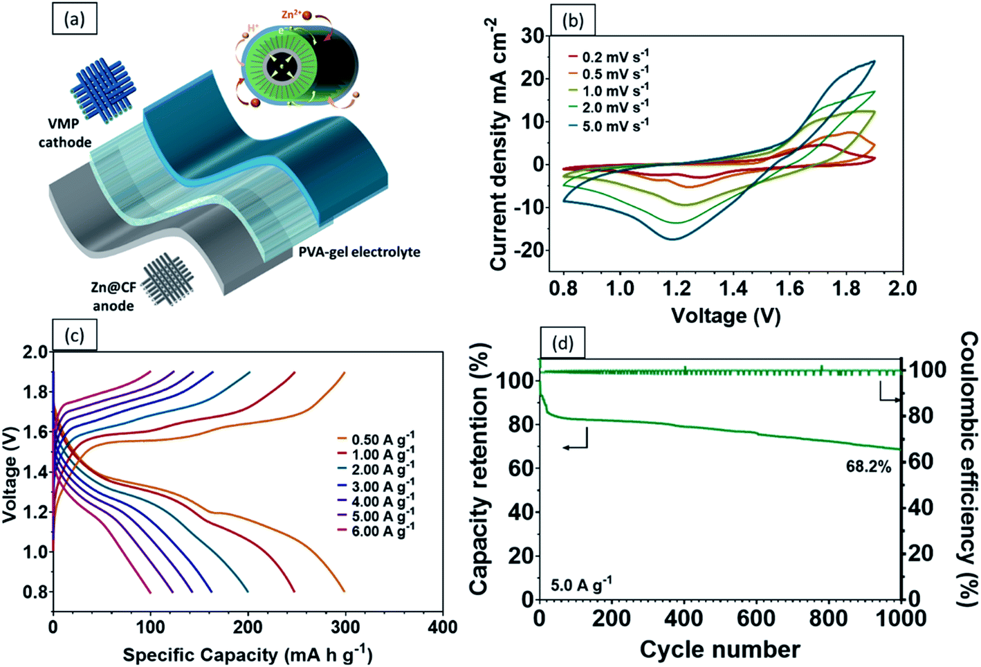 | ||
| Fig. 6 (a) Schematic illustration of a flexible quasi-solid-state Zn–VMP battery. (b) CV curves of the quasi-solid-state Zn–VMP battery. (c) GCD profiles of the quasi-solid-state Zn–VMP battery. (d) Cycling performance and coulombic efficiency of the quasi-solid-state Zn–VMP battery. | ||
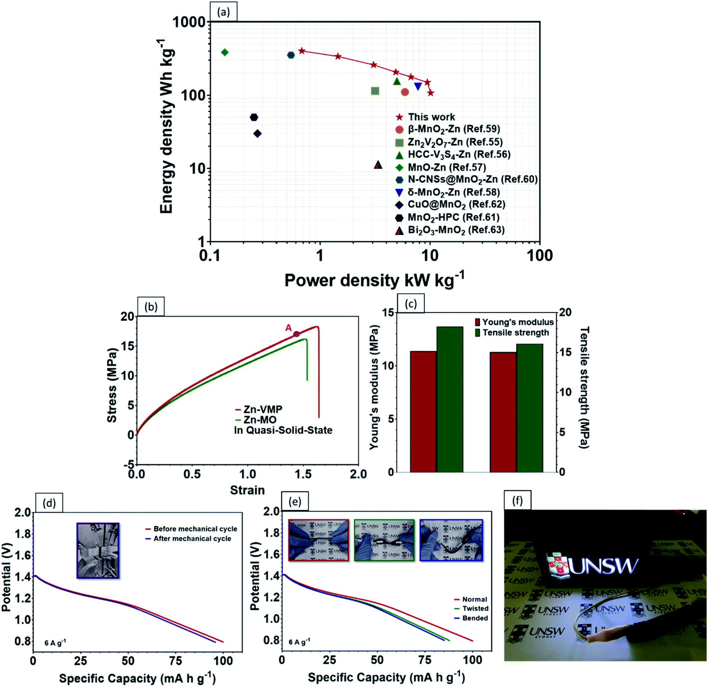 | ||
| Fig. 7 (a) Ragone plot comparing other state-of-the-art ZIBs and supercapacitors. (b) Stress–strain profiles of the Zn–VMP vs. MO–Zn battery in a quasi-solid-state, noting that point A is at 80% of the ultimate tensile strength for the Zn–VMP battery. (c) The comparison of Young's modulus and tensile strength of the Zn–VMP and MO–Zn battery. Galvanostatic discharge curves of (d) the comparison of before vs. after the mechanical cycling, and (e) under different deformation conditions for the Zn–VMP battery. (f) Photograph of a neon sign made with LED light powered by two quasi-solid-state Zn–VMP batteries in series. | ||
The mechanical properties and durability of flexible batteries are some of the critical challenges facing the practical application of wearable electronic devices. Very few reports have discussed the mechanical properties of quasi-solid-state energy storage devices, which are critical for developing a practical design for wearable electronics. To this end, the tensile properties of the quasi-solid-state Zn–VMP battery were characterized, including the static strength and the effect of repeated mechanical deformation representative of actual wearing scenarios, on the electrochemical performance of the battery. The battery's electrochemical performance was measured while being subjected to different levels of mechanical loading. As shown in Fig. 7b, both the Zn–VMP battery and the Zn-MO battery with the quasi-solid-state electrolyte share similar stress–strain curves, which indicate comparable behaviors under mechanical loading. The tensile results are shown in Fig. 7c. Both batteries show a similar Young's modulus of about 11.4 MPa, while the Zn–VMP battery displays slightly higher strength (18.3 MPa) compared to the Zn-MO battery (16.1 MPa). The quasi-solid-state Zn–VMP battery was further subjected to a hundred cycles of repeated mechanical tensile stretching from 0 to 80% of its ultimate tensile strength. Encouragingly, the battery retained its initial electrochemical performance following mechanical cycling, with minimal electrochemical degradation, as shown in Fig. 7d. Moreover, the battery, due to its solid-state design, exhibited exceptional flexibility to repeated deformations, including twisting and bending, without significant change in the discharge performance (Fig. 7e). To demonstrate how the quasi-solid-state Zn–VMP battery performs in a real application, a neon sign including a 3 V light-emitting diode (LED) was driven by two Zn–VMP batteries connected in series, as shown in Fig. 7f. The successful demonstration of the quasi-solid-state Zn–VMP battery as a flexible energy storage device provides great potential for future wearable electronics.
4. Conclusion
In summary, we have designed and successfully fabricated a novel VMP electrode consisting of carbon fibers with vertical graphene, MnO2, and PEDOT:PSS. In this electrode, the carbon fibers act as the load-carrying conductor, the vertical graphene enhances the charge kinetics of MnO2, and the ion conductive PEDOT:PSS coating suppresses dissolution and damage of MnO2 during repeated electrical and mechanical cycling. This new electrode demonstrates exceptional performance as a mechanically robust flexible cathode for zinc ion batteries. Compared to a traditional MnO2 electrode, the novel VMP cathode shows significantly higher capacity, outstanding rate capability, and good cycling stability. These exceptional properties stem from the highly conductive VG nanosheets being embedded with MnO2 providing a 3D microstructure that enhances the charge transfer kinetics, the Zn2+ intercalation, and mechanical durability. When used with an aqueous electrolyte and Zn–carbon fiber anode, the novel VMP cathode has been found to deliver a maximum specific capacity of 367.4 mA h g−1 at 0.5 A g−1 with an outstanding capacity retention of approximately 73.7% after 1000 charge/discharge cycles. Furthermore, when this VMP electrode is combined with a quasi-solid-state electrolyte, the resulting flexible battery provides excellent mechanical properties, robust electrochemical performance under cyclic mechanical deformation, and a high energy density of 400.2 W h kg−1. This novel electrode design provides a promising strategy for high-performance flexible ZIBs for future wearable electronics applications.Conflicts of interest
There are no conflicts to declare.Acknowledgements
C. H. Wang and D. Wang would like to acknowledge the financial support of ARC Industry Transformation Research Hub IH180100020. J. Chen would like to thank Yiran Zheng and Yuyan Yu for their technical assistance. The authors acknowledge the facilities and technical assistance from Mark Wainwright Analytical Centre and at the Electron Microscope Unit at UNSW.References
- Z. Wen, M.-H. Yeh, H. Guo, J. Wang, Y. Zi, W. Xu, J. Deng, L. Zhu, X. Wang, C. Hu, L. Zhu, X. Sun and Z. L. Wang, Sci. Adv., 2016, 2, e1600097 CrossRef.
- A. M. Zamarayeva, A. E. Ostfeld, M. Wang, J. K. Duey, I. Deckman, B. P. Lechêne, G. Davies, D. A. Steingart and A. C. Arias, Sci. Adv., 2017, 3, e1602051 CrossRef PubMed.
- J.-M. Tarascon and M. Armand, in Materials for sustainable energy: a collection of peer-reviewed research and review articles from Nature Publishing Group, World Scientific, 2011, pp. 171–179 Search PubMed.
- J. Chang, J. Shang, Y. Sun, L. K. Ono, D. Wang, Z. Ma, Q. Huang, D. Chen, G. Liu and Y. Cui, Nat. Commun., 2018, 9, 1–11 CrossRef PubMed.
- J. F. Parker, C. N. Chervin, I. R. Pala, M. Machler, M. F. Burz, J. W. Long and D. R. Rolison, Science, 2017, 356, 415–418 CrossRef CAS PubMed.
- Y. Zeng, X. Zhang, Y. Meng, M. Yu, J. Yi, Y. Wu, X. Lu and Y. Tong, Adv. Mater., 2017, 29, 1700274 CrossRef PubMed.
- W. Sun, F. Wang, S. Hou, C. Yang, X. Fan, Z. Ma, T. Gao, F. Han, R. Hu and M. Zhu, J. Am. Chem. Soc., 2017, 139, 9775–9778 CrossRef CAS PubMed.
- B. Tang, L. Shan, S. Liang and J. Zhou, Energy Environ. Sci., 2019, 12, 3288–3304 RSC.
- S. Higashi, S. W. Lee, J. S. Lee, K. Takechi and Y. Cui, Nat. Commun., 2016, 7, 11801 CrossRef PubMed.
- M. Song, H. Tan, D. Chao and H. J. Fan, Adv. Funct. Mater., 2018, 28, 1802564 CrossRef.
- K. Wang, X. Zhang, J. Han, X. Zhang, X. Sun, C. Li, W. Liu, Q. Li and Y. Ma, ACS Appl. Mater. Interfaces, 2018, 10, 24573–24582 CrossRef CAS PubMed.
- C. Xu, S. W. Chiang, J. Ma and F. Kang, J. Electrochem. Soc., 2013, 160, A93–A97 CrossRef CAS.
- W. Wei, X. Cui, W. Chen and D. G. Ivey, Chem. Soc. Rev., 2011, 40, 1697–1721 RSC.
- S. Devaraj and N. Munichandraiah, J. Phys. Chem. C, 2008, 112, 4406–4417 CrossRef CAS.
- O. Ghodbane, J.-L. Pascal and F. Favier, ACS Appl. Mater. Interfaces, 2009, 1, 1130–1139 CrossRef CAS PubMed.
- S. W. Lee, B.-S. Kim, S. Chen, Y. Shao-Horn and P. T. Hammond, J. Am. Chem. Soc., 2009, 131, 671–679 CrossRef CAS PubMed.
- W. Liu, R. Yin, X. Xu, L. Zhang, W. Shi and X. Cao, Adv. Sci., 2019, 6, 1802373 CrossRef PubMed.
- J. Huang, Z. Wang, M. Hou, X. Dong, Y. Liu, Y. Wang and Y. Xia, Nat. Commun., 2018, 9, 1–8 CrossRef PubMed.
- T. Xiong, Z. G. Yu, H. Wu, Y. Du, Q. Xie, J. Chen, Y. W. Zhang, S. J. Pennycook, W. S. V. Lee and J. Xue, Adv. Energy Mater., 2019, 9, 1803815 CrossRef.
- H. Pan, Y. Shao, P. Yan, Y. Cheng, K. S. Han, Z. Nie, C. Wang, J. Yang, X. Li and P. Bhattacharya, Nat. Energy, 2016, 1, 1–7 Search PubMed.
- X. Zhang, S. Wu, S. Deng, W. Wu, Y. Zeng, X. Xia, G. Pan, Y. Tong and X. Lu, Small Methods, 2019, 1900525, DOI:10.1002/smtd.201900525.
- Q. Li, J. Liu, J. Zou, A. Chunder, Y. Chen and L. Zhai, J. Power Sources, 2011, 196, 565–572 CrossRef CAS.
- G. Yu, L. Hu, N. Liu, H. Wang, M. Vosgueritchian, Y. Yang, Y. Cui and Z. Bao, Nano Lett., 2011, 11, 4438–4442 CrossRef CAS PubMed.
- R. I. Jafri, A. K. Mishra and S. Ramaprabhu, J. Mater. Chem., 2011, 21, 17601–17605 RSC.
- Q. Lu and Y. Zhou, J. Power Sources, 2011, 196, 4088–4094 CrossRef CAS.
- F. Wang, O. Borodin, T. Gao, X. Fan, W. Sun, F. Han, A. Faraone, J. A. Dura, K. Xu and C. Wang, Nat. Mater., 2018, 17, 543–549 CrossRef CAS PubMed.
- C. Shen, X. Li, N. Li, K. Xie, J.-g. Wang, X. Liu and B. Wei, ACS Appl. Mater. Interfaces, 2018, 10, 25446–25453 CrossRef CAS PubMed.
- Z. J. Han, S. Pineda, A. T. Murdock, D. H. Seo, K. Ostrikov and A. Bendavid, J. Mater. Chem. A, 2017, 5, 17293–17301 RSC.
- S. Duan, K. Yang, Z. Wang, M. Chen, L. Zhang, H. Zhang and C. Li, ACS Appl. Mater. Interfaces, 2016, 8, 2187–2192 CrossRef CAS PubMed.
- M. Chen, L. Zhang, S. Duan, S. Jing, H. Jiang and C. Li, Adv. Funct. Mater., 2014, 24, 7548–7556 CrossRef CAS.
- Q. Guan, Y. Li, X. Bi, J. Yang, J. Zhou, X. Li, J. Cheng, Z. Wang, B. Wang and J. Lu, Adv. Energy Mater., 2019, 9, 1901434 CrossRef CAS.
- Z. Bo, S. Mao, Z. J. Han, K. Cen, J. Chen and K. K. Ostrikov, Chem. Soc. Rev., 2015, 44, 2108–2121 RSC.
- F. Yang, L. Zhang, A. Zuzuarregui, K. Gregorczyk, L. Li, M. Beltran, C. Tollan, J. Brede, C. Rogero and A. Chuvilin, ACS Appl. Mater. Interfaces, 2015, 7, 20513–20519 CrossRef CAS PubMed.
- K. Kim, G. Daniel, V. G. Kessler, G. A. Seisenbaeva and V. G. Pol, Nanomaterials, 2018, 8, 608 CrossRef PubMed.
- R. K. Sharma, H.-S. Oh, Y.-G. Shul and H. Kim, Phys. B, 2008, 403, 1763–1769 CrossRef CAS.
- N. Zhang, F. Cheng, Y. Liu, Q. Zhao, K. Lei, C. Chen, X. Liu and J. Chen, J. Am. Chem. Soc., 2016, 138, 12894–12901 CrossRef CAS PubMed.
- D. Chao, X. Xia, J. Liu, Z. Fan, C. F. Ng, J. Lin, H. Zhang, Z. X. Shen and H. J. Fan, Adv. Mater., 2014, 26, 5794–5800 CrossRef CAS PubMed.
- M. H. Alfaruqi, J. Gim, S. Kim, J. Song, J. Jo, S. Kim, V. Mathew and J. Kim, J. Power Sources, 2015, 288, 320–327 CrossRef CAS.
- S. Wu, Y.-F. Wang, W.-L. Liu, M.-M. Ren, F.-G. Kong, S.-J. Wang, X.-Q. Wang, H. Zhao and J.-M. Bao, Inorg. Chem. Front., 2018, 5, 3067–3073 RSC.
- C. Wang, M. Wang, Z. He, L. Liu and Y. Huang, ACS Appl. Energy Mater., 2020, 3, 1742–1748 CrossRef CAS.
- D. Wang, H. Li, Z. Liu, Z. Tang, G. Liang, F. Mo, Q. Yang, L. Ma and C. Zhi, Small, 2018, 14, 1803978 CrossRef PubMed.
- S. Islam, M. H. Alfaruqi, V. Mathew, J. Song, S. Kim, S. Kim, J. Jo, J. P. Baboo, D. T. Pham and D. Y. Putro, J. Mater. Chem. A, 2017, 5, 23299–23309 RSC.
- X. Zhang, Z. Wu, X. Zhang, L. Li, Y. Li, H. Xu, X. Li, X. Yu, Z. Zhang and Y. Liang, Nat. Commun., 2017, 8, 1–8 CrossRef PubMed.
- M. H. Alfaruqi, S. Islam, D. Y. Putro, V. Mathew, S. Kim, J. Jo, S. Kim, Y.-K. Sun, K. Kim and J. Kim, Electrochim. Acta, 2018, 276, 1–11 CrossRef CAS.
- X. Wang, F. Wang, L. Wang, M. Li, Y. Wang, B. Chen, Y. Zhu, L. Fu, L. Zha and L. Zhang, Adv. Mater., 2016, 28, 4904–4911 CrossRef CAS PubMed.
- F. Wan, L. Zhang, X. Dai, X. Wang, Z. Niu and J. Chen, Nat. Commun., 2018, 9, 1–11 CrossRef CAS PubMed.
- S. Zhao, B. Han, D. Zhang, Q. Huang, L. Xiao, L. Chen, D. G. Ivey, Y. Deng and W. Wei, J. Mater. Chem. A, 2018, 6, 5733–5739 RSC.
- J. Zhao, K. K. Sonigara, J. Li, J. Zhang, B. Chen, J. Zhang, S. S. Soni, X. Zhou, G. Cui and L. Chen, Angew. Chem., 2017, 129, 7979–7983 CrossRef.
- C. Chen, J. Cao, Q. Lu, X. Wang, L. Song, Z. Niu and J. Chen, Adv. Funct. Mater., 2017, 27, 1604639 CrossRef.
- P. Hiralal, S. Imaizumi, H. E. Unalan, H. Matsumoto, M. Minagawa, M. Rouvala, A. Tanioka and G. A. Amaratunga, ACS Nano, 2010, 4, 2730–2734 CrossRef CAS PubMed.
- W. Huang, Z. Zhu, L. Wang, S. Wang, H. Li, Z. Tao, J. Shi, L. Guan and J. Chen, Angew. Chem., Int. Ed., 2013, 52, 9162–9166 CrossRef CAS PubMed.
- X. Hu, Z. Li, Y. Zhao, J. Sun, Q. Zhao, J. Wang, Z. Tao and J. Chen, Sci. Adv., 2017, 3, e1602396 CrossRef PubMed.
- B. He, Q. Zhang, L. Li, J. Sun, P. Man, Z. Zhou, Q. Li, J. Guo, L. Xie and C. Li, J. Mater. Chem. A, 2018, 6, 14594–14601 RSC.
- W. Lai, Y. Wang, Z. Lei, R. Wang, Z. Lin, C.-P. Wong, F. Kang and C. Yang, J. Mater. Chem. A, 2018, 6, 3933–3940 RSC.
- Y. Zeng, X. Zhang, Y. Meng, M. Yu, J. Yi, Y. Wu, X. Lu and Y. Tong, Adv. Mater., 2017, 29, 1700274 CrossRef PubMed.
- B. Sambandam, V. Soundharrajan, S. Kim, M. H. Alfaruqi, J. Jo, S. Kim, V. Mathew, Y.-k. Sun and J. Kim, J. Mater. Chem. A, 2018, 6, 3850–3856 RSC.
- S. Liu, X. Chen, Q. Zhang, J. Zhou, Z. Cai and A. Pan, ACS Appl. Mater. Interfaces, 2019, 11, 36676–36684 CrossRef CAS PubMed.
- C. Zhu, G. Fang, S. Liang, Z. Chen, Z. Wang, J. Ma, H. Wang, B. Tang, X. Zheng and J. Zhou, Energy Storage Materials, 2020, 24, 394–401 CrossRef.
- D. Wang, L. Wang, G. Liang, H. Li, Z. Liu, Z. Tang, J. Liang and C. Zhi, ACS Nano, 2019, 13, 10643–10652 CrossRef CAS PubMed.
- N. Zhang, F. Cheng, J. Liu, L. Wang, X. Long, X. Liu, F. Li and J. Chen, Nat. Commun., 2017, 8, 1–9 CrossRef.
- Y. Zhang, S. Deng, Y. Li, B. Liu, G. Pan, Q. Liu, X. Wang, X. Xia and J. Tu, Energy Storage Materials, 2020, 29, 52–59 CrossRef.
- H. Li, L. Jiang, Q. Cheng, Y. He, V. Pavlinek, P. Saha and C. Li, Electrochim. Acta, 2015, 164, 252–259 CrossRef CAS.
- H. Chen, M. Zhou, T. Wang, F. Li and Y. X. Zhang, J. Mater. Chem. A, 2016, 4, 10786–10793 RSC.
- H. Xu, X. Hu, H. Yang, Y. Sun, C. Hu and Y. Huang, Adv. Energy Mater., 2015, 5, 1401882 CrossRef.
Footnote |
| † Electronic supplementary information (ESI) available. See DOI: 10.1039/d0ta08775k |
| This journal is © The Royal Society of Chemistry 2021 |