High-performance metal–iodine batteries enabled by a bifunctional dendrite-free Li–Na alloy anode†
Donglin
Yu
ab,
Dong
Liu
 a,
Lei
Shi
ab,
Jieshan
Qiu
 *a and
Liming
Dai
 *c
*c
aState Key Laboratory of Organic–Inorganic Composites, Beijing Advanced Innovation Center for Soft Matter Science and Engineering, College of Chemical Engineering, Beijing University of Chemical Technology, Beijing, 100029, China. E-mail: qiujs@mail.buct.edu.cn
bCollege of Materials Science and Engineering, Beijing University of Chemical Technology, Beijing, 100029, China
cAustralian Carbon Materials Centre (A-CMC), School of Chemical Engineering, University of New South Wales, Sydney, NSW 2052, Australia. E-mail: l.dai@unsw.edu.au
First published on 21st October 2020
Abstract
Rechargeable aprotic alkali metal (Li and Na)–iodine (AM–I2) batteries with high theoretical capacity and specific energy density have emerged as one of the promising energy storage technologies. However, their application has been severely limited by dendrite formation on alkali metal anodes. By infusing a eutectic Li–Na alloy into a carbon cloth (CC), we developed a novel bifunctional Li–Na alloy-CC anode for Li/Na–iodine batteries with significantly enhanced electrochemical performance. Specifically, the LiNa-CC anode in a symmetric battery exhibited an ultra-stable cycling stability up to 800 and 1650 hours for Li and Na plating/stripping at a current density of 40 and 20 mA cm−2, respectively. When coupled with an iodine cathode in a Li/Na–iodine battery, the LiNa-CC anode exhibited a significantly improved cycling stability with 84.8% and 83.3% capacity retentions after 2000 cycles at a current density of 5C for Li–I2 and Na–I2 batteries, respectively. This work provides new perspectives for developing multifunctional dendrite-free alkali metal–iodine batteries.
Introduction
Lithium ion batteries (LIBs) have been successfully commercialized for decades, though still facing challenges to meet the ever increasing demand for energy storage in electric vehicles (EVs) and hybrid electric vehicles (HEVs) with high safety.1–4 In the past decade, alkali metal–iodine (AM–I2) batteries5 were considered as one of the most promising next-generation rechargeable batteries because of their high theoretical capacity and specific energy density, and the natural abundance and low cost of iodine. However, it remains a great challenge to develop practical AM–I2 batteries. Owing to their high theoretical capacities6 (3861 and 1166 mA h g−1 for Li and Na, respectively) and low anode potentials7 (Li+/Li: −3.04 V and Na+/Na: −2.71 V vs. standard hydrogen electrode (SHE), respectively), alkali metal8–11 (Li and Na) anodes have emerged as one of the promising candidates to replace traditional anodes (e.g., commercialized graphite). Unfortunately, pure alkali metal anodes often fail for multiple reasons, including huge volume changes,9,12 uncontrolled growth of dendrites,10 and formation of unstable solid electrolyte interphase (SEI) films and cracks,11 which limit their practical applications.Recently, some rational strategies have been developed to address the issues mentioned above and improve the cycling stability of alkali metal plating/stripping. Examples include the use of electrolyte additives,13 artificial solid electrolyte interphase (SEI) films,14–17 self-healing surfaces,18,19 three-dimensional (3D) scaffolds,20–23 carbon hosts,24–26 solid interfaces27–30 and alkali-metal alloys.31–38 In particular, a 3D composite fabricated by infiltrating molten Li into nitrogen-doped graphitic carbon foam (3D Li/NGCF) was demonstrated to suppress the dendrite growth of Li at the nucleation stage.20 A Li amalgam film was devised to afford repeated Li plating/stripping.39 A 3D lithium metal anode prepared by loading molten Li on nitrogen and phosphorous carbon revealed good cycling stability.40 Besides, a Li–Al alloy layer was prepared via in situ electrochemical generation, and it can function as a Li reservoir to compensate the irreversible Li loss.41,42
In addition, alkali-metal-alloy anodes, such as Li–Na alloys and liquid Na–K alloys exhibited good performance in batteries including alkali metal–O2 batteries33,43,52 and Li–Na hybrid batteries.54 Typically, a Li–Na alloy has been employed as a metal anode for Li–Na alloy–O2 batteries;43 for a Li–Na hybrid battery (LNHB) based on a Na metal anode, a LiFePO4 (LFP) cathode and hybrid electrolyte have been demonstrated to be feasible.54 Although these studies have significantly enhanced the stability and cycling performance of alkali metal anodes,38,44–46 which, when used in AM–I2 batteries, still suffer from multiple disadvantages, including the dendrite formation,47,48 shuttle effect49,50 and poor stability for practical applications.51 Encouragingly, these alloy strategies including with Na–K alloys and Li–Na alloys inspired the exploration of highly stable metal anodes for metal–iodine batteries. Of particular importance is that the fundamental electrochemical behaviours of Li–Na alloys in AM–I2 batteries and the interaction of Li/Na and carbon are still unclear,52,53 though Li–Na alloy as a novel alkali metal anode hold great potential for use in AM–I2 batteries.54,55
Herein, we report for the first time that a Li–Na alloy anode supported by a carbon cloth (LiNa-CC), prepared by infusing a molten Li–Na eutectic alloy into 3D carbon fibres within the carbon cloth, can serve as a dendrite-free alkali metal anode in Li/Na–I2 (2Li/Na + I2 ↔ 2LiI/NaI) batteries. By optimizing the molar ratio of Li and Na, a bifunctional LiNa-CC anode with a Li/Na molar ratio of 2![[thin space (1/6-em)]](https://www.rsc.org/images/entities/char_2009.gif) :
:![[thin space (1/6-em)]](https://www.rsc.org/images/entities/char_2009.gif) 1 was obtained for efficient storage of both lithium and sodium.
1 was obtained for efficient storage of both lithium and sodium.
Results and discussion
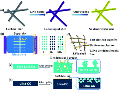
Fig. 1a schematically shows the preparation process for the LiNa-CC metal anode. When the carbon cloth was added into a liquid Li–Na alloy (a Li/Na molar ratio of 2![[thin space (1/6-em)]](https://www.rsc.org/images/entities/char_2009.gif) :
:![[thin space (1/6-em)]](https://www.rsc.org/images/entities/char_2009.gif) 1), the carbon cloth was coated with Li/Na immediately, as indicated by the colour change from black to a silvery colour of the liquid Li–Na alloy (Fig. S1a, ESI†). Gradually, the silvery colour changed to gold in a few seconds after further interaction with Li and Na metals (Fig. S1b, ESI†), indicating the formation of LiC6.30 Owing to the eutectic fusion of the Li and Na alloy crystals, the electrochemical behaviour on the surface of LiNa-CC is different from that of the Li and Na surfaces, respectively (Fig. 1b). As schematically illustrated in (Fig. 1c–e) and we shall see later, the as-developed LiNa-CC electrode has multiple advantages, including fast kinetics, uniform nucleation, a stable SEI layer, and suppression of the dendrite growth.
1), the carbon cloth was coated with Li/Na immediately, as indicated by the colour change from black to a silvery colour of the liquid Li–Na alloy (Fig. S1a, ESI†). Gradually, the silvery colour changed to gold in a few seconds after further interaction with Li and Na metals (Fig. S1b, ESI†), indicating the formation of LiC6.30 Owing to the eutectic fusion of the Li and Na alloy crystals, the electrochemical behaviour on the surface of LiNa-CC is different from that of the Li and Na surfaces, respectively (Fig. 1b). As schematically illustrated in (Fig. 1c–e) and we shall see later, the as-developed LiNa-CC electrode has multiple advantages, including fast kinetics, uniform nucleation, a stable SEI layer, and suppression of the dendrite growth.
Structure of the LiNa-CC electrode
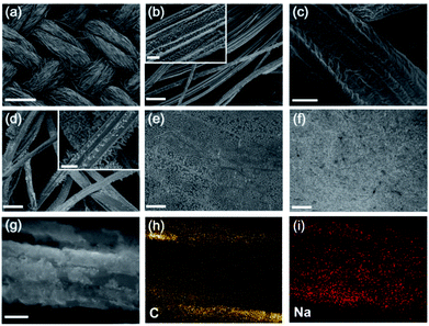
To determine the crystal structure of the LiNa-CC anode, we performed X-ray diffraction (XRD, Fig. S2, ESI†). According to previous reports,54–56 a Li–Na alloy is a eutectic alloy or solid solution, and should show the individual diffraction peaks of Li and Na. Indeed, the XRD results in Fig. S2 (ESI†) show that the Li and Na maintain their individual crystal structures. Moreover, the peak around 37.8° is from the Li–C6 crystal structure,30 revealing the strong interaction of the Li–Na alloy with the carbon matrix. X-ray photoelectron spectroscopy (XPS) spectra of LiNa-CC (Fig. S3a, ESI†) reveal both the Li and Na signals. The high-resolution XPS spectrum of Li 1s (Fig. S3b, ESI†) and Na 1s (Fig. S3c, ESI†) further confirmed the individual crystal structure of LiNa and the successful infusion of Li and Na into the carbon cloth.The morphology of the LiNa-CC electrode was examined by scanning electron microscopy (SEM). Fig. 2a shows the morphology of the carbon cloth, and Fig. 2b reveals the individual carbon fibres of about 8 μm diameter inside of the carbon cloth. After the infusion, Fig. 2c shows a 4 μm thick uniform coating layer of the Li–Na alloy on the carbon fibres in the carbon cloth. In contrast, some atypical particles and rags with a size of around 1–2 μm can be clearly seen on the surface of the Li-CC electrode (Fig. 2d), and they might serve as the nucleation sites for the formation of Li dendrites during the subsequent plating/stripping process.40 For comparison, the SEM images of bare Li and Na foils are also given in Fig. 2e and f, showing a smooth surface. The energy dispersive spectroscopy (EDS) mapping results given in Fig. 2g–i further confirm the homogeneous distribution of Na on the carbon fibres both inside and on the surface of the LiNa-CC anode, though the elemental Li cannot be probed by EDS.
Electrochemical performance of the LiNa-CC electrode in metal–Cu half cells
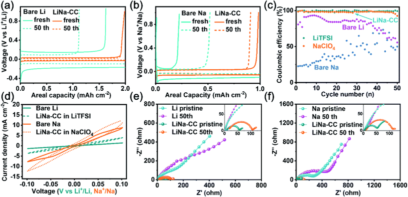
To investigate the electrochemical performance of the LiNa-CC electrode, we first performed galvanostatic plating/stripping tests. Fig. 3 shows the plating/stripping performance of the LiNa-CC electrode in metal–Cu half batteries (LiNa-CC//1 M LiTFSI, DME/DOL//Cu; LiNa-CC//1 M NaClO4, and DME/DOL//Cu). Compared with bare Li (Fig. 3a and c), the LiNa-CC electrode reveals a significantly high reversibility and stability, along with a much lower voltage hysteresis (64 mV vs. 360 mV) and a higher coulombic efficiency (CE, 99.3% vs. 80.7% initially and 99.1% vs. 56.1% after 50 cycles) at a current density of 2 mA cm−2 (2 mA h cm−2). In addition, the LiNa-alloy (Li/Na molar ratio of 2![[thin space (1/6-em)]](https://www.rsc.org/images/entities/char_2009.gif) :
:![[thin space (1/6-em)]](https://www.rsc.org/images/entities/char_2009.gif) 1) electrode exhibits higher voltage hysteresis and lower coulombic efficiency than LiNa-CC (Fig. S4a and c, ESI†), indicating the superiority of the carbon matrix. In NaClO4 (Fig. 3b and c), the LiNa-CC electrode shows an excellent electrochemical performance (ΔV = 86 mV, CE = 98.3% initially and ΔV = 52 mV, CE = 91.2% even after 50 cycles) at 1 mA cm−2 (1 mA h cm−2), surpassing the bare Na and LiNa-alloy anodes (Fig. S4b and c, ESI†). Fig. 3e and f show the electrochemical impedance spectroscopy (EIS) results for the metal–Cu half cells measured in LiTFSI and NaClO4 electrolyte, respectively. As shown in Fig. 3e, the LiNa-CC electrode exhibited a smaller semicircle (charge transfer resistance, Rct) in the high frequency region measured in LiTFSI, indicating a faster charge transfer of Li ions with the LiNa-CC electrode compared to the bare Li electrode. For NaClO4, Fig. 3f shows a similar semicircle and straight line for the EIS spectra of the LiNa-CC and bare Na electrodes. The corresponding numerical data of Rct for different anodes are listed in Table S1 (ESI†). As can be seen, the LiNa-CC electrode exhibits the lowest Rct both in the Li and Na ion electrolytes, indicating superior electrochemical performance to that of the bare Li, bare Na and LiNa-alloy (Fig. S4d, ESI†) electrodes.
1) electrode exhibits higher voltage hysteresis and lower coulombic efficiency than LiNa-CC (Fig. S4a and c, ESI†), indicating the superiority of the carbon matrix. In NaClO4 (Fig. 3b and c), the LiNa-CC electrode shows an excellent electrochemical performance (ΔV = 86 mV, CE = 98.3% initially and ΔV = 52 mV, CE = 91.2% even after 50 cycles) at 1 mA cm−2 (1 mA h cm−2), surpassing the bare Na and LiNa-alloy anodes (Fig. S4b and c, ESI†). Fig. 3e and f show the electrochemical impedance spectroscopy (EIS) results for the metal–Cu half cells measured in LiTFSI and NaClO4 electrolyte, respectively. As shown in Fig. 3e, the LiNa-CC electrode exhibited a smaller semicircle (charge transfer resistance, Rct) in the high frequency region measured in LiTFSI, indicating a faster charge transfer of Li ions with the LiNa-CC electrode compared to the bare Li electrode. For NaClO4, Fig. 3f shows a similar semicircle and straight line for the EIS spectra of the LiNa-CC and bare Na electrodes. The corresponding numerical data of Rct for different anodes are listed in Table S1 (ESI†). As can be seen, the LiNa-CC electrode exhibits the lowest Rct both in the Li and Na ion electrolytes, indicating superior electrochemical performance to that of the bare Li, bare Na and LiNa-alloy (Fig. S4d, ESI†) electrodes.
Electrochemical performance of the LiNa-CC electrode in symmetric cells
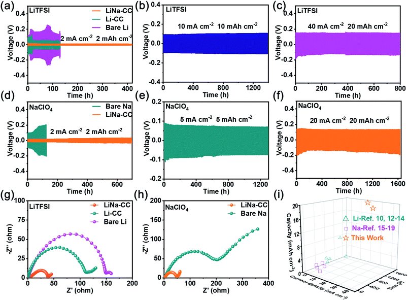
Symmetric cells assembled with various metal electrodes (e.g., bare Li, bare Na, LiNa-CC and Li-CC) were tested at various current densities to further explore the superiority of the LiNa-CC electrode. As shown in Fig. 3d, the LiNa-CC electrode exhibits a high exchange current density of 12.4 and 4.0 mA cm−2 in NaClO4 and LiTFSI, respectively, at 0.1 V, which are much higher than the corresponding values for the bare Li, bare Na and the LiNa-alloy (Fig. S6c, ESI†) electrodes. Fig. 4a shows that the voltage hysteresis for the battery based on the bare Li electrodes increased initially and rapidly reached ∼0.4 V due to the unprotected Li and the poor charge transfer kinetics. For the Li-CC electrode, a lower voltage hysteresis of ∼224 mV and more stable cycling stability are observed (Fig. 4a) due to the protection/support by the conductive carbon matrix.37 More importantly, the LiNa-CC electrode exhibited an excellent cycling stability with the lowest voltage hysteresis of ∼29 mV. However, the LiNa-alloy electrode delivered higher voltage hysteresis (∼117 mV, Fig. S6a, ESI†) than LiNa-CC, further demonstrating the advantages of the LiNa-CC electrode. Even when cycled at ultrahigh current densities of 10 mA cm−2 (Fig. 4b) and 40 mA cm−2 (Fig. 4c), the LiNa-CC electrode can still run for more than 1400 and 800 h with a low voltage hysteresis of ∼191 and ∼290 mV, respectively, and without any obvious voltage fluctuations. The electrochemical performance for the Na plating/stripping was also evaluated. As shown in Fig. 4d and f, the LiNa-CC symmetric cell reveals a stable voltage hysteresis of ∼56 mV for more than 700 h tested in the Na ion electrolyte at a current density of 2 mA cm−2 (2 mA h cm−2). Even at much higher current densities of 5 mA cm−2 and 20 mA cm−2, the LiNa-CC symmetric cell can still run for more than 1300 and 1650 h, respectively, with a stable voltage hysteresis (Fig. 4e and f). However, its counterpart based on the bare Na (Fig. 4d) and LiNa-alloy (Fig. S6b, ESI†) electrode exhibits a much larger polarization voltage and short cycling life.The EIS data for various symmetric cells were measured in the Li and Na ion electrolytes. As shown in Fig. 4g, the symmetric cell using the bare Li electrode in LiTFSI exhibits the largest charge transfer resistance of about 150 Ω, among the LiNa-CC (38 Ω), LiNa-alloy (67 Ω, Fig. S6d, ESI†) and Li-CC (112 Ω) electrodes, due to the poor charge transfer kinetics and the large passivation.33 A comparison with Fig. S5 and Table S2 (ESI†) shows that the impedance of the bare Li, Li-CC and LiNa-CC symmetric batteries drops to 13, 5 and 3 Ω, respectively, after 5 cycles, due to the increased electrochemical surface area of the electrodes induced by electrochemical activation.40 Compared to the bare Na (Fig. 4h) and LiNa-alloy (Fig. S6d, ESI†) electrodes, the LiNa-CC electrode also has the lowest charge transfer resistance in the Na ion electrolyte, showing the great potential of the LiNa-CC electrode. In fact, the LiNa-CC symmetric cell has shown even superior cell performance to some recently reported alkali metal symmetric cells (Fig. 4i and Table S3, ESI†).
To explore the possible impact of the Li/Na content on the Li/Na plating/stripping, symmetric batteries using LiNa-CC electrodes with various Li/Na molar ratios were also examined in the Li and Na ion electrolyte. As shown in Fig. S7a (ESI†), after the introduction of Na, the LiNa-CC-6 electrode exhibited better Li plating/stripping performance than Li-CC, with a stable voltage hysteresis around 110 mV for more than 500 h, further suggesting the superiority of the Li–Na alloy strategy. However, with further increase of the Na content, LiNa-CC-0.5 reveals poorer stability with larger voltage hysteresis and less cycle time. For Na plating/stripping, the galvanostatic charge/discharge curves (Fig. S8a, ESI†) show that the voltage hysteresis of LiNa-CC-6 rapidly increases to ∼338 mV after only 54 h, indicating that the high content of Li aggravated the polarization during the Na plating/stripping process. Then, LiNa-CC-1 shows a voltage hysteresis of about ∼136 mV after 500 h. However, LiNa-CC-0.5 exhibits a larger voltage hysteresis (∼176.1 mV) with a distinct fluctuation, indicating that the small amount of Li cannot effectively prevent the polarization and the growth of Na dendrites,53 which was further confirmed by the EIS results (Fig. S8b, ESI†).
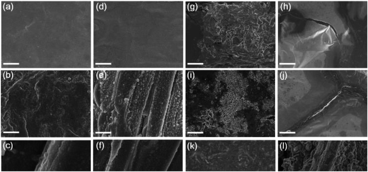
To further study the effects of the LiNa-CC electrode on suppression of the dendrite growth and the crack formation, we investigated the deposition behaviours of various electrodes (bare Li, bare Na, Li-CC and LiNa-CC) in the Li and Na ion electrolytes, respectively. These metal electrodes were investigated by SEM before and after cycling at a current density of 0.5 mA cm−2 (0.5 mA h cm−2), as shown in Fig. 5. In the Li ion electrolyte, the bare Li electrode shows a protuberant and cracked surface (Fig. 5g and h). In contrast, the Li-CC electrode exhibits no obvious crack and fewer protuberances (Fig. 5k and l), indicating that the carbon matrix has partly depressed the growth of the dendrites and repaired the cracks.23,40 However, the LiNa-CC electrode shows an apparently smooth surface without obvious cracks and dendrites (Fig. 5a–c), demonstrating effective suppression of the dendrite growth and crack formation. Moreover, in the Na electrolyte, no distinct dendrite and crack could be found on the surface of the LiNa-CC electrode after cycling (Fig. 5d–f). In addition, the XRD patterns (Fig. S9, ESI†) and the cross sectional SEM images (Fig. S10, ESI†) of the LiNa-CC electrode in different discharge/charge states further confirmed the high reversibility and stability of the LiNa-CC electrode. Such good electrochemical behaviours of the LiNa-CC electrode could be because the Li–Na alloy coated carbon fibres in the carbon cloth promoted the formation of a LiNa shell, leading to uniform nucleation, restrained volume expansion and suppressed dendrite formation.28,31,39 In contrast, the surface of the bare Na electrode remained rough and cracked (Fig. 5i and j).
The possible mechanism for the suppression of the dendrite growth and crack formation by the LiNa-CC electrode is illustrated in Fig. 1d and e, due to the electrochemical activation in Li or Na ion electrolyte (Fig. 1e). For Li plating/stripping in Li ion electrolyte, Li is dominant during the electrochemical process, and the carbon matrix would reduce the severe polarization and local current density to relieve the formation of Li dendrites and cracks.19,55 In the Na ion electrolyte, however, Na acts as the dominant species in the LiNa-CC electrode. Owing to the greater electrostatic shielding effect of Li+,56 the formation of Na dendrites can be effectively suppressed.54 Notably, a low content of Li cannot significantly enhance the Na deposition process and a large amount of Li would aggravate the polarization of Na.53 Furthermore, the thin layer of the Li and Na mixture on the LiNa-CC anode (Fig. 1e) could act as an artificial solid electrolyte interface (SEI) to protect the LiNa alloy from dissociation into the electrolyte solution in batteries, leading to high stability.
To verify the as-proposed mechanism and better understand the plating/stripping of Li and Na on the LiNa-CC electrode with various Li/Na molar ratios, we performed density functional theory (DFT) simulations, using the Materials Studio 6.0 package, to work out the adsorption energy between Li/Na atoms and various metal electrodes. For Li plating/stripping, the adsorption energy of Li atoms on the Li-CC electrode was estimated to be −0.46 eV (Fig. S11a, ESI†). Thereafter, the adsorption energy exhibits a rapid decrease after the introduction of Na, and reaches −2.53 eV for a Li/Na molar ratio of 2![[thin space (1/6-em)]](https://www.rsc.org/images/entities/char_2009.gif) :
:![[thin space (1/6-em)]](https://www.rsc.org/images/entities/char_2009.gif) 1. Then, the adsorption energy increased to 1.45 eV with the further increase of the Na content to a Li/Na molar ratio of 1
1. Then, the adsorption energy increased to 1.45 eV with the further increase of the Na content to a Li/Na molar ratio of 1![[thin space (1/6-em)]](https://www.rsc.org/images/entities/char_2009.gif) :
:![[thin space (1/6-em)]](https://www.rsc.org/images/entities/char_2009.gif) 6. The Na plating/stripping shows a similar result to that of Li and LiNa-CC electrodes with a Li/Na molar ratio of 2
6. The Na plating/stripping shows a similar result to that of Li and LiNa-CC electrodes with a Li/Na molar ratio of 2![[thin space (1/6-em)]](https://www.rsc.org/images/entities/char_2009.gif) :
:![[thin space (1/6-em)]](https://www.rsc.org/images/entities/char_2009.gif) 1 and the lowest adsorption energy of −1.98 eV (Fig. S11b, ESI†). Such theoretical results are consistent with the experimental performances, demonstrating the superiority of the LiNa-CC electrode with the optimized Li/Na ratio.
1 and the lowest adsorption energy of −1.98 eV (Fig. S11b, ESI†). Such theoretical results are consistent with the experimental performances, demonstrating the superiority of the LiNa-CC electrode with the optimized Li/Na ratio.
Electrochemical performance of the LiNa-CC electrode in metal–iodine batteries
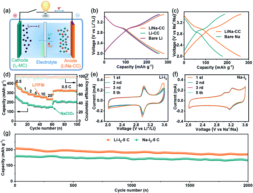
In view of the aforementioned electrochemical performance of the LiNa-CC metal electrode (e.g., the fast charge transfer kinetics, excellent stability and good reversibility), we constructed metal–iodine (LiNa-CC//I2) batteries using the LiTFSI and NaClO4 based electrolytes and iodine–carbon composites as the cathode, which were based on the Li/Na plating/stripping for the anode and the redox reaction of iodine in the cathode (Fig. 6a).Fig. 6b and S15a (ESI†) reproduce the galvanostatic discharge/charge profiles of the LiNa-CC//I2, Li-CC//I2, bare Li//I2 and Li–Na alloy//I2 batteries in the Li ion electrolyte at a current density of 2C (1C = 211 mA g−1), which show almost identical charge–discharge curves with a distinct voltage plateau over 3.0–3.1 V associated with the I3−/I− redox couple. The corresponding discharge/charge curves with a voltage plateau over 3.0 V for the LiNa-CC electrode in Na–I2 batteries using 1 M NaClO4/DME/DOL as the electrolyte (Fig. 6c) and the CV curves shown in Fig. 6e and f further demonstrate the redox reaction of the I3−/I− couple.48,49 Notably, the LiNa-CC and Li–Na alloy electrodes (Fig. S15a, ESI†) both deliver a high discharge voltage plateau compared to bare Na, which could be ascribed to the contribution of the Li ions, and we will see later. As shown in Fig. 6d, the LiNa-CC electrode in LiTFSI exhibits a reversible discharge capacity of 364.1, 310.9, 285.5, 266.2 and 256.3 mA h g−1 at a current density of 0.5, 1, 2, 5 and 10C, respectively. Even at an extremely high rate of 20C, LiNa-CC can still maintain a reversible capacity of 236.2 mA h g−1 with a retention of 64.8% initial capacity. Furthermore, the reversible capacity returned to 322.6 mA h g−1 upon reducing the rate back to 0.5C, indicating the good rate capability for the LiNa-CC anode in the Li–I2 battery. Such high discharge capacities are even higher than the theoretical value (211 mA h g−1) for the Li–I2 battery. This is because the pure MC matrix could also contribute to the whole capacity owing to capacitive contribution (37.2 mA h g−1) as shown in Fig. S12 (ESI†).
A similar rate capability was observed for the same LiNa-CC anode in NaClO4 (Fig. 6d). However, it should be noted that the discharge capacity of LiNa-CC in the Na ion electrolyte (Fig. 6c, e, S15a and b, ESI†) is smaller than that in the Li ion electrolyte (Fig. 6b, e, S15a and b, ESI†), which is most probably due to the relatively slow diffusion kinetics for the Na ion associated with its relatively large size.48 However, the Li–Na alloy (Fig. S15b, ESI†), Li-CC and bare Li (Fig. S14d, ESI†) as well as the bare Na anode (Fig. S14e, ESI†) all revealed inferior rate capability. Fig. S13 and S15c (ESI†) show the long cycling performance for various metal–iodine batteries developed in this study. As can be seen, the reversible capacity for the bare Li and Li-CC (Fig. S13a, ESI†) based batteries continuously decreases with increasing cycles at a current density of 2C. However, their LiNa-CC counterpart delivered a stable reversible capacity of 242.7 mA h g−1 with a capacity retention of 94.6% up to 400 cycles. Similar cycling performances were also observed for Na–I2 batteries with the bare Na or LiNa-CC anode (Fig. S13b, ESI†) indicating that the LiNa-CC electrode has the better stability (a capacity retention of 91.2% after 400 cycles) at 0.5C. In sharp contrast, the bare Na anode shows a very low capacity retention of 76.8% only after 100 cycles. In addition, as shown in Fig. S15d (ESI†), the Li–Na alloy anode reveals inferior cycling stability to LiNa-CC but better than that of bare Li and bare Na anodes, suggesting the superiority of the alloy strategy as well as the carbon cloth.
Furthermore, as shown in Fig. 6g, the LiNa-CC//I2 battery could display a reversible capacity of about 175.4 and 133.3 mA h g−1 and capacity retention of 84.8% and 83.3% after 2000 cycles at a current density of 5 C for Li–I2 and Na–I2 batteries, respectively, indicating a good long-term cycling stability (Table S5, ESI†) and fast kinetics (Fig. S14, S15c and Table S4, ESI†) for the LiNa-CC electrode. These results have demonstrated that the newly developed LiNa-CC electrode can effectively work as a bifunctional electrode for high-performance metal–iodine (Li–I2 and Na–I2) batteries.
To further demonstrate the reversibility of these metal–iodine batteries, we performed XRD, XPS and SEM studies to analyse the discharge products. The SEM images given in Fig. S16 (ESI†) show a similar morphology for the cathode before and after discharge in Li and Na ion electrolyte, indicating the uniform distribution of the discharge products (LiI and NaI) in the carbon matrix. The XPS spectra in Fig. S17 (ESI†) reveal that the Li and Na signals are both detected in the Li and Na ion electrolyte, indicating the occurrence of Li–I2 and Na–I2 battery reactions in alloy–iodine batteries. The XRD patterns in Fig. S18 (ESI†) also confirm the existence of the LiI and NaI in the iodine–carbon cathode after discharge in the Li or Na electrolyte, consistent with the SEM and the XPS results, demonstrating that this novel LiNa-CC anode can serve for both high-performance Li–I2 and Na–I2 batteries.
Conclusions
In summary, we have developed a bifunctional and ultra-stable alkali metal anode by coating a molten Li–Na alloy on a 3D carbon cloth to prepare a dendrite-free and crack-eliminated LiNa-CC anode with an optimized content of Li/Na and the morphological and chemical structures. The synergistic effects between the conductive carbon matrix and the Li–Na alloy coating in the composite anode lead to an enhanced conductivity and electrolyte transport kinetics. The newly developed LiNa-CC anode exhibited a high reversibility and good stability in both symmetric cells and metal–iodine batteries. This novel approach may provide a strategy to develop multifunctional and stable alkali metal anodes for next generation energy storage systems.Conflicts of interest
The authors declare no competing financial interest.Acknowledgements
This work was partly supported by the National Key Research and Development Program of China (2017YFA0206500), the Key Program of the National Natural Science Foundation of China (51732002), the National Natural Science Foundation of China (21905017), Distinguished Scientist Program at BUCT (buctylkxj02), the Start-Up Fund for Talent Introduction of Beijing University of Chemical Technology (buctrc202007), and the Australian Research Council (ARC, DP 190103881 and FL 190100126).References
- J. Liu, Z. Bao, Y. Cui, E. J. Dufek, J. B. Goodenough, P. Khalifah, Q. Li, B. Y. Liaw, P. Liu, A. Manthiram, Y. S. Meng, V. R. Subramanian, M. F. Toney, V. V. Viswanathan, M. S. Whittingham, J. Xiao, W. Xu, J. Yang, X. Q. Yang and J. G. Zhang, Nat. Energy, 2019, 4, 180–186 CrossRef CAS.
- T. Kim, W. Song, D.-Y. Son, L. K. Ono and Y. Qi, J. Mater. Chem. A, 2019, 7, 2942–2964 RSC.
- M. Li, J. Lu, Z. Chen and K. Amine, Adv. Mater., 2018, 30, 1800561 CrossRef PubMed.
- T. Li, D. Yu, J. Liu and F. Wang, ACS Appl. Mater. Interfaces, 2019, 11, 37559–37566 CrossRef CAS PubMed.
- Q. Zhao, Y. Lu, Z. Zhu, Z. Tao and J. Chen, Nano Lett., 2015, 15, 5982–5987 CrossRef CAS PubMed.
- M. D. Tikekar, S. Choudhury, Z. Tu and L. A. Archer, Nat. Energy, 2016, 1, 1–7 Search PubMed.
- Z. W. Seh, J. Sun, Y. Sun and Y. Cui, ACS Cent. Sci., 2015, 1, 449–455 CrossRef CAS.
- S. Liu, X. Xia, Y. Zhong, S. Deng, Z. Yao, L. Zhang, X. B. Cheng, X. Wang, Q. Zhang and J. Tu, Adv. Energy Mater., 2018, 8, 1702322 CrossRef.
- J. Luo, C. Wang, H. Wang, X. Hu, E. Matios, X. Lu, W. Zhang, X. Tao and W. Li, Adv. Funct. Mater., 2019, 29, 1805946 CrossRef.
- X. Wu, D. P. Leonard and X. Ji, Chem. Mater., 2017, 29, 5031–5042 CrossRef CAS.
- E. Cha, M. D. Patel, J. Park, J. Hwang, V. Prasad, K. Cho and W. Choi, Nat. Nanotechnol., 2018, 13, 337–344 CrossRef CAS.
- Y. Li, Y. Li, A. Pei, K. Yan, Y. Sun, C. L. Wu, L. M. Joubert, R. Chin, A. L. Koh, Y. Yu, J. Perrino, B. Butz, S. Chu and Y. Cui, Science, 2017, 358, 506–510 CrossRef CAS PubMed.
- X. Liang, Q. Pang, I. R. Kochetkov, M. S. Sempere, H. Huang, X. Sun and L. F. Nazar, Nat. Energy, 2017, 2, 17119 CrossRef CAS.
- N. Li, Y. Shi, Y. Yin, X. Zeng, J. Li, C. Li, L. Wan, R. Wen and Y. Guo, Angew. Chem., Int. Ed., 2018, 57, 1505–1509 CrossRef CAS PubMed.
- J. Xie, L. Liao, Y. Gong, Y. Li, F. Shi, A. Pei, J. Sun, R. Zhang, B. Kong, R. Subbaraman, J. Christensen and Y. Cui, Sci. Adv., 2017, 3, eaao3170 CrossRef PubMed.
- Z. Wen, Y. Peng, J. Cong, H. Hua, Y. Lin, J. Xiong, J. Zeng and J. Zhao, Nano Res., 2019, 12, 2535–2542 CrossRef CAS.
- X. Ge, S. Liu, M. Qiao, Y. Chen, Y. Li, J. Bao and X. Zhou, Angew. Chem., Int. Ed., 2019, 58, 14578–14583 CrossRef CAS PubMed.
- W. Luo, C. F. Lin, O. Zhao, M. Noked, Y. Zhang, G. W. Rubloff and L. Hu, Adv. Energy Mater., 2017, 7, 1601526 CrossRef.
- L. Xue, H. Gao, Y. Li and J. B. Goodenough, J. Am. Chem. Soc., 2018, 140, 3292–3298 CrossRef CAS PubMed.
- L. Liu, Y. X. Yin, J. Y. Li, S. H. Wang, Y. G. Guo and L. J. Wan, Adv. Mater., 2018, 30, 1706216 CrossRef PubMed.
- D. Lin, Y. Liu, Z. Liang, H. W. Lee, J. Sun, H. Wang, K. Yan, J. Xie and Y. Cui, Nat. Nanotechnol., 2016, 11, 626–632 CrossRef CAS PubMed.
- C. Chu, N. Wang, L. Li, L. Lin, F. Tian, Y. Li, J. Yang, S. Dou and Y. Qian, Energy Storage Mater., 2019, 23, 137–143 CrossRef.
- M. Zhang, H. Wang, S. Zhang and C. Deng, J. Mater. Chem. A, 2018, 6, 9019–9031 RSC.
- W. Luo, Y. Zhang, S. Xu, J. Dai, E. Hitz, Y. Li, C. Yang, C. Chen, B. Liu and L. Hu, Nano Lett., 2017, 17, 3792–3797 CrossRef CAS PubMed.
- Y. Zhang, C. Wang, G. Pastel, Y. Kuang, H. Xie, Y. Li, B. Liu, W. Luo, C. Chen and L. Hu, Adv. Energy Mater., 2018, 8, 1800635 CrossRef.
- H. Gan, J. Wu, H. Chen, R. Li and H. Liu, J. Mater. Chem. A, 2020, 8, 13480–13489 RSC.
- H. Wang, M. Liu, X. Wang, W. Zhang, Y. Che, L. Chen, Y. Wu and W. Li, J. Mater. Chem. A, 2020, 8, 12045–12054 RSC.
- F. Ye, X. Zhang, K. Liao, Q. Lu, X. Zou, R. Ran, W. Zhou, Y. Zhong and Z. Shao, J. Mater. Chem. A, 2020, 8, 9733–9742 RSC.
- Q. Jin, X. Zhang, H. Gao, L. Li and Z. Zhang, J. Mater. Chem. A, 2020, 8, 8979–8988 RSC.
- G. Chen, Y. Bai, Y. Gao, F. Wu and C. Wu, Acta Phys.-Chim. Sin., 2020, 36, 1905009 Search PubMed.
- S. Chi, X. Qi, Y. Hu and L. Fan, Adv. Energy Mater., 2018, 8, 1702764 CrossRef.
- B. Sun, P. Li, J. Zhang, D. Wang, P. Munroe, C. Wang, P. H. L. Notten and G. Wang, Adv. Mater., 2018, 30, 1801334 CrossRef PubMed.
- L. Zhang, S. Peng, Y. Ding, X. Guo, Y. Qian, H. Celio, G. He and G. Yu, Energy Environ. Sci., 2019, 12, 1989–1998 RSC.
- J. Zhao, G. Zhou, K. Yan, J. Xie, Y. Li, L. Liao, Y. Jin, K. Liu, P.-C. Hsu, J. Wang, H. M. Cheng and Y. Cui, Nat. Nanotechnol., 2017, 12, 993–999 CrossRef CAS PubMed.
- C. Luo, M. Gao, Z. Sun, X. Zhang, Z. Tang and X. Zhou, Corros. Eng., Sci. Technol., 2015, 50, 390–396 CrossRef CAS.
- Q. Zhang, J. Mao, W. K. Pang, T. Zheng, V. Sencadas, Y. Chen, Y. Liu and Z. Guo, Adv. Energy Mater., 2018, 8, 1703288 CrossRef.
- Y. Zhu, J. Cao, H. Chen, Q. Yu and B. Li, J. Mater. Chem. A, 2019, 7, 6832–6839 RSC.
- K.-H. Chen, K. N. Wood, E. Kazyak, W. S. LePage, A. L. Davis, A. J. Sanchez and N. P. Dasgupta, J. Mater. Chem. A, 2017, 5, 11671–11681 RSC.
- G. He, Q. Li, Y. Shen and Y. Ding, Angew. Chem., Int. Ed., 2019, 58, 1–6 CrossRef.
- K. Li, Z. Hu, J. Ma, S. Chen, D. Mu and J. Zhang, Adv. Mater., 2019, 31, 1902399 CrossRef PubMed.
- H. Zhong, Y. Wu, F. Ding, L. Sang and Y. Mai, Electrochim. Acta, 2019, 304, 255–262 CrossRef CAS.
- H. Kim, J. T. Lee, D. C. Lee, M. Oschatz, W. I. Cho, S. Kaskel and G. Yushin, Electrochem. Commun., 2013, 36, 38–41 CrossRef CAS.
- J. Ma, F. Meng, Y. Yu, D. Liu, J. Yan, Y. Zhang, X. Zhang and Q. Jiang, Nat. Chem., 2019, 11, 64–70 CrossRef CAS PubMed.
- J. H. Um, K. Kim, J. Park, Y.-E. Sung and S.-H. Yu, J. Mater. Chem. A, 2020, 8, 13874–13895 RSC.
- C. Xiong, Z. Wang, X. Peng, Y. Guo, S. Xu and T. Zhao, J. Mater. Chem. A, 2020, 8, 14114–14125 RSC.
- G. Wang, X. Zhu, A. Rashid, Z. Hu, P. Sun, Q. Zhang and L. Zhang, J. Mater. Chem. A, 2020, 8, 13351–13363 RSC.
- H. Tian, T. Gao, X. Li, X. Wang, C. Luo, X. Fan, C. Yang, L. Suo, Z. Ma, W. Han and C. Wang, Nat. Commun., 2017, 8, 14083 CrossRef CAS PubMed.
- D. Gong, B. Wang, J. Zhu, R. Podila, A. M. Rao, X. Yu, Z. Xu and B. Lu, Adv. Energy Mater., 2017, 7, 1601885 CrossRef.
- K. Lu, Z. Hu, J. Ma, H. Ma, L. Dai and J. Zhang, Nat. Commun., 2017, 8, 527 CrossRef PubMed.
- N. Xiao, J. Zheng, G. Gourdin, L. Schkeryantz and Y. Wu, ACS Appl. Mater. Interfaces, 2019, 11, 16571–16577 CrossRef CAS PubMed.
- S. Wei, Z. Cheng, P. Nath, M. D. Tikekar, G. Li and L. A. Archer, Sci. Adv., 2018, 4, eaao6243 CrossRef PubMed.
- W. Zhang, Y. Huang, Y. Liu, L. Wang, S. Chou and H. Liu, Adv. Energy Mater., 2019, 9, 1900464 CrossRef.
- J. Xu, M. Wang, N. P. Wickramaratne, M. Jaroniec, S. Dou and L. Dai, Adv. Mater., 2015, 27, 2042–2048 CrossRef CAS PubMed.
- Q. Zhang, Y. Lu, L. Miao, Q. Zhao, K. Xia, J. Liang, S. L. Chou and J. Chen, Angew. Chem., Int. Ed., 2018, 57, 14796–14800 CrossRef CAS PubMed.
- K. P. Doyle, C. M. Lang, K. Kim and P. A. Kohl, J. Electrochem. Soc., 2006, 153, A1353–A1357 CrossRef CAS.
- W. Li, H. Yao, K. Yan, G. Zheng, Z. Liang, Y. Chiang and Y. Cui, Nat. Commun., 2015, 6, 7436 CrossRef CAS PubMed.
Footnote |
| † Electronic supplementary information (ESI) available: Experimental details, Fig. S1–S18 and Tables S1–S5. See DOI: 10.1039/d0ta08072a |
| This journal is © The Royal Society of Chemistry 2021 |

