
 Open Access Article
 This Open Access Article is licensed under a Creative Commons Attribution-Non Commercial 3.0 Unported Licence
Effective 3D open-channel nanostructures of a MgMn2O4 positive electrode for rechargeable Mg batteries operated at room temperature†
Kazuki
Sone
a,
Yoshihiro
Hayashi
 a,
Toshihiko
Mandai
b,
Shunsuke
Yagi
c,
Yuya
Oaki
a and
Hiroaki
Imai
*a
a,
Toshihiko
Mandai
b,
Shunsuke
Yagi
c,
Yuya
Oaki
a and
Hiroaki
Imai
*a
aDepartment of Applied Chemistry, Faculty of Science and Technology, Keio University, 3-14-1 Hiyoshi, Kohoku-ku, Yokohama 223-8522, Japan. E-mail: hiroaki@applc.keio.ac.jp
bCenter for Research on Energy and Environmental Materials, National Institute for Materials Science (NIMS), 1-1 Namiki, Tsukuba, 305-0044 Ibaraki, Japan
cInstitute of Industrial Science, The University of Tokyo, 4-6-1 Komaba, Meguro-ku, Tokyo 153-8505, Japan
First published on 2nd March 2021
Abstract
Room-temperature operations of rechargeable Mg coin-cell batteries have been achieved using a Mg alloy negative electrode and a spinel MgMn2O4 (MMO)-positive electrode. The present work focuses on clarifying the effects of the physiochemical properties of the MMO powder including the specific surface area (SBET) and porosity of the positive electrode on Mg battery performances in practical applications. Finally, optimal specific surface area and porosity parameters were obtained that ensured excellent battery performances as a standard coin-cell at room temperature. A typical MMO powder synthesized using a modified sol–gel method with propylene oxide-driven complex polymerization had a large SBET > 200 m2 g−1, and more than 90% porosity with a triple-tiered 3D open-channel network. Here we evaluated the discharge capacity and the cyclability for room-temperature operation as a function of SBET in a full cell with a Mg negative electrode as well as half cells with a carbon graphite electrode. Irrespective of whether half cells or a full cell was used, the initial discharge capacity was found to depend linearly on the SBET of the porous MMO powder in a Mg tetrakis(hexafluoroisopropyl)borate/triglyme electrolyte with a wide potential window, ΔE > 3.6 V. Eventually, the maximum discharge capacity of 220 mA h g−1 was realized at 25 °C in the full cell using the 3D open-channel nanostructure with SBET = 236 m2 g−1. The cyclability in the full cell with the Mg alloy negative electrode, however, degraded with the increasing SBET, while no cyclability degradation was observed in the half cell with the carbon electrode. A possible mechanism is discussed regarding passivation of the Mg alloy electrode in discharge/charge cycles.
1. Introduction
For oncoming Internet of Things (IoT)-centric societies with portable augmented reality, self-driven cars, a smart environment, e-healthcare, etc.,1,2 a flexible electrical energy storage system with highly efficient rechargeable batteries is a key fundamental infrastructure based on interactive mobile systems with artificial intelligence (AI) technologies.3 Currently, rechargeable lithium-ion batteries (LIBs) exhibit excellent energy density, cycle stability, and a high discharging/charging rate. They could eventually become the most advanced electrochemical energy storage and conversion devices.4,5 In the current LIBs, however, a Li metal anode cannot be used due to dendrite formation accompanying the discharge/charge cycle, and graphite has been used as an alternative anode.6 Therefore, the theoretically high energy density could not be utilized fully.There has been increasing interest in the development of technologies for multivalent metal batteries, such as those using Mg, Ca, and Al, which have a higher volumetric energy density than Li.7,8 Among them, rechargeable Mg batteries (RMBs) have received particular attention.9 This is because the metal Mg negative electrode does not deposit dendrites due to the uniform precipitation and dissolution of Mg during the discharge/charge cycle. Although Mg is inferior to Li in terms of theoretical weight capacity and reduction potentials, its theoretical volume capacity is large as 3833 mA h cm−3, compared to the∼800 mA h cm−3 of graphite and 2046 mA h cm−3 of Li, making it the best for compactization. The redox potential (−2.37 V vs. Mg/Mg2+) theoretically allows relatively high battery voltages.
The practical application of RMBs, however, has a lot of issues with regard to the positive (cathode) electrode as well as the Mg negative (anode) electrodes and the electrolyte, in which the active Mg surface is easily covered with the resistive solid electrolyte interphase (SEI) at a high potential which fades the ability of Mg-ion plating/stripping.10,11 The other fundamental issue with cathode materials is the slow diffusion of Mg2+ in the solid, because the divalent ion strongly interacts with anions in the crystal lattice.12 Among the candidates for cathode materials, such as Chevrel-Mo6S8,13 spinel-Ti2S4,14 layered-V2O5 and MoO3,15 spinel multioxides with Mg2+ and multivalence transition metals are receiving attention, such as MgCo2O4 (MCO spinel) and MgMn2O4 (MMO spinel), which have higher voltages theoretically at +3.3 V and +2.9 V, respectively.16,17 Okamoto et al.18 found that the insertion of Mg2+ ions occurs in spinel oxides reversibly to transform the rock salt oxides at temperatures over 100 °C to enhance the Mg diffusion. Some direct observations have also been reported, such as Mg ion insertion into the spinel with phase transition to rock salt19,20 or the extraction to become Mg1−xMnO4.21
The easiest method to enhance the insertion/extraction of Mg ions is to heat the battery cells, but this is impractical for mobile consumer applications. The other method is to control the nanostructure of the positive electrode pasted with the spinel nanoparticles to ease the insertion/extraction of the Mg ions.22 We have designed an MMO powder with nanometer-scale particles in a double-tiered open-channel network, which improves Mg2+ diffusion from the electrolyte to the surface of the MMO nanoparticles.23 Here, electrochemical battery operations were investigated in a three-electrode beaker cell heated to 100 °C. However, the effects of the MMO powder characteristics, such as the specific surface area and porosity, on the room-temperature operation in a conventional coin cell remained unclear.
Because of the corrosive nature of typical chloride-containing electrolytes to the metal components of coin cells, there are very few reports evaluating coin-cell batteries with a Mg negative electrode and an MMO positive electrode.24 Therefore, halogen-free nonaqueous electrolytes,25–27 such as Mg bis(trifluoromethanesulfonyl)amide (Mg(TFSA)2)/tetraglyme (G4), have been developed to prevent corrosion of the metal components in the coin cells.28 Recently, a new class of noncorrosive electrolytes incorporating Mg tetrakis(hexafluoroisopropyl)borate (Mg[B(HFIP)4]2) was developed with a high anodic stability, over +3.5 V vs. Mg, and high oxidation resistance to promote the reversible stripping and plating of Mg on the negative electrode.29,30
In the present research, we adapted the Mg[B(HFIP)4]2/triglyme (G3)-based electrolyte to a two-electrode coin cell composed of a Mg alloy negative electrode and an MMO-positive electrode to evaluate the Mg battery operation at room temperature. First, we developed a modified sol–gel synthesis to prepare a variety of MMO powders with different specific surface areas (SBET), while preserving the 3D open-channel network inside. Then the electrical properties of the coin-cell batteries at 25 °C were investigated as a function of the SBET of the MMO powders to realize room-temperature operations of rechargeable Mg coin-cell batteries using a Mg negative electrode. Compared with the electrical properties of a half cell with a graphite negative electrode, some operational issues at room temperature are pointed out for the cyclable RMB in coin cells.
2. Experiment
2.1 Preparation of MMO powders for the positive electrode
All reagents were used as purchased without purification. We prepared MMO using a propylene-oxide-driven sol–gel method based on the procedure reported by Zhang et al.31 As illustrated in Fig. S1 in the ESI,† the MMO powders were prepared using a modified sol–gel method with propylene-oxide-driven complex polymerization: 6 mmol of MgCl2·6H2O (Fujifilm Wako Pure Chemical) and 12 mmol of MnCl2·4H2O (Fujifilm Wako Pure Chemical) were dissolved in 20 cm3 of water, and 18 mmol of citric acid (Fujifilm Wako Pure Chemical) and 12 mmol of propylene oxide (Kanto Chemical) as a polymerization agent were added to the solution. After this was stirred, the solution was irradiated with supersonic wave for 30 s, during which the sol–gel transformation occurred to form organometallic complex gels. Then the gels were kept in a water bath at 25 °C and aged for 1–168 h to develop an organic polymer network. The wet gels were then washed with ethanol and acetone three times to remove byproducts. Liquid in the pores of the aged gels was sequentially exchanged by immersing the gels in acetone and cyclohexane for 24 h. The replacement with cyclohexane was performed three times in three days. After exchanging the pore liquid, the gels were freeze-dried for 12 h, and the dried gels were calcined at 300–600 °C for 5 h in air to obtain the MMO powders. As a reference sample, an MMO powder was also synthesized using the inverse coprecipitation (IC) method,18,23 followed by calcination at 600 °C in air, which is referred to as an “MMO-IC” powder.Elemental analysis was performed using inductively coupled plasma atomic emission spectroscopy (ICP, Shimadzu ICPE-9000). Thermal decomposition of the dried gel of the organometallic complex to the MMO powder was monitored via thermogravimetry/differential thermal analysis (TG/DTA, Seiko TG/DTA6200). The dried-gel sample (2–5 mg) was placed on an alumina dish in air. The temperature range, the temperature rising rate, and the sampling interval were 30–1000 °C, 5 °C min−1, and 1 s, respectively. The particle size and the agglomeration state of the calcined MMO powders were observed using a scanning electron microscope (SEM, JEOL JSM-7100F) and a scanning transmission electron microscope (TEM, FEI Tecnai G2). The crystal phase of the calcined powder was analyzed via CuKα X-ray diffraction (XRD, Bruker D8 Advance Eco), in which the tube voltage and the current were 40 kV and 25 mA, respectively, at a sampling width of 0.04°, a scan speed of 10° min−1, and a diffraction angle of 2θ = 5–80°.
The specific surface area (SBET) of the MMO powder was determined using a nitrogen adsorption/desorption measuring device (Micromeritics 3Flex-3MP), where the pulverized sample was degassed in vacuo at 160 °C for 5 h and then measured at 77 K in liquid nitrogen to obtain the nitrogen adsorption isotherm. SBET was determined using the Brunauer–Emmett–Teller (BET) method, and the equivalent particle size (DBET) was calculated as DBET = 6/(SBET × ρ); ρ is an MMO density of 2.47 g cm−3. The pore-size distribution was determined using the Barrett–Joyner–Halenda (BJH) method. The distribution of the open-pore diameter and the cumulative-pore volume (Vpore) in the MMO powders were measured using a mercury intrusion porosimeter (MIP, Micromeritics Autopore IV 9500).
2.2 Assembling the coin-cell batteries
Fig. S2a in the ESI† shows the Mg coin-cell structure and the components inside, in which the stainless mechanical supporting plate, a negative electrode, and a separator disc made of a glass filter (Advantech GA55) immersed in an electrolyte were stacked on a positive electrode. The positive electrode was made as follows: the calcined MMO powder was mixed with acetylene black (AB, Denka Black, Denka) as an auxiliary agent for 10 min using a mortar and pestle, and then polytetrafluoroethylene (PTFE, Teflon fine powder, Du Pont-Mitsui Fluorochemicals) as a binder was mixed for another 10 min to prepare the electrode paste. The mixing ratio was MMO![[thin space (1/6-em)]](https://www.rsc.org/images/entities/char_2009.gif) :AB:PTFE = 6:3:1 in the weight ratio. About 2–3 mg of the electrode paste was spread on aluminum mesh of a current collector with a diameter of 8 mm and pressed at 4 MPa for 30 s, followed by heat treatment at 120 °C for 24 h in order to remove water adhering to the surface.
:AB:PTFE = 6:3:1 in the weight ratio. About 2–3 mg of the electrode paste was spread on aluminum mesh of a current collector with a diameter of 8 mm and pressed at 4 MPa for 30 s, followed by heat treatment at 120 °C for 24 h in order to remove water adhering to the surface.
The coin cells were made of the MMO positive electrode (∼0.5 cm2), a Mg alloy (AZ31 Mg:Al:Zn = 96:3:1 weight ratio, Nippon Kinzoku) negative electrode (∼0.69 cm2), and a separator immersed in the 0.3 mol dm−3 Mg[B(HFIP)4]2/G3 (Wako) electrolyte, referred to as “borate/G3” (Fig. S2b in the ESI†). Mg[B(HFIP)4]2 was synthesized according to the reported procedure.29 In order to prepare a standard coin cell, the thin negative electrode must be processed to fit in the small space of the coin-type vessel. Thus, we used a Mg alloy AZ31 containing Al and Zn as additives because Mg pure metal has less workability. In the present paper, the AZ31 negative electrode is tentatively referred to as the Mg negative electrode.
Galvanostatic discharge/charge measurements were performed using a battery-testing system (Hokuto Denko HJ1001SD8). The current density was 1/25C (1C = 260 mA g−1), and cutoff voltages of +0.2 and +4.0 V vs. Mg (AZ31)/Mg2+ were adopted. As references, two other half cells with a carbon graphite negative electrode were investigated with the Mg[B(HFIP)4]2/G3 electrolyte (Fig. S2c in the ESI†) or the 0.5 mol dm−3 Mg(ClO4)2/acetonitrile (AN) electrolyte, referred to as “perchlorate/AN” (Fig. S2d in the ESI†). The Mg alloy negative electrode was passivated through an electrochemical reaction with the electrolyte. Thus, we used an inert graphite as the counter electrode in the half cells to evaluate the stability of the positive electrode. The cutoff voltage was set between −2.0 V and +1.6 V vs. carbon for the former and between −1.0 V and +1.0 V vs. carbon for the latter according to cyclic voltammograms and current–voltage characteristics for the electrolytes (Fig. S3 and S4†). All of the measurements were performed at room temperature (25 °C).
3. Results and discussion
3.1 Precise control of the MMO powder characteristics
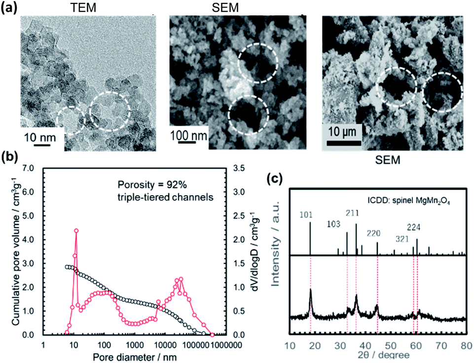 | ||
| Fig. 1 A typical example of the highly porous MMO powder: (a) TEM and SEM micrographs of the MMO powder after 5 h-calcination at 300 °C from the gel aged for 24 h with supersonic-aided quick gelation; (b) the diameter distribution of the open channels and the cumulative pore volume in the MMO powder measured using an MIP; and (c) the XRD pattern. | ||
The gel-aging time after the supersonic irradiation-aided sol–gel transformation also influenced the characteristics of the calcined MMO powder. Fig. 2 and 3 show the SEM/TEM micrographs and XRD patterns of the MMO powders calcined at 300 °C for 5 h from the gels aged for (a) 1 h, (b) 24 h, (c) 72 h, and (d) 168 h. SBET and DBET were obtained from the nitrogen adsorption/desorption isotherms (Fig. S5 in the ESI†). Based on ICP analysis, the composition of the calcined MMO powders was identical to the stoichiometry of Mg:Mn = 1:2. The particle size increased upon increasing the gel-aging time from 1 to 72 h (Fig. 2), and the shortest aging, 1 h, after the supersonic-irradiated gelation resulted in the MMO powder with SBET = 236 m2 g−1 and DBET = 10.3 nm. The XRD patterns for each MMO powder were broad (Fig. 3), but by prolonging the aging time from 1 to 72 h, some of the main peaks were found to be identical to 101, 211, and 220 in spinel. In the TEM micrographs, the inference fringe patterns were observed in the particles irrespective of the gel aging time, suggesting that the MMO particles preserve the spinel structure and are not fully amorphous. The peak broadening in the XRD patterns of the MMO powder prepared from the 168 h-aged gel is ascribed to the small size effect of crystalline particles.
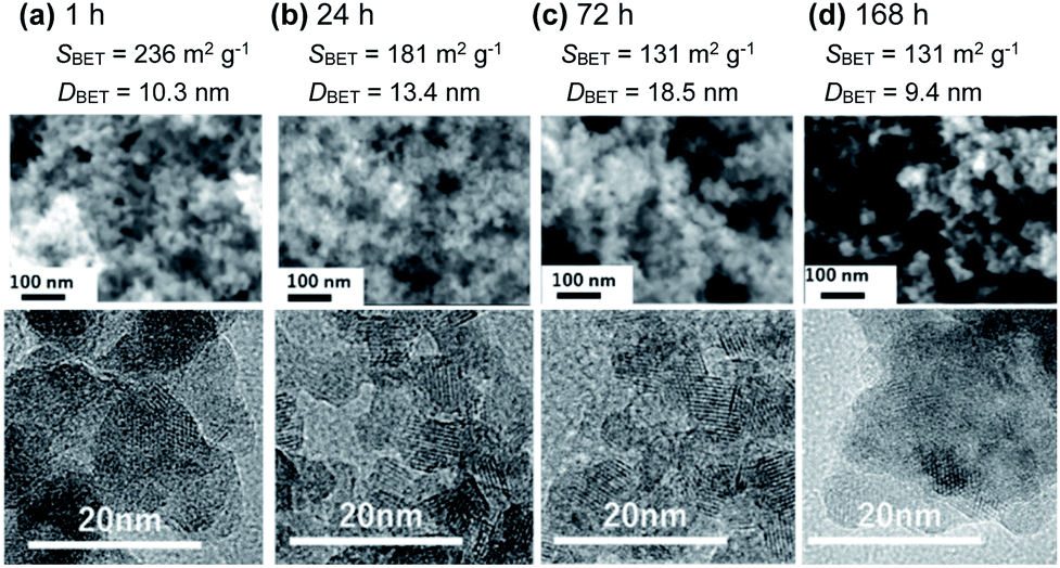 | ||
| Fig. 2 SEM (upper column) and TEM (lower column) micrographs of the MMO powders calcined at 300 °C from the gels aged for (a) 1 h, (b) 24 h, (c) 78 h, and (d) 168 h, with their SBET and DBET. | ||
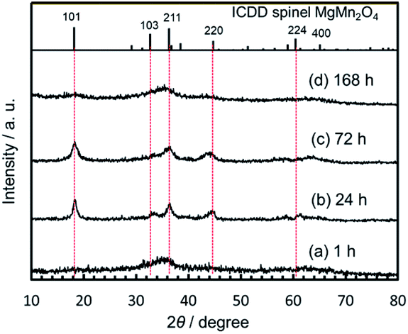 | ||
| Fig. 3 XRD patterns of the MMO powders obtained by calcination for 5 h at 300 °C from the gels aged for (a) 1 h, (b) 24 h, (c) 78 h, and (d) 168 h. The patterns of the MMO spinel and the diffraction indices are shown at the top. | ||
Interestingly, SBET was increased again to the largest value, 258 m2 g−1, by prolonging the aging time to 168 h. The XRD pattern becomes broad again due to the smallest particle size of DBET = 9.4 nm. Based on TG/DTA analysis (Fig. S6 in the ESI†), the dried gel aged for 168 h had the highest burnout temperature, around 358 °C, to remove the organic component, while the dried gels aged for less than 72 h were burned out at around 300–330 °C. When aging was prolonged for 168 h, the organometallic polymer was well developed, and particle growth was prevented in the inorganic MMO components during the calcination, keeping the MMO particles small.
Using an MIP, the distribution of the open-channel diameters and the cumulative specific volume were measured in the MMO powders calcined at 300 °C from the gels aged for different lengths of time (Fig. 1b and 4). It was found that the cumulative specific volume of the open pores was the largest with the shortest gel-aging time, and the MMO powder was estimated to have 97% porosity. The cumulative pore volume, or, essentially, the porosity, decreased with an increase in the gel-aging time, while the MMO powders from the gels aged for 1–24 h were preserved as the triple-tiered open-channel networks with pore diameters of approximately 20 nm, 0.5 μm, and 50 μm. With 72 h of aging, the smallest pores, 20 nm in diameter, disappeared, and the double-tiered open channels with diameters of approximately 100 nm and 0.5 μm were formed. With prolonged aging of 168 h, the MMO powder had a single-tiered open-channel network only with a diameter of approximately 50 μm. The smallest MMO particles, DBET = 9.4 nm, might be hardly agglomerated, with no interparticle space.
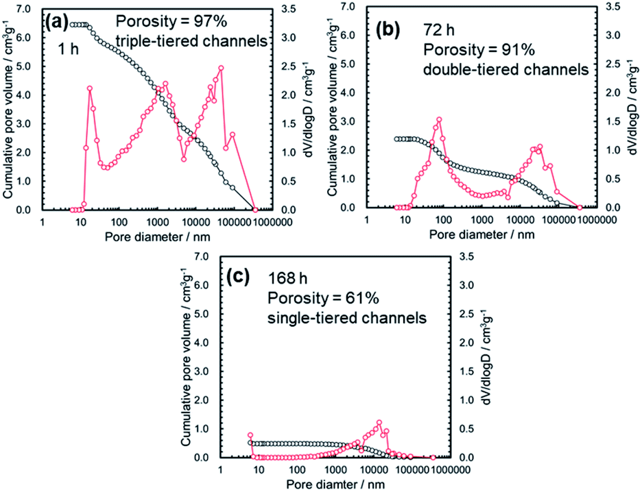 | ||
| Fig. 4 The diameter distribution of the open channels and the cumulative specific volume with their porosity measured using an MIP for the MMO powders calcined at 300 °C from the gels aged for (a) 1 h, (b) 72 h, and (c) 168 h. | ||
Fig. 5 summarizes the effects of the gel-aging times on the characteristics of the MMO powders calcined at 300 °C. When the gel-aging time was increased to 72 h, SBET decreased, while the porosity was preserved at over 90% with the triple- or double-tiered open-channel networks. The highly porous powder might be suitable for providing spaces to be uniformly mixed with the conductive AB and PTFE for the positive electrode.23 With a prolonged gel-aging time of up to 168 h, SBET increased again, but the porosity in the MMO powder was drastically decreased and hardly agglomerated. This would degrade the mixing uniformity of the MMO particles in the positive electrode, and the electrolyte might eventually be prevented from uniform supply to each of the MMO particles. The effect of the agglomeration on the discharge capacity is to be discussed in 3.2.3.1.
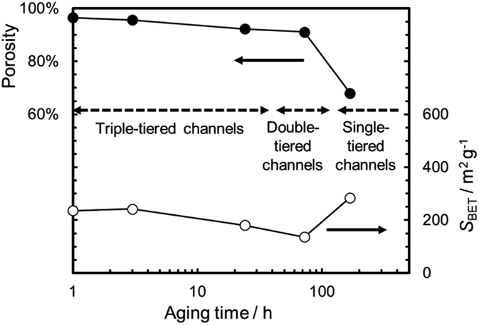 | ||
| Fig. 5 Porosity and SBET with schematic illustrations of the MMO powders calcined at 300 °C as a function of the gel-aging time. | ||
 | ||
| Fig. 6 SEM micrographs of the MMO powders obtained with 5 h calcination at (a) 300 °C, (b) 400 °C, (c) 500 °C, and (d) 600 °C. All of the gels were aged for 24 h. The MMO powder obtained by an inverse coprecipitation method (MMO-IC) is also shown (e). | ||
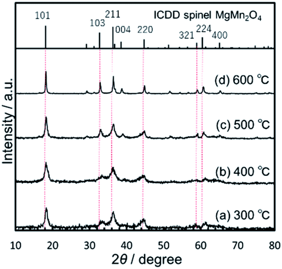 | ||
| Fig. 7 XRD patterns of the MMO powders obtained by 5 h calcination at (a) 300 °C, (b) 400 °C, (c) 500 °C, and (d) 600 °C. All of the gels were aged for 24 h. The patterns of the MMO spinel and the diffraction indices are shown at the top. | ||
Consequently, we have prepared seven types of MMO powders using the modified sol–gel method and an MMO-IC powder as a reference, with differences in SBET and porosity, for Mg coin-cell evaluation at room temperature.
3.2 Coin-cell batteries with the MMO positive electrode
By using a variety of sol–gel-derived MMO powders for the positive electrode, we have assembled three types of 2-electrode coin cells: (1) half cells with a carbon negative electrode and a Mg(ClO4)2/AN electrolyte: “C/(perchlorate/AN)/MMO”, (2) half cells with a carbon negative electrode and a Mg[B(HFIP)4]2/G3 electrolyte: “C/(borate/G3)/MMO”, and (3) a full cell with a Mg alloy negative electrode and a Mg[B(HFIP)4]2/G3 electrolyte: “Mg/(borate/G3)/MMO”. The half and full cells correspond to a Mg-ion coin cell and a rechargeable Mg coin cell, respectively, both of which used the MMO powders with different SBETs in the positive electrode. By comparing the full cell with the half cells, the effects of the Mg negative electrode on room-temperature operation will be clarified.Fig. 8a shows the room-temperature galvanostatic discharge/charge curves in the 1st cycle of the half cell, in which the MMO powders calcined at 300 °C from the gels aged for 1–168 h were used for the positive electrode. The discharge capacities at −1.0 V (vs. CE) were 65–80 mA h g−1, much larger than that with the agglomerated MMO-IC powder. In the charging process that followed, the potential increased to +1.0 V (vs. CE), and the charge capacities were almost equal to the discharge capacities, irrespective of the MMO powders.
 | ||
| Fig. 8 (a) Galvanostatic discharge/charge curves in the 1st cycle measured at 25 °C for the half cells with a carbon negative electrode and a Mg(ClO4)2/AN electrolyte. The MMO powders were calcined at 300 °C from the gels aged for 1 h, 3 h, 24 h, 72 h, and 168 h. The MMO-IC powder was used as a reference. (b) The discharge capacity at 25 °C in the 1st cycle of the half cell with a Mg(ClO4)2/AN electrolyte as a function of the SBET of the MMO powders in the positive electrode. | ||
Fig. 8b shows the discharge capacity in the 1st cycle as a function of the SBET of the MMO powders. The discharge capacity increased at SBET = 70 m2 g−1 but then was stagnant, irrespective of SBET. This is related to the narrow potential window of ΔE = 2.0 V, in which the electrochemical reaction of Mg ions at the interface between the electrolyte and the MMO particles is limited regardless of SBET. In other words, when the operation potential window is narrow for the Mg(ClO4)2/AN electrolyte, the effort to increase SBET is not effective in obtaining a higher discharge capacity.
Fig. 9a shows an example of the galvanostatic discharge/charge curves in the repeated cycles, in which the MMO powder calcined at 300 °C from the gel aged for 24 h was used. The discharge capacity at −1.0 V (vs. CE) was decreased slightly, but no abrupt degradation was observed in the 15 cycles. The cyclability was preserved irrespective of the MMO powders with a different SBET and DBET (Fig. 9b).
 | ||
| Fig. 9 (a) Galvanostatic curves in the cycles repeated at 25 °C for the half cell with a carbon negative electrode and a Mg(ClO4)2/AN electrolyte from the 1st to the 35th cycle. The positive electrode was mixed with the MMO powder calcined at 300 °C from the gel aged for 24 h. (b) The discharge capacity at 25 °C as a function of the cycles repeated for the half cell with a carbon negative electrode and a Mg(ClO4)2/AN electrolyte. In the positive electrode, the MMO powders were used from the 300 °C calcination of the gels aged for 1–168 h. | ||
In the half cell battery of C/(perchlorate/AN)/MMO with the modest ΔE = 2.0 V (−1.0 to +1.0 V vs. CE or +1.6 to +3.6 V vs. Mg/Mg2+), the discharge capacity is limited to around 70 mA h g−1 at 25 °C, irrespective of the SBET of the MMO powders, but is excellent in cyclability.
Fig. 10a shows typical galvanostatic curves in the cycles repeated at 25 °C for the half cell with a Mg[B(HFIP)4]2/G3 electrolyte with a wide potential window, ΔE = 3.6 V (−2.0 to +1.6 V vs. CE). Here, the MMO powder with SBET = 129 m2 g−1 was used. In the 1st cycle, the discharge capacity at −2.0 V (vs. CE) was 120 mA h g−1. On charging from −2.0 to +1.6 V (vs. CE), the charge capacity continuously increased and reached a value slightly over the discharge capacity. By the 5th cycle, the discharge capacities were preserved at 100–120 mA h g−1, and no drastic degradation was observed in the discharge capacities in the wide potential window. By the 10th cycle, the discharge curve was bent at around −1.7 V (vs. CE), probably due to some decomposition of the electrolyte.
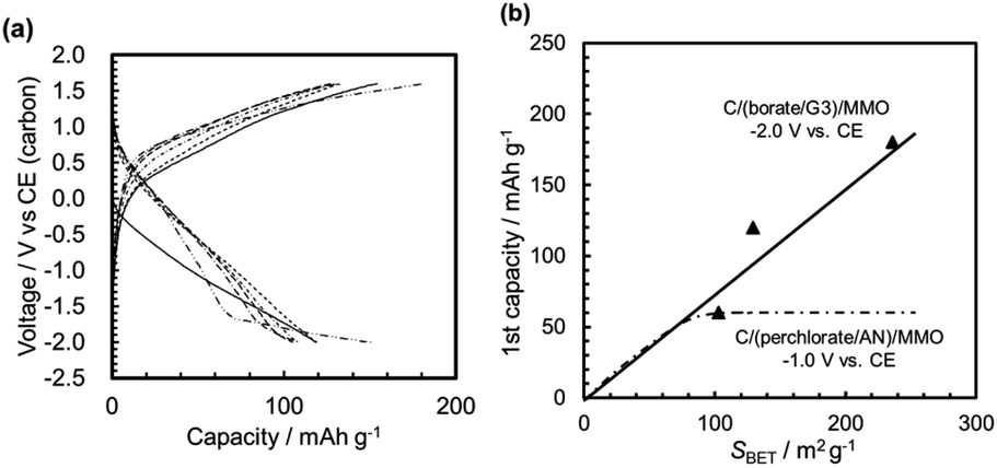 | ||
| Fig. 10 (a) Typical galvanostatic discharge/charge curves from the 1st to the 10th cycle at 25 °C for the half cells of C/(Borate/G3)/MMO, in which the MMO powders had been calcined at 400 °C from gels aged for 24 h. (b) The discharge capacity in the 1st first cycle as a function of the SBET of the MMO powders in half cells of C/(borate/G3)/MMO and C/(perchlorate/AN)/MMO. | ||
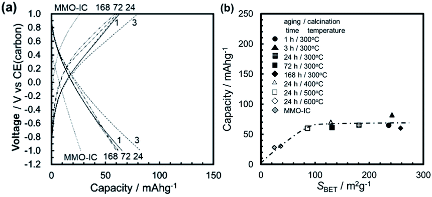
Fig. 10b shows the discharge capacity in the 1st cycle as a function of the SBET of the MMO powders in the half cell of C/(borate/G3)/MMO with ΔE = 3.6 V. Here, the 1st discharge capacity of the half cell of C/(perchlorate/AN)/MMO with ΔE = 2.0 V is also shown as a dashed-dotted line (see Fig. 8b). The discharge capacities were −2.0 V (vs. CE) and −1.0 V (vs. CE), respectively. It is clear that the discharge capacity increased linearly with the increasing SBET in the half cell of C/(borate/G3)/MMO. Eventually, a discharge capacity of 180 mA h g−1 was attained from the MMO powder with a maximum SBET = 236 m2 g−1. The Mg[B(HFIP)4]2/G3 electrolyte can deliver the full activity of the MMO powders with a large SBET due to the wide potential window, ΔE = 3.6 V.
This balanced performance in both the large discharge capacity and the cyclability in the wide potential window is attractive in spite of the half cell with the MMO positive electrode. Recently, Dong-Min Kim and co-workers33 found the co-intercalation of Mg2+ ions and diglyme into graphite with a double-layered structure in a magnesium-ion battery. We investigated our case with the Mg[B(HFIP)4]2/G3 electrolyte in our next step.
The low specific capacities during the 1st cycle are not ascribed to a high overpotential. The 1st scan for measuring the discharge capacity of the MMO powders started from +0.2 V and 0 V for C/(perchlorate/AN)/MMO and Mg/(borate/G3)/MMO, respectively. In the 2nd cycles and following, the MMO particles were charged by the charging scan of the 1st cycles. Therefore, the discharge scanning started from +1.0 and +1.6 V.
3.2.3.1 The initial discharge capacity. Fig. 11a shows the galvanostatic discharge/charge curves in the 1st cycle for the full cells with MMO powders calcined at 300 °C from gels aged for 1–168 h. Here, the MMO-IC with SBET = 23 m2 g−1 was also used as a reference. It was found that the discharge capacities at +0.2 V (vs. Mg/Mg2+) increased with a decrease in the gel-aging time, or, essentially, an increase in SBET, while the initial open circuit voltage (OCV) at 0 mA h g−1 for the bare MMO powders and the average discharge voltages were almost independent of SBET, such as +2.5 V (vs. Mg/Mg2+) and +1.2 V (vs. Mg/Mg2+), respectively (Fig. S9 in the ESI†).
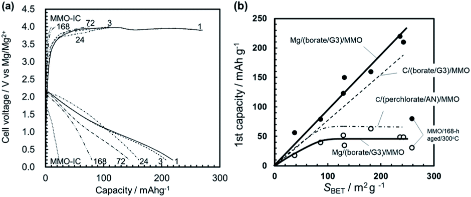 | ||
| Fig. 11 (a) Galvanostatic discharge/charge curves at 25 °C for the full cells, Mg/(borate/G3)/MMO. The MMO powder calcined at 300 °C from the gels aged for 1–168 h was used for the positive electrode. MMO-IC was also used as a reference. (b) The discharge capacity in the 1st cycle as a function of the SBET of the MMO powders in the Mg/(borate/G3)/MMO full cell. Plots marked with (●) and (○) show the discharge capacities at +0.2 V and +1.6 V (vs. Mg/Mg2+). The dashed line and the dashed-dotted line represent the 1st discharge capacitances for the half cells of C/(borate/G3)/MMO and C/(perchlorate/AN)/MMO, respectively. Here, the potential of 0 V in the half cells (vs. CE) is assumed to be equivalent to +2.6 V (vs. Mg/Mg2+). | ||
Fig. 11b shows the 1st discharge capacities as a function of SBET at discharge potentials of +0.2 V (vs. Mg/Mg2+) and +1.6 V (vs. Mg/Mg2+). The figure also indicates the 1st discharge capacities of the half cells of C/(borate/G3)/MMO and C/(perchlorate/AN)/MMO by a dashed line and a dashed-dotted line, respectively (see also Fig. 10b). Note that, in the case of C/(perchlorate/AN)/MMO, −1.0 V (vs. CE) is equivalent to +1.6 V (vs. Mg/Mg2+).23,34 The same assumption is applied to C/(borate/G3)/MMO. In the full cell, the 1st discharge capacity at a mild discharge potential of 1.6 V (vs. Mg/Mg2+) was stagnant at around 40 mA h g−1 over SBET = 80 m2 g−1, which is similar to that of the half cell of C/(perchlorate/AN)/MMO at the same discharge potential. At a low discharge potential such as 0.2 V (vs. Mg/Mg2+), on the other hand, the 1st discharge capacity linearly increased with SBET, similar to that of the half cell of C/(borate/G3)/MMO. Eventually, 220 mA h g−1 was obtained at room temperature from the Mg coin cell with porous MMO powders with a large SBET, 236 m2 g−1, in the positive electrode.
In addition, it is worth noting that not only SBET but also the porosity in the MMO powder is a very important factor in achieving a high discharge capacity; the MMO powder from the gel aged for 168 h had the largest SBET but the lowest porosity (see Fig. 5). The 1st discharge capacity at +0.2 V (vs. Mg/Mg2+) was the smallest and far below the trend line of the porous MMO powders. The low porosity with no three-dimensional open-channel network probably restricts the efficient supply of the viscous Mg[B(HFIP)4]2/G3 electrolyte to the MMO particles in the positive electrode. In other words, making an effort only to achieve a larger SBET or a smaller DBET is not sufficient to deliver the full activity of the MMO powders (see also Fig. S10 in the ESI†). It is essential to provide a sufficient space for carrying the Mg2+ cations to the MMO particles with a large SBET and releasing the [B(HFIP)4]− anions back to the solvent in the bulk at room temperature.
Namely, to achieve a large discharge capacity for room-temperature operation in the Mg coin cell, the best combination is to use porous MMO powder with a large SBET and a stable Mg[B(HFIP)4]2/G3 electrolyte in a wide potential window, such as ΔE = 3.8 V.
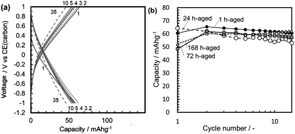
3.2.3.2 Cyclability. The Mg/(borate/G3)/MMO full cell, however, had some critical unsolved issues, such as cyclability. Fig. 12 shows the typical galvanostatic curves of Mg/(borate/G3)/MMO with different SBET areas, such as (a) 236 m2 g−1, (b) 131 m2 g−1, and (c) 37 m2 g−1, in which the discharge and charge were cycled in a wide potential window of +0.2 to +4.0 V (vs. Mg/Mg2+). In the case of SBET = 236 m2 g−1, the 1st discharge capacity was the largest, at 220 mA h g−1. However, in the charge step that followed, the charge potential was stagnant at around +3.7 V (vs. Mg/Mg2+) and then flattened at around +3.9 V (vs. Mg/Mg2+) with a charge capacity of ∼100 mA g−1. The charging potential did not reach the setting voltage of +4.0 V (vs. Mg/Mg2+), suggesting that the electrolyte was being decomposed during the charging step. In the 2nd cycle, the discharge capacity was drastically decreased, by 50%, to ∼110 mA h g−1. Through cycling, the cell potentials in the charging steps had been decreased, and the discharge capacities in the next discharging steps were dropping cycle by cycle (Fig. S11 in the ESI†). In the case of SBET = 131 m2 g−1, the severe degradation in cyclability was slightly moderated. The 1st discharge capacity was reduced to 145 mA h g−1 due to the reduced SBET. In the charge step that followed, however, the cell potential reached the setting voltage of +4.0 V (vs. Mg/Mg2+), resulting in a charge capacity of 96 mA h g−1, recovering 66% of the 1st discharge capacity. In the 2nd cycle, the discharge capacity dropped 45% to 80 mA h g−1. However, in the cycles that followed, the decrease in discharge capacity was suppressed to around 70 mA h g−1, while the charging potential reached +4.0 V (vs. Mg/Mg2+), except for the 10th step. In the case of SBET = 37 m2 g−1, the 1st discharge capacity was decreased to 60 mA h g−1; however, no abrupt decrease in the discharge capacity was observed, while the charging potential reached 4.0 V.
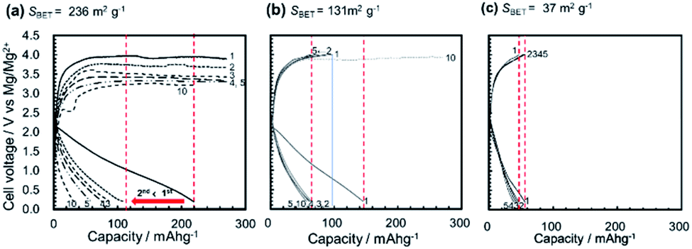 | ||
| Fig. 12 Galvanostatic curves of the discharge/charge cycles in Mg/(borate/G3)/MMO coin-cell batteries with MMO powders of (a) SBET = 236 m2 g−1 obtained by 5 h calcination at 300 °C from the gel aged for 1 h, (b) SBET = 131 m2 g−1 from the gel aged for 72 h, and (c) SBET = 37 m2 g−1 obtained by 5 h calcination at 600 °C from the gel aged for 24 h. The cycle conditions were +0.2 to +4.0 V vs. Mg/Mg2+ at 25 °C. | ||
Fig. 13a shows the typical discharge capacities of Mg/(borate/G3)/MMO with SBET = 236 m2 g−1, 131 m2 g−1, and 37 m2 g−1 as a function of the cycle number. It is clear that the discharge capacities decreased abruptly from the 1st to the 2nd cycle in the cases of SBET > 131 m2 g−1. The largest discharge capacity, with SBET = 236 m2 g−1, decreased continuously, being smaller than that with SBET = 131 m2 g−1, by the 5th cycle, and was the smallest by the 10th cycle.
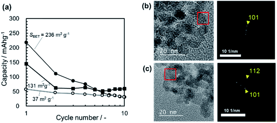 | ||
| Fig. 13 (a) The discharge capacity in the Mg/(borate/G3)/MMO full cells with SBET = 236, 131, and 37 m2 g−1 as a function of the cycle number in a potential range of +0.2 to +4.0 V vs. Mg/Mg2+ at 25 °C. TEM images and the electron diffraction patterns of the MMO particles (b) before and (c) after the 20 cycles in the full cell, Mg/(borate/G3)/MMO, which had been taken from the coin cell. Here, we used the MMO powder calcined for 5 h at 400 °C from the gel aged for 24 h. The spinel structure in the MMO particles was preserved after 20 cycles. | ||
As described in Section 3.2.2 and 3.2.3, the initial abrupt degradation in cyclability was not observed in the half cell with the carbon negative electrode, irrespective of the electrolyte chemicals, such as Mg(ClO4)2/AN with a limited potential window, ΔE = 2.0 V, or Mg[B(HFIP)4]2/G3 with a wide potential window, ΔE = 3.6 V. Thus, the initial degradation in cyclability is anticipated to be related to issues on the Mg negative electrode in the full cell. Actually, it was found that several pinholes were observed in the Mg negative electrode after the cycles (Fig. S12 in the ESI†). The TEM observation indicated that the MMO particles, which had been taken from the coin cell after the cycle test, preserved the spinel structure for at least 20 cycles (Fig. 13b and c). XRD measurements also support that the spinel structure was preserved after the cycle test in the Mg/(borate/G3)/MMO full cell, as well as in the C/(perchlorate/AN)/MMO half cell with no degradation in cyclability (Fig. S13 in the ESI†).
Regarding the Mg[B(HFIP)4]2/G3 electrolyte, the wide potential window, ΔE = 3.8 V (+0.2 to +4.0 V vs. Mg/Mg2+), might be little bit of a severe condition when cycling many times. However, when SBET < 50 m2 g−1, the reversibility in the discharge/charge reactions was preserved in the initial 10 cycles, implying that the electrolyte itself is not directly related to the early cyclability degradation. According to the cyclic voltammograms (Fig. S14 in the ESI†) for the Mg/(borate/G3)/MMO system, the electrolyte was not decomposed in the potential range.
These facts are very interesting; the degradation in cyclability might be caused by some issues around the Mg negative electrode that would be induced by the large SBET of the MMO powder in the positive electrode. The mechanism will be discussed in the next section.
3.2.3.3 Discussion of cyclability degradation. In the 2-electrode coin cell, the amount of charge transfer at the MMO positive electrode has to be equivalent to that at the Mg negative electrode, while the area of the electrochemical reaction interface on the former is much larger than that on the latter. For example, we used approximately 3 mg of the MMO powder with SBET > 200 m2 g−1 in the positive electrode. The actual surface area was estimated to be over Scoin = 6000 cm2, while the Mg electrode was 0.69 cm2 in the coin cell.
Fig. 14a shows the change in discharge capacity with cycling as a function of SBET. Here, in the right vertical axis, the areal capacity on the Mg electrode is indicated, in which the amount of Mg insertion into the MMO particles is assumed to be identical to the amount of charge transfer during the Mg stripping into the electrolyte. In Area I, with SBET < 50 m2 g−1 (Scoin < 1500 cm2), the discharge/charge operation is mostly reversible, with no abrupt decrease in the discharge capacity cycled. In Area II, with 50 m2 g−1 < SBET < 140 m2 g−1 (1500 cm2 < Scoin < 4200 cm2), the discharge capacity decreases abruptly from the 1st to the 2nd cycle but is suppressed from then on. In Area III, with SBET > 140 m2 g−1 (Scoin > 4200 cm2), the discharge capacity decreases drastically from the 1st to the 2nd cycle and diminishes continuously. In this case, the areal capacity of Mg stripping, required for the 1st discharge capacity into the MMO particles, is estimated to be approximately 0.6–1.1 mA h cm−2 on the Mg electrode, which is much larger than the value of 0.4 mA h cm−2 for practical Mg battery use.11
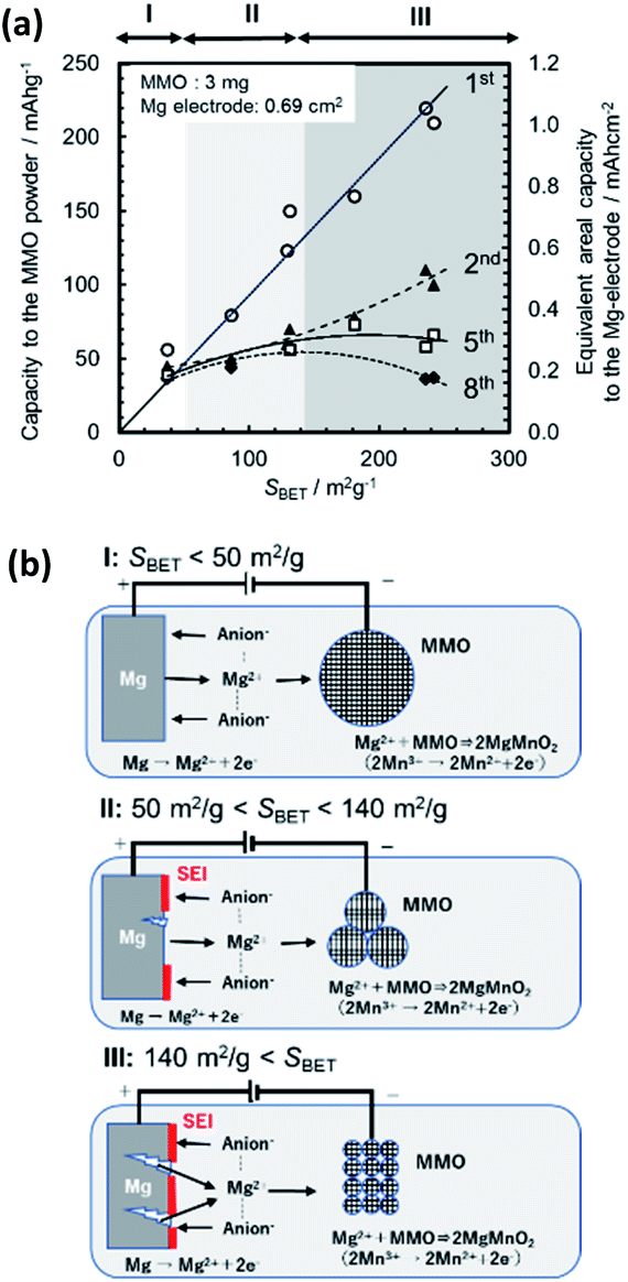 | ||
| Fig. 14 (a) Changes in the discharge capacity of the MMO powders (left vertical axis) and the areal capacity corresponded to the Mg electrode (right vertical axis) from the 1st to 8th cycles as a function of the SBET of the MMO powders in the Mg/(borate/G3)/MMO full cell, and (b) illustrations of the cyclability-degradation models in Area I: SBET < 50 m2 g−1, II: 50 m2 g−1 < SBET < 140 m2 g−1, and III: SBET > 140 m2 g−1. In Area I, the discharge/charge is reversible, with little damage to the Mg electrode. In Area III, the discharge capacity decreased abruptly, and the Mg electrode was damaged due to the larger areal capacity, or, essentially, the large amount of charge transfer for Mg stripping. Area II is an intermediate state between Areas I and III. | ||
The MMO powder with a large SBET above 200 m2 g−1 consisted of fine particles smaller than 8 nm. The particle size might affect the surface chemistry nature, such as the defect density or deterioration of crystallinity. However, we found the wide-ranged linear relation between SBET and the 1st discharge capacity. This fact suggests that the electro-chemical reaction is mainly controlled by the surface area between the MMO particles and the electrolyte.
Fig. 14b illustrates a model of the cyclability degradation in the rechargeable Mg battery of Mg/(borate/G3)/MMO for Areas I–III. In Area I, the 1st discharge capacity on the MMO powder is below 50 mA h g−1. Eventually, this requires the areal capacity to be below 0.22 mA h cm−2 of that of the Mg stripping from the Mg electrode. The reversible stripping/plating of Mg to the Mg[B(HFIP)4]2/G3 electrolyte could proceed with little damage to the Mg negative electrode in the cycles. In Area III, on the other hand, the 1st discharge capacity of the MMO powders is over 200 mA h g−1, requiring an areal capacity of over 1.0 mA h cm−2 for Mg stripping from the Mg electrode. This would damage the Mg electrode, such as abnormal Mg stripping at particular spots, creating pinholes and the deposition of resistive SEI due to anion decomposition.11 Therefore, in the charge step that followed, the Mg ions extracted from the MMO particles could not be plated on the damaged Mg electrode, resulting in losses of the discharge capacity and the charge potential. As the cycle was repeated, the situation would become worse and worse. Area II is an intermediate state between Areas I and III.
This ironic result is a thorny issue with regard to the room-temperature operation of the coin cell, but it is clear that a simple solution is to enlarge the active surface area of the Mg electrode corresponding to the increased SBET of the MMO powders in the coin cell. A Mg electrode composed of Mg nanoparticles has been proposed for the MoS2 positive electrode.34 Chemical modification of the electrolyte to enhance the Mg stripping/plating rate would also improve cyclability at 25 °C.
4. Conclusion
Room-temperature operation of a rechargeable Mg coin cell was evaluated mainly as a function of the SBET of MMO powders, which were obtained via the modified sol–gel method with propylene oxide-driven complex polymerization. Through ultrasonically irradiated quick sol–gel transition and using controlled gel-aging time, seven types of MMO powders were prepared, and a typical MMO powder pasted in the positive electrode had a large SBET (>200 m2 g−1) and more than 90% porosity with a triple-tiered open-channel network.In both the half cells with a carbon negative electrode and the full cell with a Mg negative electrode, the initial discharge capacity increased linearly with the increasing SBET with a Mg[B(HFIP)4]2/G3 electrolyte in a wide potential window, such as ΔE = 3.8 V (+0.2 to +4.0 V vs. Mg/Mg2+) but not with the Mg(ClO4)2/AN electrolyte in a limited potential window, ΔE = 2.0 V (−1.0 to +1.0 V vs. CE, or +1.6 to +3.6 V vs. Mg/Mg2+). Eventually, by using the porous MMO powder with SBET = 236 m2 g−1, a maximum discharge capacity of 220 mA h g−1 was confirmed at 25 °C from the full cell with the Mg[B(HFIP)4)2]/G3 electrolyte. The triple-tiered 3D open-channel structure in the MMO powder was also the key factor in providing sufficient space for delivering the viscous electrolyte to the MMO particles.
Cyclability, however, degraded with the increasing SBET in the full cell with a Mg electrode but not in the half cell with a carbon electrode, irrespective of the electrolyte chemicals. The initial degradation in cyclability was anticipated to be related to some issues with the Mg negative electrode in the full cell. Actually, several pinholes were observed in the Mg negative electrode after the cycles, while the spinel structure in the MMO particles was preserved, according to TEM and XRD observations.
In our proposed model, cyclability degradation might be induced by the huge difference in the total surface area of the MMO powder as compared to that of the Mg film electrode. MMO with a large SBET brings in a large initial discharge capacity, such as >200 mA h g−1, but requires the equivalent large amount of Mg ions stripped from the Mg electrode with an areal capacity over 1.0 mA h cm−2. This might damage the Mg electrode cycle by cycle. This ironic result is a thorny issue with regard to the room-temperature operation of a rechargeable Mg coin-cell battery. However, it is clear that one solution might be to enlarge the active surface area of the Mg electrode corresponding to an increase in the SBET of the MMO powders. We are now trying to find out the proof of the proposed mechanism. For example, the effect of the Mg negative electrode area would be studied in the next step.
Conflicts of interest
There are no conflicts to declare.Acknowledgements
This work was supported by JST ALCA-SPRING Grant Number JPMJAL1301, Japan. We thank Prof. Kiyoshi Kanamura (Tokyo Metropolitan University) and his research group for their kind support in measurements.References
- K. Shafique, B. A. Khawaja, F. Sabir, S. Qazi and M. Mustaqim, IEEE Access, 2020, 8, 23022–23040 Search PubMed.
- P. P. K. Dutta, S. Nilanjan, M. Bulbul, P. Sanjeevikumar, M. Aranyak, U. B. Kumar, H.-N. Jens Bo and C. Prasenjit, IEEE Access, 2019, 7, 182113–182172 Search PubMed.
- S. K. Sharma, I. Woungang, A. Anpalagan and S. Chatzinosas, IEEE Access, 2020, 8, 56948–56991 Search PubMed.
- Y. Ma, Energy Environ. Mater., 2018, 1, 148–173 CrossRef CAS.
- H. Mahammad, A. Hoque, M. Murshadul, H. Aini, Y. Yushaizad and K. P. Jern, IEEE Access, 2018, 6, 19362–19378 Search PubMed.
- W. Xu, J. Wang, F. Ding, X. Chen, E. Nasybulin, Y. Zhang and J.-G. Zhang, Energy Environ. Sci., 2014, 7, 513–537 RSC.
- J. Muldoon, C. B. Bucur and T. Gregory, Chem. Rev., 2014, 114, 11683–11720 CrossRef CAS.
- P. Canepa, S. Gautam, D. C. Hannah, M. Liu, K. G. Gallagher, K. A. Persson and G. Cede, Chem. Rev., 2017, 117, 4287–4341 CrossRef CAS.
- Y. Zhanga, H. Gengb, W. Weia, J. Mac, L. Chena and C. C. Li, Energy Storage Mater., 2019, 20, 118–138 CrossRef.
- J. Muldoon, C. B. Bucur and T. Gregory, Angew. Chem., Int. Ed., 2017, 56, 12064–12084 CrossRef CAS.
- H. D. Yoo, S. Han, I. L. Bolotin, G. M. Nolis, R. D. Bayliss, A. K. Burrell, J. T. Vaughey and J. Cabana, Langmuir, 2017, 33, 9398–9406 CrossRef CAS.
- H. D. Yoo, I. Shterenberg, Y. Gofer, G. Gershinsky, N. Pour and D. Aurbach, Energy Environ. Sci., 2013, 6, 2265–2279 RSC.
- D. Aurbach, Z. Lu, A. Schechter, Y. Gofer, H. Gizbar, R. Turgeman, Y. Cohen, M. Moshkovich and E. Lev, Nature, 2000, 407, 724–727 CrossRef CAS.
- P. G. Bruce, F. Krok, J. Nowinski, V. C. Gibson and K. Tavakkoli, J. Mater. Chem., 1991, 1, 705–706 RSC.
- G. Gershinsky, H. D. Yoo, Y. Gofer and D. Aurbach, Langmuir, 2013, 29, 10964–10972 CrossRef CAS.
- M. Liu, Z. Rong, R. Malik, P. Canepa, A. Jain, G. Ceder and K. A. Persson, Energy Environ. Sci., 2015, 8, 964–974 RSC.
- K. Shimokawa and T. Ichitsubo, Curr. Opin. Electrochem., 2020, 21, 93–99 CrossRef CAS.
- S. Okamoto, T. Ichitsubo, T. Kawaguchi, Y. Kumagai, F. Oba, S. Yagi, K. Shimokawa, N. Goto, T. Doi and E. Matsubara, Adv. Sci., 2015, 2, 1500072 CrossRef.
- Q. D. Truong, M. K. Devaraju, P. D. Tran, Y. Gambe, K. Nayuki, Y. Sasaki and I. Honma, Chem. Mater., 2017, 29, 6245–6251 CrossRef CAS.
- C. Kim, P. J. Phillips, B. Key, T. Yi, D. Nordlund, Y. Yu, R. D. Bayliss, S. Han, M. He, Z. Zhang, A. K. Burrell, R. F. Klie and J. Cabana, Adv. Mater., 2015, 27, 3377–3384 CrossRef CAS.
- Q. D. Truong, H. Kobayashi, K. Nayuki, Y. Sasaki and I. Honma, Solid State Ionics, 2020, 344, 115136 CrossRef CAS.
- W. Chen, X. Zhan, B. Luo, Z. Ou, P.-C. Shih, L. Yao, S. Pidaparthy, A. Patra, H. An, P. V. Braun, R. M. Stephens, H. Yang, J. Zuo and Q. Chen, Nano Lett., 2019, 19, 4712–4720 CrossRef CAS.
- K. Ishii, S. Doi, R. Ise, T. Mandai, Y. Oaki, S. Yagi and H. Imai, J. Alloys Compd., 2020, 826, 152556 CrossRef.
- M. F. Rahman and D. Gerosa, Optoelectron. Adv. Mater., Rapid Commun., 2015, 9, 1204–1207 CAS.
- O. Tutusaus, R. Mohtadi, T. S. Arthur, F. Mizuno, E. G. Nelson and Y. V. Sevryugina, Angew. Chem., Int. Ed., 2015, 54, 7900–7904 CrossRef CAS.
- R. Jay, A. W. Tomich, J. Zhang, Y. Zhao, A. D. Gorostiza, V. Lavallo and J. Guo, ACS Appl. Mater. Interfaces, 2019, 11, 11414–11420 CrossRef CAS.
- T. Mandai, K. Tatesaka, K. Soh, H. Masu, A. Choudhary, Y. Tateyama, R. Ise, H. Imai, T. Takeguchia and K. Kanamura, Phys. Chem. Chem. Phys., 2019, 21, 12100–12111 RSC.
- R. Deivanayagam, B. J. Ingram and R. Shahbazian-Yassar, Energy Storage Mater., 2019, 21, 136–153 CrossRef.
- Z. Zhao-Karger, M. Bardaji, O. Fuhr and M. Fichtner, J. Mater. Chem., 2017, 5, 10815–10820 RSC.
- A. Shyamsunder, L. E. Blanc, A. Assoud and L. F. Nazar, ACS Energy Lett., 2019, 4, 2271–2276 CrossRef CAS.
- M. Zhang, S. Guo, L. Zheng, G. Zhang, Z. Hao, L. Kang and Z. Liu, Electrochim. Acta, 2013, 87, 546–553 CrossRef CAS.
- M. Kubo, Y. Oumi, R. Miura, A. Stirling, A. Miyamoto, M. Kawasaki, M. Yoshimoto and H. Koinuma, J. Chem. Phys., 1997, 107, 4416–4422 CrossRef CAS.
- D. Kim, S. C. Jung, S. Ha, Y. Kim, Y. Park, J. H. Ryu, Y. Han and K. T. Lee, Chem. Mater., 2018, 30, 3199–3203 CrossRef CAS.
- Y. Liang, R. Feng, S. Yang, H. Ma, J. Liang and J. Chen, Adv. Mater., 2011, 23, 640–643 CrossRef CAS.
Footnote |
| † Electronic supplementary information (ESI) available: Illustrations of the MMO powder preparation (Fig. S1); illustrations of the Mg coin-cell structure (Fig. S2); cyclic voltammograms for the Mg(ClO4)2/AN electrolyte using the MMO positive electrode with and without the V2O5 coating (Fig. S3); current–voltage characteristics for the Mg[B(HFIP)4]2/G3 electrolyte and the cyclic voltammogram of the Mg/(borate/G3)/MMO system (Fig. S4); pore-size distributions, cumulative pore volumes, and SBET for the MMO powders (Fig. S5 and S7); TG/DTA profiles of the dried gel (Fig. S6); an Arrhenius plot of SBET and DBET for the MMO powders (Fig. S8); open circuit voltages and the average discharged potentials at 25 °C in the 1st cycle for the full cell of Mg/(borate/G3)/MMO (Fig. S9); discharge capacity at 25 °C in the 1st cycle for the full cell of Mg/(borate/G3)/MMO (Fig. S10); discharge capacities as a function of the maximum charging voltage in the full cell of Mg/(borate/G3)/MMO (Fig. S11); photographs of the Mg-alloy negative electrode and the separator in the full cell of Mg/(borate/G3)/MMO (Fig. S12); changes in the XRD patterns of the MMO powders in the half cell, Mg/(perchlorate/AN)/MMO and the full cell, Mg/(borate/G3)/MMO (Fig. S13); cyclic voltammograms for Mg/(borate/G3)/MMO (Fig. S14). See DOI: 10.1039/d0ta07974j |
| This journal is © The Royal Society of Chemistry 2021 |