 Open Access Article
Durable photoelectrochemical CO2 reduction with water oxidation using a visible-light driven molecular photocathode†
Ryutaro
Kamata
a,
Hiromu
Kumagai‡
 a,
Yasuomi
Yamazaki§
 a,
Masanobu
Higashi¶
b,
Ryu
Abe
 b and
Osamu
Ishitani
 *a
*a
aDepartment of Chemistry, School of Science, Tokyo Institute of Technology, O-okayama 2-12-1-NE-1, Meguro-ku, Tokyo 152-8550, Japan. E-mail: ishitani@chem.titech.ac.jp
bDepartment of Energy and Hydrocarbon Chemistry, Graduate School of Engineering, Kyoto University, Katsura, Nishikyo-ku, Kyoto 615-8510, Japan
First published on 21st October 2020
Abstract
Photocatalytic reduction of CO2 using water as a reductant and visible light as the energy source is an important target in artificial photosynthesis. In this study, we report a highly stable photoelectrochemical CO2 reduction involving a new molecular photocathode comprising a NiO electrode and polymerized complexes of the Ru(II) photosensitizer and Ru(II) catalyst (NiO/PRu-poly-Ru-RuCAT1). CO and HCOOH were stably and selectively produced for over 100 h under visible light irradiation and a low bias. The turnover number of CO2 reduction products exceeded 1200, which represents the highest durability reported for photoelectrochemical reactions using molecular photocathodes. Moreover, a connected system of the NiO/PRu-poly-Ru-RuCAT1 molecular photocathode and a CoOx/BiVO4 photoanode suitable for water oxidation facilitated stable CO2 reduction with water as an electron donor and visible light as the energy source, with no bias for over 24 h. An energy conversion efficiency of 1.7 × 10⁻²% was obtained, which is the highest value reported for visible light driven systems utilizing a molecular photocatalyst for CO2 reduction with water as the reductant.
Introduction
Artificial photosynthesis is an attractive research field because of its potential to resolve three serious problems facing mankind; global warming, shortage of energy resources, and carbon resource scarcity. Therefore, photocatalytic reduction of CO2 with water as a reductant and visible light as the energy source is one of the most important aims in artificial photosynthesis research. Few systems achieve this reaction without employing expensive tandem-type solar cells, with the carbon and electron sources clearly determined. Morikawa and his co-workers reported systems which consisted of two types of semiconductor photoelectrodes, one p-type InP semiconductor photocathode with a Ru(II) carbonyl complex as a catalyst for CO2 reduction and another TiO2 photoanode.1 The efficiency of this type of photoelectrochemical cell for CO2 reduction has been improved, such as using a coupled system of a reduced SrTiO3 photoanode for water oxidation and a TiO2/N,Zn-Fe2O3/Cr2O3 photocathode with a Ru(II)-complex as a catalyst for CO2 reduction.2 However, the photoanode of these systems cannot absorb visible light. Recently, Morikawa, Kudo, and colleagues also reported a mixed system of two types of semiconductor particles, i.e., (CuGa)1−xZn2xS2 and BiVO4. In this system, the Ru(II) complex was again used as the catalyst for CO2 reduction.3 The reported systems exhibit a low selectivity of CO2 reduction against H2 evolution and insufficient durability. It is again emphasized that, in these systems, light absorbers are the semiconductor materials, and the Ru(II) complex works only as the catalyst.We recently reported novel types of molecular photocathodes consisting of supramolecular photocatalysts with two types of metal complexes as redox photosensitizer (PS) and catalyst (CAT) units in one molecule and a p-type semiconductor electrode like NiO and CuGaO2 which has no or weak absorption in the visible region.4–7 These molecular photocathodes can reduce CO2 under visible light irradiation and a relatively low-applied potential. The photocatalytic reactions were initiated by the excitation of only the PS unit of the supramolecular photocatalyst and not by excitation of the semiconductor material. These new molecular photocathodes should be advantageous over the systems coupling two semiconductor materials as light absorbers and a mononuclear metal complex only as a catalyst. We can easily change the absorption wavelength and the ability of the photocathode by changing the PS unit of the supramolecular photocatalysts on the electrode. Since intramolecular electron transfer rapidly proceeds from the reduced PS unit to the CAT unit,8,9 the electrons supplied from the semiconductor electrode to the PS unit can be efficiently and rapidly transferred to the CAT unit. Since the distance between the CAT unit of the supramolecular photocatalyst and the electrode is larger compared to the photocathode where the mononuclear metal complex as the CAT was directly attached on the electrode, the back-electron-transfer from the reduced CAT to the electrode, which lowers the efficiency of the photocathodic reaction, can be suppressed. Moreover, since the excited states of the PS units such as the Ru(II) trisdiimine complexes have stronger oxidation power compared to those of p-type semiconductors such as InP, visible-driven photoanodes such as TaON and BiVO4 can be potentially coupled as photoanodes for water oxidation.
We reported photoelectrochemical cells comprising this new type of molecular photocathode and a visible-light driven n-type semiconductor photoanode for H2O oxidation in CO2 reduction i.e. water serves as an electron donor and visible light as the energy source.5,6 These are the sole examples of using a supramolecular photocatalyst for CO2 reduction with water as a reductant and visible light as energy. However, the reaction durability of these molecular photocathodes is still insufficient; the reaction rate of the system significantly decreases within a few hours. This low stability is primarily attributed to the desorption of the supramolecular photocatalyst from the semiconductor electrode during the photoreaction. Notably, such desorption of the metal complex has been frequently highlighted as an essential problem in the metal complex–semiconductor hybrids,10–13 owing to insufficient adsorption by the anchoring groups such as phosphonic and carboxylic acids in water solutions, especially during photoredox reactions.
To solve this problem, several methods such as stabilization by polymerization of a metal complex,1,7,14–20 formation of an overlayer by atomic layer deposition,21–23 and amide coupling using surface-decorated silatrane anchoring groups24 are proposed. For example, molecular photocathodes prepared through adsorption of Ru(II) PS and Re(I) CAT units by electropolymerization have been reported by our and Meyer's groups.7,20 These photocathodes facilitate relatively stable photoreactions compared to those using only anchoring groups. Nevertheless, the improved stability remains limited; their photocurrent is maintained for several hours but decreases over longer irradiation owing to the splitting of the Re–C bonds, which were made in the side reaction during the electropolymerization,7 causing the metal complexes to be soluble in the reaction solution. So far, no attempt has increased the reaction time beyond 15 h, and the turnover numbers (TON) for CO2 reduction were usually less than 100.5–7,20 Therefore, an optimized design is required for the synthesis of the molecular photocathode for CO2 reduction, to improve durability.
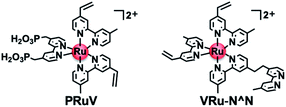
Herein, we report a highly durable and efficient photoelectrochemical CO2 reduction using a novel molecular photocathode (NiO/PRu-poly-Ru-RuCAT1) prepared by a new three-step procedure (Scheme 1), which does not produce by-products of the metal–carbon bonds. First, the Ru trisdiimine-type photosensitizer complex (PRuV, Fig. 1), containing both methyl phosphonic acid groups and vinyl groups on the diimine ligands, was adsorbed by methyl phosphonic acid groups on a NiO electrode. Another Ru mononuclear complex possessing diimine ligands with a vinyl group and a non-coordinated diimine ligand (VRu-N^N, Fig. 1) was connected by electropolymerization of the vinyl groups. These procedures induced the rigid attachment of the polymerized Ru redox photosensitizer complexes with a non-coordinated diimine ligand onto the NiO electrode and increased the amount of the attached Ru photosensitizer units. Finally, a Ru catalyst unit was introduced into the non-coordinated diimine ligand, forming [(N^N)2Ru(bpyC2bpy)Ru(CO)2Cl2]2+-type complexes (N^N = diimine ligand, bpyC2bpy = 1,2-bis(4′-methyl-[2,2′-bipyridine]-4-yl)ethane) on the electrode, which were reported as durable supramolecular photocatalysts for CO2 reduction in homogeneous solutions25 and hybrid systems with various semiconductor particles.10–13 This three-step procedure prevented structural changes of the catalyst unit during the electropolymerization. The NiO/PRu-poly-Ru-RuCAT1 molecular photocathode displayed excellent stability for the photoelectrochemical CO2 reduction with an applied bias at E = −0.7 V vs. Ag/AgCl for longer than 100 h. This is the most stable molecular photocathode up to now. In addition, combining this molecular photocathode with a suitable semiconductor photoanode yielded stable photocatalytic CO2 reduction using water as an electron donor and visible light as an energy source, without bias for over 24 h.
Results and discussion
Preparation of NiO/PRu-poly-Ru-RuCAT1
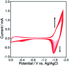
NiO electrodes were prepared by coating a NiO film on fluorine doped tin oxide (FTO) electrodes (active area: 2.5 cm2).4 NiO/PRuV was prepared by a simple adsorption method via dipping the NiO electrode into an MeCN solution containing PRuV overnight. This was used as a working electrode for electropolymerization of the Ru complexes, using a three-electrode system in an Ar-purged MeCN solution containing VRu-N^N and a tetraethylammonium tetrafluoroborate (Et4NBF4) supporting electrolyte. The potential was scanned between 0 V and −1.9 V (vs. Ag/AgNO3) at a scan rate of 100 mV s−1 for 20 cycles during the polymerization. Current corresponding to redox reactions of the Ru(II) photosensitizer units was evident between −1.3 V and −1.9 V, increasing with the number of sweep cycles (Fig. 2). These results suggest that VRu-N^N polymerized and adsorbed on the electrode, producing NiO/PRu-poly-Ru-N^N.7 Scanning electron microscopy (SEM) images of NiO and NiO/PRu-poly-Ru-N^N reveal that the Ru complex polymer formed on the surface and inside the layer among the NiO particles (Fig. 3). Fig. 4 shows the results from time-of-flight secondary ion mass spectrometry (TOF-SIMS), demonstrating the distribution of elements in the depth direction for specimens of NiO, NiO/PRuV, and NiO/PRu-poly-Ru-N^N. The sputter times on the horizontal axis correspond to the cross-sectional components in the depth direction of the electrode. The relatively higher intensity of Ru+ species throughout the entire range was confirmed for NiO/PRuV and NiO/PRu-poly-Ru-N^N, whereas the polymer prepared by the previously reported synthesis method showed the non-uniform distribution of Ru near the surface of the NiO layer of the electrode.7 This clearly indicates that the Ru complex penetrates the NiO film layer by adsorbing PRuV and following the electropolymerization of VRu-N^N.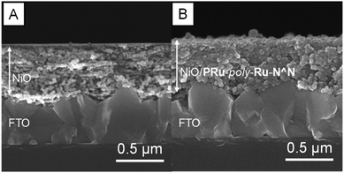 | ||
| Fig. 3 Cross-sectional scanning electron microscopy (SEM) images of (A) the NiO electrode and (B) NiO/PRu-poly-Ru-N^N. | ||
The UV-vis absorption spectrum of NiO/PRu-poly-Ru-N^N shows a characteristic absorption maximum at around 464 nm, which is attributed to the singlet metal-to-ligand-charge-transfer (1MLCT) absorption band of the Ru photosensitizer unit (Fig. 5A, S1†). This absorbance of NiO/PRu-poly-Ru-N^N is significantly higher than that of NiO/PRuV. These results demonstrate that the electropolymerized complexes maintained the structure of the Ru photosensitizer unit in NiO/PRu-poly-Ru-N^N, and more photosensitizer units were introduced into and on the electrode by the electropolymerization compared to those involving only methyl phosphonic acid groups, i.e., NiO/PRuV.
The RuII(N^N)(CO)2Cl2-type catalyst was formed with the non-coordinated diimine ligand of the NiO/PRu-poly-Ru-N^N electrode by dipping the electrode into an MeCN solution containing [Ru(CO)2Cl2]n as a precursor for 1–2 day(s). No difference is obvious between the UV-vis absorption spectra of the electrode before (NiO/PRu-poly-Ru-N^N, Fig. S2†) and after introducing the catalyst (NiO/PRu-poly-Ru-RuCAT1). This is reasonable because the RuII(N^N)(CO)2Cl2-type complexes exhibit only weak or no absorption in this range (Fig. S1†). Fig. 5B and C show spectra from X-ray photoelectron spectroscopy (XPS) and FT-IR, respectively. The XPS spectrum of NiO/PRu-poly-Ru-RuCAT1 displays a peak attributed to Cl 2p, which is not observed for NiO/PRu-poly-Ru-N^N, indicating introduction of the Ru catalyst units into the electrode. The FT-IR spectrum for NiO/PRu-poly-Ru-RuCAT1 shows three prominent broad peaks at 2056 cm−1, 1993 cm−1, and 1976 cm−1 attributed to carbonyl stretching vibrations, whereas none is observed for NiO/PRu-poly-Ru-N^N. The peak at 1993 cm−1 corresponds to the cis-(CO)-trans-(Cl)–Ru(N^N)(CO)2Cl2 vibration, consistent with that of [cis-(CO)-trans-(Cl)–Ru(dmb)2(bpyC2bpy)Ru(CO)2Cl2](PF6)2 (Ru-RuCAT: dmb = 4,4′-dimethyl-2,2′-bipyridyl) drop-cast on the NiO electrode (black dotted line in Fig. 5C). The difference spectrum between NiO/PRu-poly-Ru-RuCAT1 and Ru-RuCAT (2058, 1991 cm−1) gives two peaks at 2049 and 1970 cm−1, suggesting the formation of another Ru(II) complex with the carbonyl ligands. This is likely a cis-(CO)-cis-(Cl)–Ru(N^N)(CO)2Cl2-type complex, because such an isomer is known as a by-product in the synthesis of cis-(CO)-trans-(Cl)–Ru(N^N)(CO)2Cl2, and displays two CO vibrational peaks with lower wavenumbers than those of cis-(CO)-trans-(Cl)–Ru(dmb)(CO)2Cl2.26–28 From these results, we concluded that Ru catalyst units were introduced through coordination bonds with the free diimine unit of NiO/PRu-poly-Ru-N^N. Note that cis-(CO)-cis-(Cl)–Ru(N^N)(CO)2Cl2 also acts as a CO2 reduction catalyst like isomer cis-(CO)-trans-(Cl)–Ru(N^N)(CO)2Cl2.26,27
The total amounts of the Ru photosensitizer and the Ru catalyst on the electrode are 34 and 15 nmol cm−2, respectively (see Experimental for calculation details).
Photoelectrochemical properties
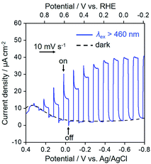
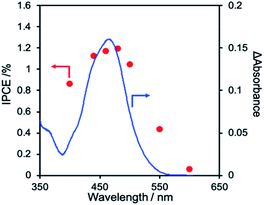
Fig. 6 shows the current–potential curves of NiO/PRu-poly-Ru-RuCAT1 in a CO2-purged aqueous solution containing NaHCO3 (50 mM) during irradiation at λex > 460 nm or under dark conditions. Under the irradiation, the cathodic photocurrent was observed from E = ∼+0.3 V vs. Ag/AgCl, and increased with scanning to a more negative potential. A reasonable agreement exists between the action spectrum of the incident photon to current conversion efficiency (IPCE) and the UV-vis absorption spectrum of the Ru photosensitizer unit on NiO/PRu-poly-Ru-RuCAT1 (Fig. 7). This suggests that the cathodic photocurrent is generated by the photoexcitation of the Ru photosensitizer unit. The maximum IPCE of NiO/PRu-poly-Ru-RuCAT1 is 1.2% at E = −0.7 V vs. Ag/AgCl under irradiation at λex = 480 nm.Photoelectrochemical CO2 reduction
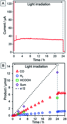
The NiO/PRu-poly-Ru-RuCAT1 electrode at an applied bias of −0.7 V vs. Ag/AgCl (corresponding to −0.11 V vs. RHE), irradiated at λex > 460 nm under a CO2 atmosphere, yielded CO and HCOOH as main products, and H2 as a by-product. Fig. 8A shows the time course of the photocurrent for 24 h of irradiation, without any decrease even after 24 h. The formation rate of reduction products was also maintained during the 24 h (Fig. 8B), with turnover numbers (TONs) 176, 135, and 30 for CO (6.5 μmol), HCOOH (5.0 μmol), and H2 (1.1 μmol), respectively after 24 h irradiation (see Experimental for calculation details). The carbon source of the produced CO and HCOOH was confirmed as CO2 by 13CO2 isotope-labelling experiments (Fig. 9). The faradaic efficiency (Fred, 87%) and the selectivity of CO2 reduction (91%) were very high even in the aqueous solution.Almost no change was observed in the UV-vis absorption spectrum of the photocathode even after 24 h irradiation (Fig. 10A). This indicates no decomposition or desorption of the Ru photosensitizer unit from the electrode during the photocatalytic reaction, highlighting durable photoelectrochemical CO2 reduction. XPS and FT-IR spectroscopy were used for checking the RuCAT1 units of the photoelectrode after the photocatalytic reaction. The XPS spectrum was characterized by disappearance of the Cl 2p peak (Fig. 10B). Although CO stretching bands with similar strengths are present in the FT-IR spectrum, their wavenumbers changed to 2030, and 1955 cm−1 (Fig. 10C). These results indicate substitution of the Cl ligands of the RuCAT1 unit with other ligands, which is consistent with previous reports describing the behaviours of Ru(N^N)(CO)2Cl2-type catalysts during photocatalytic CO2 reduction reactions in homogeneous solutions.29 The shifts toward lower wavenumbers of the peaks in the FT-IR spectrum reflect coordination of higher electron donating ligands than Cl−, such as HCOO− and/or OH−. It is noteworthy that the Ru(0) polymer [Ru(diimine)(CO)2]n which shows νCO bands at 2035 and 2084 cm−1 was not observed. Although such polymerization of the [Ru(diimine)(CO)2Cl2] type complexes during photocatalytic reduction of CO2 in homogeneous solutions was reported as a deactivation process of the photocatalysis, in the photoelectrochemical system, the Ru complexes cannot freely move on the electrode resulting in suppression of this deactivation process of the Ru catalyst unit.
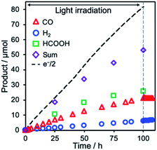
Remarkably, photocatalytic CO2 reduction continued even after 100 h irradiation (Fig. 11). Although the faradaic efficiency gradually decreased to 65% after 100 h irradiation because of the slow penetration of air into the closed cell and resulting electron consumption via the reduction of O2, production of CO and HCOOH continued without significant reduction in their selectivity (entries 1–3 in Table 1). The total TON of the photocatalytic CO2 reduction exceeded 1200 (TONCO = 576, TONHCOOH = 695, TONH2 = 172), representing the highest TON reported for CO2 reduction using molecular photocathodes, to the best of our knowledge.
| Entry | Electrode | Irradn. time | E | Products/μmol (Fred) | |||||
|---|---|---|---|---|---|---|---|---|---|
| h | V Ag/AgCl | V RHE | CO | HCOOH | H2 | Total | e−/2 | ||
| a Electrodes (electrode area: 2.5 cm2) in aqueous solutions containing NaHCO3 (50 mM, pH = 6.6) irradiated at 460 nm < λex < 650 nm using a 300 W Xe lamp (27 mW cm−2). b vs. Ag/AgCl (sat. KCl aq). c vs. RHE. d Data from ref. 7. e n.d.: not detected. | |||||||||
| 1 | NiO/PRu-poly-Ru-RuCAT1 | 5 | −0.7 | −0.11 | 1.1 (35) | 1.2 (39) | 0.2 (6) | 2.5 (81) | 3.1 |
| 2 | NiO/PRu-poly-Ru-RuCAT1 | 24 | −0.7 | −0.11 | 6.5 (45) | 5.0 (34) | 1.1 (8) | 12.6 (87) | 14.5 |
| 3 | NiO/PRu-poly-Ru-RuCAT1 | 100 | −0.7 | −0.11 | 21.3 (26) | 25.7 (31) | 6.3 (8) | 53.3 (65) | 82.0 |
| 4 | NiO/PRu-poly-Ru-RuCAT1 | 5 | −0.3 | +0.29 | 0.7 (32) | 0.9 (41) | 0.1 (5) | 1.7 (77) | 2.2 |
| 5 | NiO/PRu-poly-Ru-RuCAT1 | 5 | 0 | +0.59 | 0.1 (18) | 0.3 (37) | 0.05 (7) | 0.5 (62) | 0.8 |
| 6 | NiO/PRu-poly-Ru-N^N | 5 | −0.7 | −0.11 | Trace | 0.1 (13) | 0.3 (38) | 0.4 (49) | 0.8 |
| 7 | NiO/PRu-RuCAT | 5 | −0.7 | −0.11 | 0.03 (5) | 0.2 (45) | 0.05 (9) | 0.3 (59) | 0.5 |
| 8 | NiO/PRu-poly-Ru-RuCAT2 | 5 | −0.7 | −0.11 | 1.2 (43) | 0.5 (18) | 0.2 (7) | 1.9 (67) | 2.8 |
| 9 | NiO/PRu-poly-Ru-RuCAT2 | 24 | −0.7 | −0.11 | 5.5 (58) | 1.1 (12) | 0.3 (3) | 6.9 (73) | 9.5 |
| 10d | NiO/PRu-poly-Ru-Re | 5 | −0.7 | −0.11 | 0.5 (55) | 0.1 (13) | 0.2 (17) | 0.8 (85) | 0.9 |
| 11 | NiO | 5 | −0.7 | −0.11 | n. d.e | n. d.e | 0.01 (5) | 0.01 (5) | 0.2 |
Although the cathodic current and the generated products decreased when the applied bias shifted to more positive i.e., at E = −0.3 V and 0 V (entries 4 and 5 in Table 1, Fig. S3†), the NiO/PRu-poly-Ru-RuCAT1 photocathode still drove the reaction to produce CO and HCOOH. Notably, the potential of 0 V vs. Ag/AgCl (corresponding to +0.59 V vs. RHE), at which the photocathode could generate the detectable products, was more positive than previously reported molecular photocathodes based on NiO, containing the Re(N^N)(CO)3Br-type complex as the catalyst unit. The photoelectrochemical properties are compared between these photocathodes in Fig. S4.†5,7,20 This difference in the practicable potential possibly originates from different catalytic properties of Ru(N^N)(CO)2Cl2 including more positive reduction potential compared to the Re(N^N)(CO)3Br catalyst. This positive shift of the onset potential is advantageous for the CO2 reduction combined with the photoanode for water oxidation.
Effects of assembly methods of the photocathodes on the activity for CO2 reduction
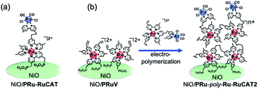
NiO/PRu-poly-Ru-N^N without the catalyst unit hardly proceeded photocatalytic CO2 reduction under 5 h irradiation (entry 6 in Table 1). The decomposition of the Ru photosensitizer unit would produce [Ru(N^N)2(L)(L′)]2+-type complexes, which generate HCOOH at very low efficiency in cooperation with the residual Ru photosensitizer units.25,30 This clearly indicates that the Ru catalyst unit is crucial in the photocatalytic CO2 reduction (Table 1, entry 1 for comparison). It is noteworthy that CO or HCOOH was not detected using a bare NiO electrode (entry 11).Two methods were applied for synthesizing molecular photocathodes comprising similar metal complex units, i.e., [Ru(N^N)3]2+-type photosensitizer and Ru(N^N)(CO)2Cl2-type catalyst units on the NiO electrode. These include: (1) adsorption of the Ru(II)–Ru(II) supramolecular photocatalyst with methyl phosphonic acid groups (PRu-RuCAT, Fig. 12) directly onto the NiO surface (NiO/PRu-RuCAT, Scheme 2a) and (2) electropolymerization of the Ru(II)–Ru(II) supramolecular photocatalyst with vinyl groups on the photosensitizer unit (VRu-RuCAT, Fig. 12) on NiO/PRuV (NiO/PRu-poly-Ru-RuCAT2, Scheme 2b). These methods were reported for the synthesis of molecular photocathodes with another supramolecular photocatalyst containing the [Ru(N^N)3]2+-type photosensitizer and Re(N^N)(CO)3Br-type catalyst units (NiO/PRu-Re4,5 and NiO/PRu-poly-Ru-Re,7 respectively, shown in Scheme S1†).
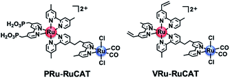 | ||
| Fig. 12 Chemical structures of the metal complexes used for the synthesis of NiO/PRu-RuCAT and NiO/PRu-poly-Ru-RuCAT2. | ||
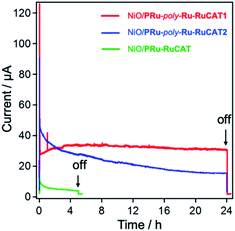
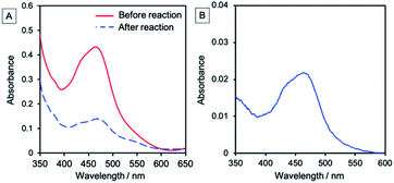
Fig. 13 shows the time courses of photocurrent during photoelectrochemical CO2 reduction using these electrodes and NiO/PRu-poly-Ru-RuCAT1 as well. Although lower photocurrent was observed for NiO/PRu-RuCAT, it rapidly declined within a few hours. This small photocurrent and low stability reflect a similar tendency for the previously reported NiO/PRu-Re.4,5 These characteristics are attributed to the low adsorption density of the supramolecular photocatalysts and low adsorption stability of the methyl phosphonic acid anchors on the NiO surface. Much smaller amounts of CO2-reduction products were produced using NiO/PRu-RuCAT compared to products using NiO/PRu-poly-Ru-RuCAT1 (entries 7 and 1 in Table 1 for comparison).
In the initial stage of the photocatalytic reaction using NiO/PRu-poly-Ru-RuCAT2, the photocurrent was similar to that using NiO/PRu-poly-Ru-RuCAT1, however, the current value gradually decreases from 45 to 15 μA during 24 h irradiation (Fig. 13). The total amounts of CO and HCOOH produced were lower compared to those using NiO/PRu-poly-Ru-RuCAT1 after 24 h irradiation (entries 2 and 9 in Table 1 for comparison). The UV-vis absorption spectrum of NiO/PRu-poly-Ru-RuCAT2 after the reaction showed a decrease in the absorption of the Ru photosensitizer unit (Fig. 14A). In addition, the UV-vis spectrum of the reaction solution after 5 h irradiation clearly indicates the desorption of the Ru(II) complexes from the molecular photocathode to the solution (Fig. 14B). These results suggest that the desorption of some parts of the metal complexes from the electrode leads to the decrease of the photocurrent, as shown in Fig. 13. The FT-IR spectrum of NiO/PRu-poly-Ru-RuCAT2 differed from that of VRu-RuCAT (Fig. S5†), suggesting that the structure of the Ru(N^N)(CO)2Cl2 catalyst unit changed during the electropolymerization. The SEM observations reveal that the polymer film of NiO/PRu-poly-Ru-RuCAT2 mainly attached on the surface of the NiO film (Fig. S6B†), which was different for NiO/PRu-poly-RuCAT1 (Fig. S6A†) but similar for the reported NiO/PRu-poly-Ru-Re (Fig. S6C†).7 The bulkiness of VRu-RuCAT compared to VRu-N^N probably suppressed polymerization within the NiO film. The previous study for NiO/PRu-poly-Ru-Re suggests that the Re catalyst unit released its Br ligand and coordinated with radical species produced from the vinyl group during the electropolymerization, which partially contributed to producing the polymer structure. A similar reaction, i.e., Ru–C bond formation, is expected in the synthesis of NiO/PRu-poly-Ru-RuCAT2. The cleavage of this Ru–C bond and the surface localization of the Ru-RuCAT2 unit on the surface of NiO/PRu-poly-Ru-RuCAT2 probably contributed to eliminating the Ru(II) complexes from the electrode surface during the photocatalytic reduction of CO2. These results clearly highlight the advantage of the newly reported preparation method for NiO/PRu-poly-Ru-RuCAT1, i.e., the stepwise method (electropolymerization and the subsequent introduction of the catalyst unit) successfully prevents the decline of photocatalysis of the molecular photocathode mainly owing to the suppression of the detachment of the molecular photocatalysts from the electrode.
Photoelectrochemical CO2 reduction with water oxidation
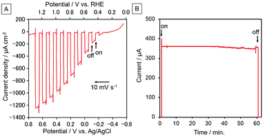
Since NiO/PRu-poly-Ru-RuCAT1 showed the highest photocatalysis for CO2 reduction for the reported molecular photocathodes, a photoelectrochemical cell comprising NiO/PRu-poly-Ru-RuCAT1 with a photoanode for water oxidation was constructed for reducing CO2 with water as an electron donor (Scheme 3). We selected a CoOx-deposited BiVO4 electrode (CoOx/BiVO4), which has good activity for water oxidation under visible light irradiation, enough stability, and a sufficiently negative conduction band to pass electrons to the valence band of NiO.31,32 The photoelectrochemical properties of the CoOx/BiVO4 photoanode were examined using the same solution for the CO2 reduction reaction, i.e., the CO2-purged water solution containing 50 mM NaHCO3 (pH = 6.6). Fig. 15A shows the current–potential curve during irradiation at 400 nm < λex < 650 nm (40 mW cm−2); photoanodic current was generated and the onset potential was much more negative than +0.3 V (vs. Ag/AgCl) which is the onset potential of the NiO/PRu-poly-Ru-RuCAT1 photocathode. Fig. 15B shows the time course of photocurrent under continuous light irradiation (the same reaction conditions described above); stable photoanodic current was observed for 1 h irradiation at E = 0 V vs. Ag/AgCl, and the evolution of O2 was confirmed during the irradiation with a reasonable faradaic efficiency (F = 75%).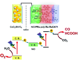 | ||
| Scheme 3 Photoelectrochemical CO2 reduction with water as a reductant and visible light as the energy source by a cell comprising the NiO/PRu-poly-Ru-RuCAT1 photocathode and CoOx/BiVO4 photoanode. | ||
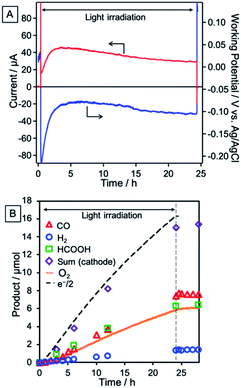
A photoelectrochemical cell consisting of the NiO/PRu-poly-Ru-RuCAT1 molecular photocathode and CoOx/BiVO4 photoanode separated by a Nafion membrane was constructed as illustrated in Scheme 3. The NiO/PRu-poly-Ru-RuCAT1 and CoOx/BiVO4 electrodes were irradiated with visible light (480 nm < λex < 650 nm, 81 mW cm−2 and 400 nm < λex < 650 nm, 61 mW cm−2, respectively) without any applied bias in a CO2-purged NaHCO3 (50 mM) aqueous solution (pH = 6.6), and the photocurrent was observed for 24 h (Fig. 16A). The photocurrent increased initially, reaching its maximum after 3.5 h, similar to the half reaction using NiO/PRu-ply-Ru-RuCAT1 (Fig. 8A and S3†). This would be caused by the structural change of the RuCAT1 catalyst unit in the photocathode. It is noteworthy that about 65% of the photocurrent was maintained even after the 24 h irradiation compared to the maximum. For 24 h, CO (8.0 μmol, TONCO = 219) and HCOOH (6.4 μmol, TONHCOOH = 175) continuously formed as main products in the cathode chamber, with a lower amount of H2 (1.4 μmol) generated (Fig. 16B). In addition, O2 (6.1 μmol) was also continuously produced as a main product in the anode chamber (Fig. 16B). The faradaic efficiencies of the cathode and anode are 97% and 75%, respectively. These results demonstrate that stable CO2 reduction using water as the reductant and visible light as the energy source for 24 h proceeded as the main reaction. The slightly lower faradaic efficiency for O2 evolution in the anode chamber is probably caused by the formation of H2O2 as another product of the water oxidation, as previously reported for a similar photoelectrochemical system using BiVO4 with a bicarbonate electrolyte.33,34 The energy conversion efficiency was 1.7 × 10⁻²% for 24 h irradiation, which is the highest value reported for full cells using molecular photocatalysts for not only CO2 reduction but also H2 evolution.35–37Table 2 summarizes photocatalyses of the reported non-biased full photoelectrochemical cells, which used a molecular photocatalyst for CO2 reduction or H2 evolution, coupled with water oxidation, and our system reported in this paper is also included.
| Photocathode, Photoanode | Irradiance for each electrode/mW cm−2 | Average current | Reaction time/h | Products from each electrode (Fred/%) | Energy conversion efficiency/% | Ref. |
|---|---|---|---|---|---|---|
| a Absolute current from the cell (μA). b Current density (μA cm−2). c The data were recalculated in ref. 37. | ||||||
| NiO/PRu-poly-Ru-RuCAT1, CoOx/BiVO4 | 81, 61 | 37a | 24 | CO (49) + HCOOH (39) + H2 (9), O2 (75) | 1.7 × 10⁻² | This work |
| RuRe/CuGaO2, CoOx/TaON | Not described | ∼20a | 2 | CO (31) + H2 (42), O2 (70) | — | 6 |
| NiO|PMI-6T-TPA, BiVO4 | Not described | 2.7b | 2 | H2 (80) | — | 35 |
| NiO|P1|Co, TiO2|L0|Ru1 | 100, 100 | 15b | 1.7 | H2 (55) | 5.1 × 10⁻³ | 36 |
| CuGaO2|RBG174|CoHEC, TaON/CoOx | 30, 50 | 10.3a | 2 | H2 (87), O2 (88) | 5.4 × 10⁻³ | 37 |
Experimental
General procedures
The 1H NMR spectra were measured in acetonitrile-d3 using a JEOL ECA400-II system at 400 MHz. Transmission IR spectra in CH2Cl2 were measured using a JASCO FT/IR-6600 spectrometer at 1 cm−1 while diffuse reflectance IR spectra were obtained using a diffuse reflectance unit (DR-81, JASCO) at 2 cm−1. Since it was hard to obtain the transmission IR spectra of the electrodes due to the absorption and roughness of the support NiO, we employed diffuse reflection IR spectroscopy. Electrospray ionization-mass spectroscopy (ESI-MS) was performed using a Shimadzu LC-MS-2010 A system with acetonitrile (MeCN) as the mobile phase. Electrospray ionization time-of-flight mass spectroscopy (ESI-TOF-MS) was performed using a Waters LCT Premier mass spectrometer with MeOH as the mobile phase. Scanning electron microscopy (SEM) images were obtained using a Hitachi S4700. Gas chromatography-mass spectrometry (GC-MS) was performed with a Shimadzu QP-2010-Ultra. TOF-SIMS was conducted with an ION-TOF GmbH TOF-SIMS 5-100-AD. The UV-vis absorption spectra were recorded with a JASCO V-565 instrument. The X-ray photoelectron spectroscopy (XPS) measurements were conducted using an ESCA-3400 (Shimadzu). The binding energy of the impurity of the carbon (1 s) peak was adjusted to 285.0 eV to correct the chemical shift of each element.Materials
MeCN was distilled twice after refluxing over P2O5 overnight, and then distilled over CaH2 immediately before use. Et4NBF4 was recrystallized from MeCN/ethyl acetate, and then dried under reduced pressure at 373 K overnight before utilization. The 13CO2 (13C = 99%) was purchased from Cambridge isotope laboratories Inc., while NaH13CO3 (13C = 98%) was purchased from Aldrich. [Ru(vbpy)2{(H2O3PCH2)2bpy}](PF6)2 (PRuV) (vbpy = 4-methyl-4′-vinyl-2,2′-bipyridine),7 [Ru(vbpy)2(bpyC2bpy)](PF6)2 (VRu-N^N),7 [Ru(CO)2Cl2]n,38 and [Ru(dmb){(H2O3PCH2)2bpy}(bpyC2bpy)Ru(CO)2Cl2](PF6)2 (PRu-RuCAT)38 were prepared according to literature procedures with some modifications. Other reagents and solvents were of commercial grade quality and were used without further purification.Synthesis of VRu-RuCAT2 ([Ru(vbpy)2(bpyC2bpy)Ru(CO)2Cl2](PF6)2)
VRu-N^N (17.6 mg, 0.0153 mmol) and [Ru(CO)2Cl2]n (3.47 mg, 0.0152 mmol) were dissolved in CH2Cl2 (10 mL) and refluxed for 2 h. After evaporation of the solvent, the residue was recrystallized from CH2Cl2/Et2O. The obtained red-orange solid was dried under vacuum. Yield: 11.6 mg (55%). FT-IR (in CH2Cl2) vCO/cm−1: 2062, 2000. ESI-MS (in MeCN): m/z = 544 [M − 2PF6−]2+. 1H NMR (400 MHz, acetonitrile-d3): δ/ppm 8.92–8.87 (m, 2H), 8.39–8.17 (m, 8H), 7.57–7.08 (m, 14H), 6.81–6.74 (m, 2H, –CH = CH2), 6.24–6.19 (m, 2H, –CH = CH2(cis)), 5.65–5.62 (m, 2H, –CH = CH2(trans)), 3.23–3.20 (m, 4H), 2.50–2.40 (m, 12H). HRMS (ESI-TOF, in MeOH) m/z: [M − 2PF6−]2+ calcd for C52H46Cl2N8O2Ru2: 544.0612; found: 544.0609.Fabrication of the NiO electrode
The NiO electrode was prepared according to procedures in the literature.4 The outline of the preparation is as follows: The precursor solution of water–EtOH (4.5 g, 1![[thin space (1/6-em)]](https://www.rsc.org/images/entities/char_2009.gif) :
:![[thin space (1/6-em)]](https://www.rsc.org/images/entities/char_2009.gif) 2, w/w) and a solution containing Ni(NO3)2·6H2O (1.0 g, 99.95%, Kanto chemicals) and Pluronic F-88 (0.5 g) were deposited onto a clean FTO glass (AGC fabritech, 15 × 50 mm2, 12 Ω sq−1) by the squeegee method. The sample was calcined at 773 K for 0.5 h in air, and this deposition–calcination cycle was repeated four times. This electrode was then cut in half before use (electrode area: 2.5 cm2).
2, w/w) and a solution containing Ni(NO3)2·6H2O (1.0 g, 99.95%, Kanto chemicals) and Pluronic F-88 (0.5 g) were deposited onto a clean FTO glass (AGC fabritech, 15 × 50 mm2, 12 Ω sq−1) by the squeegee method. The sample was calcined at 773 K for 0.5 h in air, and this deposition–calcination cycle was repeated four times. This electrode was then cut in half before use (electrode area: 2.5 cm2).
Preparation of NiO/PRuV or NiO/PRu-RuCAT by adsorption through a phosphonic acid anchor
The NiO electrode (electrode area: 2.5 cm2) was soaked in an MeCN solution (4 mL) containing PRuV or PRu-RuCAT (5 μM) overnight. The electrode was washed with MeCN and dried under dark conditions. The amount of the adsorbed metal complex on the NiO electrode was calculated from the difference of the absorbance of the solution at the absorption maximum of the 1MLCT absorption band, before and after the adsorption.Electropolymerization of VRu-N^N or VRu-RuCAT2 onto NiO/PRuV
An MeCN solution (5 mL) containing VRu-N^N or VRu-RuCAT2 (0.5 mM) and Et4NBF4 (0.1 M) was added to a one-component electrochemical cell, with NiO/PRuV as the working electrode. An Ag/AgNO3 reference electrode (Ag wire immersed in MeCN containing 10 mM AgNO3 and 0.1 M Et4NBF4 separated by vycol® from the electrolyte solution) and a platinum-wire were used as the reference and the counter electrodes, respectively. After purging with Ar for 10 min, the potential was swept between 0 to −1.9 V vs. Ag/AgNO3 at 100 mV s−1. The obtained electrodes were washed with pure MeCN and stored in the dark.Introduction of the Ru catalyst unit into NiO/PRu-poly-Ru-N^N
NiO/PRu-poly-Ru-N^N was soaked in an MeCN solution (4 mL) containing [Ru(CO)2Cl2]n (0.5 mM) overnight. The obtained electrode was washed with MeCN and dried under dark conditions.Fabrication of the CoOx/BiVO4 electrode
BiVO4 particles were synthesized using a procedure reported elsewhere.31,39 Briefly, the precursor oxide K3V5O14 was synthesized by solid state reaction in air at 723 K for 5 h using a stoichiometric mixture of K2CO3 (Kanto Chemical, 99.5%) and V2O5 (FUJIFILM Wako Pure Chemical, 99.0%). BiVO4 was then synthesized by solid–liquid reaction via stirring the aqueous suspension of Bi(NO3)3·6H2O (Kanto Chemical, 99.9%) and K3V5O14 with a stoichiometric ratio for 72 h under ambient conditions. The CoOx cocatalyst for water oxidation was loaded by an impregnation method using a Co(NO3)2 aqueous solution, followed by calcination in air at 673 K for 2 h, with the loading amount set to 1 wt% as Co.The photoanode for water oxidation was prepared using the CoOx-loaded BiVO4 particles using a previously reported particle transfer method.40,41 50 mg of the CoOx/BiVO4 powder was dispersed in 600 μL of isopropanol, and 250 μL of the suspension was dropped onto a primary glass plate (3 × 3 cm2) and then dried in air to produce a powder layer. The Au back-contact layer was deposited on the powder layer by vacuum evaporation (Ulvac kiko, VPC-260F). The Au layer with the powder layer was bonded to an FTO with double-sided adhesive tape and lifted off the primary glass plate, and then sonicated in distilled water to remove excess particles on the particle layer. Finally, electrical contact between the Au layer and FTO was established by pure indium using a soldering iron, with unnecessary exposed parts covered with Torr Seal® (Agilent).
Photoelectrochemical measurements
An aqueous NaHCO3 (50 mM) solution (15 mL) was added to a one-component electrochemical cell. The electrodes were set in the cell with an Ag/AgCl reference electrode (saturated KCl aqueous solution) and a platinum-wire counter electrode. A 300 W Xe lamp (Asahi Spectrum, MAX-302 or MAX-303) equipped with an IR-blocking mirror module was utilized as a light source. A cutoff filter (HOYA Y48 for irradiation at λex > 460 nm or L42 for irradiation at λex > 400 nm) or a band-pass filter (Asahi Spectra, for IPCE measurements) was employed to control the irradiation wavelength. The potential against a reversible hydrogen electrode (RHE) was calculated using the Nernst equation (eqn (1)) expressed as:| E(V vs. RHE) = E (V vs. Ag/AgCl) + 0.198 + 0.059 pH | (1) |
The dependence of the IPCE on the wavelength was calculated using eqn (2) expressed as:
| IPCE (%) = [(1240/λex) (Ilight − Idark)/Plight] × 100 | (2) |
Photocatalytic CO2 reduction using molecular photocathodes
The photoelectrochemical CO2 reduction experiment was conducted using a Pyrex H-shaped cell with two compartments separated by a Nafion film (Aldrich, Nafion 117). The volume of each compartment was approx. 28 mL, and 15 mL of an aqueous NaHCO3 (50 mM) solution was added to each compartment. The photocathode and the Ag/AgCl reference electrode were placed in the cathode compartment while the platinum-wire counter electrode was placed in the anode compartment. The three-electrode setup was used with a potentiostat (Hokuto Denko, HZ-7000) throughout the photocatalytic experiment. The experiment was conducted after purging the cathode compartment for 15 minutes using CO2. The photocathode was irradiated at 460 nm < λex < 650 nm using a 300 W Xe lamp (Asahi Spectrum, MAX-303) equipped with an IR-blocking mirror module with a cutoff filter (HOYA Y48). The CO and H2 in the gas phase were analyzed with a micro-GC (Inficon, MGC3000A) and HCOOH in the solution was detected using a capillary electrophoresis apparatus (Otsuka electronics, Agilent 7100L, limit of detection is approximately 50 nmol in 15 mL of the reaction solution.).Photocatalytic water oxidation using the photoanode
The photoelectrochemical water oxidation experiment was conducted using the setup previously described for the photocathodes. The photoanode was irradiated at 400 nm < λex < 650 nm using a 300 W Xe lamp (Asahi Spectrum, MAX-303) equipped with an IR-blocking mirror module and a cutoff filter (HOYA L42). The amount of O2 in the gas phase was analyzed with a micro-GC (Inficon, MGC3000A). Before the photoelectrochemical reaction, the gas phase was analyzed using the micro-GC every 5 or 15 minutes until the oxygen and nitrogen areas stabilized. Tiny amounts of gases originated from persistent air penetration, with the product amounts calculated by subtracting these as background. The nitrogen area was confirmed to be stable during the reaction, indicating that any increment in oxygen was caused by the water oxidation reaction.Photocatalytic CO2 reduction with water oxidation
The experiment was conducted using the setup described earlier except that a photoanode (CoOx/BiVO4) replaced the platinum-wire counter electrode. The three-electrode setup with an HZ-7000 potentiostat (Hokuto Denko) was utilized in the non-resistance ammeter mode. NiO/PRu-poly-Ru-RuCAT1 (2.5 cm2) was irradiated at 460 nm < λex < 650 nm using a 300 W Xe lamp (Asahi Spectra MAX-303) with a cutoff filter (HOYA, Y48) and an IR-blocking mirror module. CoOx/BiVO4 (1.3 cm2) was irradiated at 400 nm < λex < 650 nm using a 300 W Xe lamp (Asahi Spectra MAX-302) with a cutoff filter (HOYA, L42) and an IR-blocking mirror module. The CO, H2, HCOOH, and O2 quantities were measured as previously described. The energy conversion efficiency (η) is calculated using eqn (3).| η(%) = Echemical/Ephoton × 102 | (3) |
The chemical energy from the generated CO, HCOOH, and H2 (Echemical) was based on the reactions in eqn (4)–(6).
| CO2 → CO + 1/2O2 (ΔG° = +257 kJ mol−1: ΔE° = 1.33 V) | (4) |
| CO2 + H2O → HCOOH + 1/2O2 (ΔG° = +270 kJ mol−1: ΔE° = 1.43 V) | (5) |
| H2O → H2 + 1/2O2 (ΔG° = +237 kJ mol−1: ΔE° = 1.23 V) | (6) |
The energy was then calculated using eqn (7) expressed as:
| Echemical = Σ[Product]2FVtheoretical | (7) |
![[thin space (1/6-em)]](https://www.rsc.org/images/entities/char_2009.gif) 400 s = 24.3 kJ).
400 s = 24.3 kJ).
Estimation of the amount of catalyst units on the electrode and turnover numbers for the products
By assuming that the amounts of VRu-N^N and Ru catalyst units are equal, the amount of Ru catalyst units on the electrode was estimated using eqn (8) expressed as:| ncat = (ntotal − nPRuV)/2 | (8) |
| TON = [Product]/ncat | (9) |
Conclusions
We constructed a stable photocathode (NiO/PRu-poly-Ru-RuCAT1) prepared using a new stepwise approach, i.e., the 1st step was adsorption of the first photosensitizer layer using methyl phosphonic acid anchor groups, the 2nd was electropolymerization of the vinyl groups for introducing additional photosensitizer units and non-coordinated bpy ligands, and the 3rd was the introduction of the catalyst units. This molecular photocathode exhibited magnificent stability and high selectivity for photoelectrochemical CO2 reduction with high faradaic efficiency even in the aqueous solution. The turnover number of the CO2 reduction exceeded 1200 for 100 h irradiation, with the activity of the photoelectrode maintained. Moreover, by connecting a photoanode (CoOx/BiVO4) to the photocathode, we also demonstrated durable CO2 reduction using water as a reductant and visible light as the energy source without an external bias for 24 h, producing CO, HCOOH, and O2 with good faradaic efficiencies.Conflicts of interest
There are no conflicts to declare.Acknowledgements
This work was supported by JST CREST Grant number JPMJCR13L1 in “Molecular Technology,” JST Strategic International Collaborative Research Program (PhotoCAT), and JSPS KAKENHI Grant number JP17H06440 in Scientific Research on Innovative Areas “Innovations for Light-Energy Conversion.” H. K. acknowledges JSPS KAKENHI Grant number JP16K21031 for Young Scientists (B). We thank Ookayama Materials Analysis Division, Technical Department from Tokyo Institute of Technology for the SEM measurement and TOF-SIMS measurement.References
- S. Sato, T. Arai, T. Morikawa, K. Uemura, T. M. Suzuki, H. Tanaka and T. Kajino, J. Am. Chem. Soc., 2011, 133, 15240–15243 CrossRef CAS.
- K. Sekizawa, S. Sato, T. Arai and T. Morikawa, ACS Catal., 2018, 8, 1405–1416 CrossRef CAS.
- T. M. Suzuki, S. Yoshino, T. Takayama, A. Iwase, A. Kudo and T. Morikawa, Chem. Commun., 2018, 54, 10199–10202 RSC.
- G. Sahara, R. Abe, M. Higashi, T. Morikawa, K. Maeda, Y. Ueda and O. Ishitani, Chem. Commun., 2015, 51, 10722–10725 RSC.
- G. Sahara, H. Kumagai, K. Maeda, N. Kaeffer, V. Artero, M. Higashi, R. Abe and O. Ishitani, J. Am. Chem. Soc., 2016, 138, 14152–14158 CrossRef CAS.
- H. Kumagai, G. Sahara, K. Maeda, M. Higashi, R. Abe and O. Ishitani, Chem. Sci., 2017, 8, 4242–4249 RSC.
- R. Kamata, H. Kumagai, Y. Yamazaki, G. Sahara and O. Ishitani, ACS Appl. Mater. Interfaces, 2019, 11, 5632–5641 CrossRef CAS.
- K. Koike, D. C. Grills, Y. Tamaki, E. Fujita, K. Okubo, Y. Yamazaki, M. Saigo, T. Mukuta, K. Onda and O. Ishitani, Chem. Sci., 2018, 9, 2961–2974 RSC.
- Y. Yamazaki, K. Ohkubo, D. Saito, T. Yatsu, Y. Tamaki, S. i. Tanaka, K. Koike, K. Onda and O. Ishitani, Inorg. Chem., 2019, 58, 11480–11492 CrossRef CAS.
- A. Nakada, T. Nakashima, K. Sekizawa, K. Maeda and O. Ishitani, Chem. Sci., 2016, 7, 4364–4371 RSC.
- R. Kuriki, H. Matsunaga, T. Nakashima, K. Wada, A. Yamakata, O. Ishitani and K. Maeda, J. Am. Chem. Soc., 2016, 138, 5159–5170 CAS.
- R. Kuriki, M. Yamamoto, K. Higuchi, Y. Yamamoto, M. Akatsuka, D. Lu, S. Yagi, T. Yoshida, O. Ishitani and K. Maeda, Angew. Chem., Int. Ed., 2017, 56, 4867–4871 CAS.
- K. Maeda, Adv. Mater., 2019, 31, e1808205 Search PubMed.
- T. Arai, S. Sato, K. Uemura, T. Morikawa, T. Kajino and T. Motohiro, Chem. Commun., 2010, 46, 6944–6946 RSC.
- A. M. Lapides, D. L. Ashford, K. Hanson, D. A. Torelli, J. L. Templeton and T. J. Meyer, J. Am. Chem. Soc., 2013, 135, 15450–15458 CrossRef CAS.
- D. L. Ashford, A. M. Lapides, A. K. Vannucci, K. Hanson, D. A. Torelli, D. P. Harrison, J. L. Templeton and T. J. Meyer, J. Am. Chem. Soc., 2014, 136, 6578–6581 CrossRef CAS.
- D. L. Ashford, B. D. Sherman, R. A. Binstead, J. L. Templeton and T. J. Meyer, Angew. Chem., Int. Ed., 2015, 54, 4778–4781 CrossRef CAS.
- Y. Lattach, J. Fortage, A. Deronzier and J.-C. Moutet, ACS Appl. Mater. Interfaces, 2015, 7, 4476–4480 CrossRef CAS.
- F. Li, K. Fan, L. Wang, Q. Daniel, L. Duan and L. Sun, ACS Catal., 2015, 5, 3786–3790 CrossRef CAS.
- T.-T. Li, B. Shan and T. J. Meyer, ACS Energy Lett., 2019, 4, 629–636 CrossRef CAS.
- K. Hanson, M. D. Losego, B. Kalanyan, G. N. Parsons and T. J. Meyer, Nano Lett., 2013, 13, 4802–4809 CrossRef CAS.
- K. Hanson, M. D. Losego, B. Kalanyan, D. L. Ashford, G. N. Parsons and T. J. Meyer, Chem. Mater., 2013, 25, 3–5 CrossRef CAS.
- L. Alibabaei, B. D. Sherman, M. R. Norris, M. K. Brennaman and T. J. Meyer, Proc. Natl. Acad. Sci. U. S. A., 2015, 112, 5899–5902 CrossRef CAS.
- K. L. Materna, N. Lalaoui, J. A. Laureanti, A. P. Walsh, B. P. Rimgard, R. Lomoth, A. Thapper, S. Ott, W. J. Shaw, H. Tian and L. Hammarström, ACS Appl. Mater. Interfaces, 2019, 12, 4501–4509 CrossRef.
- Y. Tamaki and O. Ishitani, ACS Catal., 2017, 7, 3394–3409 CrossRef CAS.
- J.-M. Lehn and R. Ziessel, J. Organomet. Chem., 1990, 382, 157–173 CrossRef CAS.
- S. Chardon-Noblat, A. Deronzier, R. Ziessel and D. Zsoldos, Inorg. Chem., 1997, 36, 5384–5389 CrossRef CAS.
- G. Balducci, E. Iengo, N. Demitri and E. Alessio, Eur. J. Inorg. Chem., 2015, 2015, 4296–4311 CrossRef CAS.
- Y. Kuramochi, J. Itabashi, K. Fukaya, A. Enomoto, M. Yoshida and H. Ishida, Chem. Sci., 2015, 6, 3063–3074 RSC.
- Y. Yamazaki, H. Takeda and O. Ishitani, J. Photochem. Photobiol., C, 2015, 25, 106–137 CrossRef CAS.
- A. Iwase, H. Ito, Q. X. Jia and A. Kudo, Chem. Lett., 2016, 45, 152–154 CrossRef CAS.
- A. Iwase, S. Ikeda and A. Kudo, Chem. Lett., 2017, 46, 651–654 CrossRef CAS.
- K. Fuku and K. Sayama, Chem. Commun., 2016, 52, 5406–5409 RSC.
- K. Fuku, Y. Miyase, Y. Miseki, T. Funaki, T. Gunji and K. Sayama, Chem.–Asian J., 2017, 12, 1111–1119 CrossRef CAS.
- L. Tong, A. Iwase, A. Nattestad, U. Bach, M. Weidelener, G. Götz, A. Mishra, P. Bäuerle, R. Amal, G. G. Wallace and A. J. Mozer, Energy Environ. Sci., 2012, 5, 9472–9475 RSC.
- F. Li, K. Fan, B. Xu, E. Gabrielsson, Q. Daniel, L. Li and L. Sun, J. Am. Chem. Soc., 2015, 137, 9153–9159 CrossRef CAS.
- C. D. Windle, H. Kumagai, M. Higashi, R. Brisse, S. Bold, B. Jousselme, M. Chavarot-Kerlidou, K. Maeda, R. Abe, O. Ishitani and V. Artero, J. Am. Chem. Soc., 2019, 141, 9593–9602 CrossRef CAS.
- K. Sekizawa, K. Maeda, K. Domen, K. Koike and O. Ishitani, J. Am. Chem. Soc., 2013, 135, 4596–4599 CrossRef CAS.
- A. Kudo, K. Omori and H. Kato, J. Am. Chem. Soc., 1999, 121, 11459–11467 CrossRef CAS.
- T. Minegishi, N. Nishimura, J. Kubota and K. Domen, Chem. Sci., 2013, 4, 1120–1124 RSC.
- H. Kumagai, T. Minegishi, Y. Moriya, J. Kubota and K. Domen, J. Phys. Chem. C, 2014, 118, 16386–16392 CrossRef CAS.
Footnotes |
| † Electronic supplementary information (ESI) available: UV-vis spectra, time courses of photocurrent at various potentials, FT-IR spectra of NiO/PRu-poly-Ru-RuCAT2, and the SEM image. See DOI: 10.1039/d0ta07351b |
| ‡ Present address: Institute of Multidisciplinary Research for Advanced Materials, Tohoku University, 2-1-1 Katahira, Aoba-ku, Sendai, Miyagi 980-8577, Japan. |
| § Present address: Department of Materials and Life Science, Graduate School of Science and Engineering, Seikei University, 3-3-1 Kichijoji-kitamachi, Musashino-shi, Tokyo 180-8633, Japan. |
| ¶ Present address: The OCU Advanced Research Institute for Natural Science and Technology, Osaka City University, 3-3-138 Sugimoto, Sumiyoshiku, Osaka City, Osaka, 558-8585, Japan. |
| This journal is © The Royal Society of Chemistry 2021 |


