
 Open Access Article
 This Open Access Article is licensed under a Creative Commons Attribution-Non Commercial 3.0 Unported Licence
Shear thickening behavior in dense repulsive and attractive suspensions of hard spheres†
Vikram
Rathee
 a,
Alessandro
Monti
b,
Marco E.
Rosti
b and
Amy Q.
Shen
*a
a,
Alessandro
Monti
b,
Marco E.
Rosti
b and
Amy Q.
Shen
*a
aMicro/Bio/Nanofluidics Unit, Okinawa Institute of Science and Technology Graduate University, Okinawa, 904-0495, Japan. E-mail: amy.shen@oist.jp; Tel: +81(0)989823374
bComplex Fluids and Flows Unit, Okinawa Institute of Science and Technology Graduate University, Okinawa, 904-0495, Japan
First published on 16th August 2021
Abstract
Shear thickening in stable dense colloidal suspensions is a reversible phenomenon and no hysteresis is observed in the flow curve measurements. However, a reduction in the stability of colloids promotes particle aggregation and introduces a time dependent rheological response. In this work, by using a model colloidal system of hard spherical silica particles (average diameter of 415 nm) with varying particle volume fractions 0.2 ≤ ϕ ≤ 0.56, we study the effect of particle stability on the hysteresis of the shear thickening behavior of these suspensions. The particle stability is manipulated by adding a simple monovalent salt (sodium chloride) in the silica suspension with varying concentrations α ∈ [0,0.5] M. For repulsive and weakly attractive suspensions, the flow behavior is history independent and the shear thickening behavior does not exhibit hysteresis. However, significant hysteresis is observed in rheological measurements for strongly attractive suspensions, with shear history playing a critical role due to the dynamic nature of particle clusters, resulting in time dependent hysteresis behavior. By performing numerical simulations, we find that this hysteresis behavior arises due to the competition among shear, electrostatic repulsive, van der Waals attractive, and frictional contact forces. The critical shear stress (i.e., the onset of shear thickening) decreases with increasing salt concentrations, which can be captured by a scaling relationship based on the force balance between particle–particle contact force and electrostatic repulsive force. Our combined experimental and simulation results imply the formation of particle contacts in our sheared suspensions.
1 Introduction
The interaction among charged colloidal particles is governed by Derjaguin–Landau–Verwey–Overbeek (DLVO) theory involving van der Waals and electrostatic interactions, which determines the stability of the suspension.1 If the total interaction potential is repulsive, the suspension is considered as stable since colloidal particles maintain a minimum separation distance to avoid particle aggregations. Stable suspensions under shear flows exhibit a variety of non-linear behavior including shear thickening (ST) at moderate to high particle volume fractions (ϕ = Vparticles/Vtotal ≥ 0.30), where the shear viscosity (η) increases with the shear stress (σ).2–24 The onset of ST occurs above a critical shear stress (σc), the stress required to overcome the repulsive force to form surface contacts in the suspension,18 which depends on the colloidal stabilizing forces given by the electrostatic repulsion.25,26 In addition, the stable suspensions at concentrations very close to the jamming volume fraction (ϕj) require a minimum stress (yield stress σy) to fluidize the suspension.27Owing to the practical importance of the yield stress properties in consumer products and industrial applications, different methods have been employed to achieve yield stress behavior in dilute colloidal suspensions.28,29 For example, an electrolyte solution can be added to the suspension to modify the particle surface potential, which makes the colloidal suspensions attractive and form particle clusters mediated by adhesive bonds. Solvent mediated attractive interaction due to hydrogen bonding between the particles can also lead to particle clusters.30 These strategies can induce stress bearing networks at ϕ < ϕj, which can break down and yield under applied shear.31–33
The sheared particle network undergoes complex microstructural evolution due to Brownian forces, attractive forces, hydrodynamic forces, contact forces, and particle volume fraction.4,11,13,14,16,34–38 Such complexity increases greatly in attractive dense suspension systems,39,40 where, for example, a history dependent yield stress and time dependent flow behavior with large hysteresis in shear viscosity values has been observed in ascending and descending flow curve measurements.41 This behavior is termed as thixotropy. Note that no hysteresis in ST regime has been observed in simple yield stress suspensions.42–45
ST behavior has not been well investigated in thixotropic yield stress suspensions. A typical signature of the thixotropic yield stress fluids is the hysteresis flow behavior where the hysteresis depends on the history and waiting time imposed at an applied shear stress or shear rate values during the ascending and descending flow curves. The difference between the adhesive contacts, which give rise to yield stress, and the mechanical contacts, which cause shear thickening, is that the former hinders the particle rotation while the latter promotes the particle sliding.46–48 This argument is true for non-Brownian particles having attractive interaction, but might become invalid for Brownian particles due to diffusion limited particle aggregations.49 Brownian suspensions in the presence of attractive depletion interaction (by adding polymers in the suspensions) have shown reduced shear thickening, but the hysteresis behavior is negligible with nearly reversible flow curves.50 However, using polymers to modulate the depletion interaction also leads to enhanced shear thickening.45 Therefore, it is difficult to distinguish the effect of polymers on shear thickening since both electrostatic interaction and depletion attraction contribute to the shear viscosity of the suspension. Considering these factors, adding simple electrolytes in a suspension is better suited to study yield stress and shear thickening behavior in attractive colloidal suspensions.
In this work, by combining experiments with simulations, we study the effect of particle interactions on the shear thickening behavior in a dense suspension of nearly monodisperse silica particles from repulsive to attractive regimes, by varying the particle volume fraction and the salt concentration of sodium chloride (thereby the interaction potential). We find that, for purely repulsive and weakly attractive suspensions, the ST behavior is reversible and their relative shear viscosities display either one (repulsive suspensions) or two different ST exponents (weakly attractive suspensions) with respect to shear stress for σ > σc. For strongly attractive suspensions, the thixotropic yield stress and hysteric behavior are observed during flow curve measurements. By performing temporal shear measurements, we show that an increase of η at low σ values is due to shear induced particle aggregation, which can lead to hysteresis. However, a growth of η at relatively higher σ values is caused by increased contribution from the frictional contacts, which remain reversible.
2 Materials and methods
2.1 Material preparation
Chemicals have been obtained from Sigma-Aldrich (Japan) unless stated otherwise. Spherical silica particles are custom-made by using the sol–gel Stober method.51,52 Multiple solutions are added to a round bottom flask sequentially and stirred at 150 rpm during the entire process. Ethanol solution (67 ml) is first added to the flask, mixed with 4.2 ml ammonia (30 wt% of ammonia in water), followed by a mixture of 10.6 μl of 3-amino-propyl triethoxysilane (APTS) and 3 ml tetraethoxysilane (TEOS). This mixture is stirred for 18 h. Next, 25 ml of TEOS and 20 ml of water are added to the flask and stirred for another 24 h. Finally, 25 ml TEOS, 10.6 μl APTS, 20 ml water, and 1.2 ml ammonia are added to the flask while stirring. This process is repeated twice in an interval of 24 h. The final mixture containing the rigid silica particles is collected into 50 ml falcon tubes. To remove the solvent, the particles are cleaned thoroughly in ethanol by centrifuging and then re-suspended in a fresh ethanol solution. This step is repeated three times. Finally, the synthesized particles are centrifuged and cleaned before being suspended in water. To improve the monodispersity, the larger particles are removed by centrifuging the suspension at 200g for 10 min. Similarly, smaller particles are removed by centrifuging at 1500g for 15 min. This procedure results in nearly monodisperse spherical silica particles of diameter 415 ± 20 nm (see Fig. S1 in ESI†).The particle interaction potential (ζ-potential) is adjusted by adding a simple monovalent salt (sodium chloride, NaCl) at a varying concentration α in the silica suspension. The ζ-potential of the suspension is measured by using a zeta-potential and particle size analyzer (ELSZ-2000, Otsuka Electronics). The measured ζ potential magnitude decreases with increasing α from ≈ −73 mV at α = 0.01 M, −33 mV at α = 0.1 M, −24.6 mV at α = 0.2 M, to −17.4 mV at α = 0.4 M.
2.2 Shear rheometry
A stock solution of custom-made silica particles suspended in an aqueous solution containing glycerol–water in the ratio of 70–30 by volume is prepared. Shear rheological characterizations are performed using a stress-controlled rheometer (Anton Paar MCR 502) with a stainless steel cone-plate geometry (25 mm in diameter and 1° cone angle) at 10 °C. To avoid sample evaporation, mineral oil was used to seal around the sample during the measurements. To remove any start-up effects, the sample is pre-sheared at 100 Pa for 100 s (unless stated otherwise), such that at least 10 strain units are reached before conducting different flow tests. For steady shear measurements, shear stress is increased (forward) or decreased (reverse) in logarithmic steps (10 data points per decade) from 0.1 to 10![[thin space (1/6-em)]](https://www.rsc.org/images/entities/char_2009.gif) 000 Pa. Each stress value is applied for 5 s (unless stated otherwise), and the average shear viscosity η is calculated.
000 Pa. Each stress value is applied for 5 s (unless stated otherwise), and the average shear viscosity η is calculated.
2.3 Simulation scheme
For numerical simulations, an in-house software has been developed to model the mechanics of non-Brownian, inertialess, neutrally buoyant, quasi-rigid particles immersed in a plain shear-flow. The software solves the Newton–Euler equations that govern the translational and rotational dynamics of the particles: | (1) |
![[Doublestruck I]](https://www.rsc.org/images/entities/char_e16c.gif) i denote the mass and inertia tensor of the ith particle, while its translational and angular velocities are indicated with the symbols ui and wi, respectively. In eqn (1), FH,C,Eij and TH,C,Eij designate the forces and torques considered in the balance due to the particle–fluid and particle–particle interactions, i.e., the contributions due to hydrodynamics, inelastic contacts, and electrochemical (repulsive and attractive) potentials, respectively (the subscript j refers to one of the neighbouring particles for hydrodynamics NH, contacts NC or electrochemical potentials NE). In particular, the hydrodynamic contribution has been modelled as a combination of the Stokes drag and a short range lubrication force due to the relative motion of particles that squeezes the flowing fluid in the narrow gaps between them.11,53 The contribution of the contacts, instead, has been simulated using very stiff spring-dashpot systems, placed along the normal and tangential directions to mimic the friction due to the surface roughness,54 that start operating when the pair of particles becomes overlapped. Note that the tangential component of the contacts satisfies the Coulomb's law, |FCtangential| ≤ μC|FCnormal|, where μC = 0.5 is the friction coefficient set to match the experimental data. The high stiffness of the spring-dashpot systems is set to avoid large overlapping regions, thus replicating rigid particles.11 Finally, the electro-chemical contribution has been modelled as a combination of a distance-decaying repulsive force (with the distance-decay length scale set by the screening length) and an attractive force in the van der Waals form.44
i denote the mass and inertia tensor of the ith particle, while its translational and angular velocities are indicated with the symbols ui and wi, respectively. In eqn (1), FH,C,Eij and TH,C,Eij designate the forces and torques considered in the balance due to the particle–fluid and particle–particle interactions, i.e., the contributions due to hydrodynamics, inelastic contacts, and electrochemical (repulsive and attractive) potentials, respectively (the subscript j refers to one of the neighbouring particles for hydrodynamics NH, contacts NC or electrochemical potentials NE). In particular, the hydrodynamic contribution has been modelled as a combination of the Stokes drag and a short range lubrication force due to the relative motion of particles that squeezes the flowing fluid in the narrow gaps between them.11,53 The contribution of the contacts, instead, has been simulated using very stiff spring-dashpot systems, placed along the normal and tangential directions to mimic the friction due to the surface roughness,54 that start operating when the pair of particles becomes overlapped. Note that the tangential component of the contacts satisfies the Coulomb's law, |FCtangential| ≤ μC|FCnormal|, where μC = 0.5 is the friction coefficient set to match the experimental data. The high stiffness of the spring-dashpot systems is set to avoid large overlapping regions, thus replicating rigid particles.11 Finally, the electro-chemical contribution has been modelled as a combination of a distance-decaying repulsive force (with the distance-decay length scale set by the screening length) and an attractive force in the van der Waals form.44
Normalizing the set of eqn (1) by the reference viscous force, Fvis = ηs![[small gamma, Greek, dot above]](https://www.rsc.org/images/entities/i_char_e0a2.gif) a2 (where ηs is the viscosity of the solvent, the shear-rate applied to the suspension and a is the typical radius of the particles), and applying the Buckingham theorem, we obtain three non-dimensional numbers. The first one is the Stokes number,
a2 (where ηs is the viscosity of the solvent, the shear-rate applied to the suspension and a is the typical radius of the particles), and applying the Buckingham theorem, we obtain three non-dimensional numbers. The first one is the Stokes number,
 | (2) |
 | (3) |
![[k with combining circumflex]](https://www.rsc.org/images/entities/i_char_006b_0302.gif) ≫ 1 ∼ O(105).
≫ 1 ∼ O(105).
The third dimensionless parameter refers to the time-scale introduced by the electrochemical contribution that restores the shear-rate dependency of non-Brownian suspensions,11
 | (4) |
0 = F/ηsa2 is the shear-rate due to the electrochemical contribution. Thus, by tuning F appropriately, shear-rate dependency can be imposed on the suspension.
The particle–particle and particle–fluid contributions described above cause mechanical stresses in the suspension that can be measured by means of the stresslet theory,55
 | (5) |
![[Doublestruck E]](https://www.rsc.org/images/entities/char_e168.gif) is the strain-rate tensor, Σ is the bulk stress tensor, V the volume of the domain and
is the strain-rate tensor, Σ is the bulk stress tensor, V the volume of the domain and ![[Doublestruck S]](https://www.rsc.org/images/entities/char_e176.gif) H,C,Eij the stresslets due to the interactions. In this work we are mainly interested in the relative viscosity of the suspension, defined as ηr = Σ12/ηs.
H,C,Eij the stresslets due to the interactions. In this work we are mainly interested in the relative viscosity of the suspension, defined as ηr = Σ12/ηs.
The Newton–Euler equations eqn (1) are numerically integrated with the modified velocity–Verlet scheme.56 The particles are immersed in a cubic box with side length L/a that depends on the volume fraction ϕ. At the edges of the domain, to mimic a plain shear flow, the Lees–Edwards boundary conditions57 are adopted to remove the effects of the walls. The interactions between the pair of particles are tackled via a highly parallelisable, fixed-radius near-neighbour algorithm. For more details on the numerical algorithm, please refer to Monti et al.58
3 Results and discussion
The relative importance between the attractive and repulsive contributions in the dense suspension of nearly monodisperse spherical silica particles (with particle volume fraction 0.2 ≤ ϕ ≤ 0.56) adjusted by adding monovalent salt (NaCl, α ∈ [0,0.5] M) to the suspension. In particular, the repulsive force decreases with increasing salt concentration α due to the reduction in both the ζ-potential and the screening length in the suspension.1 Thus, at low salt concentrations (i.e., α ≤ 0.2 M) the suspensions remain repulsive in nature, even though particles can form discrete aggregates at α = 0.2 M (see Fig. S2B in the ESI†59). At sufficiently high salt concentrations (α ≥ 0.3 M), the suspension becomes attractive and particles form aggregates.
By systematically varying ϕ and α, we perform detailed shear rheological characterizations to understand the shear thickening behavior for suspensions progressing from repulsive, weakly attractive, to strongly attractive states. To isolate the viscosity contribution from the particles, the relative viscosity ηR = η/ηs is used in the subsequent analysis, with η the shear viscosity of the suspension and ηs the solvent viscosity.
3.1 Purely repulsive to weakly attractive suspensions
We first analyze purely repulsive suspensions with volume fraction ϕ ≤ 0.56 at a salt concentration α ≤ 0.2 M. For relatively low ϕ ≤ 0.29, the suspensions behave like a Newtonian fluid and the relative viscosity ηR is independent of the applied shear stress σ (see Fig. 1). At 0.29 < ϕ < 0.56, with increasing σ, a moderate shear thinning behavior is first observed, followed by a Newtonian plateau (labeled as ηN/ηs, visible for ϕ < 0.50). Above a critical shear stress (σc ∼ 300 Pa), ηR increases with increasing σ following ηR ∝ σβ, with β the ST exponent. This behavior is known as continuous shear thickening (CST) where β < 1, and is caused by hydrodynamic forces among particles.2–4,7,14 As the volume fraction approaches ϕ = 0.56 (close to ϕj), the shear thinning behavior transitions directly to the shear thickening branch above a critical σc with β = 1 (see purple symbols in Fig. 1), which is known as discontinuous shear thickening (DST). DST is attributed to contact forces due to interparticle frictions.10–13,60 In the ST regime shown in Fig. 1, β increases from ∼ 0.2 at ϕ = 0.29 (CST regime) to 1.0 at ϕDST = 0.56 (DST regime), consistent with the literature reports.19 Here β < 1 corresponds to the CST regime, while β = 1 corresponds to DST where ηR increases steadily with respect to σ and shear rate remains almost constant. Note that the ascending and descending flow curve measurements performed in repulsive and weakly attractive suspensions do not show any hysteresis (see examples in Fig. S3 in ESI†59). For the same ϕ values, the critical stress σc decreases with increasing α and ηR are also larger at salt-free conditions (α = 0 M) for σ ≤ σc, due to the electroviscous effects of diffuse layers.49,61 The values of σc lie in 370 ± 80 Pa at α = 0 M and ϕ < 0.56, in the CST regime. However, a major reduction in σc is observed in the DST regime (ϕ → ϕj).
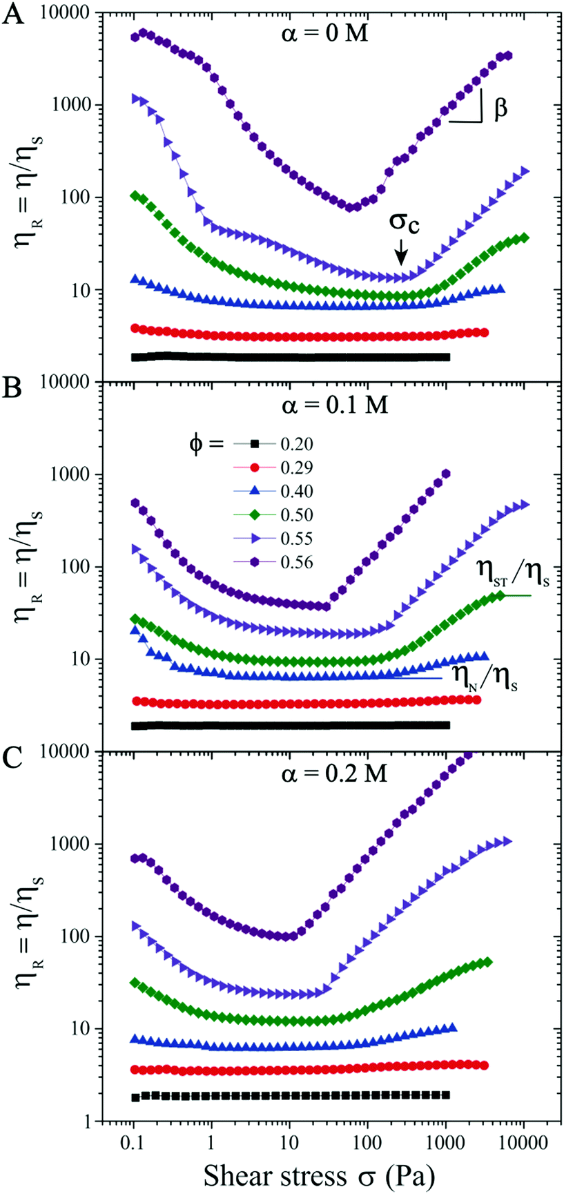 | ||
| Fig. 1 Rheological flow curves of the relative viscosity η/ηs (ηs being the solvent viscosity) versus the shear stress σ for suspensions at different volume fractions (0.20 ≤ ϕ ≤ 0.56) and salt concentrations (α) at (A) 0 M, (B) 0.1 M, and (C) 0.2 M. The pointer in (A) shows the critical stress (σc) for the onset of shear thickening (ST). ηN and ηST are the plateau viscosities before and after the onset of shear thickening, respectively. In the ST regime (σ > σc), η ∝ σβ, where β is the ST exponent. | ||
Increasing the monovalent salt concentration to α > 0.2 M, the attractive contribution becomes more relevant. We next consider a suspension with ϕ = 0.45 and α = 0.3 M. Due to attractive particle interactions, the suspension forms discrete aggregates in equilibrium (see Fig. S2 in the ESI†59) and becomes weakly attractive. The flow curve shows an initial shear thinning behavior with increasing σ, and transitions directly to the shear thickening regime (Fig. 2). Above σc ≈ 10 Pa, the ST exhibits two distinct ST exponents with β = 0.2 (σ > 10 Pa) and 0.1 (σ > 200 Pa), respectively. The reversible flow curve now displays a small hysteresis at σ < 100 Pa (hollow symbols in Fig. 2A) resulting from the dynamical nature of colloidal aggregates. To quantify if this hysteresis behavior is time dependent, we perform creep measurements where a constant σ is applied for 600 s (Fig. 2B). To ensure that the initial conditions are the same for all measurements, we apply a pre-shear stress of ∼ 5.4 Pa (corresponds to the minimum ηR shown in the flow curve) for 100 s. In the shear thickening regime of 30 ≤ σ ≤ 800 Pa, Fig. 2(B) shows that ηR is time independent and increases with increasing σ. However, at σ = 5 Pa and in particular σ = 0.5 Pa (corresponding to the shear thinning regime in the flow curve), some time dependent fluctuations in ηR are observed. This fluctuation is possibly caused by the dynamic aggregation and breakage of particle clusters under the competition between shear forces and interparticle attractive forces. The observed fluctuation could also be partially due to the noise and fluctuation at low shear stress values from stress controlled rheometers.
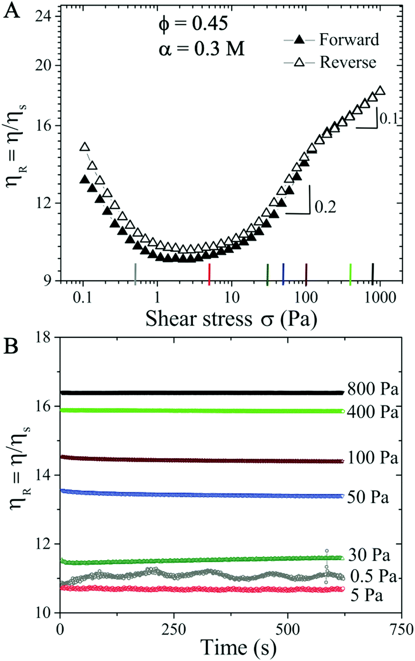 | ||
| Fig. 2 (A) Relative viscosity ηRversus shear stress σ at ϕ = 0.45 and α = 0.3 M. Forward and reverse flow measurements correspond to filled and open symbols, respectively. (B) Temporal behavior of ηR for an applied σ. The colored vertical lines in (A) correspond to the σ values in (B). | ||
3.2 Strongly attractive suspensions
We next consider a suspension with ϕ = 0.46 and α = 0.4 M. At this slightly increased volume fraction and salt concentration the suspension becomes more attractive and the particle aggregates are able to form networks in equilibrium (see Fig. S2 in the ESI†59). The forward flow curve measurement (filled symbols in Fig. 3(A)) exhibits similar behavior to those of ϕ = 0.45 and α = 0.3 M: shear thinning behavior is followed by shear thickening trend with increasing σ, displaying ηR ∝ σβ with three ST exponents of β ∼ 0.23, 0.01, and 0.1 respectively. During the reversible flow curve run, we observe a distinct hysteresis in η with reduced ηR values for σ < 200 Pa, showing two characteristic ST exponents of 0.26 and 0.1.
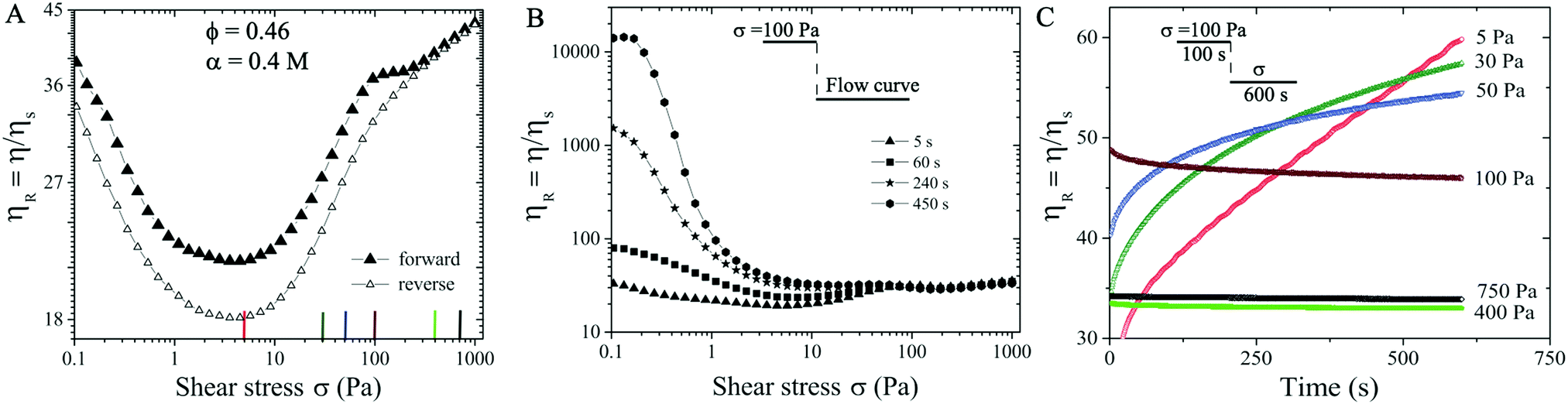 | ||
| Fig. 3 (A) Relative viscosity ηRversus shear stress σ at ϕ = 0.46 and α = 0.4 M, each σ value is applied for 5 s waiting time. (B) Stress controlled forward flow curves of ηRversus shear stress σ with different waiting time being held at an applied σ. (C) Temporal behavior of ηR of σ values of 5–750 Pa. The colored vertical lines shown in (A) correspond to the σ values in (C). Insets in B and C display the flow protocol where samples are pre-sheared at 100 Pa for certain amount of time, followed by forward flow curve or the temporal measurements. | ||
We now investigate whether the ST behavior is time dependent at ϕ = 0.46 and α = 0.4 M. During the forward flow curve measurement, we hold different waiting times (5 s, 60 s, 240 s, and 450 s) at each applied σ value. The relative viscosity ηR displays dramatic difference for different waiting times at σ < 75 Pa, likely caused by the shear induced aggregation kinetics. In particular, the flow procedure with the longest waiting time (filled circles in Fig. 3B) leads to the highest ηR and the strongest shear thinning behavior in the low σ < 75 Pa regime. However, a near constant value of ηR = 46 is observed at σ > 75 Pa, independent of the waiting times (see Fig. 3B). Note that the shear thickening behavior shown in Fig. 3(B) is based on the waiting time of 5 s protocol indicated in Section 2.2.
To verify this temporal behavior, we further perform creep measurements. To ensure the initial conditions being the same for all measurements, we have applied a pre-shear stress of ∼ 100 Pa for 100 s. This pre-shear stress value is selected since ηR values are independent of waiting times at 100 Pa (see Fig. 3(B)). Next, a constant shear stress at different values (5–750 Pa) is applied for roughly 600 s. In contrast to the case at smaller α (i.e., Fig. 2(B)), the creep measurements here show that ηR increases with time and does not reach a steady state in 600 s for σ < 100 Pa. At higher σ (i.e., 400 Pa and 750 Pa), smaller steady state values of ηR ∼ 34 are obtained, likely corresponding to the shear enhanced particle alignment under high shear stresses (Fig. 3(C)).
After pre-shearing the suspension at 100 Pa for 100 s, we apply σ = 1 Pa and observe that ηR continues to increase and never reaches a saturation value even after 6000 s (see Fig. 4A), indicating that the particle network grows over time, a signature of thixotropic yield stress behavior. To further confirm the value of the yield stress σy, in a new measurement, after pre-shearing the suspension at 100 Pa for 100 s, we decrease σ incrementally from 100 Pa, 50 Pa, 30 Pa, 20 Pa, 10 Pa, to 5 Pa. For each applied σ, a minimum strain is imposed to ensure that the suspension reaches steady state.62 We find that ηR reaches a steady state after 4000 s and fluctuates around a mean value of ηR ∼ 3400 at σ = 5 Pa (see Fig. 4B). We further decrease σ from 5 Pa to 1 Pa and observe that ηR diverges over time (Fig. 4(C)), shear rate → 0, implying that no flow is possible in the suspension at σ = 1 Pa, verifying that the suspension exhibits a yield stress value σy = 1 Pa. This also implies that the particles form a connected network and behave like a solid at σ ≤ 1 Pa.
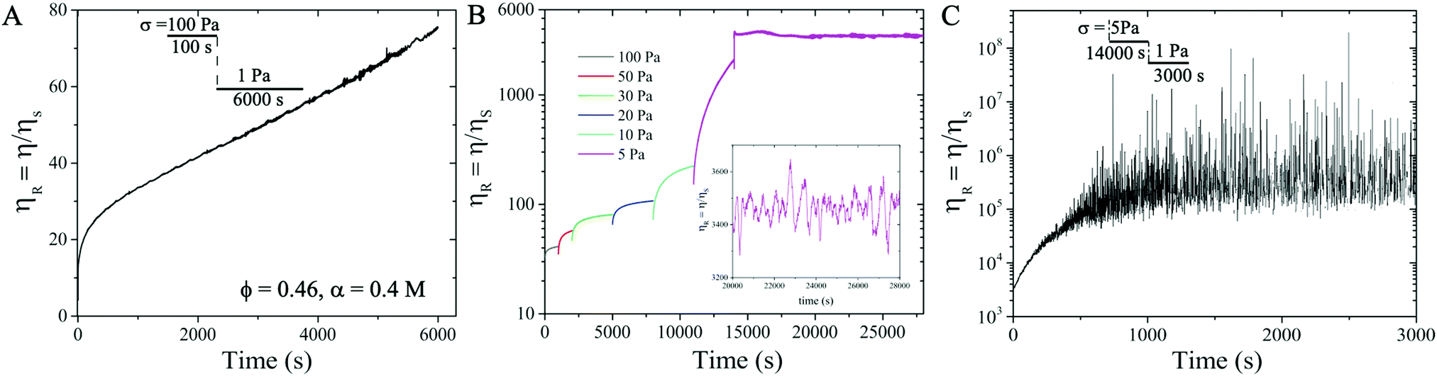 | ||
| Fig. 4 Temporal evolution of ηR with time for attractive suspension at ϕ = 0.46 and α = 0.4 M: (A) σ = 1 Pa applied immediately after the suspension is pre-sheared at 100 Pa for 100 s; (B) σ applied at small increments from 50 Pa, 30 Pa, 20, 10 Pa to 5 Pa with waiting time ranging from 300 to 2000 s to reach a steady state, after the suspension is pre-sheared at 100 Pa for 100 s; (C) σ = 1 Pa applied immediately after the flow measurement shown in (B). Insets in A and C illustrate the flow procedure. Inset in B shows the mean value of ηR ∼ 3400 at σ = 5 Pa. | ||
We perform frequency sweep measurements at fixed strain amplitude of 1% on the suspension immediately after the forward flow curve measurements where σ is increased from 0.1 to 1000 Pa (after the pre-shear protocol) (Fig. 5A), or right after the suspension reaching the yielding conditions at σ = 1 Pa (Fig. 5B). Fig. 5A shows that the elastic modulus G′ is smaller than the viscous modulus G′′ during the frequency sweep, which implies that the network of particles is completely destroyed at high σ. However, after gradually decreasing the σ from 100 Pa to 1 Pa in the suspension (as shown in Fig. 4B and C), the subsequent frequency sweep measurements show that G′ > G′′, implying the elastic nature of the connected network of particles in the attractive suspensions (see Fig. 5B).
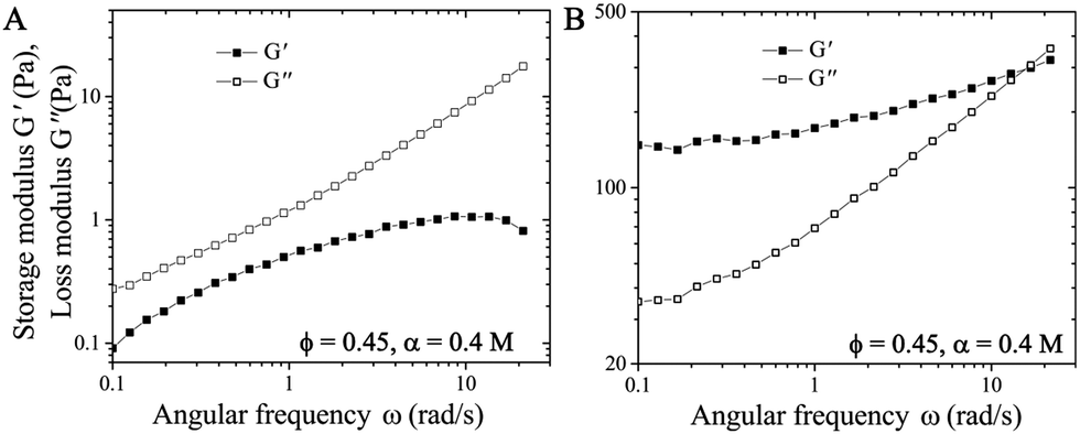 | ||
| Fig. 5 Storage modulus (G′) and loss modulus (G′′) versus the angular frequency (ω) from the frequency sweep measurements performed (A) immediately after the forward flow curve measurements where σ is increased from 0.1 to 1000 Pa, (B) after shearing the suspension at σy = 1 Pa. The strain amplitude is fixed at 1%. | ||
3.3 Time-dependent behavior and Mason numbers
The hysteresis and thixotropic yield stress behavior observed in the flow curve measurements for the strongly attractive suspension system (ϕ = 0.46 and α = 0.4 M), can be interpreted using the Mason number, defined as the ratio of the competing shear and electrochemical forces in sheared suspensions,63–65 Mn = Fshear/Felectrochemical, where Fshear = 6πσa2 is the Stokes drag experienced by a single particle suspended in the shear flow and Felectrochemical is the sum of van der Waals attractive force FvdW = Aa/12h2 (with A the Hamaker constant, a the radius of the particles, h the inter-particles distance), and electrostatic repulsive force given by Frepulsive = 2πεaζ2κexp(−κh), with κ the inverse of the screening length,18ε the permittivity and ζ the measured zeta potential.
The Mason number Mn has been used in literature to capture the particle cluster size and breakup dynamics during flow, and ηR decreases with the reduction of the cluster size in the sheared suspensions. For yield stress fluids, the intermolecular forces can also be estimated as 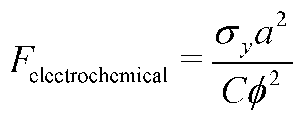 , where C is a proportionality constant related to the bond breaking and yielding condition of the particle aggregates.63–66 The proportionality constant C can be estimated when the gradient dV/dh reaches the maximum, with V the DLVO pair potential of the suspension. In our work, C ∼ 0.01 if we assume the inter-particle separation to be 0.1 nm, the interaction potential energy to be 50 kT, with Mn = 0.06πϕ2σ/σy.36,41,63–68 For example, σ = 5 Pa corresponds to Mn = 0.2 and σy = 1 Pa corresponds to Mn = 0.04.
Fig. 6 shows how the relative viscosity ηR varies with increasing Mason number Mn under both transient (open symbols) and steady state (filled symbols) flow curve measurements corresponding to Fig. 4B. For Mn < 0.1, electrochemical forces Felectrochemical are dominant over shear forces Fshear so that attractive particle networks can be sustained.33,63,64 At 0.1 < Mn < 1.0, shear forces overcome attractive forces to break up the network into aggregates: the aggregate size decreases with increasing Mn, and the sheared suspension exhibits shear thinning behavior.66 In the steady state, at σ = 5 Pa, corresponding to Mn = 0.2, even though the particle network breaks up under applied σ (Fig. 6, close inverted triangles), the competition between the breakage and formation of the particle aggregates can lead to fluctuations in ηR ∼ 3400 (Fig. 4B). At Mn > 1, the network is broken into even smaller aggregates and individual particles, and ηR reduces further, with transient and steady flow curves overlapping each other.
 | ||
| Fig. 6 Relative viscosity (ηR) versus the Mason number (Mn) at ϕ = 0.46 and α = 0.4 M from the flow curve measurements. Open circles represent the data obtained from the transient flow curve with the waiting time 450 s while the filled triangles represent the steady flow curve obtained with the waiting time 2000 s. | ||
3.4 Simulation
To provide insights into the particle–particle and the particle-flow interactions in the suspension and understand its dynamical behavior observed during flow curve measurements, we have performed numerical simulations for the cases of ϕ = 0.46 at α = 0 and 0.4 M. Firstly, we set up the parameters characterising the computational domain. We consider a slightly bidispersed suspension to avoid crystallization effects11 (with the ratio of the radii and volumes of the two dispersed phases, a2/a1 = 1.09 and V2/V1 = 1, respectively), with a total number of particles fixed at N = 512, similar to Mari et al.11 The selected total number of particles N and volume fraction ϕ set the size of the cubic domain, L/a1 = 17.376. We then fix the values of the non-dimensional groups described in Section 2.3 to satisfy the constraints of inertialess, quasi-rigid particles and to span the shear-rates required by the experimental flow-curve. Note that the simulations are performed by applying different values of shear-rates that match the shear stress values imposed experimentally. The screening length value at different salt concentrations is denoted based on the measured experimental data. The ratio between the magnitudes of the repulsive and attractive forces (defining the electrochemical contribution) is adjusted to replicate the increasing salt concentration α in the experiments. The numerical parameters are listed in Table 1., the friction coefficient μC, the non-dimensional shear-rate imposed /0, the ratio of the two screening lengths λs/a1, and the ratio between the repulsive and attractive forces FR/FA considered to mimic the effect of the salt concentration. In particular, for λs/a1 and FR/FA, the numbers in the bracket correspond to salt concentration α = 0 M (far left) and α = 0.4 M (far right). Note that for the non-dimensional groups, we have chosen the radius of the particles of the smallest phase as the reference radius
| N | L/a1 | a 2/a1 | V 2/V1 | St |
|
μ C |
/0 |
λ s/a1 | F R/FA |
|---|---|---|---|---|---|---|---|---|---|
| 512 | 17.376 | 1.09 | 1 | 10−3 | 4 × 10⁵ | 0.5 | {10−5,…,10} | [0.0225,0.0065] | [19,1] |
Fig. 7 shows very good agreement of the relative viscosity ηR obtained from the simulation (symbols) and experimental results (solid curves). Note that the experimental value of ηR is lower than the simulated value at low σ ∼ 0.1 Pa, likely due to the noise and fluctuation at low shear stress values for stress controlled rheometers (Fig. 4).
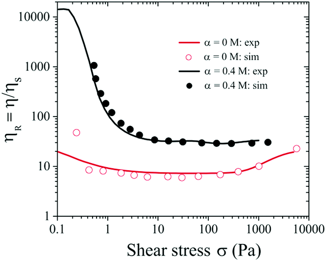 | ||
| Fig. 7 Relative viscosity (ηR) versus σ for ϕ = 0.46 and α = 0 and 0.4 M. Symbols represent numerical data at α = 0 and 0.4 M respectively, and solid lines represent experimental data. | ||
We also examine the temporal dependence of the rheological properties of the highly attractive suspension considered (ϕ = 0.46 and α = 0.4 M) to understand its hysteresis behavior. We first analyze the time-evolution of the relative viscosity contributions at different shear stress σ applied to the suspension. In particular, we consider the suspensions with applied σ = 0.2, 2, 10 and 100 Pa. Since the experimental measurements were obtained after an initial pre-shearing of the suspensions with σ = 100 Pa, an initial condition that mimics such pre-shearing has been applied to all the cases analysed. Fig. 9 illustrates the temporal evolution of ηR at different σ, highlighting contributions from the electrochemical (attractive and repulsive together) and contact forces related to the tangential friction11,58 in the dense suspension. In particular, a strong time-dependence of ηR is observed at low values of σ close to σy (see σ = 0.2 Pa, Fig. 9A). In this regime, the suspension needs very long time to adjust and reach the equilibrium condition. This is due to the continuous competition between electro-repulsive and attractive forces (red curve) that dominate the behavior of the suspension. The second contribution comes from the particle–particle contacts (green curve) which can be neglected at this low shear stress regime. This trend is consistent with the experimental observations shown in Fig. 3B with the 450 s waiting time.
When σ is increased beyond the yield stress, ηR (black curve) decreases (Fig. 7) and the waiting time required to reach the steady state reduces drastically. In this regime, the relative contributions from the electro-chemical forces (red curve) and the particle–particle contacts (green curve) exchange their roles, with the latter becoming increasingly important in relative terms of ηR, and the competition between the repulsive and attractive contributions weakens, making the suspension more stable (Fig. 8B–D).
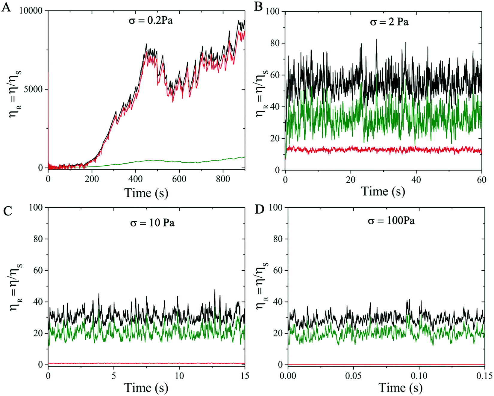 | ||
| Fig. 8 Simulation results of temporal evolution of relative viscosity ηR (black) with its contributions broken down to electro-chemical (i.e., the sum of the repulsive and attractive contributions, red), contact (green) and hydrodynamics (not shown) forces, under applied stress σ = (A) 0.2 Pa, (B) 2 Pa, (C) 10 Pa and (D) 100 Pa. | ||
 | ||
| Fig. 9 Simulation results of the average size distribution of particle clusters at different shear stress values (σ = (A) 0.2 Pa, (B) 2 Pa, (C) 10 Pa, (D) 100 Pa) for strongly attractive suspension of α = 0.4 M and ϕ = 0.46. Orange and blue bars represent the transient and converged states, respectively. The total number of particles in the simulation is 512. | ||
Next, we compute the average size distribution of the particle clusters formed when the suspensions reach steady state and during the transient state, by sampling 100 snapshots over a short time window. Fig. 9 shows the distributions of particle clusters at the stationary (blue histogram) and the transient (orange histogram) state. In particular, we observe that at low σ = 0.2 Pa (Fig. 9A) the distribution of the typical cluster size in the transient regime is more fragmented, prompting the unstable behavior of the suspension due to the continuous competition between the repulsive and attractive forces that break and create aggregates of particles, respectively. At higher σ, where the suspension reaches the equilibrium state quickly and the competition between repulsive and attractive forces is almost absent, the transient and the converged distribution of the cluster size are comparable and no significant difference is observed (Fig. 9B–D).
A visual image of the clusters of particles obtained at low shear stress σ = 0.2 Pa is shown in Fig. 10, where panel A shows the maxi-cluster of particles formed when the steady state is reached and panel B shows the fragmentation effect during the transient state.
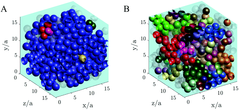 | ||
| Fig. 10 Snapshots of the particle networks represented by different solid colors in the strongly attractive suspension (α = 0.4 M and ϕ = 0.46) when the shear stress σ = 0.2 Pa is applied to the suspension. The minimum network size, N, considered as a valid cluster in this plot is N ≥ 2. The transparent particles are individual particles that do not form a cluster. (A) Steady state and (B) transient state. The axis x/a, y/a and z/a represent the streamwise, shearwise and spanwise direction, respectively, with a the radius of the smallest particle. | ||
We are aware of the limitation on the maximum cluster size introduced by the number of particles used (N = 512), however the analysis carried out in this work is used mainly for qualitative confirmation and to provide an explanation of the experimental results.
3.5 First normal stress difference
To clarify the role of hydrodynamic and frictional contact forces in our sheared dense suspension systems, we plot the first normal stress difference N1 against the applied shear stress σ from experimental rheometry data. It has been shown in the literature that negative N1 is caused by dominant hydrodynamic forces while positive N1 is due to the dominant frictional contact forces19. Note that the attractive forces in the suspension also contribute to negative N1 values.For stable colloidal particles (i.e., α = 0 M and 0.29 ≤ ϕ ≤ 0.56), Fig. 11A shows that N1 becomes negative at σ > 600 Pa, which is well above σc ∼ 300 Pa shown in Fig. 1A. The particle contacts mediated by hydrodynamic or frictional forces need to be sufficiently large to induce the sign change of N1.19 At ϕ = 0.56 where discontinuous shear thickening (DST) is observed, N1 first turns negative with increasing σ, but abruptly changes to a positive value at σ ∼ 1900 Pa (see Fig. 11A), indicating that the frictional contact force becomes dominant in the DST regime for repulsive dense suspensions. This observation is similar to those reported for ST spherical colloidal particles by Royer et al.19
 | ||
Fig. 11 (A) First normal stress difference (N1) for volume fractions 0.29 ≤ ϕ ≤ 0.56 at α = 0 M. (B) N1 for 0 ≤ α ≤ 0.5 M at ϕ = 0.46. (C) The critical shear stress (σc) plotted against α for 0.29 ≤ ϕ ≤ 0.56: the squares are the experimental values while the open circles are calculated by  , where Frepulsive = 2πεε0aζ2κexp(−κh). The error bars correspond to variations in σc from multiple flow curves measurements on the same sample. , where Frepulsive = 2πεε0aζ2κexp(−κh). The error bars correspond to variations in σc from multiple flow curves measurements on the same sample. | ||
To illustrate the salt concentration effect, we keep the particle volume fraction ϕ = 0.46 fixed and vary the salt concentration α from 0–0.5 M. Even though the critical stress σc is decreased from 300 Pa to 15 Pa when α increases from 0 M to 0.3 M (Fig. 1B and 11C), the N1versus σ curves follow the same trend for all α (Fig. 11B), with N1 becoming negative when σ > 600 Pa.
We finally evaluate the dependence of σc on α. In the CST region (ϕ < 0.56), σc values do not vary significantly for different ϕ given a fixed α (Fig. 1), so plots in Fig. 11C hold (within errors of 20%) for all volume fractions ϕ. Since particle aggregations at α > 0.3 M change the flow curve behavior significantly, we restrict our attention to σc for α ≤ 0.3 M. Shear thickening was thought to be a shear rate-controlled phenomena in earlier studies and prior attempts have been made to estimate σc or c dependence on the physio-chemical properties of the particles in the suspensions.25,69 Boersma et al. predicted the relationship between the critical shear rate c and the repulsive force in a suspension69 and observed that the critical shear rate decreased with increasing ϕ. Later, Maranzano et al. predicted the critical stress σc based on the hydrodynamics model by changing the pH levels in the suspension to adjust the particle stability. However, their model simply assumed that the interparticle separation distance was smaller than their equilibrium separation distance, and the screening length and the surface potential in their suspension was not controlled. These predictions were based on the assumptions that the particles do not form any surface contacts. However, recent studies show that the colloidal particles can form physical contacts by overcoming electrostatic repulsive forces when σ ≥ σc where σc is determined by Frepulsive. For example, Comtet et al.18 proposed that at the onset of shear thickening, the particle–particle contact force balances the electrostatic repulsive force with  , with x a prefactor dependent on the friction coefficient, particle roughness and shape. Applying this scaling relationship, with the repulsive force calculated as Frepulsive = 2πεaζ2κexp(−κh) in our dense suspensions (0.29 ≤ ϕ ≤ 0.55), the best curve fit to our experimental data yields the prefactor x = 0.025 (open circles in Fig. 11C), showing good agreement between experimental and the scaling relationship. This further implies that the contact forces make important contributions to the shear thickening behavior in our sheared dense suspensions.
3.6 State diagram
We construct a state diagram to summarize both Newtonian and the shear thickening behavior with different volume fractions ϕ and salt concentrations α of sheared suspensions performed in our experiments (see Fig. 12). For α ≤ 0.2 M with all ϕ < 0.56 studied, the suspensions exhibit Newtonian behavior. For higher volume fraction 0.25 < ϕ ≤ 0.56 at α ≤ 0.2 M, the suspension remains stable and exhibits typical shear thickening behavior without hysteresis (CST at ϕ < 0.56 and DST at ϕ = 0.56 respectively). In this regime at α → 0.2 M, even though introducing NaCl in the suspension leads to particle cluster formation, the interaction strength is not sufficient to form percolating contact network. The cluster size does not evolve under shear and remains history independent, therefore no hysteresis is observed. These weakly attractive suspensions do display increased ηR with typical shear thickening behavior, but shear thickening exponents are reduced above σc.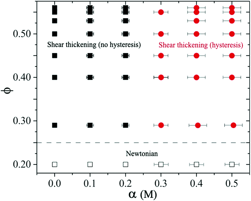 | ||
| Fig. 12 State diagram of sheared dense suspensions of repulsive and attractive spherical silica particles. The dotted line represent the transition from Newtonian to shear thickening behavior. Squares represent shear thickening behavior which is reversible in the full range of applied stresses. Circles represent shear thickening behavior with hysteresis in forward and reverse stress measurements. The error bars correspond to variations in α from multiple experiments. | ||
For 0.25 < ϕ ≤ 0.56 at α > 0.2 M, the attractive force dominates. Large particle clusters form and evolve continuously with increasing shear stress during the flow curve measurements. For moderate attractive force (i.e., ϕ ≥ 0.45 and α = 0.3 M), we observe two shear thickening exponents above σc and small hysteresis in ascending and descending flow curve measurements. For ϕ ≥ 0.45 at even higher salt concentration (i.e., α ≥ 0.4 M), the suspensions can form percolating networks with a measurable yield stress. In this regime, we observe strongly time-dependent behavior of the sheared suspension with large hysteresis.
In equilibrium, the cluster size and structure are determined by competing Brownian and inter-particle forces resulting in fractal-alike particle clusters.61 The size, shape and structure of these clusters change under applied shear stresses (or shear rates).8,31,70,71 For 0.25 < ϕ < 0.56 and α < 0.2 M, particles remain stable and flow curves show reversibility. In the case of moderately stable particles at α = 0.2 M, the interparticle separation in equilibrium remains sufficiently large such that the van der Waals forces do not play any significant role, and thus hysteresis is absent. At higher salt concentrations α > 0.2 M, the repulsive force becomes weaker so that the particle clusters can form which can reorganise under shear. The dynamic nature of the particle clusters causes hysteresis in flow curve measurements. This behavior is illustrated in the state diagram with a dividing line around α → 0.25 M that separates the hysteresis versus the no hysteresis domains in the shear thickening regime (at ϕ > 0.25), see Fig. 12. Note that the interparticle distance decreases significantly as ϕ → ϕj, so the particles can form clusters even when the suspension is moderately stable, i.e., at smaller salt concentrations.
4 Conclusions
In this work, we study the effect of particle stability on shear thickening and its reversibility behavior of dense suspensions of hard spherical silica particles. The stability of the particles is tuned by adding a simple monovalent salt, sodium chloride, with concentrations α ∈ [0,0.5] M. For repulsive and moderately attractive suspensions under shear, shear thinning is followed by shear thickening (without hysteresis) behavior with increasing shear stress. At higher volume fractions and salt concentrations, the suspension becomes more attractive and forms particle clusters and cluster network. The strongly attractive suspension becomes sensitive to flow history below the critical shear stress, due to the dynamic nature of the particle cluster where cluster size and structure depend on the rate of applied stress as well as the entire or immediate history of the shear rate/stress imposed. Shear thickening with significant hysteresis is observed. Using numerical simulations, we find that the hysteresis behavior arises due to the competition among shear, electrostatic repulsive, van der Waals attractive and frictional contact forces. Our experimental results show that critical shear stress decreases with increasing salt concentrations α (i.e., decreasing repulsive interaction) in the shear thickening regimes. This behavior can be estimated by balancing the force required to form particle–particle contact against the electrostatic repulsive force. Combined with numerical simulations, these results imply the formation of particle contacts in our dense suspensions.Conflicts of interest
There are no conflicts to declare.Acknowledgements
All authors gratefully acknowledge the support of Okinawa Institute of Science and Technology Graduate University (OIST) with subsidy funding from the Cabinet Office, Government of Japan. The authors also acknowledge the computational time provided by the Scientific Computing Section of Research Support Division at OIST. A. Q. S. acknowledges funding from the Joint Research Projects (JRPs) supported by JSPS and SNSF. V. R. also acknowledges financial support from the Japanese Society for the Promotion of Science (Grants No. 21K13895).References
- Intermolecular and Surface Forces, ed. J. N. Israelachvili, Academic San Diego, San Diego, 2nd edn, 1992 Search PubMed.
- H. A. Barnes, J. Rheol., 1989, 33, 329–366 CrossRef CAS.
- G. Bossis and J. Brady, J. Chem. Phys., 1989, 91, 1866–1874 CrossRef CAS.
- J. R. Melrose, J. H. V. Vliet and R. C. Ball, Phys. Rev. Lett., 1996, 77, 4660–4663 CrossRef CAS PubMed.
- D. Lootens, H. van Damme, Y. Hémar and P. Hébraud, Phys. Rev. Lett., 2005, 95, 268302 CrossRef.
- A. Fall, F. Bertrand, G. Ovarlez and D. Bonn, J. Rheol., 2012, 56, 575–591 CrossRef CAS.
- N. Wagner and J. Brady, Phys. Today, 2009, 62(10), 27–32 CAS.
- Colloidal Suspension Rheology, ed. J. Mewis and N. J. Wagner, Cambridge University Press, Cambridge, 1st edn, 2012 Search PubMed.
- E. Brown and H. H. Jaeger, J. Rheol., 2012, 56, 875–923 CrossRef CAS.
- R. Seto, R. Mari, J. F. Morris and M. M. Denn, Phys. Rev. Lett., 2013, 111, 098302 CrossRef.
- R. Mari, R. Seto, J. F. Morris and M. M. Denn, J. Rheol., 2014, 58, 1693–1724 CrossRef CAS.
- M. Wyart and M. E. Cates, Phys. Rev. Lett., 2014, 112, 098302 CrossRef CAS.
- R. Mari, R. Seto, J. F. Morris and M. M. Denn, Proc. Natl. Acad. Sci. U. S. A., 2015, 112, 15326–15330 CrossRef CAS.
- A. K. Gurnon and N. J. Wagner, J. Fluid Mech., 2015, 769, 242–276 CrossRef CAS.
- B. M. Guy, M. Hermes and W. C. K. Poon, Phys. Rev. Lett., 2015, 115, 088304 CrossRef CAS PubMed.
- N. Y. C. Lin, B. M. Guy, M. Hermes, C. Ness, J. Sun, W. C. K. Poon and I. Cohen, Phys. Rev. Lett., 2015, 115, 228304 CrossRef.
- A. Fall, N. Huang, F. Bertrand, G. Ovarlez and D. Bonn, Phys. Rev. Lett., 2015, 114, 098301 CrossRef CAS.
- J. Comtet, A. N. Guillaume Chatté, L. Bocquet, A. Siria and A. Colin, Nat. Commun., 2017, 8, 15633–15638 CrossRef CAS.
- J. R. Royer, D. L. Blair and S. D. Hudson, Phys. Rev. Lett., 2016, 116, 188301 CrossRef PubMed.
- V. Rathee, D. L. Blair and J. S. Urbach, Proc. Natl. Acad. Sci. U. S. A., 2017, 114, 8740–8745 CrossRef CAS PubMed.
- C. Clavaud, A. Bŕut, B. Metzger and Y. Forterre, Proc. Natl. Acad. Sci. U. S. A., 2017, 114, 5147–5152 CrossRef CAS.
- B. Saint-Michel, T. Gibaud and S. Manneville, Phys. Rev. X, 2018, 8, 031006 CAS.
- V. Rathee, D. L. Blair and J. S. Urbach, J. Rheol., 2020, 64, 299–308 CrossRef CAS.
- S. Saw, M. Grob, A. Zippelius and C. Heussinger, Phys. Rev. E, 2020, 101, 0120602 CrossRef.
- B. J. Maranzano and N. J. Wagner, J. Rheol., 2001, 45, 1205–1222 CrossRef CAS.
- B. J. Maranzano and N. J. Wagner, J. Chem. Phys., 2001, 114, 10514–10527 CrossRef CAS.
- A. J. Liu and S. R. Nagel, Nature, 1998, 396, 21–22 CrossRef CAS.
- A. Sun and S. Gunasekaran, Int. J. Food Prop., 2009, 12(1), 70–101 CrossRef.
- N. Akafuah, S. Poozesh, A. Salaimeh, G. Patrick, K. Lawler and K. Saito, Coatings, 2016, 6(2), 1–22 CrossRef.
- S. R. Raghavan and S. A. R. Khan, J. Colloid Interface Sci., 1997, 185, 57 CrossRef CAS PubMed.
- D. Bonn, M. M. Denn, L. Berthier and S. M. Thibaut Divoux, Rev. Mod. Phys., 2017, 89, 035005 CrossRef.
- A. Mohraz and M. J. Solomon, J. Rheol., 2005, 49(3), 657–681 CrossRef CAS.
- B. Rajaram and A. Mohraz, Soft Matter, 2010, 6, 2246–2259 RSC.
- P. Moller, A. Fall, V. Chikkadi, D. Derks and D. Bonn, Philos. Trans. R. Soc., A, 2009, 367, 5139–5155 CrossRef PubMed.
- T. Divoux, V. Grenard and S. Manneville, Phys. Rev. Lett., 2013, 110, 018304 CrossRef.
- S. Jamali, R. C. Armstrong and G. H. McKinle, Phys. Rev. Lett., 2019, 123, 248003 CrossRef PubMed.
- A. Boromand, S. Jamali and J. M. Maia, Soft Matter, 2017, 13, 458–473 RSC.
- M. Bouzid and E. D. Gado, Langmuir, 2018, 34, 773–781 CrossRef CAS.
- X. J. Cao, H. Z. Cummins and J. F. Morris, J. Colloid Interface Sci., 2012, 368, 86–96 CrossRef CAS.
- A. Furukawa and H. Tanaka, Phys. Rev. Lett., 2010, 104, 245702 CrossRef PubMed.
- S. Jamali and J. F. Brady, Phys. Rev. Lett., 2019, 123, 138002 CrossRef CAS.
- E. Brown, N. A. Forman, C. S. Orellana, H. Zhang, B. W. Maynor, D. E. Betts, J. M. DeSimone and H. M. Jaeger, Nat. Mater., 2010, 9, 220–224 CrossRef CAS PubMed.
- S. Pedenker, J. Chun and J. F. Morris, Soft Matter, 2017, 9, 220–224 Search PubMed.
- A. Singh, S. Pednekar, J. Chun, M. M. Denn and J. F. Morris, Phys. Rev. Lett., 2019, 122, 098004 CrossRef CAS.
- N. Park, V. Rathee, D. L. Blair and J. C. Conrad, Phys. Rev. Lett., 2019, 122, 228003 CrossRef CAS.
- B. M. Guy, J. A. Richards, D. J. M. Hodgson, E. Blanco and W. C. K. Poon, Phys. Rev. Lett., 2018, 121(12), 128001 CrossRef CAS PubMed.
- J. A. Richards, B. M. Guy, M. H. E. Blanco, G. Poy and W. C. Poon, J. Rheol., 2020, 64(2), 405–412 CrossRef CAS.
- J. A. Richards, R. E. O'Neill and W. C. K. Poon, Rheol. Acta, 2021, 60(2), 97–106 CrossRef CAS.
- D. B. Genovese, Adv. Colloid Interface Sci., 2012, 171, 1–16 CrossRef PubMed.
- V. Gopalakrishnan and C. F. Zukoski, J. Rheol., 2004, 48, 1321 CrossRef CAS.
- W. Stöber, A. Fink and E. Bohn, J. Colloid Interface Sci., 1968, 26(1), 62–69 CrossRef.
- L. Zhang, M. D'Acunzi, M. Kappl, G. K. Auernhammer and D. Vollmer, Langmuir, 2009, 25, 711–2717 Search PubMed.
- R. C. Ball and J. R. Melrose, Phys. A, 1997, 247(1–4), 444–472 CrossRef CAS.
- S. Luding, Granular Matter, 2008, 10(4), 235 CrossRef.
- É. Guazzelli and J. F. Morris, A physical introduction to suspension dynamics, Cambridge University Press, 2011, vol. 45 Search PubMed.
- R. D. Groot and P. B. Warren, J. Chem. Phys., 1997, 107(11), 4423–4435 CrossRef CAS.
- A. W. Lees and S. F. Edwards, J. Phys. C: Solid State Phys., 1972, 5(15), 1921 CrossRef.
- A. Monti, V. Rathee, A. Q. Shen and M. E. Rosti, 2021, arXiv preprint, arXiv:2108.01013.
- ESI,† Link to be inserted.
- C. Heussinger, Phys. Rev. E: Stat., Nonlinear, Soft Matter Phys., 2013, 88, 050201 CrossRef PubMed.
- R. Hidalgo-Alvarez, A. Martln, A. Fernandez, D. Bastos, F. Martinez and F. de las Nieves, Adv. Colloid Interface Sci., 1996, 67, 1–118 CrossRef CAS.
- D. C.-H. Cheng, J. Chem. Phys., 1986, 25, 542–554 CAS.
- A. P. R. Eberle, N. Martys, L. Porcar, S. R. Kline, W. L. George, J. M. Kim, P. D. Butler and N. J. Wagner, Phys. Rev. E: Stat., Nonlinear, Soft Matter Phys., 2014, 89, 050302 CrossRef PubMed.
- J. M. Kim, A. P. R. Eberle, A. K. Gurnon, L. Porcar and N. J. Wagner, J. Rheol., 2014, 58, 1301–1328 CrossRef.
- J. B. Hipp, J. J. Richards and N. J. Wagner, J. Rheol., 2021, 65, 145–157 CrossRef CAS.
- Z. Varga and J. W. Swan, J. Rheol., 2018, 62, 405–418 CrossRef CAS.
- N. Koumakisa and G. Petekidis, Soft Matter, 2011, 7, 2456–2470 RSC.
- N. Koumakis, E. Moghimi, R. Besseling, W. C. K. Poon, J. F. Brady and G. Petekidis, Soft Matter, 2015, 11, 4640–4648 RSC.
- W. H. Boersma, J. Laven and H. N. Stein, AIChE J., 1990, 36(3), 321–332 CrossRef CAS.
- Colloidal Dispersion, ed. W. Russel, D. A. Saville and W. R. Schowalter, Cambridge University Press, Cambridge, 1989 Search PubMed.
- J. Mewis and N. J. Wagner, Adv. Colloid Interface Sci., 2009, 147–227, 214 CrossRef PubMed.
Footnote |
| † Electronic supplementary information (ESI) available. See DOI: 10.1039/d1sm00971k |
| This journal is © The Royal Society of Chemistry 2021 |