 Open Access Article
Creative Commons Attribution 3.0 Unported Licence
Electric-field-induced deformation, yielding, and crumpling of jammed particle shells formed on non-spherical Pickering droplets†
K.
Khobaib
 a,
A.
Mikkelsen
 a,
T.
Vincent-Dospital
 b and
Z.
Rozynek
 *ab
*ab
aFaculty of Physics, Adam Mickiewicz University, Uniwersytetu Poznańskiego 2, 61-614 Poznań, Poland. E-mail: zbiroz@amu.edu.pl
bPoreLab, The Njord Centre, Department of Physics, University of Oslo, Blindern, N-0316 Oslo, Norway
First published on 21st April 2021
Abstract
Droplets covered with densely packed solid particles, often called Pickering droplets, are used in a variety of fundamental studies and practical applications. For many applications, it is essential to understand the mechanics of such particle-laden droplets subjected to external stresses. Several research groups have studied theoretically and experimentally the deformation, relaxation, rotation, and stability of Pickering droplets. Most of the research concerns spherical Pickering droplets. However, little is known about non-spherical Pickering droplets with arrested particle shells subjected to compressive stress. The experimental results presented here contribute to filling this gap in research. We deform arrested non-spherical Pickering droplets by subjecting them to electric fields, and study the effect of droplet geometry and size, as well as particle size and electric field strength, on the deformation and yielding of arrested non-spherical Pickering droplets. We explain why a more aspherical droplet and/or a droplet covered with a shell made of larger particles required higher electric stress to deform and yield. We also show that an armored droplet can absorb the electric stress differently (i.e., through either in-plane or out-of-plane particle rearrangements) depending on the strength of the applied electric field. Furthermore, we demonstrate that particle shells may fail through various crumpling instabilities, including ridge formation, folding, and wrinkling, as well as inward indentation.
1 Introduction
Particles of nano- and micrometer size can strongly adhere to droplet interfaces,1 forming a particle shell that changes the mechanical properties of the fluid droplet interface.2–4 Droplets densely covered with particles (referred to as Pickering droplets) constitute Pickering emulsions and Pickering emulsion gels,5–7 and can be used to produce particle capsules.8–10 Such emulsions and capsules are promising for many applications, particularly in the pharmaceutical and food industries,11–13 as well as in the oil industry and biofuel processing.14,15 Moreover, particle-covered droplets facilitate the fabrication of new materials16–18 and can be designed to form novel adaptive structures.19,20 Pickering droplets can also be used in basic research, e.g., as model systems for mimicking the physical properties of red blood cells21 or for studying particle crystal growth and ordering or particle layer buckling on curved interfaces.22–26In many research areas, knowledge of the stability and mechanics of an individual Pickering droplet is essential, e.g., for the efficient fabrication of Pickering emulsions,27 for designing emulsions with controlled stability,28,29 and, in general, for the further development of the abovementioned research fields. Several research groups have studied theoretically and experimentally the deformation,30–34 relaxation,35,36 and mechanical properties of Pickering droplets.37,38 Most of the research concerns spherical droplets. Yet several studies exist on non-spherical Pickering droplets, investigating the droplets’ fabrication,38–41 deformation, kinetic, relaxation, and rheological properties.42–45 However, little is known about arrested non-spherical particle shells subjected to stress. The experimental results presented here contribute to filling this gap in research. The objective of this study is thus to understand and describe the behavior of non-spherical Pickering droplets with jammed particle shells under stress.
We use an electric field (E-field) to induce a compressive electric stress on a Pickering droplet and study both qualitatively and quantitatively the droplet's respond to the E-field. The questions of principal interest in this research were the following: (i) How does particle shell geometry affect the critical E-field strength required for arrested Pickering droplets to collapse? (ii) How do particle and droplet size affect the collapsing mechanism of non-spherical Pickering droplets? (iii) How does the E-field strength affect the wrinkling and crumpling of particle shells? To answer these questions, we performed experiments on mm-size silicone oil droplets coated with electrically insulating polymeric microparticles suspended in castor oil and subjected to direct current (DC) E-fields.
Various E-field approaches have been demonstrated to be useful in investigating the deformation,34,46 electrorotation,32 propulsion,47 and buckling45 of Pickering droplets. Here, we use a static and uniform E-field to generate compressive stress via charge accumulation on the droplet's surface. Under a DC E-field, free charges (impurities in the oils) accumulate at the oil–oil interface. Depending on the electrical properties of the oils and particles, the Pickering droplet may acquire a dipole moment oriented either parallel or antiparallel with the E-field. In our experiments, we prepared Pickering droplets with an electrical conductivity smaller than that of the surrounding castor oil. The charge relaxation time (τ = εε0/σ, where ε is the relative dielectric permittivity, ε0 is the vacuum permittivity, and σ is the electric conductivity) of castor oil is shorter than that of silicone oil, so the droplet acquires a dipole moment oriented antiparallel with the E-field. As a result, compressive stress is exerted on the Pickering droplet (see Fig. 1a), whose magnitude is controlled by the strength of the E-field. We used this compressive mode to study the mechanical properties of the particle shells.
2 Materials and methods
2.1. Materials
The particle-covered droplets used in our experiments were made of silicone oil (Rhodorsil Oils 47, with electrical conductivity σin ∼ 10 pS m−1, relative permittivity εin ∼ 2.8, density ρin ∼ 0.96 g cm−3 at 25 °C, and viscosity ∼50 mPa s at 25 °C) and polyethylene (PE) particles with diameters between around 2 and 100 μm (Cospheric LLC, with electrical conductivity σpe < 1 × 10⁻¹⁵ S m−1, relative permittivity εpe ∼ 2.3, and density ρpe ∼ 1.0 g cm−3). Depending on particle size and the desired volume and shape of the droplets, the concentration of particles was between 8% and 12% by weight (see ref. 27 for the formula for obtaining densely packed spherical shells). Castor oil (Sigma-Aldrich 83![[thin space (1/6-em)]](https://www.rsc.org/images/entities/char_2009.gif) 912, with electrical conductivity σex ∼ 100 pS m−1, relative permittivity εex ∼ 4.7, density ρex ∼ 0.96 g cm−3, and viscosity ∼ 750 mPa s at 25 °C) was used as an external fluid. Castor oil and silicone oil are immiscible, and the interfacial tension between them is ∼4.5 mN m−1.
912, with electrical conductivity σex ∼ 100 pS m−1, relative permittivity εex ∼ 4.7, density ρex ∼ 0.96 g cm−3, and viscosity ∼ 750 mPa s at 25 °C) was used as an external fluid. Castor oil and silicone oil are immiscible, and the interfacial tension between them is ∼4.5 mN m−1.
2.2. Experimental set-up
The experimental set-up consisted of a signal generator (SDG1025, SIGLENT Technologies Co, Ltd, China), a voltage amplifier (20HVA24-BP1, HVP High Voltage Products GmbH, Germany), a digital microscope (AM7315MZT, Dino-Lite, AnMo Electronics Corporation, Taiwan), a light source (KL 300 LED, Schott AG, Germany), a computer for collecting images and recording videos, and a sample cell (an optical glass cuvette of 15 mm × 15 mm × 30 mm) with two inserted copper plates that acted as electrodes. The sample cell was placed on a mechanical XYZ translation stage (LT3, Thorlabs, Sweden) to ease its positioning relative to the optical path of the microscope. The observation view of the microscope was always perpendicular to the E-field (which in all figures is in the horizontal direction). A schematic figure illustrating the experimental set-up is shown in Fig. 1b.2.3. Formation of a non-spherical Pickering droplet
Castor oil was poured into a sample cell. Silicone oil and particles were measured by weight and then stirred together to make a dispersion. To form a dispersion droplet in the castor oil, we used a mechanical pipette. When a silicone oil droplet with particles was formed in the castor oil, most of the particles resided inside the droplet. To bring the particles to the droplet's interface, we used an E-field, as demonstrated in ref. 2 and 8. As soon as a particle reached the interface, it was transported toward the electric equator of the droplet by the convective motion of liquids (i.e., induced electrohydrodynamic flows).48,49 Particles at the equator formed a densely packed particle film that widened as time passed and more particles reached the interface (typically taking a few minutes). The final particle packing and the coverage of the droplet's interface depended on the applied E-field and the particle concentration. Extensive details of the method can be found in our previous studies.19,50To make a stable non-spherical droplet with a jammed particle shell, we coalesced two spherical droplets that were initially almost fully covered with particles, as shown in Fig. S1 and Movie S1 (ESI†). To further tune the shape of the arrested Pickering droplet, we electrorotated it at an elevated DC E-field (between 500 and 800 V mm−1). As the Pickering droplet rotated, it also stretched, allowing unjamming of the shell particles. By turning off the E-field, the droplet relaxed and reduced the area of its interface, thereby again inducing particle jamming and the formation of a shell. However, the structure of the shell was now more disordered and porous compared with the structure of the initial shell (see also ref. 51). We found that when the droplet was further stretched (by applying stronger E-fields), the particle shell that formed after switching off the E-field was more elongated and more porous. Finally, as a droplet with a new shape was formed, we used an AC E-field (e.g., 100 Hz, 300 V mm−1) to align it with its major axis along the direction of the E-field. In the AC E-field, the droplet acquires a dipole moment oriented parallel with the E-field, so the droplet is stretched. Whenever it was necessary to make the droplet more ellipsoidal and symmetric, we further increased the strength of the AC E-field up to 1 kV mm−1. In Movie S2 (ESI†), we provide an example of the electrorotation of a droplet in a DC E-field and an example of the aligning and shaping of a droplet in an AC E-field.
2.4. Image processing and estimation of the local curvature
Images taken in the experiment on the prolate-to-oblate shape transition of particle-covered droplets subjected to different E-field strengths (presented in Section 3.4) were processed using MATLAB® software and its Image Processing Toolbox™. On each image, the shape of the droplet (2D-projected onto our camera's focal plane) was first detected from the luminance contrast between the droplet and the background oil by using an automatic boundary tracing algorithm. We applied a running-average smoothing filter to the derived shapes to attenuate the sharp edges arising from the discrete representation of the droplets (i.e., due to the camera's pixel size). With a least-square method,52 we then inverted the circle equations that best fitted the various local portions of the obtained periphery of the droplet. We thus computed the local curvature along the droplet's shape as the inverse of the fitted circle's radius. For the MATLAB® code, see the ESI.†3 Results
3.1. E-Field-induced deformation and yielding
An arrested Pickering droplet made of silicone oil and 30 μm polyethylene (PE) particles was prepared in castor oil. The droplet was non-spherical with a deformation of ∼0.2 (left inset image in Fig. 2). Deformation is defined as D = (d‖ − d⊥)/(d‖ + d⊥), where d‖ and d⊥ are the lengths of the droplet's axes parallel and perpendicular to the direction of the E-field, respectively. The application of an E-field resulted in the generation of compressive stress on the droplet. In weak E-fields (less than 200 V mm−1), we observed no change in the droplet's shape. However, in stronger E-fields, the droplet deformed and eventually yielded, which led to a prolate-to-oblate deformation transition.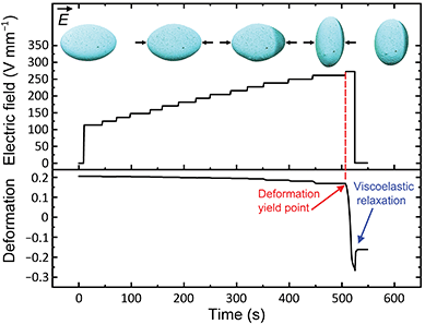 | ||
| Fig. 2 E-Field-induced deformation of an arrested droplet with a jammed particle shell. Dynamic deformation of an arrested Pickering droplet made of silicone oil covered with 30 μm PE particles. Initially, the major and minor axes of the droplet were 3.9 and 2.6 mm, respectively (left inset image). The Pickering droplet was suspended in castor oil and subjected to a DC E-field that was stepwise increased. In the inserted images, the direction of the E-field was horizontal, and the arrows schematically indicate the compressive electric forces. See also corresponding Movie S3 (ESI†). | ||
The quantitative data are presented in Fig. 2, in which we plot the measured values of the droplet's deformation versus time and the strength of the applied E-field. As the E-field was stepwise increased from 0 to 225 V mm−1, the magnitude of the droplet's deformation was mostly unchanged (ΔD ∼ 0.01). The elastic stress from the particle layer was sufficiently strong to withstand the electric stress, and the prolate shape of the droplet was undisturbed. At moderate E-field strengths (between 225 and 265 V mm−1), we observed small changes in the droplet's deformation (ΔD ∼ 0.03). This deformation was caused by the rearrangement of particles; that is, the packing of the particles increased, and/or the particles deformed out-of-plane. At E ∼ 272 V mm−1, the droplet went through a prolate-to-oblate deformation transition. This E-field threshold is referred to as the critical yield point of the droplet, Ey. The droplet yielded when the total magnitudes of the applied electric stress and the capillary stress (originating from the surface tension between the liquids) were sufficiently large to overcome the mechanical resistance of the particle layer. This experiment demonstrates that the particle layer of an arrested Pickering droplet subjected to compressive electric stress resembles a Bingham plastic material. That is, it behaves like a solid material at low applied stresses and becomes liquid-like when the applied stress exceeds a yield stress point.
We noted that shortly before turning off the E-field (∼520 s in Fig. 2), the droplet was compressed to such an extent that the particle layer unjammed. Nevertheless, as soon as the E-field was switched off, the droplet relaxed (D changed by ∼0.1), causing the particles to jam again; hence the main part of the oblate deformation remained. The inset images in Fig. 2 show how the arrested Pickering droplet was compressed from a prolate shape into an oblate geometry (see also Movie S3, ESI†). The arrows schematically indicate the direction of the electric forces that acted on the droplet.
The evolution of the Pickering droplet's deformation can also be studied with a test in which the droplet is subjected to an E-field of constant strength for a long time, rather than to an E-field that is stepwise increased. Such a bifurcation measurement requires more time and effort than the experiment presented above. However, it may provide more precise estimates of the values of the yield point and enables studying the deformation dynamics.
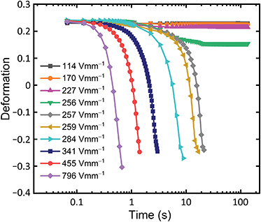
In Fig. 3, we present the results of a bifurcation experiment performed on a non-spherical PE particle-covered droplet studied at different E-field strengths (114–796 V mm−1). At each E-field strength, the data were collected for up to two minutes. We re-shaped the droplet (see the procedure described in Section 2.3) before each experiment to obtain the same initial non-spherical geometry; that is, the minor axis is 2.5 mm and the major axis is 4.0 mm. In lower E-fields (up to 256 V mm−1), the droplet's deformation was small, and the droplet reached a stable prolate state (shown in Fig. 3). This occurred because the applied electric stress was not strong enough to overcome the elastic energy of the particle shell, and the droplet stayed in a prolate shape. When the droplet was subjected to stronger E-fields; that is, E ≥ Ey = 257 V mm−1, it deformed continuously from a prolate into an oblate shape.
We found that above the critical E-field strength, the prolate-to-oblate deformation transition time varied with the applied E-field strength. For example, at E = 257 V mm−1, the transition took several seconds, whereas at E = 796 V mm−1 it took less than a second. While performing this experiment, we also observed that depending on the strength of the applied E-field, the electric stress was absorbed differently by the Pickering droplet (through in-plane or out-of-plane particle rearrangements). We investigate and discuss this observation in Section 3.4.
The value of the yield point obtained from the bifurcation test (257 V mm−1) differs slightly from the value estimated from the first experiment in which the E-field strength was stepwise increased (272 V mm−1). The difference may arise from applying different methodologies since in the experiment presented in Fig. 2, we changed the E-field strength in steps of ∼15 V mm−1. It can also result from a difference in the initial geometry of the studied Pickering droplets (the initial droplet in the experiment presented in Fig. 3 was more elongated than the one shown in Fig. 2). We therefore decided to study the influence of the droplet's initial geometry on the deformation and yielding of a non-spherical Pickering droplet.
3.2. Effect of initial droplet geometry on deformation and yielding
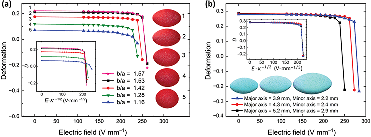
We prepared five Pickering droplets with the same volume (within an error of less than 3%) but different shapes and subjected them to E-fields between 0 and 260 V mm−1. Except for particle size (now 50 μm), the other parameters, such as particle material and oil type, were the same as in the experiments described in the previous section. Fig. 4a presents the deformation values plotted against the applied E-field strength for the Pickering droplets with different initial shapes (shown in the inset images of Fig. 4a). The results show that the more elongated Pickering droplets (with larger asphericity) yielded at higher E-field strengths. We here assumed that the droplets had an axisymmetric shape and that they were initially ellipsoidal. Thus, the asphericity (its degree) of the initial shape of a droplet can be defined by the local curvature at the droplet's electric pole, κ = b/a2, where a and b are the minor and major semi-axes of an ellipsoid. In the inset of Fig. 4a, we normalized the data by dividing the argument values by . All the data, except the values for the droplet that was initially the least deformed, collapsed into one master curve, indicating that
  . The data points marked with up-pointing blue triangles (droplet no. 5) lay outside the master curve because this nearly spherical droplet began electrorotating at E > 200 V mm−1 (this phenomenon is explained in detail in ref. 51). As a result, a stronger E-field was required to compressively deform the droplet.
The droplets in Fig. 4a had different prolate asphericities but also different aspect ratios b/a. To exclude the role of the aspect ratio in the droplet's deformation and yielding (and to present the curvature dependence), we performed an additional set of experiments. We used three Pickering droplets of different volumes (10–23 mm3) but with the same aspect ratio b/a ∼ 1.8 (see images in Fig. 4b). The droplets were subjected to E-fields of different strengths (increased stepwise). Again, we found that the value of Ey was higher for the particle shells with larger curvature values (see Fig. 4b). For example, the largest droplet yielded at E ∼ 250 V mm−1, while the smallest droplet yielded at E ∼ 284 V mm−1. In the inset of Fig. 4b, we plot D versus Eκ−1/2, and the collapsed data indicate that  .
.
3.3. Influence of particle size on deformation and yielding
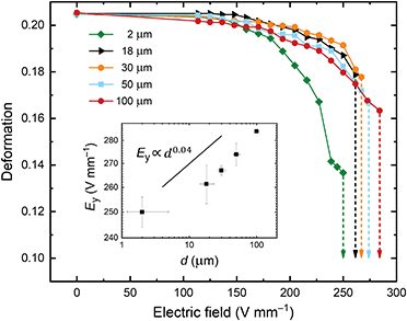
In the next experiment, we study the effect of particle size on the mechanical properties of particle shells. We prepared non-spherical Pickering droplets covered with PE particles of sizes ranging from 2 to 100 μm. The initial shapes of all the droplets were similar, and they had similar volumes (within an error of less than 3%). The droplets were subjected to DC E-fields ranging from 0 to 285 V mm−1. We found that the critical E-field for yielding (i.e., deforming a droplet into an oblate shape) depended on the size of the particles on the droplet's interface (Fig. 5). For example, for a particle shell composed of 2 μm PE particles, the critical E-field was around ∼250 V mm−1, whereas for a particle shell composed of 100 μm PE particles, the critical E-field was ∼285 V mm−1. We found that the critical E-field scaled as Ey ∝ d0.04 (see inset plot in Fig. 5) for a Pickering droplet that was initially ellipsoidal with an aspect ratio b/a ∼ 1.5.Unlike elastic membranes on droplets/bubbles, shells made of particles can undergo structural changes; that is, the particles can change positions relative to their neighbours. This, in turn, helps to accommodate the applied stresses. In Movie S4 (ESI†), we demonstrate, with a few examples, how particles rearrange in-plane, enabling the droplet to change its shape.
Particle shells on curved interfaces may also deform by buckling through ridges, folds, or wrinkles.53–55 As we will show in the next section, the rate of compression will determine the buckling mode. In the experiment of which the results are shown in Fig. 5, we observed the formation of several bumps with small amplitudes. These bumps, observed typically at Ey/2 < E < Ey, were formed near the electric equator of the droplet. Their localization is not very symmetric, which could be the effect of the geometrical disorder in the particle shell. We note that the particles used in the experiments were slightly polydispersed. Thus, a geometrical disorder of particle positions perpendicular to the mean plane of the monolayer is expected. These geometrical deviations may contribute to the deformation of the particle shell by the mechanisms of the particle overlapping and disentanglement.56 These phenomena may cause local out-of-plane deformations that result in the densification of the monolayer and a reduction in the surface area occupied by the particles. This, in turn, enables shape changes of a Pickering droplet.
In general, we observed less in-plane particle motion for bigger particles (≥50 μm) than for smaller particles. Qualitatively, the behaviour of shells composed of bigger particles resembles that of a granular arch. Pitois et al.56 studied the collapsing of armoured bubbles and droplets by deflation. They observed a transition in particle shell deformation depending on the ratio of particle size to droplet size. Like us, they found that droplets covered with small particles were easier to deform than those covered with larger particles.
Structured interfaces can also absorb compressive stress by the expulsion of material into one of the liquid phases.57 We did not observe this process in the system studied here. The microparticles used in our experiments were rather large and therefore strongly bound to the silicone oil−castor oil interface (with a binding energy ≈104kBT),55 thus preventing particle expulsion.
3.4. Absorption of electric stress by the particle shell
As noted in Section 3.1, we observed that a Pickering droplet absorbed the electric stress differently depending on the strength of the applied E-field. To investigate this phenomenon further, we performed additional experiments to study the influence of both the compression dynamics and the particle size on the wrinkling of particle shells. The Pickering droplets used in the experiments were covered with PE particles of sizes ranging from 2 to 100 μm. The droplets had similar volumes and initial shapes. They were suspended in castor oil and subjected to E-fields of strengths 350, 700, and 1050 V mm−1. Under these E-fields, the droplets continuously deformed from prolate into oblate shapes. When the weakest E-field (with a strength of 350 V mm−1) was applied, the particle shells deformed slowly. The droplets deformed from a prolate into an oblate shape without an observable formation of wrinkles at their particle shells or irregular folds with small amplitudes (see Fig. 6a and Fig. S2, ESI†).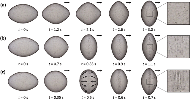 | ||
| Fig. 6 Deformation of particle shells at different E-field strengths. Arrested droplets with PE particle shells composed of 2 μm PE particles. Initially, at t = 0 s, the particle shells were ellipsoidal, with a major axis of ∼3.9 mm and a minor axis of ∼2.6 mm. The particle-coated droplets were subjected to E-fields of strengths (a) 350, (b) 700, and (c) 1050 V mm−1 applied in the horizontal direction, as indicated by the arrows. In these E-fields, the droplets continuously deformed from prolate into oblate shapes. See also corresponding Movie S5 (ESI†). | ||
Slow compression of particle shells facilitate in-plane particle rearrangements analogous to the gliding of grain layers in granular flows.58 In response to the compressive electric stress, the surface particles started to move relative to one another. We observed several slip lines appearing during shell compression. A similar phenomenon was observed and presented in ref. 37. Note that in stronger E-fields of 700 and 1050 V mm−1, the particle shells deformed considerably faster (see Fig. 6b and c). Consequently, the particles did not have sufficient time to rearrange and thus deformed out-of-plane, forming more regular wrinkles. The wrinkles were formed perpendicular to the applied electric field, as the particle layer was compressed in the direction from the electric poles to the electric equator, as indicated by the arrows in Fig. 6c.
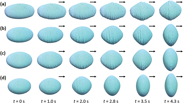
At the strongest E-field strength (1050 V mm−1), we observed wrinkling of particle shells on all droplets (see Fig. 7 and corresponding Movie S6, ESI†). The wrinkling pattern can be quantified in terms of the wrinkling wavelength. Because the wrinkling wavelength is sensitive to the strain,59 it had to be measured in such a way that we could compare the results of the droplets coated with particles of different sizes (which have a different deformations at different times). We decided to measure the wavelength of the wrinkles that were formed close to the electric equator of a droplet, at the time when the droplet was slightly oblate (see the droplets marked with the dashed rectangle in Fig. 7a–d), that is, when the wrinkles could be clearly observed. In Fig. 7e, we plot the wavelength values (λ) against the particle diameter d. We found that the wrinkling wavelength scaled roughly as  . Similar scaling behaviour was reported by researchers who studied wrinkling of particle monolayers formed on either flat liquid–air interfaces60,61 or liquid–liquid interfaces.55
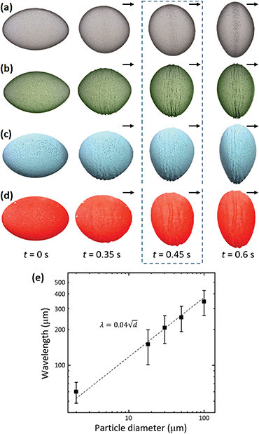 | ||
| Fig. 7 Wrinkling of particle shells. Four droplets covered with PE particles of different diameters, (a) 2 μm, (b) 18 μm, (c) 30 μm, and (d) 50 μm, were subjected to an E-field of strength 1050 V mm−1 applied in the horizontal direction, as indicated by the arrows. Initially, at t = 0 s, the particle shells were ellipsoidal, with a major axis of ∼3.9 mm and a minor axis of ∼2.6 mm. (e) A log–log plot of the measured crumpling wavelength of the deformed particle shells as a function of the particle size. See also Movie S6 (ESI†). | ||
We fitted the data with the square root power function (dashed line in Fig. 7e) to compare our results with the results of other studies. We found that the wavelengths of the wrinkles (λ = 0.04d0.5) were shorter than those reported for particle layers on flat interfaces. For example, λv = 0.24d0.49 and λj = 0.25d0.5 were reported by Vela et al.61 and Jambon et al.,60 respectively. The shorter wavelengths observed for our particle shells are due to the curvature of the interface. Any deformation on a curved interface yields an additional strain contribution that increases the elastic energy of the particle layer, which in turn gives rise to shorter wavelengths. The wavelengths observed here are also shorter than those reported in our previous studies on particle shells formed on mm-sized droplets (λ = 0.07d0.5).55 This difference in wavelength is to be expected because a particle shell is strained more by compressive stress than by hoop stress, as demonstrated in ref. 55.
While performing the experiments on the Pickering droplets’ prolate-to-oblate transition at various strengths of the E-field, another feature caught our interest. Depending on the compression dynamics (i.e., the E-field strength), the particle-covered droplets underwent different shape transformations at the intermediate stages of the transition. In Fig. 8a, we present images of the experiment on Pickering droplets made of 2 μm particles (shown in Fig. 6). This time, we chose the frames of the recorded videos in such way that we could compare the droplets' shapes at similar stages of the prolate-to-oblate transition. Using the MATLAB software suite (see ESI† for the MATLAB code), we estimated the curvature values along the droplets' edges. The automatically detected droplets’ contours, together with the calculated color-coded values of the curvature, were added to the experimental images.
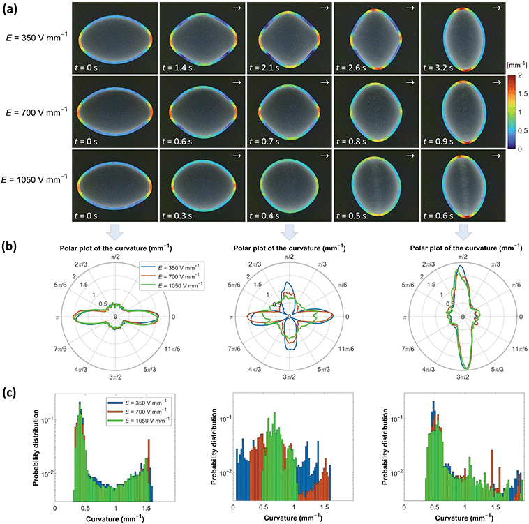 | ||
| Fig. 8 Deformation of particle shells at different E-field strengths. Arrested droplets with particle shells made of 2 μm PE particles. The droplets were subjected to E-fields of strengths 350–1050 V mm−1 applied in the horizontal direction, as indicated by the arrows. (a) Series of experimental images with added color-coded contours representing the values of the curvature (in mm−1). The same color scale applies to all the images. (b) The estimated curvature values plotted against the 2D polar angle. (c) The curvature distributions are presented using bar charts. See also corresponding Movie S7 (ESI†). | ||
The difference between the droplets’ projected two-dimensional (2D) shapes is clearly seen in the middle column of Fig. 8a. The contour of the Pickering droplet subjected to the weakest E-field resembles a rhombus shape, whereas that of the Pickering droplet subjected to the strongest E-field is nearly spherical. A similar tendency was also observed for droplets covered by larger particles of 18–50 μm (see Fig. S3, ESI†).
We further computed the data to present the curvature distributions at different stages. The results are displayed using polar plots to properly appreciate the variations in curvature values along the polar angle (Fig. 8b) and bar plots to show the probability distribution (Fig. 8c). For the sake of image clarity, we show the data only at three characteristic times: before the application of the E-field, in the middle of the prolate-to-oblate transition, and just before the E-field was turned off. For the full analysis, see corresponding Movie S7 (ESI†).
The polar plots presented in Fig. 8b reveal how the curvature varies as a function of the direction. As expected, the maximum values of the curvatures of all three initial droplets (before the application of an E-field) align with the first principal curvature direction (see left panel in Fig. 8b). From the histogram shown on the left panel of Fig. 8c, we learn that the probability distribution of the curvature values is bimodal for all three droplets, with the major mode located at ∼0.4 mm−1.
After the E-field was applied, the Pickering droplets acquired distinctively different shapes. In the middle of the transition, the curvature variation along the polar angle is very different for the three Pickering droplets. The droplet that was compressed slowly (at E = 350 V mm−1) developed a nearly bicone shape (a similar shape can also be observed when two liquid marbles coalesce via collision).62 The contour drawn around the droplet's 2D projection resembled a square, with maximum curvatures aligning in both principal polar directions and nearly flat regions in the ordinal directions. On the other hand, the Pickering droplet that was compressed very fast (subjected to E = 1050 V mm−1) acquired an almost spherical shape. The contour drawn around that droplet's projection is almost a circle, and the curvature values are similar in all directions (see the middle panel of Fig. 8b, green line). Consequently, the probability distribution of the curvature also differs for each droplet. The distribution is almost uniform for the droplet subjected to the weakest E-field, whereas the histogram for the droplet subjected to the strongest E-field approaches a Dirac distribution centred at ∼0.7 mm−1. Eventually, all the droplets obtained a similar oblate shape, and the data for the three droplets overlap again (see the right panels of Fig. 8b and c).
As already discussed, the slow compression of the particle shells enables in-plane particle rearrangements (possibly leading to a higher particle packing). This process costs less energy than the out-of-plane particle shell deformation and is therefore more favourable. Thus, in weak E-fields (just above Ey), the particle-coated droplet obtains a bicone-like shape when transiting from a prolate into an oblate geometry. By contrast, the higher compression speeds (for a stronger E-field) allowed a deformation with minimal time-dependent behaviour of the particles. The electric stress acting on the non-spherical Pickering droplets was absorbed mainly by the buckling of the particle shell buckling, as the particles had not enough time to rearrange themselves on the droplet's surface.
Let us now investigate, with a new set of experiments, how the initial shape of a Pickering droplet affects the morphologies of the wrinkles. We prepared Pickering droplets of equal volumes (within an error of less than 3%) but with different geometries (see the images in the left column of Fig. 9). The Pickering droplets were then subjected to an E ∼ 320 V mm−1. We found that more elongated droplets deformed slower into an oblate shape than less elongated droplets (with time measured from the application of the E-field to the moment that the droplet obtains an oblate geometry). In Fig. 3, we show that the prolate-to-oblate deformation time decreased when the difference E − Ey increased, where E is the applied E-field strength and Ey is the E-field threshold at which the droplet yields. From the results shown in Fig. 4a, we also observed that more elongated droplets (of the same volume) yielded at higher E-field strengths owing to differences in rigidity stemming from differences in curvature. The difference E − Ey is thus smaller for the more elongated droplets, explaining why they deform slower than more spherically shaped droplets (compare Fig. 9a and d).
During the deformation transition from a prolate into an oblate shape, the droplet's surface area (A) changed; it decreased in the first phase and then increased. The change in surface area (ΔA) was greater for Pickering droplets that were initially more elongated than for droplets that were initially more spherical. Thus, the particle shells formed on the elongated droplets crumpled, with many clear folds with large amplitudes (Fig. 9a and b), to accommodate this large change in surface area during the shape transition. The shells formed on less elongated droplets (Fig. 9c and d) formed rather irregular and less apparent folds and ridges. In general, the buckled structures are not very symmetric, which we believe is the effect of the geometrical disorder in the particle shell.
3.5. Deformation of asymmetric shells formed on droplets
In Sections 3.2 and 3.3, we studied the effect of the initial droplet geometry and particle size on the deformation and yielding of a Pickering droplet. We concluded that a more aspheric droplet and/or a droplet covered with a shell made of larger particles required higher electric stress (i.e., a stronger E-field) to deform and yield than a droplet that is more spherical and/or covered with a shell made of smaller particles. Here, we study asymmetric Pickering droplets with a homogeneous shell (composed of one particle type) and a heterogeneous shell (consisting of two parts with different particle types).In the first case, we prepared an asymmetric Pickering droplet with a homogeneous shell by coalescing two droplets of different sizes (∼1.6 and 2.7 mm). One part of the shell was more curved than the other part (see Fig. 10a). Subjected to an E-field of 300 V mm−1, the particle shell folded at the right part of the shell. This result is consistent with our experimental data presented in Section 3.2 since the shell yielded at the less curved side of the particle shell.
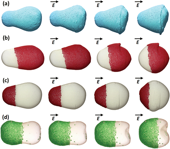 | ||
| Fig. 10 Asymmetric Pickering droplets subjected to electric stress. (a) A homogeneous shell was made of blue 30 μm PE particles. (b–d) Heterogeneous particle shells were composed of (b) white 2 μm PE particles and red 50 μm PE particles, (c) red 50 μm PE particles and white 2 μm PE particles, and (d) green 100 μm PE particles and white 2 μm PE particles. The Pickering droplets were subjected to an E-field of 300 V mm−1. The particle shells deformed through (a–c) one main fold or via (d) inward indentation. The direction of the E-field was horizontal, as indicated by the arrows. During compression, a vertical inward fold was formed at the right part of the heterogeneous shells. See Movie S8 (ESI†) for a video of the deformation dynamics. | ||
We also prepared three Pickering droplets with a heterogeneous shell. The shells were composed of white 2 μm PE particles and red 50 μm PE particles (Fig. 10b), red 50 μm PE particles and white 2 μm PE particles (Fig. 10c), and green 100 μm PE particles and white 2 μm PE particles (Fig. 10d). The droplets were slightly rounder on one side (the right side of the images in Fig. 10b and c). We designed one droplet with bigger particles on the more spherical part of the shell (Fig. 10b), while for the other droplet, the bigger particles were on the most aspherical part of the shell (Fig. 10c). The Pickering droplets were subjected to an E-field of 300 V mm−1 (above the critical E-field for yielding). At this E-field strength, the particle layer on both Pickering droplets folded at the more spherical part of the shell, regardless of whether this part of the shell was composed of smaller or larger particles. The result indicates that the difference in mechanical properties of the shell (frictional and/or elastic), as determined by particle size, is too small to be dominating. Thus, for such asymmetrically shaped Pickering droplets, the geometry of the particle shell (i.e., its curvature) prevails over the mechanical properties of the particle shell.
In Fig. 10a–c, the particle shells deformed through one main fold. However, the droplet's deformation may also proceed through inward indentation. In Fig. 10d, we show the deformation of an aspherical peanut-like shell. Initially, before the application of the electric stress, the right part of the shell was flat. Subjected to an E-field, this flat part bent inward forming a concave cup-like shape. In the system studied here, the electric stress acts on the entire shell, with its magnitude distributed unevenly along the polar angle. However, the strongest force (in the normal direction to the shell surface) acts on the droplet's electric pole. Thus, it can be assumed (with some approximation) that the experiment with the electric field resembles the indentation tests of ellipsoidal shells.63,64 For a capsule with a thin shell (fulfilling the requirement th/r ≪ 1, where r is the radius and th is the thickness), the axial stiffness of the shell scales proportionally to the curvature κ. As the shell is nearly flat on the right side of the arrested droplet, κ → 0, and the electric stress near the electric pole is balanced only by capillary forces and the pressure difference across the droplet's interface, whereas there is a nearly zero contribution from the elasticity of the particle shell. This explains why the right part of the shell bent inward.
4 Conclusions
In a three-phase system consisting of silicone oil, castor oil, and electrically insulating particles, the application of a DC E-field resulted in the generation of stress acting compressively on a Pickering droplet. We used such an E-field to study the deformation, yielding, and crumpling of non-spherical particle shells formed on droplets. Our experimental results show that both the initial geometry and the size of the droplets, as well as the size of the particles, influence the deformation and yielding of non-spherical Pickering droplets. For example, a more aspheric droplet and/or a droplet covered with larger particles required higher electric stress (i.e., a stronger E-field) to yield and to deform from a prolate into an oblate geometry. We also investigated the crumpling of particle shells and observed that a Pickering droplet absorbed the electric stress differently depending on the strength of the applied E-field. That is, slow compression of particle shells facilitated in-plane particle rearrangements that promoted the formation of ridges, whereas fast compression resulted in the formation of wrinkles on the particle shells. Interestingly, the Pickering droplets acquired distinctively different shapes when transiting from prolate into oblate geometries depending on the compression speed. Many studies have been devoted to the characterization of the rheological properties of particle-coated droplets (and flat particle-coated interfaces). However, most experiments are limited to slow deformations. Our results contribute to a better understanding of the dynamic deformation of particle-laden interfaces with curvature.We also found that particle shells formed on more elongated droplets crumpled with many clear folds with large amplitudes, as compared with shells formed on less elongated droplets. Moreover, the wrinkling wavelength of the particle monolayer also depended on the particle diameter, and it scaled as  , meaning that a particle shell composed of bigger particles wrinkles at a higher wavelength. This confirms again that wrinkling phenomena show universal scaling behavior, as proposed by Cerda and Mahadevan in their article on the physics of wrinkling.65 Finally, we studied the absorption of electric stress by asymmetric Pickering droplets. We found that particle shells can deform either through folding or through inward indentation.
Given the limited knowledge of the mechanics of non-spherical Pickering droplets probed by E-fields, we hope to have provided an entry point for further theoretical and experimental studies. Future experimental studies should investigate how particle properties, such as electrical conductivity, dielectric permittivity, cohesiveness, particle packing, and particle disorder, affect the stability and mechanics of Pickering droplets subjected to E-fields. It would also be interesting to study the particle rearrangements in detail (e.g., by microstructure characterization using microscope images of a zoomed-in region) during the deformation of the particle shells. This would surely help to better understand the microstructural mechanisms underlying particle shell deformation (similar to studies on arrested coalescence of Pickering emulsion droplets).42 This research can also be extended to investigations of the effect of the morphology of droplet stabilizers, such as different particle shapes66 and particle mixtures (as in experiments with liquid marbles),67 on the viscoelastic properties of arrested Pickering droplets with jammed particle shells.
Author contributions
Z. Rozynek and A. Mikkelsen initiated the project and performed preliminary experiments. K. Khobaib performed all the actual experiments of which the results are presented in Fig. 2–10. T. Vincent-Dospital contributed to the curvature data presentation (Fig. 8 and Fig. S3, ESI†). K. Khobaib wrote the first version of the manuscript. All authors took part in discussions that helped finalize the manuscript.Funding sources
This work was supported by the Polish National Science Centre through the OPUS (2015/19/B/ST3/03055) and PRELUDIUM (2019/35/N/ST5/02821) programs. A. Mikkelsen received funding from the European Union's Horizon 2020 Research and Innovation Programme under Marie Skłodowska-Curie Grant Agreement No. 752896. We also thank the Research Council of Norway for its support through the Centres of Excellence Funding Scheme, Project No. 262644.Conflicts of interest
There are no conflicts of interest to declare.References
- B. P. Binks, Curr. Opin. Colloid Interface Sci., 2002, 7, 21–41 CrossRef CAS.
- A. Mikkelsen, P. Dommersnes, Z. Rozynek, A. Gholamipour-Shirazi, M. D. S. Carvalho and J. O. Fossum, Materials, 2017, 10, 436 CrossRef.
- A. D. Dinsmore, M. F. Hsu, M. G. Nikolaides, M. Marquez, A. R. Bausch and D. A. Weitz, Science, 2002, 298, 1006–1009 CrossRef CAS PubMed.
- C. Zeng, H. Bissig and A. D. Dinsmore, Solid State Commun., 2006, 139, 547–556 CrossRef CAS.
- Y. Yang, Z. Fang, X. Chen, W. Zhang, Y. Xie, Y. Chen, Z. Liu and W. Yuan, Front. Pharmacol., 2017, 8, 287 CrossRef PubMed.
- R. Aveyard, B. P. Binks and J. H. Clint, Adv. Colloid Interface Sci., 2003, 100–102, 503–546 CrossRef CAS.
- M. N. Lee, H. K. Chan and A. Mohraz, Langmuir, 2012, 28, 3085–3091 CrossRef CAS PubMed.
- Z. Rozynek, A. Mikkelsen, P. Dommersnes and J. O. Fossum, Nat. Commun., 2014, 5, 3945 CrossRef CAS PubMed.
- T. Bollhorst, K. Rezwan and M. Maas, Chem. Soc. Rev., 2017, 46, 2091–2126 RSC.
- A. M. Bago Rodriguez and B. P. Binks, Curr. Opin. Colloid Interface Sci., 2019, 44, 107–129 CrossRef CAS.
- T. Kubiak, J. Banaszak, A. Józefczak and Z. Rozynek, ACS Appl. Mater. Interfaces, 2020, 12, 15810–15822 CrossRef CAS PubMed.
- Q. Sun, Y. Du, E. A. H. Hall, D. Luo, G. B. Sukhorukov and A. F. Routh, Soft Matter, 2018, 14, 2594–2603 RSC.
- E. M. Shchukina, M. Graham, Z. Zheng and D. G. Shchukin, Chem. Soc. Rev., 2018, 47, 4156–4175 RSC.
- B. L. Peng, L. C. Zhang, J. H. Luo, P. M. Wang, B. Ding, M. X. Zeng and Z. D. Cheng, RSC Adv., 2017, 7, 32246–32254 RSC.
- C. Herrera, D. Fuentealba, I. T. Ghampson, C. Sepulveda, J. L. García-Fierro, R. I. Canales and N. Escalona, Catal. Commun., 2020, 144, 106092 CrossRef CAS.
- L. Wei, S. Yan, H. Wang and H. Yang, NPG Asia Mater., 2018, 10, 899–911 CrossRef CAS.
- J. Guo, B. L. Tardy, A. J. Christofferson, Y. Dai, J. J. Richardson, W. Zhu, M. Hu, Y. Ju, J. Cui, R. R. Dagastine, I. Yarovsky and F. Caruso, Nat. Nanotechnol., 2016, 11, 1105–1111 CrossRef CAS.
- V. O. Ikem, A. Menner and A. Bismarck, Langmuir, 2010, 26, 8836–8841 CrossRef CAS PubMed.
- P. Dommersnes, Z. Rozynek, A. Mikkelsen, R. Castberg, K. Kjerstad, K. Hersvik and J. Otto Fossum, Nat. Commun., 2013, 4, 2066 CrossRef PubMed.
- Z. Rozynek, K. Khobaib and A. Mikkelsen, ACS Appl. Mater. Interfaces, 2019, 11, 22840–22850 CrossRef CAS PubMed.
- V. Kozlovskaya, J. F. Alexander, Y. Wang, T. Kuncewicz, X. Liu, B. Godin and E. Kharlampieva, ACS Nano, 2014, 8, 5725–5737 CrossRef CAS PubMed.
- W. T. Irvine, V. Vitelli and P. M. Chaikin, Nature, 2010, 468, 947–951 CrossRef CAS PubMed.
- V. N. Manoharan, Science, 2015, 349, 1253751 CrossRef PubMed.
- C. J. Burke, B. L. Mbanga, Z. Wei, P. T. Spicer and T. J. Atherton, Soft Matter, 2015, 11, 5872–5882 RSC.
- F. Sicard and A. Striolo, Nanoscale, 2017, 9, 8567–8572 RSC.
- J. Hegemann, S. Knoche, S. Egger, M. Kott, S. Demand, A. Unverfehrt, H. Rehage and J. Kierfeld, J. Colloid Interface Sci., 2018, 513, 549–565 CrossRef CAS PubMed.
- Z. Rozynek, R. Bielas and A. Józefczak, Soft Matter, 2018, 14, 5140–5149 RSC.
- C. P. Whitby and E. J. Wanless, Materials, 2016, 9, 626 CrossRef PubMed.
- K. Hwang, P. Singh and N. Aubry, Electrophoresis, 2010, 31, 850–859 CrossRef CAS PubMed.
- J. K. Ferri, P. Carl, N. Gorevski, T. P. Russell, Q. Wang, A. Boker and A. Fery, Soft Matter, 2008, 4, 2259–2266 RSC.
- M. K. Mulligan and J. P. Rothstein, Langmuir, 2011, 27, 9760–9768 CrossRef CAS PubMed.
- M. Ouriemi and P. M. Vlahovska, Langmuir, 2015, 31, 6298–6305 CrossRef CAS PubMed.
- C. Gu and L. Botto, Soft Matter, 2016, 12, 705–716 RSC.
- A. Mikkelsen, Z. Rozynek, K. Khobaib, P. Dommersnes and J. O. Fossum, Colloids Surf., A, 2017, 532, 252–256 CrossRef CAS.
- L. Becu and L. Benyahia, Langmuir, 2009, 25, 6678–6682 CrossRef CAS PubMed.
- A. B. Pawar, M. Caggioni, R. Ergun, R. W. Hartel and P. T. Spicer, Soft Matter, 2011, 7, 7710–7716 RSC.
- A. Mikkelsen, P. Dommersnes and J. O. Fossum, Rev. Cubana Fis., 2016, 33, 47–49 Search PubMed.
- M. M. Cui, T. Emrick and T. P. Russell, Science, 2013, 342, 460–463 CrossRef CAS PubMed.
- S. A. F. Bon, S. D. Mookhoek, P. J. Colver, H. R. Fischer and S. van der Zwaag, Eur. Polym. J., 2007, 43, 4839–4842 CrossRef CAS.
- P. Dahiya, M. Caggioni and P. T. Spicer, Philos. Trans. R. Soc., A, 2016, 374, 20150132 CrossRef PubMed.
- P. Dahiya, A. DeBenedictis, T. J. Atherton, M. Caggioni, S. W. Prescott, R. W. Hartel and P. T. Spicer, Soft Matter, 2017, 13, 2686–2697 RSC.
- Z. Y. Xie, C. J. Burke, B. Mbanga, P. T. Spicer and T. J. Atherton, Soft Matter, 2019, 15, 9587–9596 RSC.
- M. Kaganyuk and A. Mohraz, Soft Matter, 2017, 13, 2513–2522 RSC.
- C. Hao, Z. Xie, T. J. Atherton and P. T. Spicer, Langmuir, 2018, 34, 12379–12386 CrossRef CAS PubMed.
- R. B. Karyappa, S. D. Deshmukh and R. M. Thaokar, Phys. Fluids, 2014, 26, 122108 CrossRef.
- A. Mikkelsen, K. Khobaib, F. K. Eriksen, K. J. Måløy and Z. Rozynek, Soft Matter, 2018, 14, 5442–5451 RSC.
- P. Dommersnes, A. Mikkelsen and J. O. Fossum, Eur. Phys. J.: Spec. Top., 2016, 225, 699–706 CAS.
- G. I. Taylor, A. D. McEwan and L. N. J. D. Jong, Philos. Trans. R. Soc., A, 1997, 291, 159–166 Search PubMed.
- D. A. Saville, Annu. Rev. Fluid Mech., 1997, 29, 27–64 CrossRef.
- Z. Rozynek, P. Dommersnes, A. Mikkelsen, L. Michels and J. O. Fossum, Eur. Phys. J.: Spec. Top., 2014, 223, 1859–1867 CAS.
- Z. Rozynek, J. Banaszak, A. Mikkelsen, K. Khobaib and A. Magdziarz, Soft Matter, 2021 10.1039/D1SM00122A.
- I. Kåsa, IEEE Trans. Instrum. Meas., 1976, IM-25, 8–14 Search PubMed.
- C. Gu and L. Botto, Soft Matter, 2018, 14, 711–724 RSC.
- M. Ouriemi and P. M. Vlahovska, J. Fluid Mech., 2014, 751, 106–120 CrossRef CAS.
- A. Mikkelsen and Z. Rozynek, ACS Appl. Mater. Interfaces, 2019, 11, 29396–29407 CrossRef CAS.
- O. Pitois, M. Buisson and X. Chateau, Eur. Phys. J. E: Soft Matter Biol. Phys., 2015, 38, 48 CrossRef PubMed.
- V. Garbin, Curr. Opin. Colloid Interface Sci., 2019, 39, 202–211 CrossRef CAS.
- T. G. Drake, J. Geophys. Res., 1990, 95, 8681–8696 CrossRef.
- H. Jiang, D.-Y. Khang, J. Song, Y. Sun, Y. Huang and J. A. Rogers, Proc. Natl. Acad. Sci. U. S. A., 2007, 104, 15607–15612 CrossRef CAS PubMed.
- E. Jambon-Puillet, C. Josserand and S. Protière, Phys. Rev. Mater., 2017, 1, 042601 CrossRef.
- D. Vella, P. Aussillous and L. Mahadevan, Europhys. Lett., 2004, 68, 212–218 CrossRef CAS.
- J. Jin, C. H. Ooi, D. V. Dao and N. T. Nguyen, Soft Matter, 2018, 14, 4160–4168 RSC.
- A. Lazarus, H. C. Florijn and P. M. Reis, Phys. Rev. Lett., 2012, 109, 144301 CrossRef CAS PubMed.
- D. Vella, A. Ajdari, A. Vaziri and A. Boudaoud, Phys. Rev. Lett., 2012, 109, 144302 CrossRef PubMed.
- E. Cerda and L. Mahadevan, Phys. Rev. Lett., 2003, 90, 074302 CrossRef CAS PubMed.
- B. Madivala, J. Fransaer and J. Vermant, Langmuir, 2009, 25, 2718–2728 CrossRef CAS.
- S. Azizian, S. Fujii, M. Kasahara, H. J. Butt and M. Kappl, Adv. Powder Technol., 2019, 30, 330–335 CrossRef CAS.
Footnote |
| † Electronic supplementary information (ESI) available: Eight supplementary movies. See DOI: 10.1039/d1sm00125f |
| This journal is © The Royal Society of Chemistry 2021 |


