 Open Access Article
Creative Commons Attribution 3.0 Unported Licence
Electrorotation of particle-coated droplets: from fundamentals to applications†
Z.
Rozynek
 *ab,
J.
Banaszak
a,
A.
Mikkelsen
 a,
K.
Khobaib
 a and
A.
Magdziarz
 a
a
aFaculty of Physics, Adam Mickiewicz University, Uniwersytetu Poznańskiego 2, 61-614 Poznań, Poland
bPoreLab, The Njord Centre, Department of Physics, University of Oslo, Blindern, N-0316 Oslo, Norway. E-mail: zbiroz@amu.edu.pl
First published on 1st April 2021
Abstract
Electrically insulating objects immersed in a weakly conducting liquid may Quincke rotate when subjected to an electric field. Experimental and theoretical investigations of this type of electrorotation typically concern rigid particles and particle-free droplets. This work provides the basic features of electric field-induced rotation of particle-covered droplets that expand the current knowledge in this area. Compared to pure droplets, we show that adding particles to the droplet interface considerably changes the parameters of electrorotation. We study in detail deformation magnitude (D), orientation (β) and rotation rate (ω) of a droplet subjected to a DC E-field. Our experimental results reveal that both the critical electric field (for electrorotation) and the rotational rate depend on droplet size, particle shell morphology (smooth vs. brush-like), and composition (loose vs. locked particles). We also demonstrate the importance of the electrical parameters of the surface particles by comparing the behavior of droplets covered by (insulating) polymeric particles and droplets covered by (non-ohmic) clay mineral particles. The knowledge acquired from the electrorotation experiments is directly translated into practical applications: (i) to form arrested droplets with shells of different permeability; (ii) to study solid-to-liquid transition of particle shells; (iii) to mix particles on shells; and (iv) to increase the formation efficiency of Pickering emulsions.
1 Introduction
Electric fields (E-fields) can rotate objects suspended in a liquid. There are several different mechanisms for electro-rotation, and these may employ either static or rotating E-fields.1–6 This work concerns rotation of particle-covered droplets that are subjected to a static and uniform E-field. The electrorotation studied here is similar to that described more than a century ago by Weiler and Quincke who observed rotation of electrically insulating particles immersed in a weakly conductive liquid.7,8In short, in the presence of an E-field, free charges (existing in the liquid in which a particle is immersed) accumulate at the surface of a particle and a dipole moment is induced. The direction of this electric dipole (with respect to the direction of the E-field) depends on the electrical properties of both the particle and the liquid, namely the dielectric constant (ε) and electrical conductivity (σ). More specifically, if the charge relaxation time of the particle (τp = εp/σp) is longer than that of the surrounding liquid (τl = εl/σl), the induced dipole is opposite to the E-field direction. At large enough E-field strength, this configuration becomes unstable and the particle starts rotating in order to flip the direction of the induced dipole. The rotation is sustained if the particle's surface is continuously re-charged by the exterior fluid.
Many experimental and theoretical studies have been conducted on this type of electrorotation (often referred to as Quincke rotation). Initially, the majority of the studies concerned rigid particles. The theory on the rotation frequency of Quincke rotating particles was thus established a long time ago and has since been further developed.9–11 The influence of particle shape, size and electrical properties on the rotation rate and critical E-field (at which the rotation of solid particle begins) is now well described.12–14
Meanwhile, several experimental and theoretical studies were performed on electrorotation of droplets.15–18 Unlike viscous droplets that deform very little, deformable droplets behave differently than rigid particles when subjected to E-fields.19 Because of the droplets’ ability to deform and the existence of interfacial flow (not present in the case of a rigid body), their dynamics and electrorotation parameters differ from those of the rigid particles.20 For example, the value of the critical E-field (for electrorotation) is typically much higher for droplets compared to that found for particles of the same size and electrical properties.21 Unlike a rigid particle, a rotating droplet may also tumble or undergo deformation while rotating (depending on its viscosity).22 Theoretical descriptions of the electrorotation of particle-free droplets are challenging and often require numerical calculations.17,23–25 Despite the challenges, this two-phase liquid–liquid system has been well characterized. Much less is known about the electrorotation of droplets covered with particles, and the literature on this system is limited.
Adding particles to the surface of a droplet may significantly change the droplet's behavior and characteristics in E-fields, that is, it may alter the droplet's rheological and mechanical responses.26,27 A particle monolayer formed on the droplet's surface may affect the electrical properties of the droplet, and thus enhance or reduce the deformation magnitude of the droplet. Furthermore, the addition of particles suppresses electrohydrodynamic flows by immobilizing the droplet interface and therefore reducing charge convection.28 Ouriemi and Vlahovska29,30 performed several experiments on particle-covered droplets and provided new insight into this research area and raised questions, for example on the role of important parameters (such as droplet size, particle type, and particle shell morphology and composition) affecting the electrorotation of particle-covered droplets or the fluid−solid transition of rotating particle shells. We address many of these questions in this work, and also go a step further by demonstrating new applications of electrorotation of particle-covered droplets.
There are several applications of Quincke rotating particles. It has been demonstrated that electrorotation of particles can change properties of that suspension, for example by lowering its effective viscosity or increasing electrical conductivity.31,32 Individual Quincke rotating particles are also used as rotors, motors, and micropumps,33–35 whereas large populations of electrorotating particles can self-organize into large-scale assemblies.36 Particle rotation can also be used as a model system for studying, for example, collective swarming motion and active matter.37–39 Nevertheless, just a few examples of applications of particle-covered droplets have been presented so far. These include studies on counter-rotating pairs of Pickering droplets and cooperative hydrodynamic propulsion of deformable rotors.40 In this work, we demonstrate new uses of electrorotating droplets with particle shells, including their practical application.
2 Materials and methods
2.1. Experimental set-up
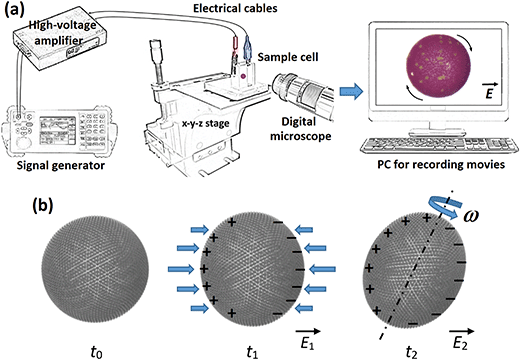
The experimental set-up consisted of a signal generator (SDG1025, SIGLENT Technologies), a high-voltage amplifier (20HVA24-BP1, HVP), a digital microscope (AM7315MZT, Dino-Lite) for viewing perpendicular to the direction of the applied E-field, a light source (KL 300 LED, Schott AG), a computer for collecting images and recording videos, and an optical glass cuvette (18 mm × 10 mm × 30 mm) used as a sample cell with two copper plates that constituted electrodes (with a gap of 15.4 mm). The sample cell was placed on a mechanical XYZ translation stage to ease its positioning relative to the optical path of the microscope. A schematic figure illustrating part of the experimental set-up is shown in Fig. 1a.2.2. Materials
Castor oil (MA-220-1, density of ∼0.96 g cm−3 at 25 °C, electrical conductivity of ∼50–100 pS m−1, relative permittivity ∼4.7 and kinematic viscosity of ∼750 cSt at 25 °C) was purchased from Mareo, Poland. The oil has similar properties to the oil we previously used in our laboratory, that is, the castor oil purchased from Sigma-Aldrich (83912). Silicone oils (Rhodorsil Oils 47, with different viscosities in range 50–10000 cSt at 25 °C, density 0.96–0.97 g cm−3 at 25 °C, electrical conductivity of ∼5–10 pS m−1, and relative permittivity ∼2.8) were purchased from VWR Chemicals, USA. Castor oil and silicone oil are immiscible with an interfacial tension between them ∼4.5 mN m−1. Polystyrene particles (PS, with a diameter of ∼10 μm and ∼40 μm and density of ∼1.05 g cm−3) were bought from Microbeads AS, Norway. The surface of PS particles was modified as described in ref. 41 to change the three-phase contact angle and increase their affinity towards silicone oil so that the particles attach strongly to the oil–oil interface (as in the case of the PE particles). For the surface modification, the ratio of acrylate polymer surface modifier (FluoroPEL PFC 502AFA, Cytonix, USA) to methoxy-nonafluorobutane solvent was 1![[thin space (1/6-em)]](https://www.rsc.org/images/entities/char_2009.gif) :
:![[thin space (1/6-em)]](https://www.rsc.org/images/entities/char_2009.gif) 300. The modified PS particles had density ∼1 g cm−3, electrical conductivity <10−11 S m−1, and relative permittivity ∼2.6. Clay mineral particles (Li-fluorohectorite, a synthetic 2
300. The modified PS particles had density ∼1 g cm−3, electrical conductivity <10−11 S m−1, and relative permittivity ∼2.6. Clay mineral particles (Li-fluorohectorite, a synthetic 2![[thin space (1/6-em)]](https://www.rsc.org/images/entities/char_2009.gif) :
:![[thin space (1/6-em)]](https://www.rsc.org/images/entities/char_2009.gif) 1 clay) were received from Prof. J.O. Fossum (NTNU, Trondheim, Norway). Similar clay particles were partially characterized in work.42 They were polydisperse in size, from hundreds of nm to 10 μm, density of ∼2.5 g cm−3, electric conductivity ∼10−6 S m−1 and dielectric constant ∼6. Polyethylene particles (PE, red coloured and cyan coloured, size of ∼50 μm and density of ∼0.98 g cm−3, and blue coloured, size of ∼50 μm, and cyan coloured, size of ∼30 μm, all with a density of ∼1 g cm−3, electrical conductivity <10−12 S m−1, and relative permittivity ∼2.1) were purchased from Cospheric LLC, USA.
1 clay) were received from Prof. J.O. Fossum (NTNU, Trondheim, Norway). Similar clay particles were partially characterized in work.42 They were polydisperse in size, from hundreds of nm to 10 μm, density of ∼2.5 g cm−3, electric conductivity ∼10−6 S m−1 and dielectric constant ∼6. Polyethylene particles (PE, red coloured and cyan coloured, size of ∼50 μm and density of ∼0.98 g cm−3, and blue coloured, size of ∼50 μm, and cyan coloured, size of ∼30 μm, all with a density of ∼1 g cm−3, electrical conductivity <10−12 S m−1, and relative permittivity ∼2.1) were purchased from Cospheric LLC, USA.
2.3. Formation of particle-covered droplets
We used an E-field approach (see ref. 43) to form a monolayer particle shell on the surface of a silicone oil droplet. Initially, a silicone oil dispersion of particles was prepared where the particle concentration was adjusted to form a particle-covered droplet of a certain size. A droplet with particles was formed (using a regular mechanical pipette) in a cuvette filled with castor oil. Next, an E-field (∼200 V mm−1) was applied to guide (by electrostatic force) the particles in the bulk liquid of the dispersion droplet toward the droplet's interface. The particles at the droplet interface were irreversibly trapped by capillary force, which in the case of microparticles is a few orders of magnitude greater than the thermal energy.44 As the particles reached the surface of the droplet, they were carried toward the electric equator of that droplet by E-field-induced liquid flows. These flows moved particles within the droplet's surface, made them pack into a ribbon-like structure, which gradually widened and eventually (after ∼10 min) covered the droplet surface. The shell particles were arranged in a packed and nearly hexagonal structure. In the experiments with droplets covered by PS particles, we added a small amount (a few particles) of coloured PE particles to make it easier to track the particle position and estimate the rotation rate.We also prepared a droplet covered with a Janus particle shell, i.e., a heterogeneous shell composed of two different particle types (red and blue PE particles). Firstly, we formed two droplets partially covered with particles (around 70% coverage), one with red PE particles and the other one with blue PE particles using the same procedure as described above. The droplets were then mechanically brought into close proximity. Subjected to a DC E-field (200 V mm−1), the droplets attracted one to another and eventually coalesced forming a droplet with a heterogeneous monolayer shell comprising densely packed particles. This particle-covered droplet was used in the experiment on solid-to-liquid transition of a particle shell.
2.4. Experimental procedures
In our experiments on electrorotation of particle-covered droplets (and pure silicone oil droplets, as well as individual PE and PS particles, used as the reference data), we varied the E-field strength and droplet size, as well as the silicone oil viscosity, and studied (i) changes of the deformation magnitude of droplets, (ii) tilt angle, and (iii) rotation rate. The E-field was always applied in the horizontal direction. At weak E-fields, a particle-covered droplet deforms, and when stronger E-fields are applied the deformed droplet starts rotating, as sketched in Fig. 1b. The deformation is here defined as D = |(d1 − d2)/(d1 + d2)|, where d1 and d2 are the droplet minor and major axes, respectively. The tilt angle is measured between the major axis and the vertical direction, i.e., its value is zero when the major axis is normal to the E-field direction.In the experiments on electrorotation, the strength of the DC E-field was increased stepwise (0–835 V mm−1) and each step was maintained for at least 1 minute. The deformation magnitude and rotation rate were calculated by averaging three data points collected at each E-field strength. The tilt angle values are presented using a candlestick chart, which shows the dynamic changes of the tilt values at each E-field strength. Red and blue colours indicate the decrease and increase of the absolute value of the tilt angle within one-minute measurement at a specific E-field strength. The errors included in some plots were estimated using standard deviation of the measurements. In several plots the error bars are omitted for figure clarity. The fundamental studies were followed by experiments demonstrating applications of the E-field method. The details on experimental procedures of these experiments are described in the paragraphs corresponding to the presented data. We used graphical software GIMP (v. 2.10) and Wondershare Filmora (v. 9.5) to edit collected pictures and movies.
3 Results
3.1. Electrorotation of a particle-covered droplet – fundamentals
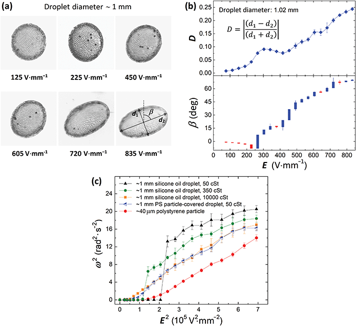
A medium size droplet (diameter of ∼1 mm) of silicone oil (50 cSt) covered by PS particles (40 μm) was subjected to an E-field. Initially, in the absence of the E-field, the droplet was spherical with a shell composed of densely packed particles. Application of weak E-fields (<225 V mm−1) resulted in compressive deformation of the droplet, i.e., the droplet deformed to an oblate shape (see images in Fig. 2a). At the time scale of the experiments conducted at weak fields (∼1 min) we did not observe rotational motion of the droplet. Slow rotation of the particle-covered droplet was observed above 225 V mm−1, and from ∼265 V mm−1 the rotation rate increased nearly linearly with the increase of the E-field strength. The images in Fig. 2a show qualitatively the deformation and orientation of the particle-covered droplet at different E-field strengths.The quantitative analysis is presented in Fig. 2b where we plotted the magnitude of the droplet deformation and the tilt angle versus the E-field strength. At weak E-fields (at which droplet rotation was not observed), the magnitude of the deformation grew slightly faster than the square of the E-field strength (see Fig. S1 and the corresponding description for more details, ESI†). However, as the droplet started tilting and rotating, the magnitude of the deformation decreased locally leaving a bump in the D vs. E plot. The peak of this local bump is roughly in the place where the electrorotation of the droplet was clearly observed. A similar observation was made for clean droplets.17 As the E-field was further increased, both the magnitude of the deformation and the tilt angle steadily increased. At the strongest E-fields, the droplet rotated very fast (∼4 rad s−1), was stretched rather than being compressively deformed. When the droplet deforms (while subjected to the E-field) and its surface area increases, the particle coverage decreases. We estimated (via image analysis) that the particle coverage for the spherical droplet (before application of the E-field) used in the experiment presented in Fig. 2 is around 0.83. At the strongest E-field, the deformation magnitude of the droplet was around 0.24. At this geometry, the droplet surface area increased by around 6% compared to the spherical geometry (deformation close to 0). With the increased surface the particle coverage decreased to around 0.78. The particles then had more room to move, and the droplet's rotational motion resembled tank-treading by appearance.
In Fig. 2c, we plotted the square of the rotation rate against the square of the E-field strength for the 1 mm PS particle-covered droplet (blue left-pointing triangles). As a reference, we also performed experiments on a single 40 μm PS particle and pure silicone oil droplets of three different viscosities: 50, 350 and 10![[thin space (1/6-em)]](https://www.rsc.org/images/entities/char_2009.gif) 000 cSt. We chose to present the data in such a way (ω2vs. E2) to find the correlation with the E-field strength and compare it with the classical description of rotating spherical particle, where the rotation rate scales as:17,35
000 cSt. We chose to present the data in such a way (ω2vs. E2) to find the correlation with the E-field strength and compare it with the classical description of rotating spherical particle, where the rotation rate scales as:17,35
The data from the experiments on the particle-covered droplet and the pure silicone oil droplet with the highest viscosity almost overlap. This indicates that the particles forming a shell contribute greatly to the viscous effects slowing down the droplet rotation (by reducing the straining flows, see discussion in Section 4.3) as compared with the pure droplet of the same viscosity (that is 50 cSt). On the other hand, the presence of particles on the droplet's interface shifts the onset value of E-field at which the rotation begins. In the case of pure oil droplets, the charges that built up at the droplet interface are convected away by the electrohydrodynamic (EHD) flows generated by the E-field.23 The charge convection is generally greater for droplets with lower viscosities, and therefore the onset value of E-field increases (see Fig. 2c). The EHD flows vanish when particles are added to the interface (see flow velocity maps in our work in ref. 28). The electric stress on a particle-covered droplet is therefore larger compared to that acting on the pure oil droplet of the same size and viscosity (at the same E-field strength) explaining why electrorotation of particle-covered droplets initiates at weaker E-field strengths compared to pure droplets (of the same viscosity).
Remarkably, the rotation rate of a particle-covered droplet is nearly identical to that of a high-viscosity droplet, and very different from a PS particle. This observation suggests that there is a small change to the droplet*s electric properties with the addition of particles. The difference between the critical E-field for the viscous droplet and particle-covered droplet is small and could be due to differences in deformation or a weak straining flow. However, these differences disappear once rotation sets in.
Moreover, we learned that the rotation data from the experiment on the single PS particle looks the most linear (Fig. 2c). The other curves look linear only at weak E-fields. At stronger fields, the curves consistently bend downward. This may indicate that the deformation of droplets (with or without particles) affects the rotation rate. We decided to further investigate this, and study droplets with different size, knowing that the droplet deformation is proportional to its size.28–30
To study the influence of droplet size on electrorotation we prepared droplets with different diameters. We used silicone oil with a viscosity of ∼50 cSt and PS particles (same parameters as in the previous experiments). Each droplet was subjected to an E-field that was increased stepwise from 0 to 835 V mm−1. Each step was maintained for ∼1 minute. In Fig. 3a we present pictures of four particle-covered droplets at four different E-field strengths. For the droplet dynamics see the corresponding Movie S1 (ESI†).
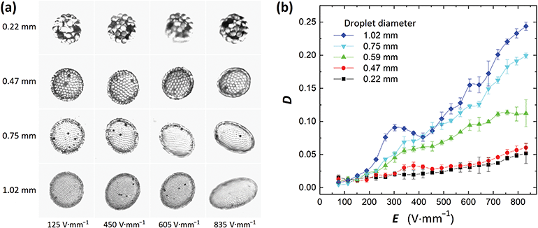 | ||
| Fig. 3 (a) Images of four PS particle-coated droplets subjected to different E-field strengths. See also the corresponding Movie S1 (ESI†). (b) The magnitude of deformation is plotted against the E-field strength. D is roughly proportional to d·E2 within the studied range of E-field strengths, where d is the droplet diameter. There is also a characteristic bump in each data set, and the peak of the bump proceeds the initiation of droplet rotation. | ||
Our experiments show that at the same E-field strength, the smallest droplet deformed the least, whereas the largest droplet deformed the most (Fig. 3b). It is not trivial to precisely predict how the magnitude of deformation theoretically scales with the E-field. That is because the droplet's geometry changes from oblate to nearly prolate, the surface area of the droplet increases, and at the same time, the particle coverage changes when E-field strength is increased. From the data presented in Fig. 3b, we can see that D is roughly proportional to d·E2 within the studied range of E-field strengths, where d is the droplet diameter. This phenomenon can be exploited for applications as it will be demonstrated in Section 3.2 where particle rearrangement within the shell (by unjamming the particles) is possible above a certain value of D. In Fig. 3b we also observe the characteristic bump in all of the D vs. E plots. Similarly, to the experiment presented in Fig. 2b, the peak of the bump proceeds the initiation of droplet rotation. In Fig. 4a and b we plot ω2vs. E2 for the all the studied droplets with PS particle shells. We split the data into two plots for better clarity, and also to highlight that the behavior of small droplets (below 0.8 mm) differs from that of larger droplets.
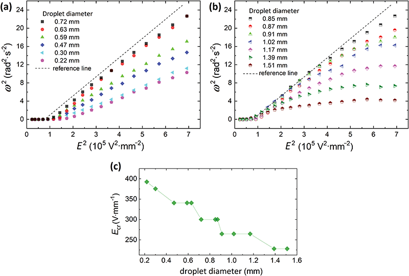 | ||
| Fig. 4 Rotation rate of particle-covered droplets with a diameter of (a) 0.22–0.72 mm and (b) 0.85–1.51 mm. (b) The rotation rate consistently decreased and the curves deviated more from the linear trend (observed in panel (a)) with the increase of the droplet diameter. (c) Critical field (Ecr) at which the droplet started rotating plotted against the diameter of a droplet. The data series presented in panels (a and b) were also plotted in Fig. S2 (ESI†), where the argument values for each data series were normalized by the corresponding value of Ecr taken from panel (c). | ||
Interestingly, unlike the classical description of Quincke rotation of rigid particles (see the equations for ω and EQ on the previous page), the rotation of the deformable particle-covered droplets is size-dependent, i.e., both the rotation rate and the critical E-field for rotation are size-dependent (see also Fig. 4c). We therefore, use a different notation for the critical E-field for the onset of the rotation in our system, Ecr. Size-dependency of the critical E-field was theoretically shown to exist, for example, for insulating cylinder particles, and it originated from ion diffusion and electro-migration in the charge layer.11 However, these phenomena prevail for small rotating objects, at least one order of magnitude smaller than particle-covered droplets used in this study. Here, in the three-phase soft-matter system, the size-dependency of Ecr can originate from droplet deformation (similar as for clean droplets).20 Larger particle-covered droplets are easier to deform, and thus initiate rotation at weaker E-fields. As shown in Fig. 4c, the Ecr(d) is consistently decreasing with the droplet diameter (d).
To verify if the droplet deformation may cause Ecr shifting, we performed an experiment using a droplet with a rigid shell composed of sintered PS particles. The results are presented in Fig. 5a and b. Subjected to an E-field the droplet rotated without being deformed (see images in Fig. 5b). The critical field for electrorotation was found to be around 360 V mm−1 (the value is similar to that of an individual PS particle), far from the Ecr of a deformable droplet of similar diameter (∼1.39 mm) covered by unsintered PS particles (which started rotating at ∼250 V mm−1).
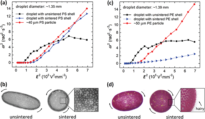 | ||
| Fig. 5 Electrorotation of droplets with rigid and deformable shells composed of (a and b) PS particles and (c and d) PE particles. The rigid shells were made by joining particles through heating using a microwave oven. Characteristic necks between sintered PS particles are shown in the zoomed image in panel (b). During heating of the PE particle-covered droplet, hairy polymeric structures were formed sticking out of the shell, as presented in the zoomed image in panel (d). The change of the morphology of the PE particle shell formed on an oil droplet affected its rotation rate (see also corresponding Movie S2, ESI†). | ||
The experiment also shows that the rotation rate of the droplet with a rigid PS particle shell is roughly linearly proportional to the E-field strength. This is not the case for the deformable droplet covered with unsintered particles. The data points corresponding to the measurements of the deformable droplet band downward. The deviation from the linear trend is consistently greater for larger droplets, as presented in Fig. 4b. For example, the rotation rate of 0.85 mm particle-covered droplet follows the linear trend up to around 3 × 10⁵ V2 mm−2, the 1.02 mm droplet follows the trend to around 2 × 10⁵ V2 mm−2, whereas the rotation rate of the largest droplet size of 1.51 mm is non-linear practically for all E-field strengths.
The rotation rate is also affected by the morphology of particle shells. In Fig. 5c and d we present the results from the experiments on electrorotation of PE particle-covered droplets with different morphologies of their shells. We prepared two droplets (diameter of ∼1.39 mm) both covered by PE particles (50 μm). One of the droplets was heated in a microwave oven (600 W) for several seconds to partially melt the PE particles. This led to the fusing of the PE particles and the formation of a rigid shell. During the heating, brush or hairy-like shell was formed (see the zoomed image in Fig. 5d). The two particle-covered droplets were then subjected to an E-field. The droplet with hairy shell rotated significantly slower than the droplet with a smooth shell. We expect this is due to the increase of the magnitude of drag coefficient (see also the corresponding Movie S2, ESI†) and/or due to the changes of the effective electric properties of the particle shell. Kabir et al.45 studied how the particle surface morphology affected the drag force acting on a particle. They measured the drag coefficient to be at least 20% higher for a hairy particle compared to that of a smooth surface, which is aligned with our anticipations. We observed that many hairs that initially (before electrorotating) protruded almost perpendicular to the particle shell were flattened due to the liquid drag as the droplet started spinning faster when the E-field was increased (see an analogous experiment with a tennis ball).46 This change in the hair alignment should favor faster rotation of the shell. Indeed, the measured rotation rate for the hairy PE shell (blue triangles in Fig. 5c) supports this (the rotation rate is accelerated with increasing E-field strength). The heating of PE particles that led to the formation of hairy structures could also affect the electric properties of the shell. This will have to be investigated in more detail.
Furthermore, the electrorotation of the particle-covered droplet can be affected by the electrical nature of the particles. To electrorotate an object immersed in a low conducting liquid it is required that the rotor's electrical conductivity (or dielectric constant, see the equation for Maxwell–Wagner relaxation time) is lower than that of the media fluid. An interesting situation happens when a shell on a droplet is composed of non-ohmic particles, i.e., having a non-linear relationship between the electric current and the voltage. In Fig. 6, we present the results from an experiment, in which a silicone oil droplet (∼0.7 mm) was covered by clay mineral particles. Subjected to an E-field of around 270 V mm−1 the droplet slowly rotated with a rotation rate of around 0.2 rad s−1. The rotation rate was increased by increasing the E-field strength up to around 300 V mm−1. However, at E ∼ 330 V mm−1 the clay particle-covered droplet stopped rotating. The dipole moment of the droplet covered by the clay film flipped at E > 330 V mm−1. As a consequence, the E-field acting on the droplet stretched it along the E-field direction (see Fig. 6 and the corresponding Movie S3, ESI†).
 | ||
| Fig. 6 A silicone oil droplet (50 cSt) covered by non-ohmic clay particles (Li-fluorohectorite). The droplet electrorotated in E-field range of around 270 to 330 V mm−1. At stronger E-fields (e.g., 350 and 400 V mm−1) the electric dipole induced on a droplet was flipped resulting in the droplet electrostretching (see also the corresponding Movie S3, ESI†). E-Field was applied horizontally, and the positive signal was on the left side of the droplet. The blue arrows indicate the direction of the electric stress acting on the droplet. | ||
3.2. Towards applications
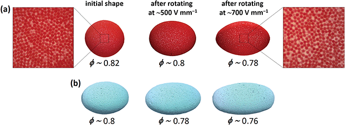
In this section, we present examples of application of electrorotation of particle-covered droplets. In the first example, we demonstrate that the electrorotation enables fabrication of arrested droplets with different geometries and with shells having different porosity (or particle coverage). We prepared two silicone oil droplets covered with polyethylene (PE) particles. One droplet was initially spherical (Fig. 7a) and the other droplet was aspherical (Fig. 7b) made by coalescing two droplets, as shown in Fig. S3, (ESI†). To tune the shape of the droplets we electrorotated them at strong E-fields (500 and 700 V mm−1) for a few seconds.We know from fundamental studies that as a particle-covered droplet rotates at strong E-field, it also stretches and allows the particles in the shell to separate from one another. By turning off the E-field, the droplet relaxes and reduces its surface area thus forcing the particles to form a shell again. However, the particle-covered droplets did not return to their initial shapes, and the structure of their shells was more disordered and porous compared to that of the initial shells (as shown in Fig. 7 and Movie S4, ESI†). That happened because the particles did not have sufficient time to find optimal arrangements when the surface area decreased fast after switching off the E-field. We found that the application of stronger E-fields (e.g., 700 V mm−1) resulted in formation of more elongated arrested droplets with more porous particle shells. We estimated that the particle coverage decreased by around 0.02 and around 0.04 when the droplets were stretched and rotated at 500 and 700 V mm−1, respectively (compared to the particle coverage value of droplets before electrorotation). The elongated droplets remained stable, i.e., they did not change shape, and we did not observe particle rearrangements.
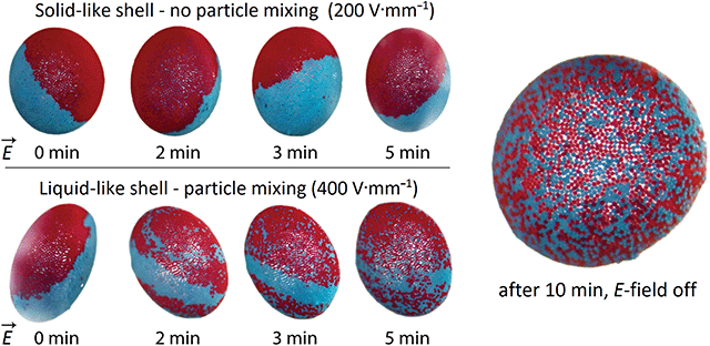
In the next experiment, we demonstrate how electrorotation can be utilized to mix particles and study solid to liquid transition of the particle layer. We performed an experiment on a droplet (diameter around 3 mm) covered with a Janus shell made of 50 μm PE particles (red and blue), suspended in castor oil, and subjected to different E-field strengths. Fig. 8 shows the time development of a Janus shell subjected to a weak (200 V mm−1) and strong (400 V mm−1) E-field. Subjected to the weak E-field, the droplet with the Janus shell rotated almost as a solid sphere being slightly deformed. The particles forming the shell were practically jammed and, therefore, could not mix. After 5 minutes and several rotations, the border separating the blue and red particles is still intact; confirming that the particle layer acts as a particle film. Subjected to the stronger E-field, the particle-covered droplet deformation was large enough (D > 0.1) for the particle film to liquefy. As seen in Fig. 8 (bottom raw), the particles started to mix, and the border separating the two particle shells of different colour split up. Eventually, after several minutes of electrorotation, the particles were almost completely mixed.
To study the efficiency of electrorotation on particle mixing, we used droplets (diameter ∼2 mm) covered with a Janus shell made of 50 μm PE particles (red and cyan). E-Fields of 260, 450 and 700 V mm−1 were applied during the experiments (see also Movie S5, ESI†). Images of the droplets (Fig. 9a–c) were captured as the droplets finished 3, 5, 10 and 40 revolutions (Rev). With this methodology, we could qualitatively compare the degree of particle mixing. We found that the efficiency of particle mixing depends on the E-field strength, i.e., the particles mixed faster at stronger fields. This is because droplets subjected to strong E-fields deform more and thus make more space at the droplet surface for particles to rearrange, and the particles at the surface move faster and may collide and pull on other particles. Moreover, we observed that the particle mixing depends on the droplet size (compare Fig. 9c and d). We also observed that the E-field strength at which solid-to-liquid transition and particle mixing initiates depends on the size of the surface particles. However, we do not have sufficient data to be conclusive on this point. Nevertheless, the data presented here should serve as an entry point for formulating theoretical models of the solid-to-liquid transition of particle shells and particle mixing induced by E-fields.
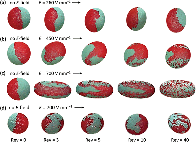 | ||
| Fig. 9 Droplets with a diameter of (a–c) ∼2 mm and (d) ∼0.8 mm covered with 50 μm PE particles (red and cyan) forming a Janus shell. Fast particle mixing is facilitated by the application of stronger E-fields. The particles mix slower at the surface of the smaller droplet. See also the corresponding Movie S5 (ESI†). | ||
The knowledge gained from the experiments on individual droplets can be also very useful in studying and advancing more complex systems, such as emulsions. Recently, we were exploring the possibility offered by E-fields to fabricate Pickering emulsions through a limited coalescence approach.47 We used E-fields to promote the attraction of droplets partially covered by particles. That enabled speeding up the droplets’ coalescence that led to the formation of stable emulsion droplets, i.e., densely covered by particles. However, during the Pickering emulsion formation, many droplets formed unwanted electrorheological chain-like structures often composed of particle-bridged droplets. This prevented completion of the Pickering emulsion maturing and caused the formation of droplet clusters.
In this example of the application of electrorotation phenomena, we demonstrate that the droplet chaining and clustering (see left panels in Fig. 10) can be prevented. During the formation of Pickering emulsion by E-field-assisted electrocoalescence, we cyclically (every 20 seconds) increased and decreased the E-field strength. In Fig. 10a, we present a sequence of optical microscopy images. These images were recorded within 20 seconds, roughly in the middle of the process of fabricating a Pickering emulsion (that took ∼30 min, see ref. 47 for a similar experiment showing the whole process of emulsion maturing). Switching between the critical E-field for rotation E < Ecr and E > Ecr, enabled droplet coalescence at weak fields and destruction of droplet agglomerates at strong fields.
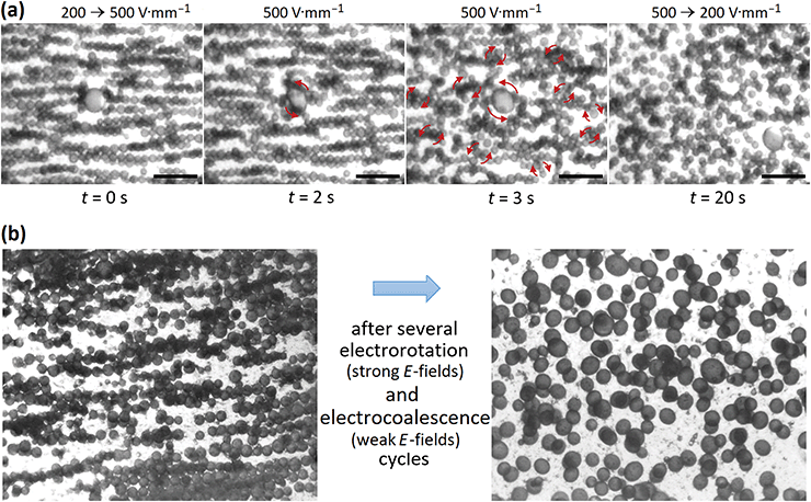 | ||
| Fig. 10 Optical microscope images of emulsions droplets covered by 10 μm PS particles. (a) An E-field of 500 V mm−1 was applied for ∼20 seconds to induce electrorotation of droplets and droplet clusters to help the clustered droplets to separate. See also the corresponding Movie S6 (ESI†). The scale bars are 1 mm. (b) Many droplets formed unwanted chain-like structures and clusters (left panel). Application of E-fields in an alternating fashion (weak ↔ strong) resulted in cluster disintegration and enabled the formation of separated emulsion droplets (see right panel) with an average diameter of ∼250 μm. | ||
As presented in Fig. 10a, at strong E-field (500 V mm−1), droplets and droplet clusters started rotating and shearing the emulsion locally. These dynamics helped the clustered droplets to separate. The rotation of individual droplets and droplet clusters (before their destruction) is shown in the corresponding Movie S6 (ESI†). In Fig. 10b, the electrorotation of selected droplets is marked with red arrows. For the sake of image clarity, we only marked selected droplets. Before lowering the E-field strength back to 200 V mm−1, nearly all droplets were separated and rotated individually. This procedure of alternating the strengths of the E-field resulted in the formation of a Pickering emulsion where the majority of droplets were densely covered by particles (see right panel in Fig. 10b).
Currently, we are also exploring how electrorotation could be used to produce oil–oil Pickering emulsions with nearly monodispersed Pickering droplet size. We use electrorotation to prevent droplet clustering and also split droplets at even stronger fields (three levels of E-field strengths are used) to coalesce them again with other droplets to even the particle concentration in each droplet. Once more, electrorotation is the key to efficient formation of stable particle emulsions.
4 Comments
4.1. Three-phase system
In our study, we mainly used droplets with polymeric shells composed of spherical microparticles (10–50 μm) as a model system. However, the presented methodology is not limited to droplets with this type of shell, as long as: (i) the particles’ electrical properties fulfil the condition for electrorotation, and (ii) the particles are strongly bound to the oil–oil interface and do not detach when sheared during droplet rotation. In our laboratories, we performed several additional experiments with droplets as small as 100 μm and as large as 0.5 cm, using different types of particles, including poorly conductive kaolinite particles and silica particles, as well as polymeric particles, and these had a broad size range of 500 nm to 0.2 mm. In our experiments, we used castor oil as the surrounding liquid. However, as presented in several other studies, other combinations of liquids can also be used.15,484.2. Electric field parameters
In the experiments presented here, we used DC E-fields between 0 to 835 V mm−1 because stronger E-fields resulted in a break-up of the largest droplet (i.e., the particle-covered droplet with a diameter of around 1.51 mm). However, in principle, smaller droplets (e.g., a diameter of 100 μm) can be exposed to E-fields far above a few kV mm−1 because they deform less, as presented in Fig. 3b, and thus break up at stronger E-fields compared to larger droplets. Also, droplets with higher viscosities than those used here can be subjected to stronger E-fields, as their characteristic time of deformation may be smaller than the charge build-up time.We noted that there is a major difference in droplet behaviour depending on how the E-field is applied, that is, whether the strong E-field is reached instantly or gradually. The instant application of a strong E-field may cause significant deformation of a droplet accompanied by an irreversible detachment of particles from the droplet's surface (see Fig. S4 and Movie S7, ESI†). We also observed that when the E-field was increased gradually, the particle-covered droplets tumbled less compared to particle-covered droplets exposed to sharply changing E-field strengths. Because the droplet's behaviour at each E-field strength was studied for short time (∼1 minute), we cannot conclusively state whether a steady shape is reached. However, the data collected for the experiment on particle mixing indicates that the steady shape (and tilt angle) can be achieved after several minutes of electrorotation (see Movie S5, ESI†). We also noted that the direction of the Quincke rotation can be changed by flipping the E-field direction.
As presented in Fig. 6, the fluorohectorite clay particles had interesting electrical characteristics limiting the electrorotation at stronger E-fields so that the electrorotation was achieved only at the narrow E-field band (that is, for 270 V mm−1 < E < 330 V mm−1). We think that the bandwidth can be modified. The electrical properties of clay mineral particles depend on the type of clay used (fluorohectorite, LAPONITE®, kaolinite, etc.), their water content, and also their size. Thus, by controlling these parameters one can design a particle-covered droplet with the desired E-field bandwidth of droplet electrorotation.
4.3. Straining flows
As we described in the Section 3.1, the size-dependency of Ecr (shown in Fig. 4c) originated from droplet deformation. The increased deformation increases the dipole strength, and thus decrease Ecr. On the other hand, when the droplet deforms (while subjected to the E-field) and its surface area increases, the particle coverage decreases, which enables formation of EHD flows. These straining flows may convect away the charge accumulated on the droplet's interface (especially relevant for low viscosity droplets) decreasing the strength of the electric dipole, which should lead to increased Ecr values. From our experimental data presented in ref. 28, we learnt that the straining flows created near the small opening in the particle shell (formed at the droplet's electric equator) are very weak compared to those formed around a particle-free droplet, and narrow (located only near to the opening). Therefore, we believe their contribution to the change of the Ecr value is negligible in our system. However, at larger droplet deformation (when a particle-covered droplet rotates), the straining flows may play a more significant role, for example, in particle mixing, as presented in Fig. 9.5 Conclusions
We experimentally studied electrorotation of particle-covered droplets (and pure silicone oil droplets, as well as individual PE and PS particles, used as reference data) immersed in electrically more conductive castor oil. We showed that the addition of particles to the droplet interface changes the parameters of electrorotation compared to those of pure droplets and solid particles. The surface particles contributed to the viscous effects, slowing down the droplet rotation compared to the particle-free droplets, and their presence shifted the onset value of the critical E-field strength (at which the rotation begins). We also reported the presence of a second critical E-field (at which the rotation terminates) for the droplets covered by non-ohmic particles. We found that the rotation rate (ω) and the critical E-field for rotation (Ecr) depend on the size of particle-covered droplets, dissimilar to the macroscopic spherical particles for which the Quincke description is held. We also observed that both ω and Ecr depend on particle shell morphology and composition.We have also presented new applications for Quincke rotation of particle-covered droplets. (i) We demonstrated that this electric phenomenon can be used to form arrested droplets with non-spherical shells. In the context of the stability and applications of particle-covered droplets (e.g., constituting Pickering emulsions), it is important to understand their mechanical properties. Several research groups have studied the deformation, relaxation, and mechanical properties of particle-covered droplets.27,49,50 The majority of the research concern spherical droplets. However, very little is known about arrested droplets with non-spherical particle shells. The method presented here enables the formation of arrested droplets with controllable geometry and porosity, and thus, facilitates research, for example, on deformation, yielding, and crumpling of jammed particle shells formed on arrested droplets (that is ongoing research in our laboratories). (ii) We also introduced a novel experimental approach for monitoring the dynamics of particles forming a monolayer on the surface of droplets by using a droplet covered with a Janus shell. This setup enabled particle tracing and direct visualization of the transition from solid-like rotation to the fluid-like tank-treading motion of a particle-covered droplet. (iii) Furthermore, we demonstrated that the electrorotation of deformable droplets permitted particle mixing on the interface of droplets and the formation of patchy particle shells. (iv) Finally, we showed that electrorotation can be used to facilitate efficient fabrication of Pickering emulsions.
Future experimental studies should investigate how particle properties, e.g., their cohesiveness, particle packing, and particle coverage, affect the mechanics of particle shells and electrorotation of particle-covered droplets. The role of the straining flows in electrorotation of large-size particle-covered droplets should be investigated in more detail. It would also be interesting to study interactions of two or more deformable particle-covered droplets electrorotating in close proximity.
Author contributions
Z. Rozynek. and A. Mikkelsen initiated the project. Z. Rozynek, A. Mikkelsen and J. Banaszak designed all experiments. J. Banaszak performed the experiments with results presented in Fig. 2–5 and Fig. S2 (ESI†). K. Khobaib performed the experiments with results shown in Fig. 7, 9 and Fig. S3 (ESI†). A. Mikkelsen performed the experiments with results presented in Fig. 8. Z. Rozynek performed the experiments with results presented in Fig. 6, 10 and Fig. S1, S4 (ESI†). Z. Rozynek wrote the first version of the manuscript. All authors took part in discussions towards the finalization of the manuscript. Z. Rozynek administered the submission and the review process.Funding sources
A. Mikkelsen received funding from the European Union's Horizon 2020 Research and Innovation Framework Program under the M. Skłodowska-Curie grant agreement no. 752896. Z. Rozynek, J. Banaszak and K. Khobaib received funding from the Polish National Science Centre through OPUS and PRELUDIUM program (2015/19/B/ST3/03055 and 2019/35/N/ST5/02821). We thank the Research Council of Norway through its Centres of Excellence funding scheme, Project No. 262644.Conflicts of interest
There are no conflicts of interest to declare.References
- Y. Hu, P. M. Vlahovska and M. J. Miksis, Phys. Rev. E, 2018, 97, 013111 CrossRef CAS PubMed.
- A. I. Grachev, Tech. Phys. Lett., 2018, 44, 716–718 CrossRef CAS.
- T. Mochizuki, ACS Omega, 2018, 3, 1031–1040 CrossRef CAS PubMed.
- Y. Dolinsky and T. Elperin, Phys. Rev. E: Stat., Nonlinear, Soft Matter Phys., 2009, 79, 026602 CrossRef PubMed.
- P. García-Sánchez, Y. Ren, J. J. Arcenegui, H. Morgan and A. Ramos, Langmuir, 2012, 28, 13861–13870 CrossRef PubMed.
- Z. M. Sherman and J. W. Swan, Phys. Rev. Lett., 2020, 124, 208002 CrossRef CAS PubMed.
- W. Weiler, Phys. Chem., 1893, 194–195 Search PubMed.
- G. Quincke, Ann. Phys., 1896, 295, 417–486 CrossRef.
- T. B. Jones, IEEE Trans. Ind. Appl., 1984, 20, 845–849 Search PubMed.
- I. Turcu, J. Phys. A: Math. Gen., 1987, 20, 3301–3307 CrossRef.
- F. Peters, L. Lobry, A. Khayari and E. Lemaire, J. Chem. Phys., 2009, 130, 194905 CrossRef CAS PubMed.
- Q. Brosseau, G. Hickey and P. M. Vlahovska, Phys. Rev. Fluids, 2017, 2, 014101 CrossRef.
- Y. Gu and H. Zeng, Phys. Rev. Fluids, 2017, 2, 083701 CrossRef.
- E. Lemaire and L. Lobry, Phys. A, 2002, 314, 663–671 CrossRef.
- S. Krause and P. Chandratreya, J. Colloid Interface Sci., 1998, 206, 10–18 CrossRef CAS PubMed.
- J. Q. Feng, J. Colloid Interface Sci., 2002, 246, 112–121 CrossRef CAS.
- H. He, P. F. Salipante and P. M. Vlahovska, Phys. Fluids, 2013, 25, 032106 CrossRef.
- A. N. Tyatyushkin, Phys. Fluids, 2017, 29, 097101 CrossRef.
- J.-W. Ha and S.-M. Yang, Phys. Fluids, 2000, 12, 764–772 CrossRef CAS.
- P. F. Salipante and P. M. Vlahovska, Phys. Fluids, 2010, 22, 112110 CrossRef.
- P. F. Salipante and P. M. Vlahovska, Phys. Rev. E: Stat., Nonlinear, Soft Matter Phys., 2013, 88, 043003 CrossRef PubMed.
- H. Sato, N. Kaji, T. Mochizuki and Y. H. Mori, Phys. Fluids, 2006, 18, 127101 CrossRef.
- D. Das and D. Saintillan, J. Fluid Mech., 2017, 810, 225–253 CrossRef.
- D. Das and D. Saintillan, J. Fluid Mech., 2017, 829, 127–152 CrossRef CAS.
- E. Yariv and I. Frankel, J. Fluid Mech., 2016, 788, R2 CrossRef.
- A. Mikkelsen, P. Dommersnes and J. O. Fossum, Rev. Cubana Fis., 2016, 33, 47–49 Search PubMed.
- L. Bécu and L. Benyahia, Langmuir, 2009, 25, 6678–6682 CrossRef PubMed.
- A. Mikkelsen, K. Khobaib, F. K. Eriksen, K. J. Måløy and Z. Rozynek, Soft Matter, 2018, 14, 5442–5451 RSC.
- M. Ouriemi and P. M. Vlahovska, J. Fluid Mech., 2014, 751, 106–120 CrossRef CAS.
- M. Ouriemi and P. M. Vlahovska, Langmuir, 2015, 31, 6298–6305 CrossRef CAS PubMed.
- L. Lobry and E. Lemaire, J. Electrost., 1999, 47, 61–69 CrossRef CAS.
- N. Pannacci, L. Lobry and E. Lemaire, Phys. Rev. Lett., 2007, 99, 094503 CrossRef CAS PubMed.
- M. S. Abbasi, R. Song, S. Cho and J. Lee, Micromachines, 2020, 11, 942 CrossRef PubMed.
- A. Jakli, B. Senyuk, G. Liao and O. D. Lavrentovich, Soft Matter, 2008, 4, 2471–2474 RSC.
- G. E. Pradillo, H. Karani and P. M. Vlahovska, Soft Matter, 2019, 15, 6564–6570 RSC.
- A. Zöttl and H. Stark, J. Phys.: Condens. Matter, 2016, 28, 253001 CrossRef.
- A. Bricard, J. B. Caussin, N. Desreumaux, O. Dauchot and D. Bartolo, Nature, 2013, 503, 95–98 CrossRef CAS PubMed.
- S. Q. Lu, B. Y. Zhang, Z. C. Zhang, Y. Shi and T. H. Zhang, Soft Matter, 2018, 14, 5092–5097 RSC.
- D. Das and E. Lauga, Phys. Rev. Lett., 2019, 122, 194503 CrossRef CAS PubMed.
- P. Dommersnes, A. Mikkelsen and J. O. Fossum, Eur. Phys. J.: Spec. Top., 2016, 225, 699–706 CAS.
- Z. Rozynek, M. Kaczmarek-Klinowska and A. Magdziarz, Materials, 2016, 9, 679 CrossRef PubMed.
- A. Mikkelsen, P. Dommersnes, Z. Rozynek, A. Gholamipour-Shirazi, M. D. S. Carvalho and J. O. Fossum, Materials, 2017, 10, 436 CrossRef PubMed.
- P. Dommersnes, Z. Rozynek, A. Mikkelsen, R. Castberg, K. Kjerstad, K. Hersvik and J. O. Fossum, Nat. Commun., 2013, 4, 2066 CrossRef PubMed.
- A. Mikkelsen and Z. Rozynek, ACS Appl. Mater. Interfaces, 2019, 11, 29396–29407 CrossRef CAS PubMed.
- A. M. R. Kabir, D. Inoue, Y. Kishimoto, J. Hotta, K. Sasaki, N. Kitamura, J. P. Gong, H. Mayama and A. Kakugo, Polym. J., 2015, 47, 564–570 CrossRef CAS.
- R. D. Mehta and J. M. Pallis, Sports Eng., 2001, 4, 177–189 CrossRef.
- Z. Rozynek, R. Bielas and A. Józefczak, Soft Matter, 2018, 14, 5140–5149 RSC.
- A. Zakinyan, E. Tkacheva and Y. Dikansky, J. Electrost., 2012, 70, 225–232 CrossRef CAS.
- H. Xu, S. Melle, K. Golemanov and G. Fuller, Langmuir, 2005, 21, 10016–10020 CrossRef CAS PubMed.
- R. B. Karyappa, S. D. Deshmukh and R. M. Thaokar, Phys. Fluids, 2014, 26, 122108 CrossRef.
Footnote |
| † Electronic supplementary information (ESI) available: Seven supplementary movies. See DOI: 10.1039/d1sm00122a |
| This journal is © The Royal Society of Chemistry 2021 |

