
 Open Access Article
 This Open Access Article is licensed under a
 Creative Commons Attribution 3.0 Unported Licence
Resistive force theory and wave dynamics in swimming flagellar apparatus isolated from C. reinhardtii†
Samira
Goli Pozveh
,
Albert J.
Bae‡
and
Azam
Gholami
 *
*
Max Planck Institute for Dynamics and Self-Organization, Göttingen, Germany. E-mail: azam.gholami@ds.mpg.de
First published on 9th December 2020
Abstract
Cilia-driven motility and fluid transport are ubiquitous in nature and essential for many biological processes, including swimming of eukaryotic unicellular organisms, mucus transport in airway apparatus or fluid flow in the brain. The-biflagellated micro-swimmer Chlamydomonas reinhardtii is a model organism to study the dynamics of flagellar synchronization. Hydrodynamic interactions, intracellular mechanical coupling or cell body rocking is believed to play a crucial role in the synchronization of flagellar beating in green algae. Here, we use freely swimming intact flagellar apparatus isolated from a wall-less strain of Chlamydomonas to investigate wave dynamics. Our analysis on phase coordinates shows that when the frequency difference between the flagella is high (10–41% of the mean), neither mechanical coupling via basal body nor hydrodynamics interactions are strong enough to synchronize two flagella, indicating that the beating frequency is perhaps controlled internally by the cell. We also examined the validity of resistive force theory for a flagellar apparatus swimming freely in the vicinity of a substrate and found quantitative agreement between the experimental data and simulations with a drag anisotropy of ratio 2. Finally, using a simplified wave form, we investigated the influence of phase and frequency differences, intrinsic curvature and wave amplitude on the swimming trajectory of flagellar apparatus. Our analysis shows that by controlling the phase or frequency differences between two flagella, steering can occur.
1 Introduction
Cilia and flagella are hair-like organelles, which protrude from the surface of many eukaryotic cells and play a fundamental role in signal processing,1 sensing,2,3 propulsion of micro-organisms4–6 and micro-scale fluid transport7,8 at a low Reynolds number regime. Cilia and flagella are composed of a microtubule-based structure called the axoneme, and the stresses that lead to the whipping motion are due to dynein molecular motors that exert a force between the microtubule doublets by sliding them with respect to each other, converting chemical energy to mechanical work. Constrains at the basal region and along the contour length of the axoneme convert sliding to bending deformations.9–11 The coordinated beating activity of flagella is crucial for efficient swimming of many ciliated cells in an ambient fluid. In response to external stimuli such as light, nutrients, temperature, etc., swimmers transiently change their beating patterns to achieve an efficient directed motion towards the source.The synchronization mechanism between two or more flagella has been an interesting topic in the past and recent years, attracting the attention of both physicists and biologists. Synchronized beating patterns of two flagella in single-celled microorganisms such as biflagellate green alga Chlamydomonas reinhardtii are necessary for a fast directional swimming motion.12 The two flagella of C. reinhardtii typically beat in synchrony for long time intervals before being interrupted by abrupt large reorientations.12,13 It is commonly discussed that interflagellar hydrodynamic interactions between two beating flagella can synchronize their rhythmic patterns.14–20 Goldsein et al.12,13 have analyzed the beats for long time intervals in a series with tens of thousands of beats in micropipette-fixed Chlamydomonas cells and observed synchronized states interrupted by phase slips in cells with a small frequency difference of ≃0.1–1%. However, cells with a high frequency mismatch of ≃10–30% beat asynchronously. Using a low-dimensional stochastic model of hydrodynamically coupled oscillators, namely the stochastic Adler equation,21 they capture the dynamics of phase slips and the statistics of phase-locked intervals. In this stochastic model, noise amplitude is set by the intrinsic fluctuations of single flagellar beats.19 In addition, micropipette experiments by Brumley et al.22 with somatic cells of Volvox carteri confirm that flagella coupled only via ambient fluids can achieve full synchronization despite differences in their intrinsic frequencies.
On the other hand, through experiments performed in ref. 23 with C. reinhardtii, the hydrodynamic force required for the synchronization of two flagella was measured by applying oscillatory external flows and it was found that the force is more than one order of magnitude larger than hydrodynamic forces experienced under physiological conditions. Furthermore, it has been shown24,25 that when the two flagella desynchronize, the rocking of the cell body brings the beating back to synchrony and the contribution of hydrodynamic coupling is negligible to the synchronizing mechanism. However, C. reinhardtii cells held fixed with pipettes are also able to synchronize robustly their flagella,13,26 thus indicating that synchronization is perhaps due to mechanical coupling via internal connecting fibers.27,28 In these micropipette-fixed cells, the rate of synchronization measured experimentally is one order of magnitude higher than rates calculated theoretically in the absence of the swimmer movement by only taking into account the direct hydrodynamic interactions.24 This support the possibility that either small residual rotational degrees of freedom of the cell body or elastic coupling at the basal ends of two flagella contributes to a rapid synchronization. Remarkably, synchronization in mutants of C. reinhardtii missing the filamentous connections is pronouncedly different from wild types.29 Other experiments with C. reinhardtii5,12,30,31 also support the crucial role of mechanical coupling through basal bodies.23,27 These fibers have a microtubule-based structure showing periodic striation patterns.27 The periodicity (around 80 nm in C. reinhardtii) can change in response to chemical stimuli such as calcium ions, indicating the contractility of the fibers.32
On the theoretical side, analyses of a three-sphere model in ref. 25, 33 and 34 have demonstrated that for a free swimmer, synchronization can be achieved in the absence of hydrodynamic interactions solely due to local hydrodynamic drag forces which couple oscillatory motion of two flagella via movements of the swimmer. Remarkably, in this toy model, in the absence of free translational and rotational motions of the swimmer, synchronization of the flagellar phases becomes relatively weak, and so to achieve synchronization in micro-pipette experiments, elastic coupling at the flagellar base or small residual rotational degrees of freedom are required.
Experiments with the isolated flagellar apparatus from a wall-less mutant of C. reinhartii by Hyams and Borisy35,36 have shown that both flagella are able to maintain their beating patterns similar to those found in intact cells. Thus, the presence of a cell body or cytoplasm is not necessary to synchronize two flagella and is possibly an intrinsic structural property of basal apparatus. In the flagellar apparatus, the two flagella are connected at an angle forming a V-shape at their basal ends with elastic fibers connecting the two basal bodies27 are plausible candidates to mechanically couple the oscillatory motion of two flagella and synchronize them. For convenience in microscopy, Hyams and Borisy mainly studied flagellar apparatus anchored to the debris on the substrate and observed that over 70% show synchronous beating patterns, while the rest beat asynchronously. They also observed transient changes from synchrony to asynchrony.
In this work, we studied synchronization dynamics, using phase contrast microscopy, high-speed imaging rates up to 1000 Hz, and image processing to quantify the beating patterns of flagellar apparatus isolated from wall-less mutant of C. reinhardtii. In contrast to experiments by Hyams and Borisy,35,36 we examined free-moving flagellar apparatus where these swimmers can easily translate and rotate while the two flagella beat at two different intrinsic frequencies (∼15% of the mean). Unconstrained swimmer movements couple rhythmically beating flagella and this coupling is strongly influenced if the swimmer is constrained in movement by e.g. attaching to a substrate or holding in place via a micro-pipette. The question we wish to address in this study may be stated as follows: can coupling via filamentous fibers, swimmer movement or interflagellar hydrodynamic interactions bring two flagella in synchrony, if there is such a high frequency mismatch? Our phase analysis with freely swimming flagellar apparatus demonstrates that these couplings are too weak to cause frequency entrainment. The phase dynamics of oscillator flagella shows that they effectively act as two isolated pendulums beating at their own intrinsic frequencies. They perturb one another's phases without ever achieving full synchronization. Furthermore, we used our tracked data to check the validity of resistive-force theory (RFT) which neglects long-range hydrodynamic interactions, and found quantitative agreement between RFT simulations and experimental data with a drag anisotropy of ratio 2. Finally, by using a simplified wave form, we performed simulations and analytical approximations to study the swimming motion of flagellar apparatus. This analysis shows that by controlling the frequency or phase differences between two flagella, steering of flagellar apparatus can occur.
2 Materials and methods
2.1 Isolation of basal apparatus
We used a wall-less mutant of C. reinhardtii (strain SAG 83.81) to isolate flagellar apparatus, following the protocol of Hymes and Borisy.35 Briefly, we grew 1.5 liters cultures of cells in TAP (Tris-acetate-phosphate) medium at 25 °C in a 14 hours light–10 hours dark illumination cycle to reach cell density of ∼106 cells per mL. Cells are centrifuged at room temperature for 15 min at 200 g and resuspended in 100 mL of HMDEK1 solution at 0 °C (10 mM HEPES, 5 mM MgSO4, 1 mM DTT, 0.5 mM EDTA, 25 mM KCL, and pH = 7), spun down again at 800 g for 5 minutes and finally resuspended in 5 mL of HMDEK1. At this step, a small fraction of cells (2–3%) released their flagellar apparatus while most of the cells released single flagella. A subsequent centrifugation at 800 g for 5 minutes sedimented the cell bodies keeping flagella apparatus and single isolated flagella in the supernatant. For reactivation with ATP, we mixed the suspension with an equal volume of HMDEK2 solution (30 mM HEPES, 5 mM MgSO4, 1 mM DTT, 0.5 mM EDTA, 25 mM KCL, and pH = 7) supplemented with 2 mM ATP at pH = 7. Note that isolated flagellar apparatus is able to reactivate without de-membranation, since the membrane terminates in the vicinity of the basal region of flagella, leaving open ends for free diffusion of ATP.35,36 For observation, 10 μL of solution was infused into 100 μm deep flow chambers, built from cleaned glass and 100 μm thick double-sided tape. The glass surface was blocked using casein solution (from bovine milk, 2 mg mL−1) to avoid attachment of basal apparatus to the substrate.2.2 High precision tracking of flagella apparatus
We recorded phase contrast microscopy images of planar swimming basal apparatus at 1000 fps for a duration lasting multiple beating cycles. Phase contrast images are first inverted in intensity and then mean intensity (obtained by averaging over the entire video) is subtracted to increase the signal to noise ratio.37 A Gaussian filter is applied to smooth the images. In these processed images, the basal body appears as a bright sphere which complicates the tracking procedure of two flagella. Therefore, we removed the basal body by a thresholding step and performed the tracking for each flagellum separately, using a gradient vector flow (GVF) technique.38,39 In this method, for the first frame, we select a region of interest which contains basal apparatus with two flagella (see Fig. S1, ESI†). Then, we initialize the snake by drawing a line polygon along the contour of one flagellum in the first frame. This polygon is interpolated at N equally spaced points and used as a starting parameter for the snake. The GVF is calculated using the GVF regularization coefficient μ = 0.1 with 20 iterations from the image smoothed by a Gaussian filter. The snake is then deformed according to the GVF where we have adapted the original algorithm by Xu and Prince for open boundary conditions.38,39 We repeated this procedure separately for each flagellum which gives us positions of N points along the contour length s of each flagellum so that s = 0 corresponds to the basal end and s = L is the distal tip. Here L is the contour length of flagellum. The position of each flagellum at si is denoted by r1,2(si,t) = (x1,2(si,t),y1,2(si,t)). Indices 1 and 2 refer to first and second flagellum of basal apparatus.2.3 Shape analysis
The basal apparatus has two flagella, and we performed the mode analysis separately for each flagellum. We described the shape of each flagellum by its unit tangent vector![[t with combining circumflex]](https://www.rsc.org/images/entities/b_char_0074_0302.gif) (s) and the unit normal vector
(s) and the unit normal vector ![[n with combining circumflex]](https://www.rsc.org/images/entities/b_char_006e_0302.gif) (s) at distance s along the contour. Instantaneous deformation of flagella is described by curvature κ(s,t), which using Frenet–Serret formulae is given by:40
(s) at distance s along the contour. Instantaneous deformation of flagella is described by curvature κ(s,t), which using Frenet–Serret formulae is given by:40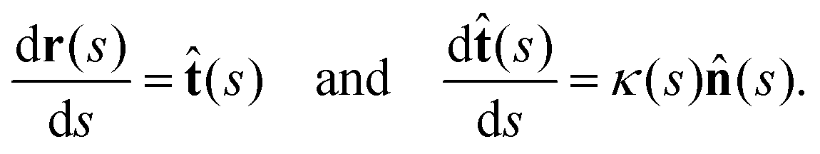 | (1) |
Let us define θ(s) to be the angle between the tangent vector at distance s and the x-axis, then κ(s) = dθ(s)/ds. For shape analysis, we translate and rotate each flagellum such that the basal end is at (0,0) and the orientation of the tangent vector at s = 0 is along the ![[x with combining circumflex]](https://www.rsc.org/images/entities/i_char_0078_0302.gif) -axis i.e. θ(s = 0,t) = 0. Following Stephens et al.,40 we performed principal mode analysis by calculating the covariance matrix of angles θ(s,t) defined as C(s,s′) = 〈(θ(s,t) − 〈θ〉)(θ(s′,t) − 〈θ〉)〉. The eigenvalues λn and the corresponding eigenvectors Vn(s) of the covariance matrix are given by
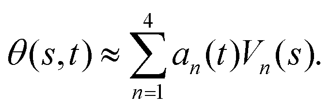
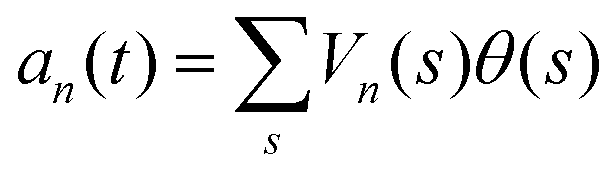
-axis i.e. θ(s = 0,t) = 0. Following Stephens et al.,40 we performed principal mode analysis by calculating the covariance matrix of angles θ(s,t) defined as C(s,s′) = 〈(θ(s,t) − 〈θ〉)(θ(s′,t) − 〈θ〉)〉. The eigenvalues λn and the corresponding eigenvectors Vn(s) of the covariance matrix are given by 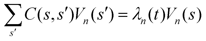 . We show that the superposition of four eigenvectors corresponding to four largest eigenvalues can describe the flagella's shape with high accuracy (see Fig. S2, ESI†):
 | (2) |
 . The fractional variance of flagella's shape captured by n eigenvectors is calculated as
  where
where  . Here N is the total number of eigenvectors. Fig. S2 (ESI†) shows that already two modes capture 96% and four modes capture 99% of the total variance.
2.4 Resistive force theory
As basal apparatus (BA) swims in a fluid, it generates flows of Reynolds number of the order of 10−3 or less. Thus, in the absence of inertia, the total force FBA and torque TBA is zero. The total force FBA includes friction forces acting on the basal body FBB as well as total hydrodynamics forces on both flagella: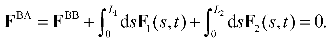 | (3) |
 | (4) |
| Fext + FBA = 0, Text + TBA = 0, | (5) |
 | (6) |
 | (7) |
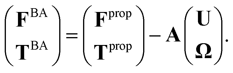
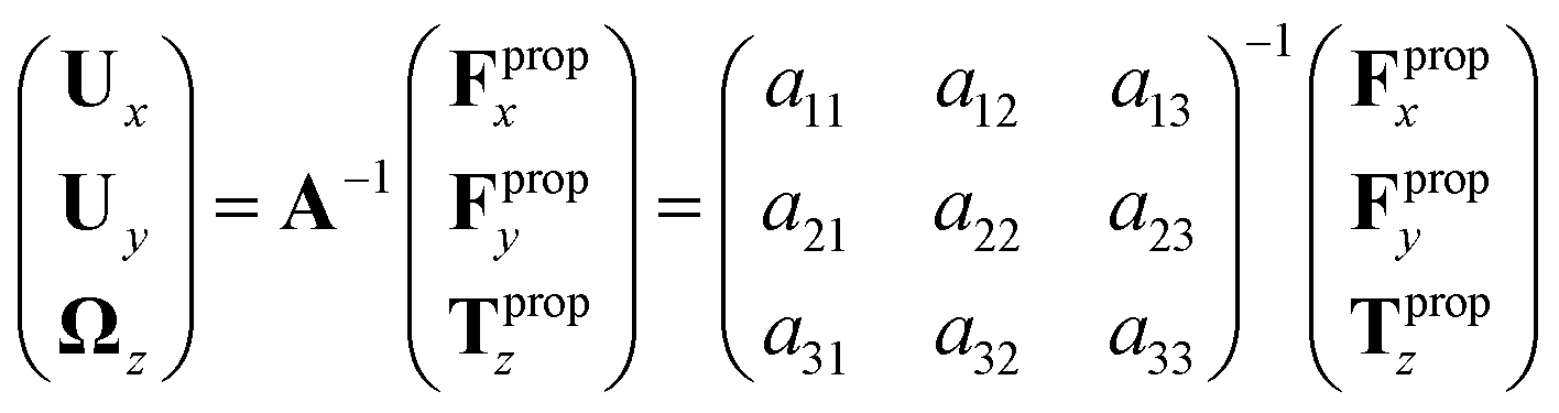
We determine the elements of drag matrix A by computing the propulsive force and torque exerted by fluid on the swimmer in the lab frame for a translating non-rotating and for a rotating non-translating basal apparatus.
To determine Fpropx, Fpropy and Tpropz which are propulsive forces and torque due to shape deformations of two flagella in body-fixed frame, we first define a reference frame which is fixed with respect to some arbitrary reference point in basal apparatus, namely the basal body. We set the origin of the body-fixed frame at basal body and define the local tangent vector of first flagellum at contour length s = 0 as ![[X with combining circumflex]](https://www.rsc.org/images/entities/i_char_0058_0302.gif) direction, the local normal vector
direction, the local normal vector ![[n with combining circumflex]](https://www.rsc.org/images/entities/i_char_006e_0302.gif) as Ŷ direction, and assume that ẑ and Ẑ are parallel. We let Φ(t) = θ(s = 0,t) to be the angle between and (see Fig. 2A), then in the laboratory frame the velocity of basal body, which was defined as the origin of the body-fixed frame, is given by:
as Ŷ direction, and assume that ẑ and Ẑ are parallel. We let Φ(t) = θ(s = 0,t) to be the angle between and (see Fig. 2A), then in the laboratory frame the velocity of basal body, which was defined as the origin of the body-fixed frame, is given by:
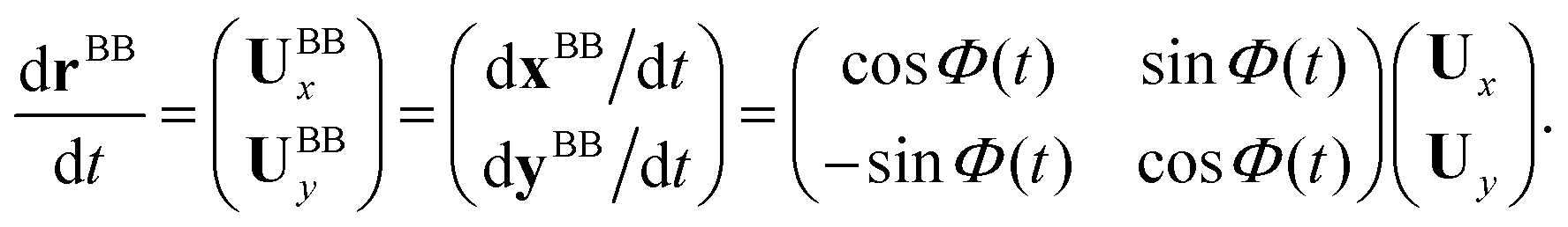 | (8) |
To calculate Fpropx, Fpropy and Tpropz for a given beating pattern of each flagellum in body-fixed frame, we used classical framework of resistive force theory (RFT) which neglects long-range hydrodynamic interactions between different parts of each flagellum as well as inter-flagella interactions. In this theory, each flagellum is divided to small cylindrical segments moving with velocity u′(s,t) in the body-fixed frame and the propulsive force Fprop is proportional to the local centerline velocity components of each segment in parallel and perpendicular directions:
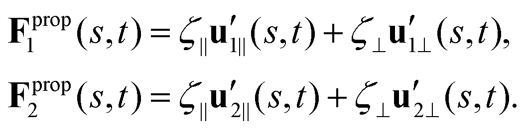 | (9) |
 and
and  are projections of the local velocity on the directions parallel and perpendicular to each flagellum, i.e.
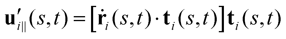 and
and 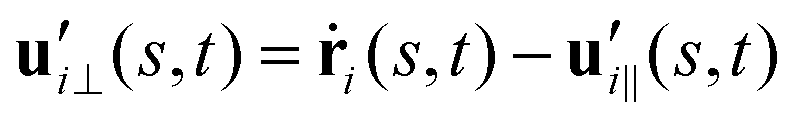 (i = 1, 2) where t1,2 are the unit tangent vectors along the first and second flagella. The friction coefficients ζ‖ and ζ⊥ for a thin filament of contour length L ∼ 10 μm and radius a ∼ 100 nm swimming in a surrounding fluid with viscosity μ = 0.96 pN ms μm−2 (water at 22 °C) are given by ζ‖ = 4πμ/(ln(2L/a) + 0.5) ∼ 2.1 pN ms μm−2 and ζ⊥ = 2ζ‖. This anisotropy indicates that to obtain the same velocity, one would need to apply a force in the perpendicular direction twice as large as that in the parallel direction.42 Furthermore, in the lab frame, the basal ends of both flagella move in synchrony with the basal body i.e.u1‖(s = 0,t) = u2‖(s = 0,t) = UBB‖ and u1⊥(s = 0,t) = u2⊥(s = 0,t) = UBB⊥.
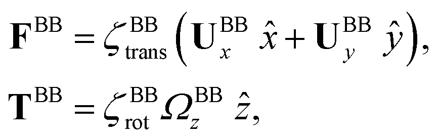
The effects of basal body connected to the basal ends of both flagella are accounted for by defining FBB and TBB in eqn (3) and (4) to be the drag force and torque acting on the basal body and are given as:
Here is a short summary of steps in our RFT analysis: first, we translate and rotate the basal apparatus such that basal body is at position (0,0) and the local tangent vector of first flagella at s = 0 and time t is in the direction defined by the tangent vector of first flagella at t = 0 and s = 0 (-axis in Fig. 2A). In this way, we lose the orientation information of the basal apparatus at all the time points except for the initial configuration at time t = 0. Note that the isolated flagellar apparatus maintains the V configuration characteristic of the apparatus in situ,27 therefore the angle of V-shape configuration at the basal ends of two flagella which changes over time is an input from our experimental data used for simulations. Second, we calculate the propulsive forces and torque in the body-frame using RFT and eqn (7) to obtain translational velocities Ux and Uy as well as rotational velocity Ωz of basal apparatus. Now the rotational matrix can be calculated as:
 | (10) |
3 Results
3.1 Wave form and beating frequencies
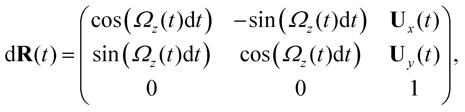
Fig. 1A illustrates the planar swimming motion of an isolated flagellar apparatus immersed in a water-like fluid supplemented with 2 mM ATP. If we define the posterior as the basal end of the apparatus, it swims forward as bending waves propagate from basal regions towards the distal tips (Fig. 1B and C). The flagella beat with a power stroke and a recovery stroke comparable to those observed in intact Chlamydomonas cells (see Fig. S3, ESI†). We tracked each flagellum separately using the GVF method (see Fig. 1D and Section 2.2) to characterize the curvature waves and beating frequencies (Fig. 1E and F). Traces of the distal ends of both flagella are shown in Fig. 1G. This method gives us x and y coordinates of N points along each flagellum which is used to calculate the angle between the local tangent vector and x-axis, θ(s,t) (see Fig. 2A).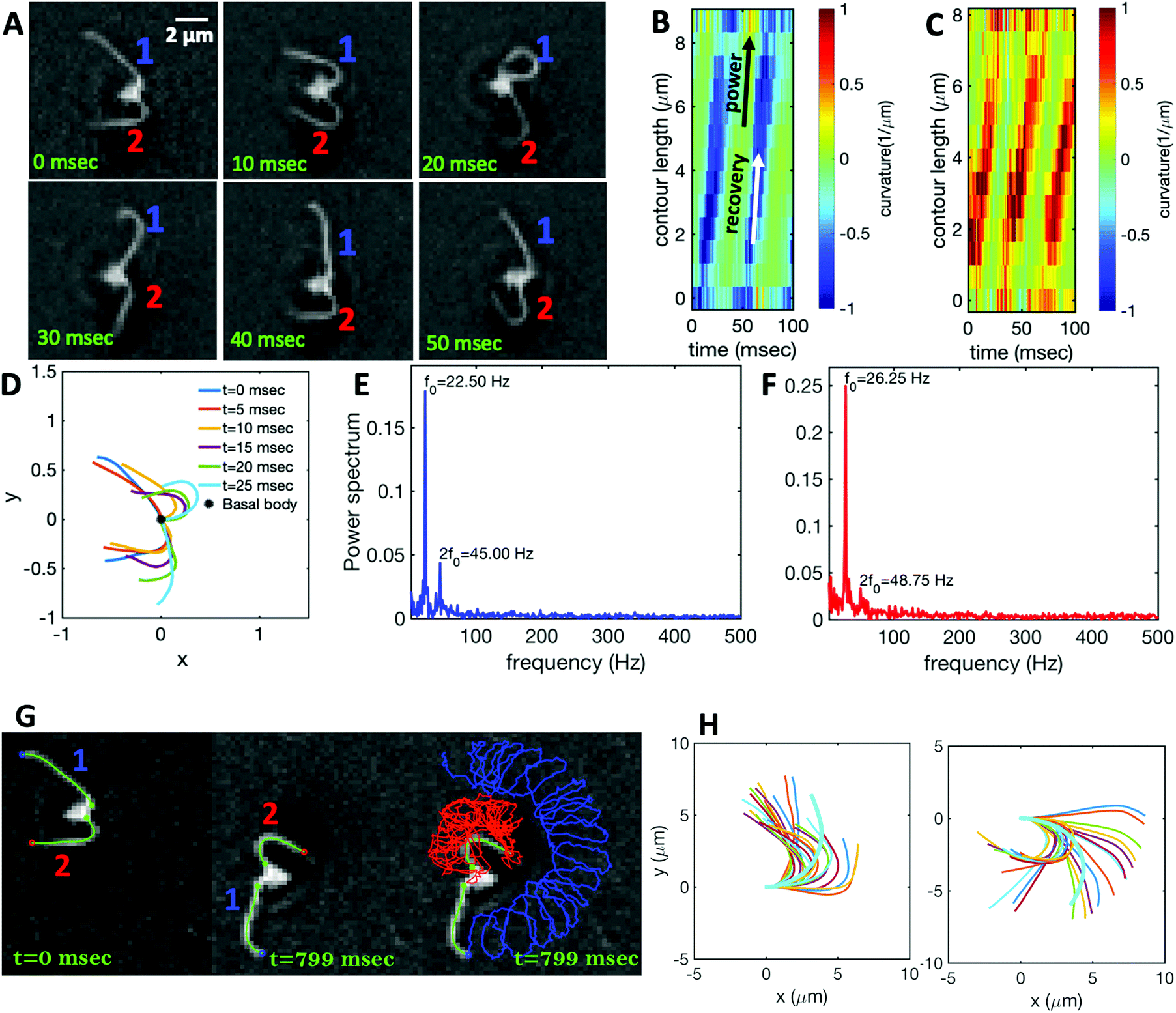 | ||
| Fig. 1 (A) Sample snapshots of swimming isolated flagellar apparatus. (B and C) Curvature waves propagating along the contour length of both flagella showing power and recovery strokes (see also Fig. S4, ESI†). (D) Representative flagellar waveforms, while basal body is translated to be at (0,0). (E and F) Power spectral density of both flagella showing that the first one beats at a frequency of 22.50 Hz, while the second one beats faster at a frequency of 26.25 Hz. (G) Swimming flagellar apparatus shown at two different time points. Both flagella are tracked using the GVF method. Trajectories of distal ends of both flagella as it swims in a time interval of 0 to 799 ms are shown in the last panel. (H) The basal ends of tracked filaments of both flagella are translated to position (0,0) and rotated such that the tangent vector at s = 0 is along the x-axis. Semi-circular arcs in cyan color with mean curvatures of κ0 ∼ 0.285 μm−1 and 0.268 μm−1 show the time-averaged shape of flagellum 1 and 2, respectively. This averaged intrinsic curvature makes the waveform asymmetric (see Video S1, ESI†). | ||
 | ||
| Fig. 2 (A) Definition of laboratory axes x, y and body-fixed axes X, Y. (B) Wiggling movement of the basal body on a helical trajectory as it swims with its two flagella in the vicinity of a substrate. (C) Displacements of basal body xBB and yBB relative to the original position at t = 0 showing small-scale oscillations with a frequency of 21.28 Hz (beating frequency of flagella) embedded in large-scale oscillations of frequency around 0.63 Hz. The dashed lines in magenta highlight the first 800 frames that are used for tracking in Fig. 1. (D) Power spectrum of xBB and yBB displays clear peaks at two frequencies of 21.28 and 0.63 Hz (see Video S2, ESI†). | ||
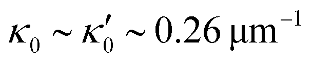
We quantified the curvature waves propagating along the contour length of each flagellum using tangent angle θ(s,t) (Fig. 1B and C). FFT analysis of curvature waves shows dominant peaks at 22.50 Hz and 26.25 Hz for first and second flagellum, respectively (Fig. 1E and F). This is smaller than the typical beating frequencies of flagella in intact wall-less mutants of Chlamydomonas cells (see Fig. S3, ESI†). We also observed clear peaks at the second harmonics (45 Hz and 48.75 Hz) which temporally break the mirror symmetry of beating patterns.44 Interestingly, the oscillatory pattern of each flagellum exhibits a pronounced asymmetry, corresponding to a constant static curvature.45,46 We calculated the time-averaged shape of each flagellum which results in a semi-circular arc with an intrinsic curvature of κ0 ∼ π/L ∼ 0.24 rad μm−1. Here L ∼ 10 μm is the contour length of the flagellum (see Fig. 1H). This value of κ0 is comparable to the results reported for axonemes isolated from wild type C. reinhardti cells,46 as well as our analysis of mean curvature of flagella in intact wall-less C. reinhardti cells (see Fig. S3, ESI†).
As the flagellar apparatus swims, the basal body follows a helical path as displayed in Fig. 2B. The basal body trajectory shows a wiggle with a frequency of 21 Hz embedded in large-scale oscillations with much smaller frequency of 0.63 Hz (Fig. 2C and D). Note that a flagellar apparatus with two flagella beating exactly at the same wave amplitude, frequency and phase, swims in a straight path. However, variations in these parameters generate torque causing the basal apparatus to swim in a circular path (see Section 3.3). Even if two flagella beat at the same frequencies, the phase and amplitude of curvature waves are dynamic variables, so the swimmer moving on a curved path does not return precisely to its initial position and follows a helical trajectory.
3.2 Mode analysis of flagellar shape and phase dynamics
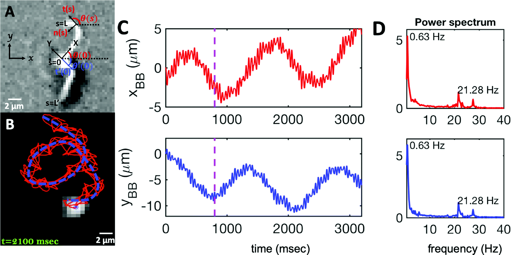
We performed principal mode analysis to describe the time-dependent shape of both flagella in swimming apparatus. This analysis is based on the method introduced by Stephens et al.,40 which was initially used to characterize wave forms in C. elegans. We used x and y coordinates of each tracked flagellum, obtained using the GVF technique38,39 (see Section 2.2), to calculate θ(s,t) which is the angle between the local tangent vector of tracked flagellum center line and-axis (see Fig. 2A). Next, we computed the covariance matrix C(s,s′) of fluctuations in angle θ(s,t) for each flagellum separately. Fig. 3A shows the color map of the covariance matrix of the first flagellum which has an effective reduced dimensionality with only a small number of non-zero eigenvalues. Remarkably, only four eigenvectors Vn(s) (n = 1,…, 4) corresponding to the first four largest eigenvalues of C(s,s′) capture the flagellum's shape with high accuracy (see Video S3, ESI†). These four eigenvectors are plotted in Fig. 3B and the first two time-dependent motion amplitudes a1(t) and a2(t) are presented in Fig. 3E. Note that the first two modes, which capture 96% of the total variation (see Fig. S2, ESI†), resemble cosine and sine functions that are in quadrature, and that these first two modes correspond to the lowest frequency behavior in our system, while higher modes correspond to higher harmonics.
 | ||
| Fig. 3 Mode analysis of first flagellum of basal apparatus. (A) The covariance matrix C(s,s′) of fluctuations in angle θ(s,t). (B) Four eigenvectors corresponding to four largest eigenvalues of matrix C(s,s′). (C) Probability density of the first two shape amplitudes P(a1(t),a2(t)). The phase angle is defined as ϕ(t) = atan2(a2(t),a1(t)). (D) Superposition of four eigenmodes presented in part B with coefficients a1(t) to a4(t) can reproduce the shape of flagella with high accuracy (see Fig. S2, ESI†). (E) Time evolution of the first two dominant shape amplitudes a1(t) and a2(t) showing regular oscillations of frequency 22.50 Hz. (F) Dynamics of the phase ϕ(t) shows a linear growth, indicating steady rotation in the a1 − a2 plane presented in part C. We note that dϕ/dt = 2πf0, where f0 is the beating frequency. | ||
The Fourier analysis of oscillating motion amplitudes a1(t) and a2(t) gives clear peaks at 22.50 Hz for first flagellum and 26.25 Hz for the second one. Fig. 1E and F also show the existence of higher harmonics at 45 Hz and 48.75 Hz, respectively. Furthermore, the probability density distribution of a1(t) and a2(t) (Fig. 3C) demonstrates that on average, the principal modes follow a closed trajectory reminiscent of a stable limit cycle, and can be used to define an instantaneous phase as ϕ(t) = atan2(a2(t),a1(t)). The phase ϕ maps variables a1(t) and a2(t) undergoing non-linear oscillations (Fig. 3E) to a new variable which linearly increases over the beating period of each flagellum. By working in phase space, we simply assume that, to leading order, the perturbation due to mechanical coupling via the basal body affects only the phase and not the amplitude of the flagella as a non-linear oscillator. Fig. 3F shows the time-dependent phase calculated for first flagellum which is (on average) a monotonically increasing function of time and is equivalent to a uniform rotation in the phase space defined in the a1 − a2 plane (Fig. 3C). The time derivative of phase ϕ(t) is a measure of the oscillation frequency f0.
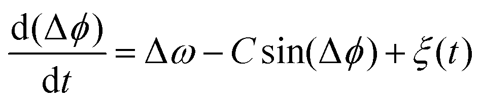
The phase dynamics of each flagellum is composed of non-linear fluctuations around a linear deterministic time trend (Fig. 4A). If the two flagella were independent non-interacting oscillators, we would expect the phase difference to grow linearly at a rate proportional to the frequency mismatch Δf (Fig. 4B), and besides some minor fluctuations, this is what we see – i.e. we find no evidence of phase locking and synchronization. Fig. 4D illustrates the deviation of the phase from the linear component obtained by subtracting the unwrapped phase of each flagellum plotted in Fig. 4A, from the corresponding linear component presented in Fig. 4C. The power spectrum of fluctuations of first flagellum gives clear peaks at 22.50 Hz and higher harmonics, as shown in Fig. 4E, similarly for the second flagellum.
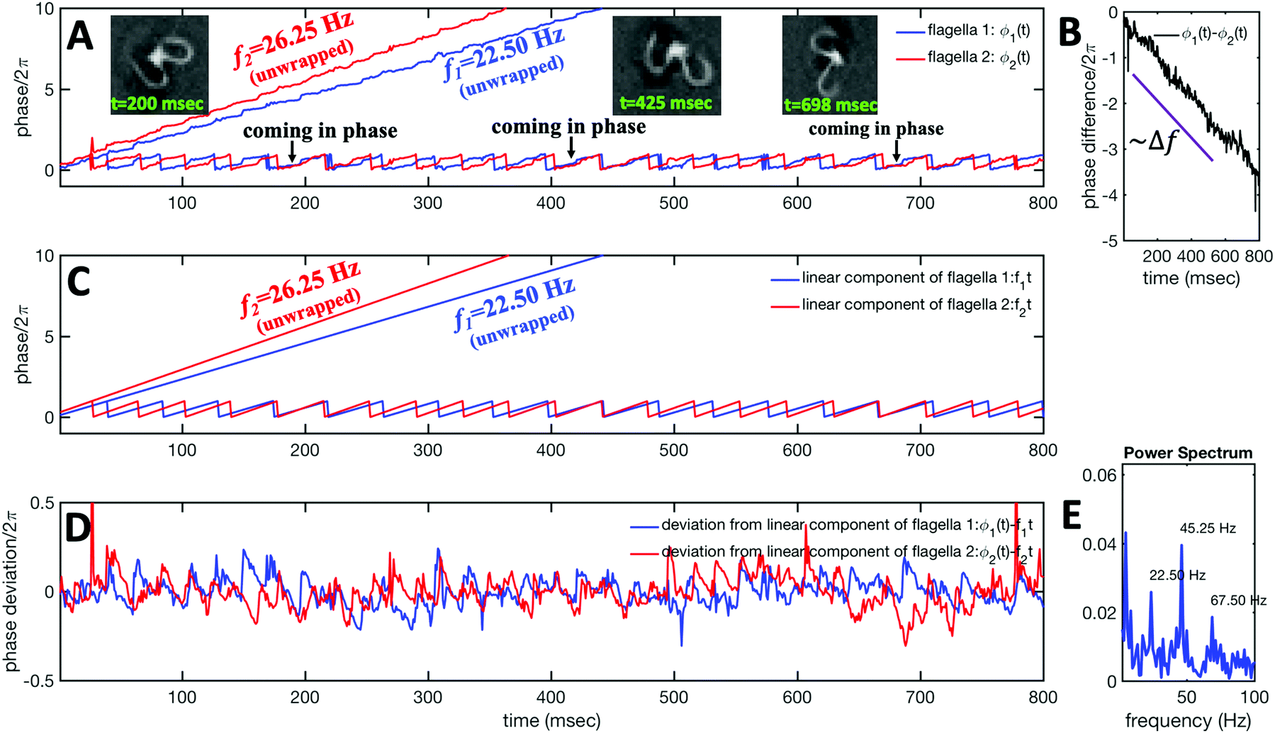 | ||
| Fig. 4 Phase dynamics of two mechanically coupled flagella in swimming basal apparatus. (A) For each flagellum, we extract a time-dependent phase ϕ(t) from motion amplitudes a1(t) and a2(t) defined as ϕ(t) = atan2(a1(t),a2(t)). Unwrapped phase for each flagellum shows fluctuations around a linear trend. (B) For a frequency mismatch of 3.75 Hz (15% of the mean), the two flagella display phase differences that vary monotonously with time. (C) Linear phase component of each flagellum that scales with frequency. (D) Deviations from linear components where the unwrapped phase of two flagella in part A is subtracted from the corresponding unwrapped linear components presented in part C. (E) Power spectrum of non-linear fluctuations of the first flagellum showing clear peaks at beating frequency of 22.50 Hz and at higher harmonics. | ||
Obviously, mechanical coupling fails to entrain two flagella and on average, they behave as two isolated oscillators with phase evolving at constant rates ω1 = 2πf1 and ω2 = 2πf2 in time. As two flagella beat with 3.75 Hz frequency difference, over time they find similar phase values (black arrows in Fig. 4A), corresponding to the time points that two flagella for a short time beat in synchrony. The frequency difference quickly drives the system out of the synchronous state to the asynchronous phase, which is the dominant state during the swimming period of flagellar apparatus (see Video S1 and Fig. S5 for a similar analysis of another exemplary basal apparatus, ESI†).
A generic description of synchronization in pairs of coupled oscillators in the presence of noise is provided by the stochastic Adler equation:13,19,21
 | (11) |
![[thin space (1/6-em)]](https://www.rsc.org/images/entities/char_2009.gif) cos(Δϕ). The intrinsic frequency difference Δω corresponds to a global tilt in this potential. If the frequency mismatch between two oscillators becomes larger than the coupling strength (Δω > |C|), then Adler equation does not have a steady state solution (see Fig. S5F, ESI†). Thus, synchronization cannot occur corresponding to the case of a phase drift where the phase difference depends linearly on time with a slope given by the frequency mismatch Δω.12,13,19 Fluctuations around this linear trend, as shown in Fig. 4B, directly gives a measure of the effective temperature Teff. In this case, the coupling strength C, which includes the effect of hydrodynamic interactions, mechanical coupling and swimmer movement, is much smaller than Δω and cannot be estimated.12 For our experiment presented in Fig. 1 with Δω = 2πΔf = 23.56 Hz and mean frequency of 〈ω〉 = 2π〈f〉 = 153.12 Hz, an upper bound of
cos(Δϕ). The intrinsic frequency difference Δω corresponds to a global tilt in this potential. If the frequency mismatch between two oscillators becomes larger than the coupling strength (Δω > |C|), then Adler equation does not have a steady state solution (see Fig. S5F, ESI†). Thus, synchronization cannot occur corresponding to the case of a phase drift where the phase difference depends linearly on time with a slope given by the frequency mismatch Δω.12,13,19 Fluctuations around this linear trend, as shown in Fig. 4B, directly gives a measure of the effective temperature Teff. In this case, the coupling strength C, which includes the effect of hydrodynamic interactions, mechanical coupling and swimmer movement, is much smaller than Δω and cannot be estimated.12 For our experiment presented in Fig. 1 with Δω = 2πΔf = 23.56 Hz and mean frequency of 〈ω〉 = 2π〈f〉 = 153.12 Hz, an upper bound of 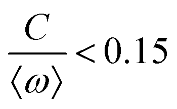 for the coupling strength can be estimated.
3.3 Quantitative agreement with resistive force theory
We used the experimental beating patterns of the flagellar apparatus to examine the validity of resistive force theory in our in vitro model system. At each time point t, the configuration of flagellar apparatus in the lab frame was calculated from instantaneous translational and rotational velocities of flagellar apparatus in the body-fixed frame using the rotation matrix presented in eqn (10). The control parameter was the drag anisotropy ζ⊥/ζ‖ which is the ratio between drag coefficients in perpendicular and tangential directions. Given experimental wave forms, we compared RFT simulations with instantaneous translational and rotational velocities of flagellar apparatus in the body-fixed frame (see Fig. 5 and 6). We found a quantitative agreement for drag anisotropy of ζ⊥/ζ‖ = 2. Note that in the body-fixed frame, the motion of basal body is described by time-dependent translational velocities Ux, Uy and rotational velocity Ωz which is a measure of rotation of the basal apparatus. In the lab frame, the translational velocities of the basal body are given by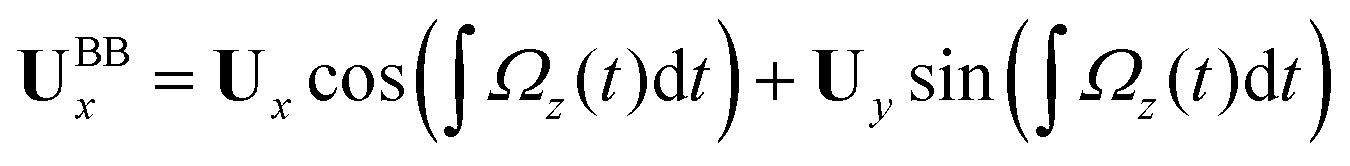 and
and  . Fig. 6 shows Ux, Uy and Ωz obtained from RFT analysis and a comparison with direct experimental measurements in the body-fixed frame, computed by first differentiating experimental xBB, yBB and θ(s = 0) with respect to time and then transforming to the swimmer-fixed frame. Remarkably, the corresponding power spectra of Ux, Uy and Ωz show dominant peaks at 22.50 Hz indicating that the beating frequency of the first flagellum is reflected in translational and rotational velocities of the basal body.
 | ||
| Fig. 5 RFT simulations using experimental beating patterns. (A) Initial configuration of flagellar apparatus at t = 0 extracted from experimental data (compare with Fig. 1G at t = 0). (B–D) Swimming trajectory of flagellar apparatus obtained by RFT simulations. (E and F) Dimensionless positions xBB and yBB of the basal body obtained from RFT, display oscillations reflecting the beating frequency of flagella. Lengths are non-dimensionalized to the contour length of flagella (see Video S4, ESI†). | ||
 | ||
| Fig. 6 Comparison between RFT analysis and experiments with ζ⊥/ζ‖ = 2. (A–C) Instantaneous translational and rotational velocities of basal apparatus Ux, Uy and Ωz(t) in body-fixed frame, obtained from RFT simulations using experimental beating patterns. Direct experimental results are shown in magenta. Power spectra of translational and angular velocities show clear peaks around 22.50 Hz, which is the beating frequency of the first flagellum. | ||
 | (12) |
 is determined from experimental data by characterizing the time-averaged shape of each flagellum, as illustrated in Fig. 1H. Furthermore, κ1 and
  are the amplitudes of the dynamic modes which are estimated from experimental wave patterns to be around 0.45 μm−1. The negative signs in terms f1t and f2t generate curvature waves that propagate from basal regions (s = 0) towards the distal tips (s = L), as observed experimentally. Two flagella are positioned exactly symmetrically with respect to the axis of symmetry of the basal apparatus and in our simulations, we assume the V-junction angle to be fixed at 180°. To perform simulations, we compute the drag force density felt by each flagellum in the framework of resistive-force theory (see eqn (9)). The basal body is assumed to have a dimensionless radius of 0.1.
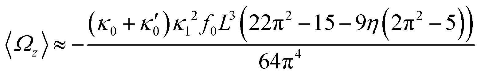
In general, the mean rotational velocity 〈Ωz〉 of flagellar apparatus depends on the amplitudes of static and dynamic modes as well as the frequency and phase difference between the two flagella. For a single flagellum beating at frequency f0, in the small-curvature approximation assuming κ0L/(2π) and κ1L/(2π) to be small, 〈Ωz〉 depends linearly on κ0 but is proportional to the square of κ1 (see Appendix I, ESI† and ref. 44 and 47):
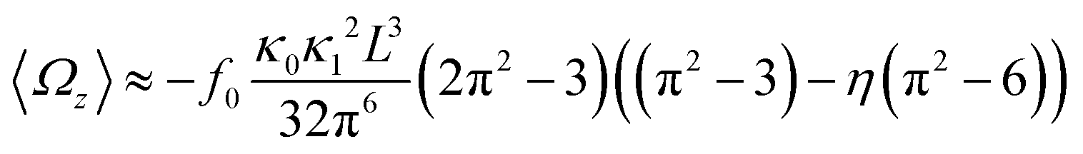 | (13) |
In the case of flagellar apparatus with two flagella, ignoring the hydrodynamic drag force of the basal body for simplicity, rotational velocity has contribution from both flagella (see Appendix I, ESI†):
 | (14) |
 and
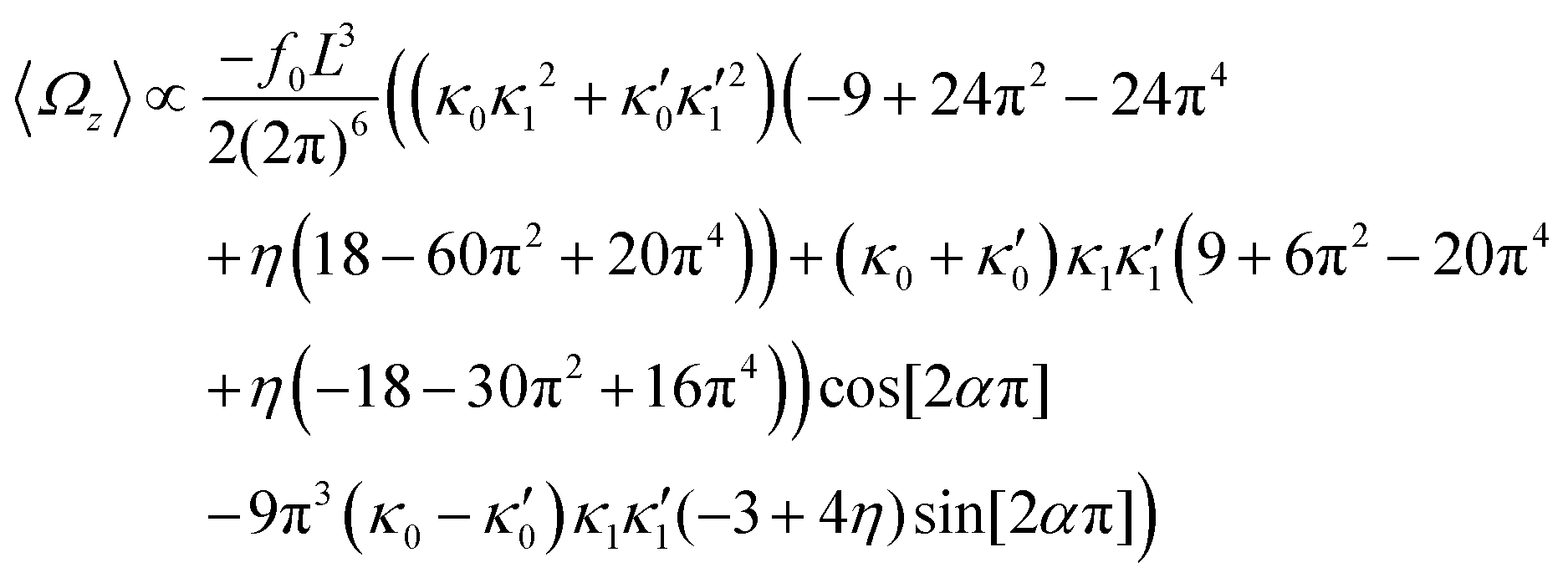
and  , where the two flagella waveforms are mirror images having same parameters with only a phase difference between them, eqn (14) simplifies to:
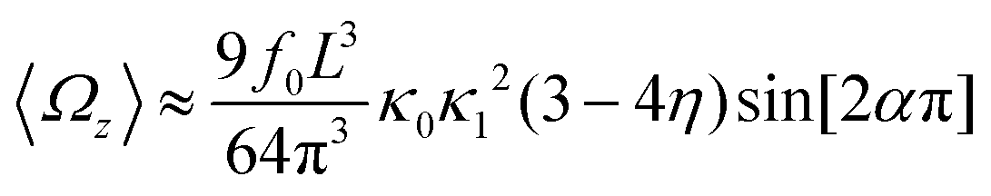 | (15) |
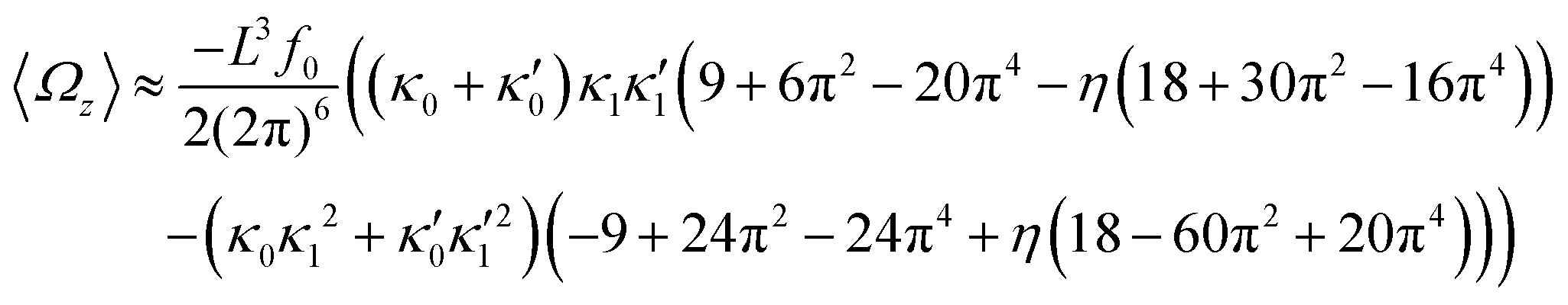 | (16) |
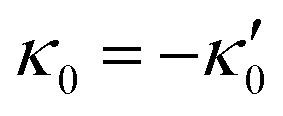
We comment on some properties of eqn (14)–(16): flagellar apparatus with two flagella beating exactly at the same frequency and phase, with mirror-symmetric waveforms ( and
and 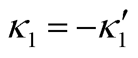 ), will swim in a straight path with its translational velocity Uy oscillating at frequency of flagellar beat (Fig. 7A and D). However, only a phase difference between two flagella is enough to change the swimming trajectory to a circular path (Fig. 7B, C, E and F). It is noteworthy that the mean rotational velocity 〈Ωz〉 scales with sin(2πα) and thereby, by increasing the phase difference in the range 0 ≤ 2πα ≤ π/2, the swimmer rotates on average faster as illustrated in Fig. 7C. At a phase difference between π/2 ≤ 2πα ≤ π, 〈Ωz〉 starts to decrease and vanishes at π (α = 1/2) (see eqn (15)). Furthermore, a frequency difference between two flagella also generates a circular swimming path. This is shown in Fig. 8A, where two flagella beat at 50 Hz (red trajectory) and 56 Hz (blue trajectory), while all the other parameters are kept the same. Since in our analytical approximation, to calculate the time-averaged Ωz, we consider only one single frequency f0 (see eqn (S14), ESI†); the influence of having two different beating frequencies is not reflected in our expression in eqn (14). Another point to mention is that the amplitude of dynamic mode enters as κ12 and
  in the eqn (16) and by introducing a small difference in values of κ1 and
  , we can switch the swimming direction. Fig. 8B shows an example of a flagellar apparatus where the flagellum with red trace has a smaller frequency but larger amplitude of the dynamics mode κ1, while the other flagellum with blue trace has larger frequency but smaller
  . Thus, the flagellum with larger κ1 wins and sets the sign of 〈Ωz〉. Remarkably, if the beating frequency, amplitude of dynamic mode and phase are equal for both flagella (
 and α = 0), then Ωz is proportional to
  :
:
 | (17) |
 | ||
Fig. 7 Simulations in the framework of RFT with a simplified wave pattern formed of superposition of a static and a dynamics mode. All parameters are the same for both flagella except the phase shift 2πα. (A) Unsteady straight swimming for a flagellar apparatus with α = 0. The only non-zero component of velocity is Uy which oscillates over time and there is no rotation. (B) Circular swimming path for swimmer with α = 1/8 and (C) α = 1/4. The mean rotational velocity is higher for a larger phase shift. (D–F) Instantaneous translational and rotational velocities in body-fixed frame corresponding to parts A, B and C, respectively. Note that both Ux, Uy and Ωz oscillate at a flagellar beat frequency of 50 Hz. Other parameters are:  , ,  , and , and  . Note that the parameters with prime are for flagella with blue trajectory (see Videos 5–7, ESI†). . Note that the parameters with prime are for flagella with blue trajectory (see Videos 5–7, ESI†). | ||
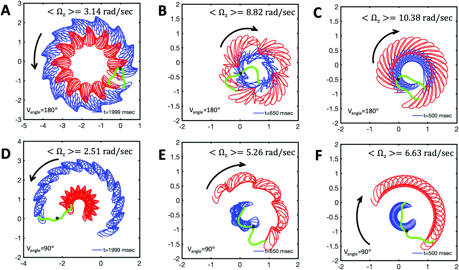 | ||
Fig. 8 Simulations with simplified wave patterns to study the influence of variations in frequency and amplitude of the dynamic mode κ1. (A) Flagella with blue trace beats faster compared to the flagellum with red trace (56 Hz versus 50 Hz) and therefore it sets the sign of 〈Ωz〉. (B) To switch the direction of rotation, the slower beating flagellum should beat with larger wave amplitude κ1. (C) Keeping the frequencies and intrinsic curvature similar, flagellum with larger κ1 (red trace) sets the direction of swimming. Parameters are 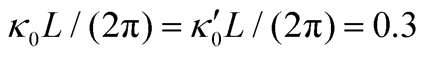 , V-junction angle = 180°, α = 0 for all simulations, and (A) f0 = 50 Hz, , V-junction angle = 180°, α = 0 for all simulations, and (A) f0 = 50 Hz, 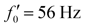 , ,  , (B) f0 = 50 Hz, , (B) f0 = 50 Hz,  , κ1L/(2π) = 0.7, , κ1L/(2π) = 0.7, 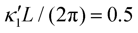 , (C) f0 = 50 Hz, , (C) f0 = 50 Hz, 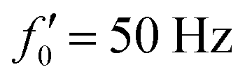 , κ1L/(2π) = 0.7, , κ1L/(2π) = 0.7,  . (D–F) Simulations in parts A–C are repeated with a V-junction angle of 90°. Parameters with prime are for flagella with blue trajectory (see Videos S8–S13, ESI†). . (D–F) Simulations in parts A–C are repeated with a V-junction angle of 90°. Parameters with prime are for flagella with blue trajectory (see Videos S8–S13, ESI†). | ||
3.4 Discussion
In this paper, we have used high-speed imaging, quantitative image processing, and mode analysis to study the wave dynamics of flagellar apparatus isolated from wall-less strain of C. reinhardtii. For isolation of this unique in vitro system, we followed the protocol established by Hyams and Borisy,35,36 which has a very low yield; only 2–3% of the cells release their flagellar apparatus. In contrast to the results reported in ref. 35 and 36, all of the isolated apparatus in our experiments (N = 10) had an intrinsic frequency mismatch of Δf = 3.73 ± 1.84 Hz (∼10–41% of the mean) and therefore, it was not possible with our data to investigate the synchronization dynamics in swimmers with no or very small frequency differences. Table S1 in the ESI† presents a summary of frequencies of these 10 basal apparatus. In contrast to previous studies12,13,26,29 investigating the synchronization dynamics in micropipette-fixed cells, we focused on freely swimming basal apparatus with an intrinsic interflagellar frequency difference of Δf ∼ 3.75 Hz (∼15% of the mean). In the presence of such a high frequency mismatch, neither rotational motion of the swimmer caused by asynchronous beating of two flagella nor coupling between two flagella either via elastic fibers connecting the basal bodies or interflagellar hydrodynamic interactions are strong enough to overcome the high frequency mismatch and the effect of noise (which acts against synchronization) to entrain two flagella. This is in agreement with experimental observations of asynchronous flagellar beats in intact C. reinhardtii cells with a high interflagellar frequency difference (10–30%),12,31,51 supporting the hypothesis that intrinsic frequencies of flagella are probably controlled by signaling processes inside the cell.We tracked the waveforms of each flagellum using the GVF technique38,39 with high spatio-temporal resolution, allowing us to characterize the bending waves that propagate from basal ends towards the distal tips at a frequency of 25 ± 4 Hz. We performed mode analysis of flagella exhibiting rhythmic patterns40 to define a continuous phase for each oscillator flagellum. The phase analysis captures the dynamics of two interacting flagella in basal apparatus, confirming that they effectively act as two isolated pendulums perturbing each other by non-linear fluctuations, but no entrainment can occur and interflagellar phase difference grows linearly over time with a temporal slope of Δf.19,26
We used our tracked data to examine the validity of resistive force theory for flagellar apparatus swimming effectively in 2D. From experimental recorded videos, we extracted the position of the basal body with sub-micron resolution and calculated the translational and rotational velocities. It is to be noted that as flagellar apparatus swims, the angle of the V junction changes over time (see Videos S1 and S2, ESI†). We computed the instantaneous V-angle from the tracked data and used it as an experimental input for our RFT analysis. Comparing our experimental data with instantaneous translational and rotational velocities of basal apparatus obtained by RFT simulations, we found a quantitative agreement with a drag anisotropy of 2. Originally, the ratio ζ⊥/ζ‖ = 2 was used by Gray and Hancock for sea-urchin spermatozoa swimming far away from the boundary.52 In our experiments, the flagellar apparatus swims in the vicinity of a glass surface and in this respect, our system is similar to experiments with microtubules moving parallel to a kinesin-coated substrate which can exert forces on microtubules.53
To investigate the swimming dynamics, we performed simulations and analytical approximations using simplified wave forms, allowing us to estimate the mean rotational velocity of flagellar apparatus in the limit of small intrinsic curvature and wave amplitude. To calculate the forces excreted by the fluid on cylindrical segments of each flagellum we used RFT which ignores long-range hydrodynamic interactions between different parts of the flagella. Interestingly, our analysis demonstrates that by introducing a phase or frequency difference between two flagella, steering of flagellar apparatus can occur.
The results presented in this study are focused on the examples where the basal apparatus swims effectively in 2D in the vicinity of the substrate. This greatly facilitates the tracking of flagella and data analysis. However, we observed several examples (N = 8) where basal apparatus swims in 3D and undergoes tumbling motion, as shown in the Videos S16 and S17 (ESI†). This out of plane swimming dynamics complicates the tracking process of two flagella. In future studies, 3D microscopy techniques54 are necessary to capture the full swimming dynamics of basal apparatus. In addition, we observed often in our experiments basal apparatus with only one beating flagellum while the second one is either not active or the activity is very low (see Videos S18–S20, ESI†). Therefore, not all isolated basal apparatus are suitable for synchronization analysis, which further reduces the yield of the experiments. Furthermore, we emphasize that our experiments are performed with one specific strain of Chlamydomonas cells and experiments with other strains are necessary to check the generality of our results on synchronization dynamics.
It would be worthwhile to extend our analysis to flagellar apparatus without intrinsic frequency mismatch as experimentally observed in ref. 35 and 36. Lastly, Hyams and Borisy reported interesting observations of switching the swimming direction of basal apparatus from forward to backward motion at calcium concentrations above 1 μM. In our experiments, under standard reactivation conditions, only forward swimming motion was observed. Calcium ions presumably affect the form and direction of ciliary beating patterns and it is known that exchange of calcium ions is crucial for tactic behavior of C. reinhardtii cells.36,55 Investigations in this direction are under way in our laboratory.
Author contributions
A. G. designed the research. A. G. and S. G. P. performed the experiments. A. B. wrote the Matlab code for GVF algorithm. S. G. P. did the tracking of the flagellar apparatus. A. G. and A. B. performed RFT analysis, simulations and analytical calculations. A. G. wrote the first draft of the manuscript and all the authors contributed to the discussions and the final version of the manuscript.Conflicts of interest
There are no conflicts to declare.Acknowledgements
We are grateful to E. Bodenschatz, K. Wan, R. Ahmad, and A. Zaben for valuable discussions and unknown referees for helpful comments. We also thank S. Romanowsky, M. Müller and K. Gunkel for technical assistance. A. G. and A. B. acknowledge MaxSynBio Consortium, which is jointly funded by the Federal Ministry of Education and Research of Germany and the Max Planck Society. The authors also acknowledge M. Lorenz, S. Bank and the Göttingen Algae Culture Collection (SAG) for providing the Chlamydomonas reinhardtii wall-less strain SAG 83.81. Open Access funding provided by the Max Planck Society.Notes and references
- J. T. Eggenschwiler and K. V. Anderson, Annu. Rev. Cell Dev. Biol., 2007, 23, 345–373 CrossRef CAS.
- W. F. Marshall and S. Nonaka, Curr. Biol., 2006, 16, R604–R614 CrossRef CAS.
- J. G. Goetz, E. Steed, R. R. Ferreira, S. Roth, C. Ramspacher, F. Boselli, G. Charvin, M. Liebling, C. Wyart and Y. Schwab, et al. , Cell Rep., 2014, 6, 799–808 CrossRef CAS.
- H. Machemer, J. Exp. Biol., 1972, 57, 239–259 CAS.
- R. E. Goldstein, Annu. Rev. Fluid Mech., 2015, 47, 343–375 CrossRef.
- W. Gilpin, M. S. Bull and M. Prakash, Nat. Rev. Phys., 2020, 1–15 Search PubMed.
- R. Faubel, C. Westendorf, E. Bodenschatz and G. Eichele, Science, 2016, 353, 176–178 CrossRef CAS.
- A. G. Kramer-Zucker, F. Olale, C. J. Haycraft, B. K. Yoder, A. F. Schier and I. A. Drummond, Development, 2005, 132, 1907–1921 CrossRef CAS.
- T. Mitchison and H. Mitchison, Nature, 2010, 463, 308–309 CrossRef CAS.
- S. A. Burgess, M. L. Walker, H. Sakakibara, P. J. Knight and K. Oiwa, Nature, 2003, 421, 715–718 CrossRef CAS.
- T. Ishikawa, H. Sakakibara and K. Oiwa, J. Mol. Biol., 2007, 368, 1249–1258 CrossRef CAS.
- M. Polin, I. Tuval, K. Drescher, J. P. Gollub and R. E. Goldstein, Science, 2009, 325, 487–490 CrossRef CAS.
- R. E. Goldstein, M. Polin and I. Tuval, Phys. Rev. Lett., 2009, 103, 168103 CrossRef.
- G. I. Taylor, Proc. R. Soc. London, Ser. A, 1951, 209, 447–461 Search PubMed.
- N. Uchida and R. Golestanian, Phys. Rev. Lett., 2011, 106, 058104 CrossRef.
- R. Golestanian, J. M. Yeomans and N. Uchida, Soft Matter, 2011, 7, 3074–3082 RSC.
- A. Vilfan and F. Jülicher, Phys. Rev. Lett., 2006, 96, 058102 CrossRef.
- E. Lauga and T. R. Powers, Rep. Prog. Phys., 2009, 72, 096601 CrossRef.
- B. Friedrich, Eur. Phys. J.: Spec. Top., 2016, 225, 2353–2368 Search PubMed.
- R. R. Bennett and R. Golestanian, Phys. Rev. Lett., 2013, 110, 148102 CrossRef.
- R. Adler, Proc. IRE, 1946, 34, 351–357 Search PubMed.
- D. R. Brumley, K. Y. Wan, M. Polin and R. E. Goldstein, eLife, 2014, 3, e02750 CrossRef.
- G. Quaranta, M.-E. Aubin-Tam and D. Tam, Phys. Rev. Lett., 2015, 115, 238101 CrossRef.
- V. F. Geyer, F. Jülicher, J. Howard and B. M. Friedrich, Proc. Natl. Acad. Sci. U. S. A., 2013, 110, 18058–18063 CrossRef CAS.
- B. M. Friedrich and F. Jülicher, Phys. Rev. Lett., 2012, 109, 138102 CrossRef.
- K. Y. Wan, K. C. Leptos and R. E. Goldstein, J. R. Soc., Interface, 2014, 11, 20131160 CrossRef.
- D. L. Ringo, J. Cell Biol., 1967, 33, 543–571 CrossRef CAS.
- K.-F. Lechtreck and M. Melkonian, The Cytoskeleton of Flagellate and Ciliate Protists, Springer, 1991, pp. 38–44 Search PubMed.
- K. Y. Wan and R. E. Goldstein, Proc. Natl. Acad. Sci. U. S. A., 2016, 113, E2784–E2793 CrossRef CAS.
- E. H. Harris, Annu. Rev. Plant Biol., 2001, 52, 363–406 CrossRef CAS.
- U. Rüffer and W. Nultsch, Cell Motil., 1985, 5, 251–263 CrossRef.
- M. Sleigh, Nature, 1979, 277, 263–264 CrossRef CAS.
- G. S. Klindt, C. Ruloff, C. Wagner and B. M. Friedrich, New J. Phys., 2017, 19, 113052 CrossRef.
- K. Polotzek and B. M. Friedrich, New J. Phys., 2013, 15, 045005 CrossRef.
- J. S. Hyams and G. G. Borisy, Science, 1975, 189, 891–893 CrossRef CAS.
- J. S. Hyams and G. G. Borisy, J. Cell Sci., 1978, 33, 235–253 CAS.
- V. Geyer, PhD thesis, Sächsische Landesbibliothek-Staats-und Universitätsbibliothek Dresden, 2013.
- C. Xu and J. L. Prince, IEEE Proc. CVPR, 1997, pp. 66–71 Search PubMed.
- C. Xu and J. L. Prince, et al. , IEEE Trans. Image Proc., 1998, 7, 359–369 CrossRef CAS.
- G. J. Stephens, B. Johnson-Kerner, W. Bialek and W. S. Ryu, PLoS Comput. Biol., 2008, 4, e1000028 CrossRef.
- J. B. Keller and S. Rubinow, Biophys. J., 1976, 16, 151–170 CrossRef CAS.
- R. Johnson and C. Brokaw, Biophys. J., 1979, 25, 113–127 CrossRef CAS.
- J. Leach, H. Mushfique, S. Keen, R. Di Leonardo, G. Ruocco, J. Cooper and M. Padgett, Phys. Rev. E: Stat., Nonlinear, Soft Matter Phys., 2009, 79, 026301 CrossRef CAS.
- G. Saggiorato, L. Alvarez, J. F. Jikeli, U. B. Kaupp, G. Gompper and J. Elgeti, Nat. Commun., 2017, 8, 1–9 CrossRef CAS.
- P. Sartori, V. F. Geyer, A. Scholich, F. Jülicher and J. Howard, eLife, 2016, 5, e13258 CrossRef.
- V. F. Geyer, P. Sartori, B. M. Friedrich, F. Jülicher and J. Howard, Curr. Biol., 2016, 26, 1098–1103 CrossRef CAS.
- B. M. Friedrich, I. H. Riedel-Kruse, J. Howard and F. Jülicher, J. Exp. Biol., 2010, 213, 1226–1234 CrossRef CAS.
- E. Lauga, Phys. Rev. E: Stat., Nonlinear, Soft Matter Phys., 2007, 75, 041916 CrossRef.
- A. Shapere and F. Wilczek, Phys. Rev. Lett., 1987, 58, 2051 CrossRef.
- J. Schoppmeier and K.-F. Lechtreck, Protoplasma, 2002, 220, 0029–0038 CrossRef CAS.
- R. Kamiya and E. Hasegawa, Exp. Cell Res., 1987, 173, 299–304 CrossRef CAS.
- J. Gray and G. Hancock, J. Exp. Biol., 1955, 32, 802–814 Search PubMed.
- A. J. Hunt, F. Gittes and J. Howard, Biophys. J., 1994, 67, 766 CrossRef CAS.
- S. Mojiri, S. Isbaner, S. Mühle, H. Jang, A. J. Bae, I. Gregor, A. Gholami and J. Enderlein, bioRxiv, 2020 DOI:10.1101/2020.07.20.212159.
- M. Bessen, R. B. Fay and G. B. Witman, J. Cell Biol., 1980, 86, 446–455 CrossRef CAS.
Footnotes |
| † Electronic supplementary information (ESI) available. See DOI: 10.1039/d0sm01969k |
| ‡ Current address: Department of Biomedical Engineering, University of Rochester, USA. |
| This journal is © The Royal Society of Chemistry 2021 |