
 Open Access Article
 This Open Access Article is licensed under a
 Creative Commons Attribution 3.0 Unported Licence
Characterising soft matter using machine learning
Paul S.
Clegg

School of Physics and Astronomy, University of Edinburgh, Edinburgh EH9 3FD, UK. E-mail: paul.clegg@ed.ac.uk
First published on 31st March 2021
Abstract
Machine learning is making a major impact in materials research. I review current progress across a selection of areas of ubiquitous soft matter. When applied to particle tracking, machine learning using convolution neural networks is providing impressive performance but there remain some significant problems to solve. Characterising ordered arrangements of particles is a huge challenge and machine learning has been deployed to create the description, perform the classification and tease out an interpretation using a wide array of techniques often with good success. In glass research, machine learning has proved decisive in quantifying very subtle correlations between the local structure around a site and the susceptibility towards a rearrangement event at that site. There are also beginning to be some impressive attempts to deploy machine learning in the design of composite soft materials. The discovery aspect of this new materials design meets the current interest in teaching algorithms to learn to extrapolate beyond the training data.
1 Introduction
Machine learning algorithms are programs, typically used to find patterns in data or to make predictions, that function more effectively with increasing experience. They become increasingly useful when the quantity of data is large or the data or model complexity is significant. There are a wide array of techniques from simple linear regression1 to sophisticated deep learning;2 choosing the appropriate algorithm is a critical step.One of the algorithms which appears repeatedly below is the support vector machine (SVM) that divides data points into two disjoint classes. For example, imagine carrying out a large number of experiments, you have several parameters describing the composition of each sample and a few more parameters describing how each sample was processed, in addition you are in a position to determine whether each experiment was a success or a failure. Taking the data points to be scattered in the multi-dimensional feature space of compositions and processing parameters, the SVM algorithm determines the hyperplane that best divides the data into the two classes (success or failure). It does this via a non-linear mapping to a higher dimensional space in which the two classes are more-or-less linearly separable. The hyperplane chosen is the one that best separates the two classes. The support vectors are the normal vectors connecting the hyperplane to the nearest data points in each class.1,3 Once the SVM has been trained, you are in a position to predict the outcome of a future experiment and also to investigate the nature of past experiments that are close to or far from the dividing hyperplane.
This is an example of supervised learning: each data point has an outcome (success or failure) associated with it that can be used to train the algorithm. Because the outcome designates which group the data point belongs to, this is a classification problem. If an algorithm had been chosen to learn a value, such as the yield stress of the sample, then this is a regression problem. When machine learning is carried out with the aim of looking for patterns in data, where no outcome is known, the task is called unsupervised.
The application of machine learning is becoming ever more prominent across scientific research including in soft matter. Existing review articles introduce machine learning4,5 and cover topics such as drug discovery,6 multiscale design,7,8 active matter,9 fluid mechanics,10 and chemical engineering.11 I have chosen a handful of example cases, hence unfortunately I miss a great deal of the existing literature, for example, on amyloid assembly,12–14 analysis of image data,15–17 density functional theory,18,19 drying blood,20 liquid crystals,21–26 modeling differential equations27–29 nanoparticle assembly,30,31 network aging,32 optimising microscopy,33 polymers,34–41 speeding up simulations42,43 and 3d printing.44–46
Machine learning has a reputation for being applied in haste with too little follow-up. As a worrying counter-example from the field of accelerated drug discovery, when a follow-up machine learning study with the same data was carried out it led to different conclusions.47 The Google Accelerated Science Team have documented three challenges they have recently encountered.48 Firstly, in a supervised learning problem the existing data is divided up into a training set (for training the algorithm) and a testing set (for evaluating performance). Often making a random division of the data into these two groups is not good enough, the division needs to be made so that each set is representative in the terms of the problem being tackled. Secondly, the algorithm may well be making predictions based on a confounding parameters and not the parameters that were being controlled. Thirdly, the quantity to be minimized while training the algorithm should carefully capture the goals of the project.47,48
Below I review the application of machine learning to particle dispersions, ordered particle clusters and crystals, glasses and composite materials. I have tried to choose topics where several different teams have attacked the same problem. In each case, machine learning has been applied to data from computer simulations and from experiments. In some examples machine learning is being used as part of a data analysis pipeline, in others the aim is to aid the design of new materials and in a few it is being used to provide a framework for understanding previously intractable data.
2 Dilute dispersions
Machine learning can be used to provide information on dilute, rapidly changing, colloidal dispersions as a function of time.49–53 Rather than tackling an unsolved problem, this is an attempt to provide a performance enhancement for a tool which is already commercially available. Colloids that approach in size the wavelength of light, scatter light into a complex pattern as described by Mie and Lorenz. The scattered light forms a concentric ring pattern when it interferes with the unscattered beam.54 This is the basis of a form of colloidal microscopy in which classical image analysis of two-dimensional image frames can be used to determine particle locations and sizes. Tracking the position and identity of microscopic particles, via such a route, is essential for flow visualization, microrheology, force microscopy and transport studies within biological cells.Yevick and coworkers use support vector regression (SVR), an adaptation of SVM to regression, to offer a huge speed up compared to non-linear least squares fitting with image data.49 When SVM is turned into a regression tool, the new measurement is compared to a library of training data which make up the support vectors. A prediction is made that is a weighted sum of the comparisons to these support vectors.55 If the relationship between the property to be predicted (radius, refractive index, depth) and the experimental data (the radial profile of the concentric ring pattern) is linear, then the similarity between the radial profile and the support vectors is evaluated via the calculation of dot products. For more complex relationships a non-linear kernel is used; in this work the kernel is based on the assumption that the similarity decreases exponentially with the distance between the experimental observation (radial profile) and a support vector.
In particle tracking, SVR is used to compare the theoretical Mie–Lorenz scattering pattern and the signal from each particle in the experimental data. By this route it is possible to predict the radius, refractive index and depth of single particles. Using SVR, the precision is 10 times worse than non-linear fitting, however, the speed 1000 times faster.49 When fitting the theoretical scattering pattern to the two-dimensional image data the particle size, refractive index and depth are optimized to give the best correspondence. This process has a problematic sensitivity to the initial guess of the particle centre meaning that the fitting has to be repeated for many candidate centres. In this work, this problem is avoided because the particle centres are found by using a convolution procedure to identify the centre of rotational symmetry of the scattering pattern.56 The support vectors for SVR are 5000 training sets of calculated radial profiles from theory. The performance was demonstrated for mixed batches of particles and for a single descending particle.
Artificial neural networks (ANN) have been deployed extensively in the research described below. This is a machine learning tool for modeling the functional relationship between input parameters and output state inspired by neuroanatomy. The output state can be a classification or a value. The network is made up of separate elements, neurons, that are connected together in layers. Each neuron takes several inputs from the output of other neurons or from the input data. These inputs are combined linearly and the output of the neuron emerges via a non-linear activation function, Fig. 1(A). If this function is a step, the neuron is known as a perceptron. Other choices such as a tanh or a rectified linear unit (ReLU, Fig. 2b) have advantages for training.3,5 The final internal layer connects all neurons to the output as part of the final regression or classification step. This is known as a fully connected (FC) layer. The first and last layer of neurons are known as the input and output layers, the internal layers are known as hidden layers. Having multiple hidden layers is the defining characteristic of deep learning, Fig. 1(B).
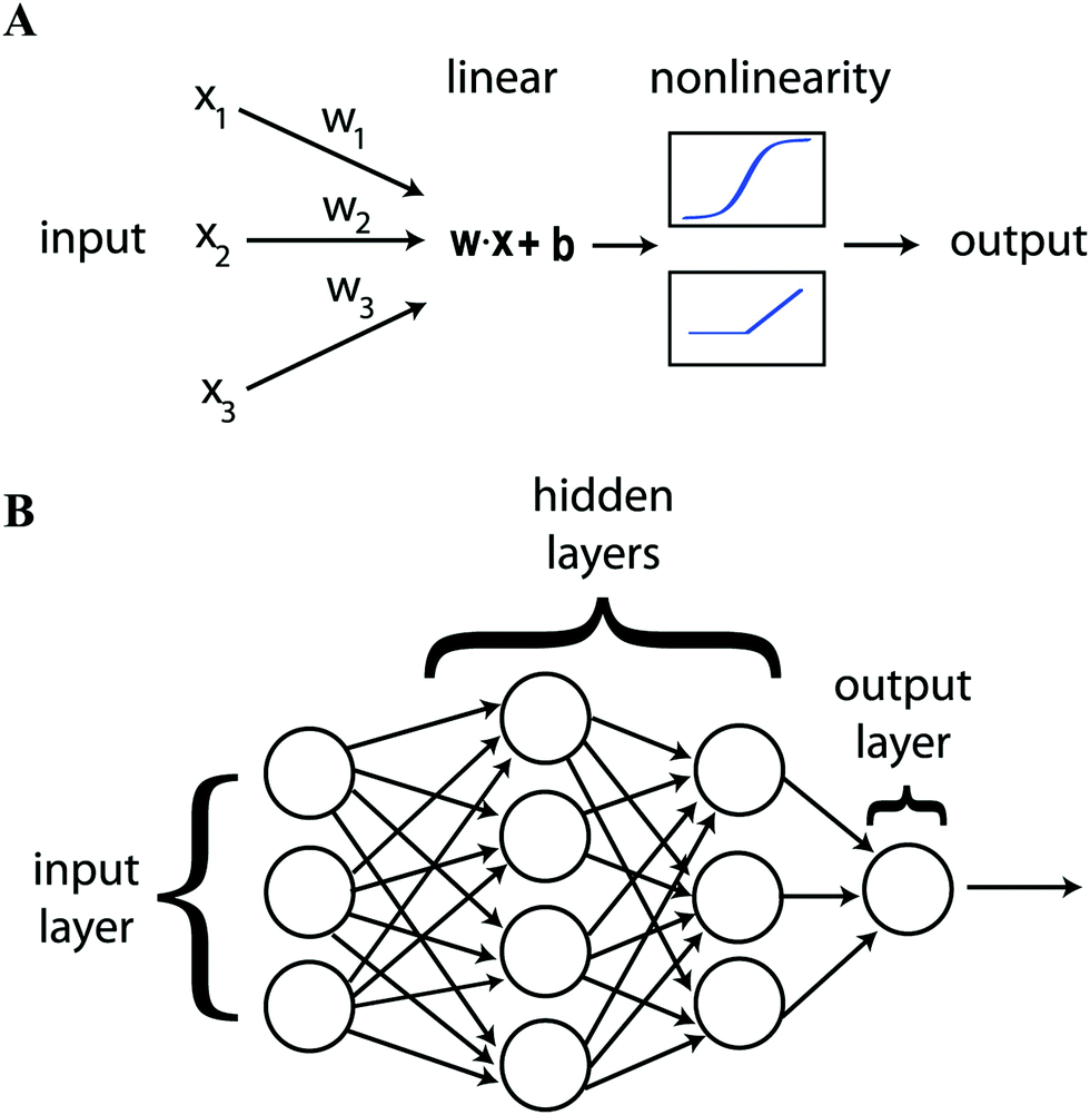 | ||
| Fig. 1 Showing (A) the parts that go to make up an individual neuron and (B) how neurons are combined in layers to construct an artificial neural network. Reproduced with permission from ref. 5. | ||
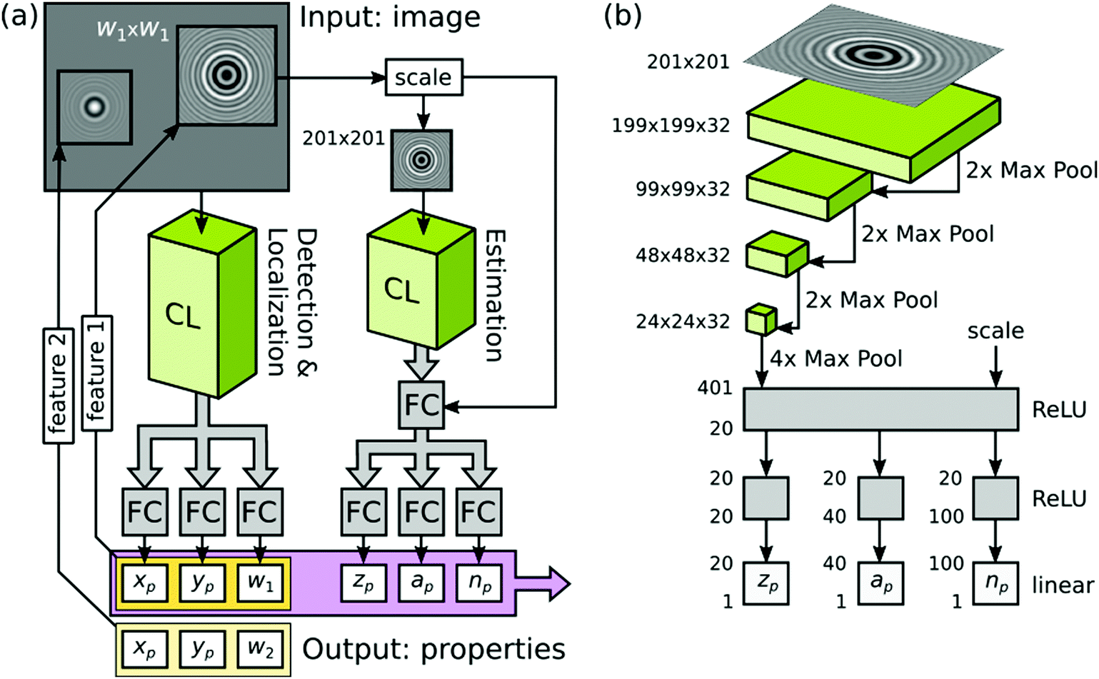 | ||
| Fig. 2 Showing (a) the tracking task broken into two separate steps each handled by convolution layers (CL) with the concentric ring scattering pattern inset and (b) the convolution neural network in detail, convolution layers (green), fully connected layers (FC, gray), course graining (Max Pool) and activation function (here a rectified linear unit, which gives 0 if the input is negative or the input itself if it is positive, ReLU) indicated. In (b) the size of the input image, in terms of pixels, is specified. Below this, the size of the grid of neurons in each convolution layer is given as width × height × depth. Each layer of depth corresponds to a different convolution kernel. At each Max Pool layer the degree of course graining is also indicated numerically. At the end of the convolution stages a Max Pool layer is employed to reduce the final grid of neurons to a 401 unit long vector. The elements of this vector are combined via an ReLU function to reduce the vector to 20 elements that are fully connected via three separate ReLU functions to provide the estimates of depth zp, size ap and refractive index np for the particle. Reprinted with permission from ref. 53 Copyright 2020 American Chemical Society. | ||
Schneider and coworkers use an ANN based image analysis method to rapidly measure the core and shell diameters for a stream of core–shell particles.50 They have in mind an application where microfluidics is used to separate structured particles into separate channels and hence they are pleased to achieve reasonable performance with synthetic images of isolated, centred particles with relatively constrained characteristics. Both the SVR approach, described above,49 and the ANN approach analyse the scattering from a particle via the use of a large quantity of calculated scattering patterns. The ANN is trained using the calculated patterns and then provides predictions of the size parameters that vary smoothly over the range spanned by the training data.50 The SVR makes predictions based on a direct comparison to the training data. The discrete sampling of the parameter space, implied by SVR, can lead to predictions being unhelpfully dominated by one support vector or another which can lead to systematic errors.
For many problems, a neural network where every part of the input can be combined with every other part is not ideal.57 For example, in an image processing problem it may be that only local pixels need to be considered together. Convolution neural networks (CNN) were developed to address this situation. The output from one layer of the network is passed on to the input of the next layer via convolution with a kernel of limited size.5 Because the convolution process treats a local set of pixels in the same way based on their relative positions, but regardless of their absolute location on the input grid, the CNN has the property of translational invariance. CNNs do not typically have a convolution step at each layer, instead these are interspersed with coarse graining layers. These layers sub-sample the previous one, for example, feeding forward the maximum value from a group of neighbouring outputs, Fig. 2(b). Such a sub-sampling layer, which achieves coarse graining via replacing a small region of neurons by the maximum value from those neuron, is known as a Max Pool layer.
Newby and coworkers use a CNN for finding and determining the precise position of particles with the frames and movies for training the system again created via simulation. Here a wide range of styles of data are considered.51 This system is exceptional at avoiding false positives (finding a particle where none exists) and false negatives (failing to find a particle that does exist). However, the position determination is outperformed by simpler methods that do not involve machine learning, especially when each time point consists of a single image rather than a z-stack.
Most recently, Altman and Grier broke the problem of characterizing a colloidal dispersion into two parts: firstly, they locate the particles in two dimensions and, secondly, they determine the radius, refractive index and depth of the particle, Fig. 2(a).53 The two halves are very different kinds of problem but they are each solved here using a CNN. The first problem is to provide a “yes” or “no” answer to the question of whether there is a particle at each location; the second problem is to provide real numbered values to three characteristics. The output of the first stage is used to isolate small regions of the image, which contain the concentric ring pattern, that are then passed to the second CNN for analysis (this is markedly different to the SVR approach by some of the same team49,56). Here, training has been carried out using synthetic data based on a single particle, together with added noise, in each training image. The performance of the first stage is a huge improvement over conventional algorithms where the authors suggest that 40% of particles are missed (false negatives). Using the CNN they find that there are fewer than 0.1% of false negatives. The conventional approach misses very large particles whereas the CNN approach misses a few of the very smallest particles. Alongside detecting the particles, the first stage CNN provides coordinates to high accuracy as well as an estimate of the extent of the ring pattern. The second stage CNN provides estimates of radius, refractive index and depth to within 10% for synthetic data. For an experimental test, the authors attempt to discriminate between four different sizes of particle made from two different materials. The results from the commercial system are taken as the ground truth; the machine learning approach reports a somewhat larger number of features. The speed at which features are identified means that the machine learning approach can establish the particle concentration in real time. However, it is found that the CNN struggles significantly to identify the size and the refractive index of the larger polystyrene particles i.e. there is no real cluster in feature space associated with these particles (the smaller polystyrene particles are not great either). The results can be markedly improved by adding a third stage (of non-linear model fitting) to the image data meaning that a robust end-to-end analysis system is achieved by this route.
As an addition to tracking, machine learning has also been applied to the analysis of particle tracks once they have been recorded.60 The intention is to be able to accurately assess track statistics recorded for heterogeneous materials while making as few assumptions as possible. Hierarchical agglomerative clustering, is an unsupervised algorithm that begins with all data points separated and then progressively merges them into larger and larger clusters based on a measure of the distance between clusters. This distance measure can then be used to decide on the optimal number of clusters.1 Here, such clustering based on the track statistics (the standard deviation of the step size distribution) is used to divide particle tracks into similar clusters and then the tracks within each cluster are used to characterise the associated stochastic process. The method has been road tested on agarose gels, mucous and a range of other heterogeneous environments.
Evidently, much progress has been made with particle tracking using machine learning, the problem of feature identification can reasonably be described as solved, at least for dilute dispersions. The problem of determining the precise particle location, size and refractive index, at least at high speed, remains a significant challenge.
3 Ordered particle arrangements
Investigating self-assembly and the onset of order is an essential aspect of understanding matter on the colloidal scale. Here, computer simulations often play a crucial role, leading to very significant challenges in scoping very large data sets or in coarse graining complex colloidal system.3.1 Classifying order
Inspired by the pioneering work of Behler and Parrinello,61 symmetry functions and neural networks have been used by Geiger and Dellago in the detection of ordered structures in molecular dynamics simulations.58 The problem is to rapidly identify known ordered crystal structures and related defect configurations based on the local arrangement of atoms. The main computational cost is characterising this local arrangement via the calculation of symmetry functions, Fig. 3(a). Training is carried out based on the simulation of known ordered phases. Provided that the training data includes the relevant phases then the neural network is fast and efficient; it even succeeds for the more challenging phases of ice.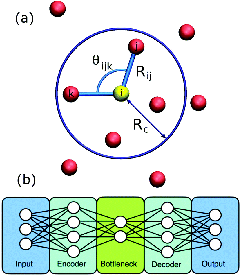 | ||
| Fig. 3 Showing (a) the ingredients for calculating a symmetry function. Sites within a cutoff Rc form part of the symmetry function for the yellow site and are calculated using the relative positions, Rij, and relative angles, θijk. (b) The layout of an autoencoder based on two neural networks. The encoder produces the low dimensional representation and the decoder reconstructs the input from this representation. Reprinted from ref. 58 and 59, with the permission of AIP Publishing. | ||
Dietz and coworkers developed a complete analysis that relies only on nearest neighbours, identified via the Delaunay neighbourhood.62 To give scale invariance, the distances are normalised by the average neighbour distance. In order to be able to distinguish between the crystal structures of interest the site signature is composed of the nearest neighbour distance, the bond angles, the Minkowski structure metric, the Minkowski tensor and the number of neighbours. A modified scalar product of bond orientation order parameters is used to establish whether a site is ordered or disordered. A multi-layer perceptron (ANN using a step function) is trained and then tested on different crystal structures with added noise. The tool is finally used to demonstrate a new level of understanding of the crystallization in a gravitational field where transitions between crystal structures as a function of temperature become evident.
Going to the opposite extreme, Ziletti and coworkers work with an average over a significant region of crystal rather than looking at the neighbour hood of a single site.63 The averaging makes their procedure spectacularly robust, even for highly defective crystals. The machine learning is carried out using the CNNs that were originally developed for classifying images. In order to turn the crystal structure into an image they calculate a composite diffraction pattern made up of the superposition of nine diffraction patterns using three colours. One colour is chosen for each orthogonal axis; for each axis the pattern is calculated for the initial orientation and one rotated ±45° about that axis. The same is repeated for the other two axes using different colours each time. A library of these images for perfect crystal structures make the training and the test data. The trained classifier then performs well for highly imperfect crystals. The authors make the division between an imperfect crystal and an amorphous structure based on the Lindemann criterion. Each classification comes with a probability that the pattern belongs to that structure. For imperfect crystals, this probability reflects the degree of disorder. The downside to this research is the inability to distinguish between crystal structures whose symmetries mean they are identical in the composite diffraction pattern.
3.2 Unsupervised discovery of ordered motifs
Philips and Voth use two approaches to characterise local order in monatomic solids.64 The first approach is to analyse how many neighbours are within the first and subsequent shells i.e. the size of the neighbourhood. The second approach is to use a Fourier description of the arrangement of the neighbouring sites. The size data or the arrangement data are then used to find clusters of similar sites via unsupervised learning using a density based clustering algorithm called DBSCAN.65 For the size data, this can be carried out for every site; for the arrangement data, a subset of sites is used for the learning step and then an archetypal site is found from the centre of each resulting large cluster. The resulting library of archetypes is then compared to the full set of sites in order to create a complete classification. The global description of a sample is given by the complete histogram of sizes or arrangements found; the strength of this approach is the extent to which it is data driven.When unsupervised cluster formation is being used, it is because we assume that there is some parameter, which we do not have access to, that takes a value characteristic of each cluster. A popular route to clustering is the Gaussian mixture model, where it is assumed that this unknown parameter takes on a Gaussian distribution of values within each cluster.5 Spellings and Glotzer have used a description of the atomic environment based on bond orientation to drive first unsupervised (via a Gaussian mixture model) and then supervised (via artificial neural networks) automated analysis of simulation results.66 The training data for the supervised case could have been established using the unsupervised approach first. In both unsupervised and supervised cases, the phase diagram of the simulation results is similar to that determined by manual analysis; the ANN approach succeeded with complex crystal structures for polyatomic systems where manual analysis had previously been avoided.
In a new departure, Boattini and coworkers used a neural-network based autoencoder to create a compact representation of the bond order around each site.59 An autoencoder begins life as two neural networks, the first (the encoder) performs a dimensional reduction and the second neural network (the decoder) takes this compact representation and expands it again, Fig. 3(b). The pair are trained by evaluating whether the input data is reproduced at the output of the decoder.14 Once the training is complete, the decoder is discarded and the encoder is used alone to create a compact description which here was then formed into clusters without supervision via a Gaussian mixture model. The key bond order components, that most influenced the compact description created by the autoencoder, could also be identified. This made it possible to understand which symmetries were driving the clustering. The authors applied this approach to a very wide variety of example systems; it was able to cluster the sites into groupings equally well to the historic, manually tuned approaches.
3.3 Finding pathways between ordered motifs
Unsupervised machine learning can be used to suggest the pathway via which an arrangement of particles was formed so as to illuminate the process of self-assembly. One example system, explored by Long and Ferguson, is anisotropic patchy particles studied via Brownian dynamics simulations.69 Here the pathway refers to a connected trajectory through a space in which patchy particle aggregates of different size and shape appear as distinct points. To be useful, similar aggregates should be close together in this space; progress along the pathway could then indicate how aggregates might grow or redisperse. To achieve this, each aggregate of particles is represented as a graph and similarity is identified by using the graph-matching IsoRank algorithm.70 If two aggregates are similar it implies that there is a small absolute difference between corresponding particle locations. A characteristic distance between two aggregates captures the differences in location (due to fluctuations or bonding arrangement). Similarity between aggregates, which require a great deal of information to describe, is now being measured as though it were a distance in space. This measure is then used as the basis for a diffusion map, as described below. The resulting pathways, for this specific system, are often composed of two paths that join more-or-less at a right angle. One path is made up of the points representing small compact aggregates and a longer path includes the larger more extended aggregates. As outlined next, the diffusion map is able to execute a dimensionality reduction that captures this non-linear path.Diffusion mapping was first presented in ref. 71 and is an attractive approach to dimensionality reduction in complex data sets.67 For comparison, a traditional method for solving this problem is principal components analysis (PCA) where the data is reduced to the d eigenvectors with the largest eigenvalues from the covariance matrix.1 By this route, an n dimensional data set is reduced to the d < n dimensions that capture the largest variability in the data. This technique is not appropriate when the largest variability of the data occurs along well-connected but non-linear paths. By contrast, a diffusion map can be constructed by first defining a Gaussian kernel which plays the role of a step size distribution for a random walk.67 Sites connected by steps of these sizes form a neighbourhood. Then a diffusion matrix can be calculated for any two sites giving the probability of a single step leading from one site to the other. Powers of the diffusion matrix then give the probabilities of taking increasing numbers of steps to move between the two sites, Fig. 4(a). The diffusion map captures the probability of diffusion between two sites for a particular number of time steps. The diffusion distance is small if there are many high probability paths between the two sites. The dimensionality reduction is achieved by keeping only the dominant d eigenvectors of the diffusion map. Now non-linear paths can be identified as the directions that capture the largest variability in the data, Fig. 4(b).
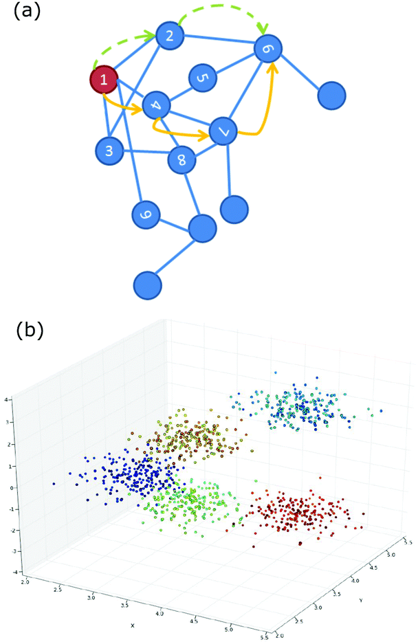 | ||
| Fig. 4 (a) Schematic of the relationship between numbered sites which is captured by a diffusion map. The blue lines are one step; the yellow and green routes are alternative paths between “1” and “6”. (b) Showing the geometrical structure revealed by a diffusion map. Reproduced with permission from ref. 67. | ||
Experimental data can also be used as the basis for a diffusion map and has been explored for the case of aggregating of Janus particles in an oscillating electric field and confined to two dimensions.68 Many tens of thousands of Janus particle aggregates were characterised as graphs and compared. The approach mirrors that described above for patchy particles with the differences between the aggregates quantified by a distance metric which is then used as the basis of the diffusion map. Ultimately, the formation pathway undergoes significant shape changes in response to variations in electric field strength, frequency or salt concentration. The results on chain formation are particularly impressive. The diffusion maps suggests trajectories by which electric field strength and frequency can be used to control whether chains form of relatively uniform length or whether there is a mixture of long chains, rings and branched structures, Fig. 5.
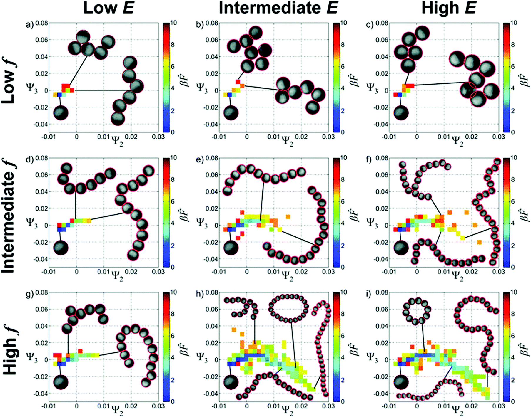 | ||
| Fig. 5 Landscapes for the self-assembly of Janus particles in an AC electric field. Ψ2 and Ψ3 are the eigenvalues that are being used to describe the self-assembly as controlled using the amplitude, E, and the frequency, f, of the field. Reproduced from ref. 68 with permission from The Royal Society of Chemistry. | ||
The strength of the diffusion mapping approach is that it is based on kinetic proximity between different system configurations i.e. the map represents the probability of diffusion between configurations. That the system dynamics are well-modeled as a diffusion process is an assumption.72 One application area where this approach is crucial is in the creation of colloidal memory elements.73 Here transitions between states describe how easy it is to write to a memory element and subsequently how long lived the state is. The exploration here is based on Brownian dynamics simulations of four or six halo particles around a central particle. The outcome is a design criteria for the relative size of central and halo particles in each case.
Whereas the preceding examples relate to studies of small aggregates, Reinhart and coworkers propose a method of unsupervised crystal structure identification based on topology by making use of diffusion mapping.74 Common Neighbour Analysis (CNA) is used to construct a characteristic signature from the connectivity of a particle's neighbours.75 This is followed by a graph matching step (with an MLP-based speed-up) and then by the construction of a diffusion map to reduce the dimensionality. Using cluster size on the diffusion map as an indicator of importance, the key structural motifs are identified as corresponding to different crystal structures, surface structures or other defects. A Voronoi construction is then used to partition the diffusion map so that all sites can be classified. This approach is particularly effective close to surfaces and defects; although, this needs to be weighed against the computational cost. It has been extended to binary crystals in two dimensions by including specie identity in the graph and speeded up via the use of relative graphlet frequencies.76 By this route Reinhart and Panagiotopoulos are able to demonstrate that some crystal structures, previously found in simulations, are actually part of a continuous transition that runs across multiple structures.
Dimensional reduction using both linear and non-linear techniques was combined with unsupervised learning by Adorf and coworkers.77 They went on to provide an alternative route to discovering the pathways to self-assembly, for example crystallization via nucleation. They began with a large number of descriptors including bond angles, bond lengths, spherical harmonic order parameters and the bispectrum environment descriptor. Via PCA they reduce this down to its 20 most important components. These are further reduced using the uniform manifold approximation and projection for dimensional reduction (UMAP) algorithm, an alternative nonlinear route to dimensionality reduction.78 The resulting space was then used for finding clusters. Solid and liquid regions were easily separated and they were able to identify particular crystal structures as well as some less perfectly ordered solid structures. The development of clusters in the reduced dimension space gave an indication of the self-assembly route.
As outlined above, the study of self-assembly and the onset of order on the colloidal scale is now served by a wide array of machine learning tools. Reducing the problems to a size that is computationally manageable remains a significant challenge.
4 Glasses
The dynamics of glasses are characterized by occasional rearrangements which are sometimes known as cage breaking events.81,82 However, previous attempts to relate the likelihood of a relaxation event to the local structure have been unsuccessful. Typically, the local structure has been characterized via free volume or bond orientational order which fail to have predictive power. By contrast, the scattering of sound waves can be used to successfully demonstrate the existence of defects in the local structure of glasses.83 Unfortunately, this does not help identify the associated local structure. As we consider machine learning, it is interesting to note that glassy dynamics are also exhibited by under-parameterised deep neural networks, i.e. where the number of neurons in a hidden layer have been drastically reduced.84 The process of training the network is equivalent to quenching a liquid to low temperature; the loss function, which is to be minimised during training, is analogous to the system energy. Such glassy dynamics are not observed when training a deep neural network with a more traditional architecture.4.1 Supervised learning using dynamics
Machine learning has been used to quantify very subtle correlations between the local structure around a site and the susceptibility towards a rearrangement event at that site, and to develop a new conceptual approach.79,83,85 This research, led by Liu, began with data from experiments in two dimensions and computer simulations in two and three dimensions. The data is in the form of the structure of sites that are known to be about to rearrange (labeled 1, ‘soft’) and the structure of sites where no rearrangement occurs (labeled 0, ‘hard’). Instead of characterizing the sites using free volume or the degree of bond orientational order, a multitude of structure functions (Fig. 3(a)) are calculated (typically 160 for each site).61 These fall into two classes: radial structure functions based on the number of neighbours that fall within a certain distance and angular structure functions based on the bond angles with near neighbours. This super-abundance of descriptors for each site are then analysed using an SVM which finds the hyperplane that best separates the ‘soft’ from the ‘hard’ sites. The ‘softness’ of a site can then be characterized as the sites shortest distance to the hyperplane. Having determined the location of the dividing hyperplane using carefully selected data, the ‘softness’ can then be evaluated for all of the sites in an experimental or computational system. The authors demonstrate that this approach identifies 20–25% of the sites in each system as ‘soft’ and these sites are the location of the majority of rearrangements.83 Hence this measure of local structure is strongly correlated with the relaxation dynamics of these glasses, Fig. 6.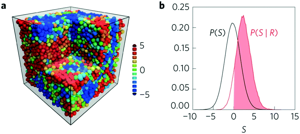 | ||
| Fig. 6 Showing (a) a simulation snapshot of the system with particles coloured according to their softness from red (soft) to blue (hard). (b) The distribution of softness for the particles that are about to rearrange (red) compared to all of the particles (black). The solid red indicates that 90% of the particles that are about to rearrange have a positive softness value. Reprinted by permission from Springer Nature: ref. 79. | ||
This team have shown that there is indeed structure buried within a disordered glass and that it can be quantified via the parameter ‘softness’. Indeed, the slow, non-exponential dynamics of glasses can be related back to the evolution of the ‘softness’ in time.79 It is satisfying to be able to relate the dynamics to the structure, this characterization of the local structure, as currently specified, does rely on substantial detail.86 Using the local coordination number or the local energy are far less successful as predictors. By contrast, it is possible to identify the subset of structure functions that most control the ‘softness’ and to ignore the rest without sacrificing very much predictive power.85 In general, soft sites have fewer near neighbours with larger angles between them.83 It may be necessary to accept, that it is quite involved to describe a broken cage.
A vast quantity of experimental and computational results have been deployed to show that the same framework can be used to describe the behaviour of disordered solids over a very broad range of systems from atomic, through colloidal to granular.87 The spatial correlation length in the particle positions and spatial correlation length in softness are found to be essentially equal over seven orders of magnitude in particle diameter. These lengths are approximately one particle diameter.88 It is also demonstrated that there is a universal yield strain for such systems suggesting that the macroscopic shape change that is required is universal. The change in the mean softness in response to the applied yield strain may be independent of the particle diameter.
In spite of the disquiet over the detailed particle-level information required, the concept of “softness”, established via machine learning, profoundly informs the understanding of glasses and can clearly be very widely applied. Experiments on the hopping behaviour of bidisperse colloidal particles have been used to demonstrate that, while the distribution of hopping times has a stretched exponential form, the hopping time at a single “softness” has an exponential form.88I.e. colloids with similar local environments are characterised by a particular softness value and exhibit exponential relaxation with the same activation time. This had previously been suggested using computer simulations.79 Further simulations of polycrystalline solids have shown that the idea of an energy barrier related to a “softness” can be extended to atoms at grain boundaries.89
Subsequent studies have applied the learning of “softness” to simulations of thin polymer films and pillars and to the analysis of granular experiments using spheres, dimers and ellipsoids.90–92 In the former case, Sussman and coworkers found that the enhanced dynamics close to the surface of a polymer thin film is uncorrelated with the “softness” parameter. The SVM approach worked as before for predicting which sites would be likely to move, it just failed to identify any changes close to the free surface (or to the substrate). The authors tried a broader variety of techniques in order to search for structural differences close to the surface but found none. Instead they found an Arrhenius process close to the surface that is wholly unrelated to any structural differences.90 For the case of polymer pillars, the relationship between “softness” and mesoscale shear banding was investigated. Additionally, a parallel classification of planes into “weak” and “strong” was created by a similar route. The analysis of the simulation results demonstrated the key role of surface defects in leading to pillar failure.91 The experiments using spheres, dimers and ellipses demonstrated that a naive implementation of the “softness” concept worked reasonably for spheres and ellipses but quite poorly for dimers. Harrington and coworkers modified the family of structure functions in order to better match the arrangements of anisotropic particles. This gave an excellent ability to predict rearrangements for ellipses and reasonable performance for dimers.92
Inspired by the success of SVMs, the “softness” approach has been generalized via the use of graph neural networks that are able to predict the location of structural rearrangements.80 Graph neural networks are being envisioned as a flexible machine learning methodology in which the role of the algorithm in shaping the character of the solution can be productively employed.57 The idea is to avoid the distinction between a “hand-engineered” data pre-processing step (such as choosing a set of structure functions83) and an “end-to-end” approach (where any assumptions about the data, including those embodied in a pre-processing step are minimised). With a graph neural network, computations are performed on entities and the relationships between them. This makes it possible for the algorithm to learn about the way entities relate to one another rather than this being designed by hand. However, the algorithm does not have the freedom to decide what the entities are or which ones interact directly. In our context, within the graph formalism, the entities (i.e. nodes) are the particles and the relationships (i.e. edges) are the directed vectors between two particles within a pre-defined distance of one another; the algorithm then learns how to characterise the environment of each particle without the explicit use of a family of structure functions. Unlike a neural network based on fully connected layers, the graph neural network could not learn that one particle relaxes in instantaneous response to the location of a particle that is a great distance away in the sample.
Bapst and coworkers obtain training and test data by carrying out simulations of a Kob–Anderson mixture in three dimensions from which they calculate the propensity of each particle.80 The propensity is the mean square particle displacement averaged over particles sites with the same initial configuration that the graph neural network is trained to predict.95 All N particles from the simulation are included in the graph; particles within 2 simulation units of each other are connected by edges, information about particle type is the feature recorded at the nodes. The feature recorded at each edge is the three-dimensional relative position of the two neighbours. The first step is to encode these features via separate multi-layer perceptrons (MLPs) resulting in a low-dimensional representation. All edges are then updated based on the characteristics of the neighbouring nodes passed through an MLP. Subsequently, the nodes are updated based on their connected edges in a similar manner. This is repeated through seven cycles (corresponding to particles influences being propagated to greater distances) and then there is a decoding step leading to the calculation of the propensity for each particle, Fig. 7. In the training process, these propensities are compared to the expected values; the properties of the MLPs are modified until the propensities match. Initially, they test their ability to predict the propensity at long times based on the initial particle locations and find that the GNN based approach out performs the competitors including the SVM approach described above. They further explore predictive ability as a function of both temperature and shear. Again the GNN approach performs best; none-the-less they are not able to predict when a sample will yield under shear. To address the complaint that machine learning does not aid understanding, considerable effort has been expended on analysing the properties of the network. For example, they vary the attributes used to describe each particle to establish which are important. Furthermore, they take a pre-trained network and require it to make predictions based on constrained input data. They find that the short time dynamics only depend on the first two shells of particles. However, the quality of predictions about the long time dynamics degrades when you lose particles even in the fourth shell. By conducting this style of analysis as a function of temperature, they argue that the system exhibits an increasing correlation length as it becomes a glass.80
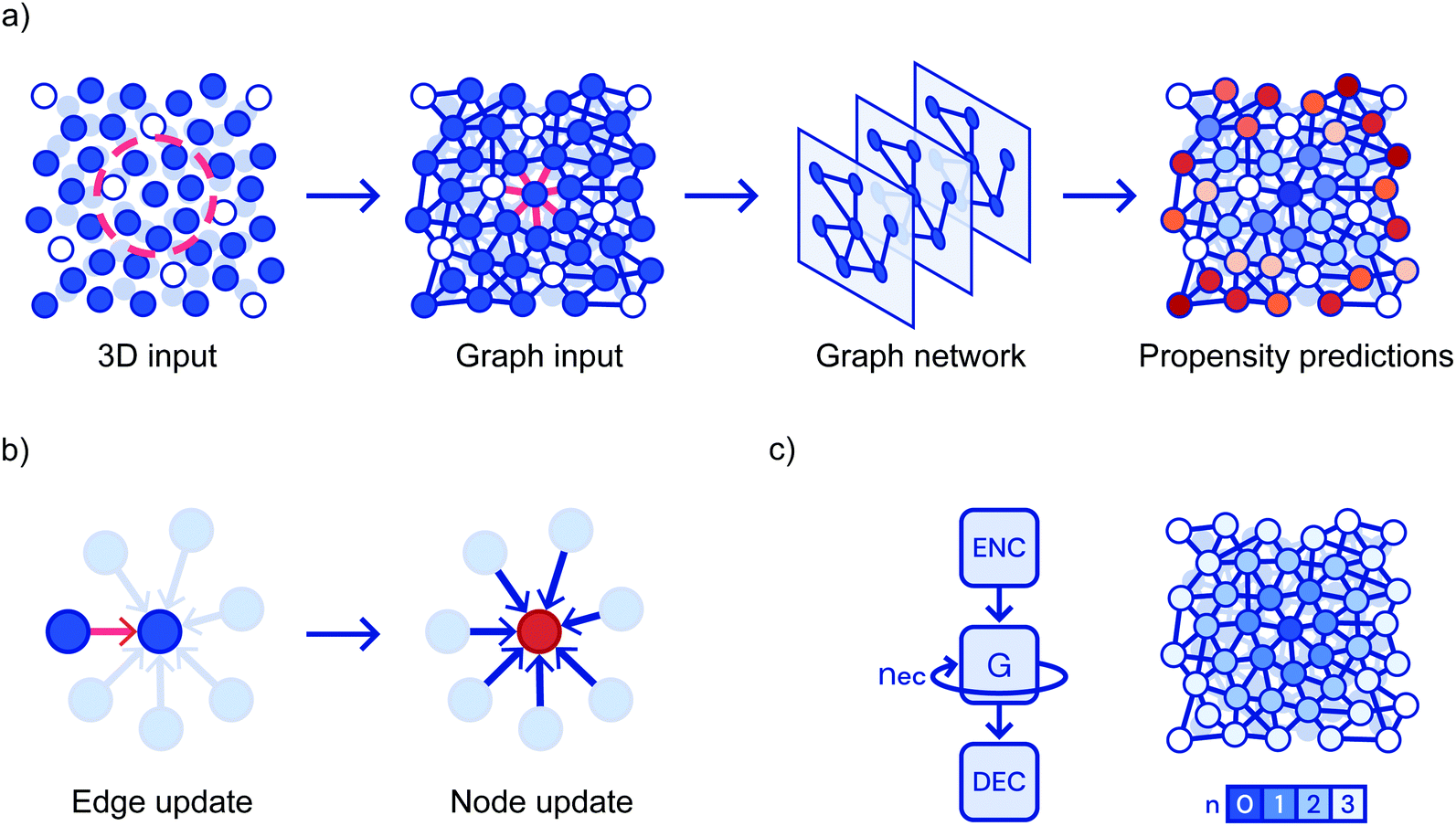 | ||
| Fig. 7 Showing (a) a flowchart of the prediction pipeline used when graph neural networks are applied to glasses; (b) the update steps and, (c) the repeated cycles corresponding to progressively more distant particles. Reprinted by permission from Springer Nature: ref. 80. | ||
Simultaneously, Swanson and coworkers compared the performance of convolution neural networks and a related type of graph neural network analysing particle positions in two dimensional simulations.93 Both approaches were used to categorise simulation snapshots as either ‘liquid’ or ‘glass’. The CNN took input data in the form of an image while the GNN took particles as nodes and relative positions as directed edges. The two techniques were able to classify snapshots essentially without error. In the case of the GNN, it was possible to gain understanding by evaluating a quantity called the ‘self-attention’.96 Here the aspects of the data that the algorithm pays most attention to are evaluated. Based on this information, it was established that the classification was being made on the basis of the location of B-type particles (the smaller ones) and their relationship to their neighbours. The B-type particles form ‘dimers’ with ‘high attention’ edges in the liquid, but not in the glass, Fig. 8. Furthermore, there is a wealth of information from the variation of the ‘self-attention’ with temperature.
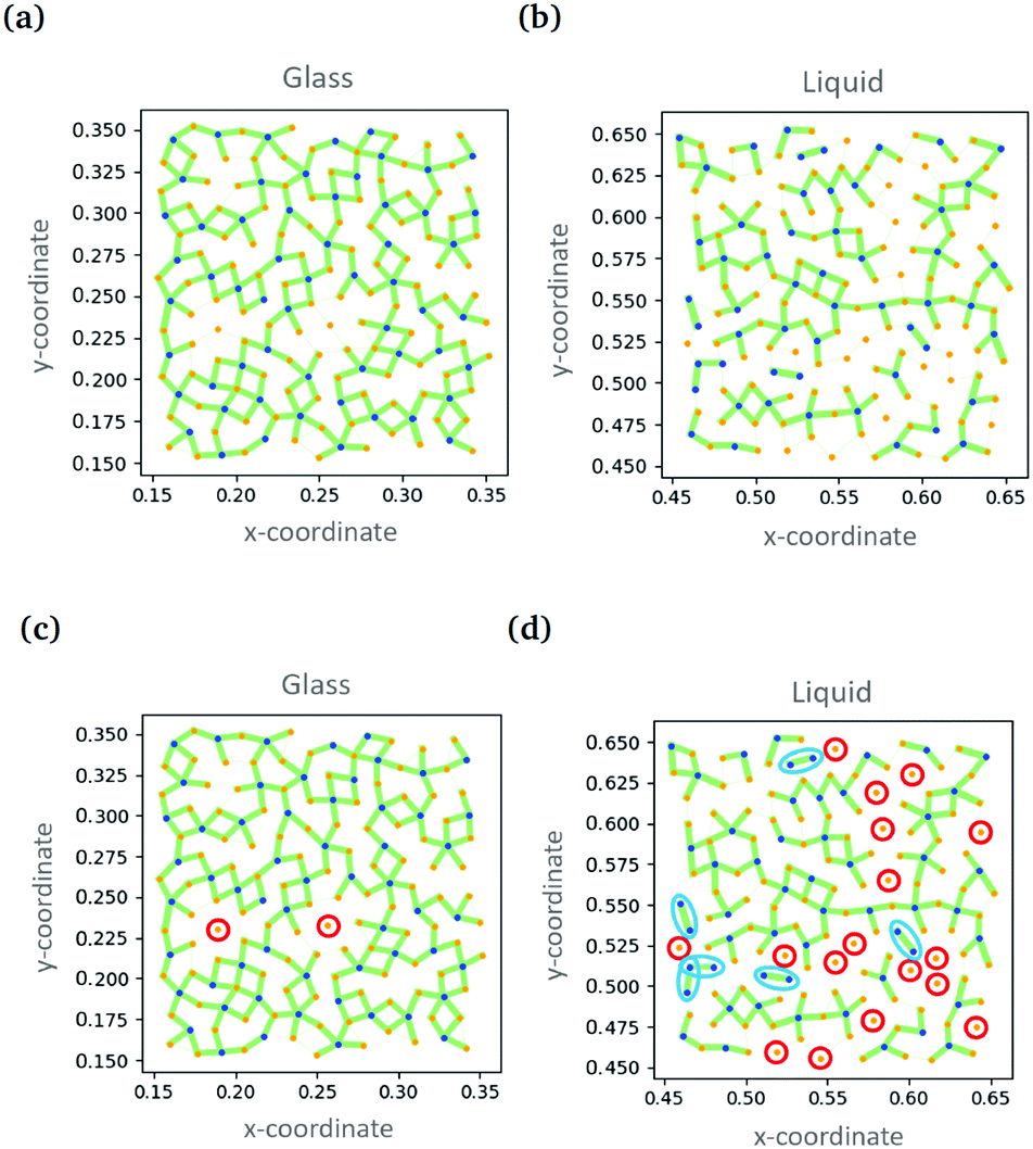 | ||
| Fig. 8 Showing the ‘self-attention’ in the glass and liquid states. Connections between particles are shown as green lines with the line thickness indicating the weight of attention. (c) and (d) show the same data as (a) and (b) with isolated A-type particles and dimers of B-type particles highlighted. Reproduced from ref. 93 with permission from The Royal Society of Chemistry. | ||
4.2 Unsupervised learning based on statics alone
More recently, glasses have been addressed using an approach, first described in Section 3.2, which avoids using information about the particle dynamics.97 Here snapshots of the arrangement of particles are taken from computer simulations of glasses. Bond order parameters are combined with an autoencoder to provide a compact description of the particle sites.59 The compact description is then the basis of an unsupervised division of the sites into two classes. For both binary hard spheres and Wahnstrom glasses, the probability of being in one of the two classes of site is very highly correlated with the propensity; for the Kob–Anderson glass the correlation is not quite as strong. The probability of being a member of the faster cluster is evidently revealing that there is an essential aspect to the local organization.Paret and coworkers have also developed an unsupervised clustering procedure based on maximising the information provided by the clusters (structural communities) without appealing to dynamic information to control the process.98 They have explored this approach for several different glass simulations, separately using the radial distribution and the angular distribution to establish which particles belong in each cluster. How the particles are clustered typically depends on which of these approaches are chosen. Again, they compare all the variant clusters to the dynamics. The two are well-correlated for the Wahnstrom mixture and somewhat less well for the Kob–Anderson and harmonic spheres simulations indicating that the Wahnstrom/Kob–Anderson division is robust over two very different implementations.
In glass research, machine learning has added the important concept of softness and a new way of working. Both supervised and unsupervised learning are providing additional understanding and will permit a whole slew of questions to be addressed in the future.
5 Composite materials
Using machine learning in the design of complex materials at the atomic level has been explored extensively in recent years.100–102 This includes research to optimise specific properties of crystalline materials via iterating between experiments in the lab and the generation of refined computational suggestions.103 In this context, a cost function is being minimised for which each new “function evaluation” involves fabricating a new sample. Optimisation problems involving a cost function that is punishing to evaluate have been the focus of machine learning techniques for a long time. A common approach is to model what is already known about the parameter space using a Gaussian process104 and then to further explore the parameter space via a trade off between regions where the cost function is likely to be low and regions where the uncertainty in the predictions of the cost function is very high; the quantity which captures this trade-off is usually known as the ‘expected improvement’. This approach has variously been called kriging, adaptive design and efficient global optimization.105 At the moment this approach is not being used to design soft materials, although it has been deployed to design polymer molecules,106 image pre-processing protocols107 and to optimally position boundaries on phase diagrams.108 Alternative techniques have been used by researchers to design composite materials at the mesoscale and it is this that I focus on below.A group led by Buehler have targeted the response of a two-dimensional “checker-board” material to crack propagation as a model system for computational design.94,109,110 The aim is to harness the machine learning technology that proved so successful in winning the game AlphaGo to the service of composite materials.111 In both game playing and materials design, the number of possible arrangements or moves is far too large to search exhaustively. Hence better strategies are required which learn to go beyond what is available from a modest set of training data. The target here is a sheet of material made up of square patches with different properties drawn from a palette of two or three options. The test applied, to judge the material performance, is the propagation of a crack from one side when the material is under tension.
In the first example,109 Gu and coworkers consider squares of material which are either soft or stiff. For 8 × 8 and 16 × 16 grids they want to discover the optimal arrangement of the soft and stiff squares. For the training data, a finite element model is used to calculate strength and toughness of a particular arrangement, however, they do not attempt to learn real valued quantities here. Instead they create an ordered list of designs and give the top half the label “good”, based on toughness or strength, with the bottom half designated “bad”. It is these categorical labels that are then the focus of the learning process; new arrangements are given a probability of being “good” and hence it is possible to rank the designs based on these probabilities. These ranks can then be compared to the outcome of the finite element model to evaluate the performance of the machine learning. As machine learning approaches, they compare a neural network based on single layer perceptrons with softmax classifier with a CNN. They show that strength and toughness can be accurately predicted using this approach even with a very small amount of training data, from this they conclude that they could apply this approach to much larger systems. The common motif of having soft squares to reduce the stress concentration around the crack tip is straightforward to understand. The compression response of cellular solids on a similar grid has also now been tackled, where the full response curve was learnt rather than a ranking.112
In an effort to push the performance of their model materials well beyond that of the training data, the Buehler team has targeted a similar two-dimensional material (combined with finite element modeling of toughness) but here with three different building blocks – either isotropic, stiff along x or stiff along y.110 To move the machine learning model beyond the training data they introduce a self-learning aspect. In every sampling loop, 10% of the designs are based on the top performing designs from the previous loop. Hence the three different blocks are preferentially placed where they appear to be most effective; noise is added to prevent the self-learning converging to a local minimum. By this route the composite designs rapidly diverge away from the training data in terms of both design and performance, indeed the final output is completely separated in composition space from the data that was used in the initial training. The composite designs are also tested experimentally using additive manufacturing.110
Yu and coworkers have returned to the soft and stiff squares, but have now harnessed a genetic algorithm to enhance the self-learning part of the composite design.94 They begin by training a CNN on composite designs combined with toughness values calculated using the finite element model. Once trained the output of the CNN becomes the parent compositions for the genetic algorithm. Self-evolution begins by seeding the CNN with an initial population of random composite designs. The CNN scores each one according to its material properties and passes them on to the genetic algorithm, Fig. 9. The genetic algorithm combines and mutates the composite designs so as to optimise performance;113 the choice of parents is based on both fitness and diversity. The children, i.e. new designs, are then re-input to the CNN. After 100 iterations around this loop the toughness has improved markedly. Part of the design is simply the stress concentration reduction strategy of soft material near the crack tip. Intriguingly, many of the high performance composite designs involve soft material at the edges of the grid which appear to have a significant influence on the shear stress distribution.
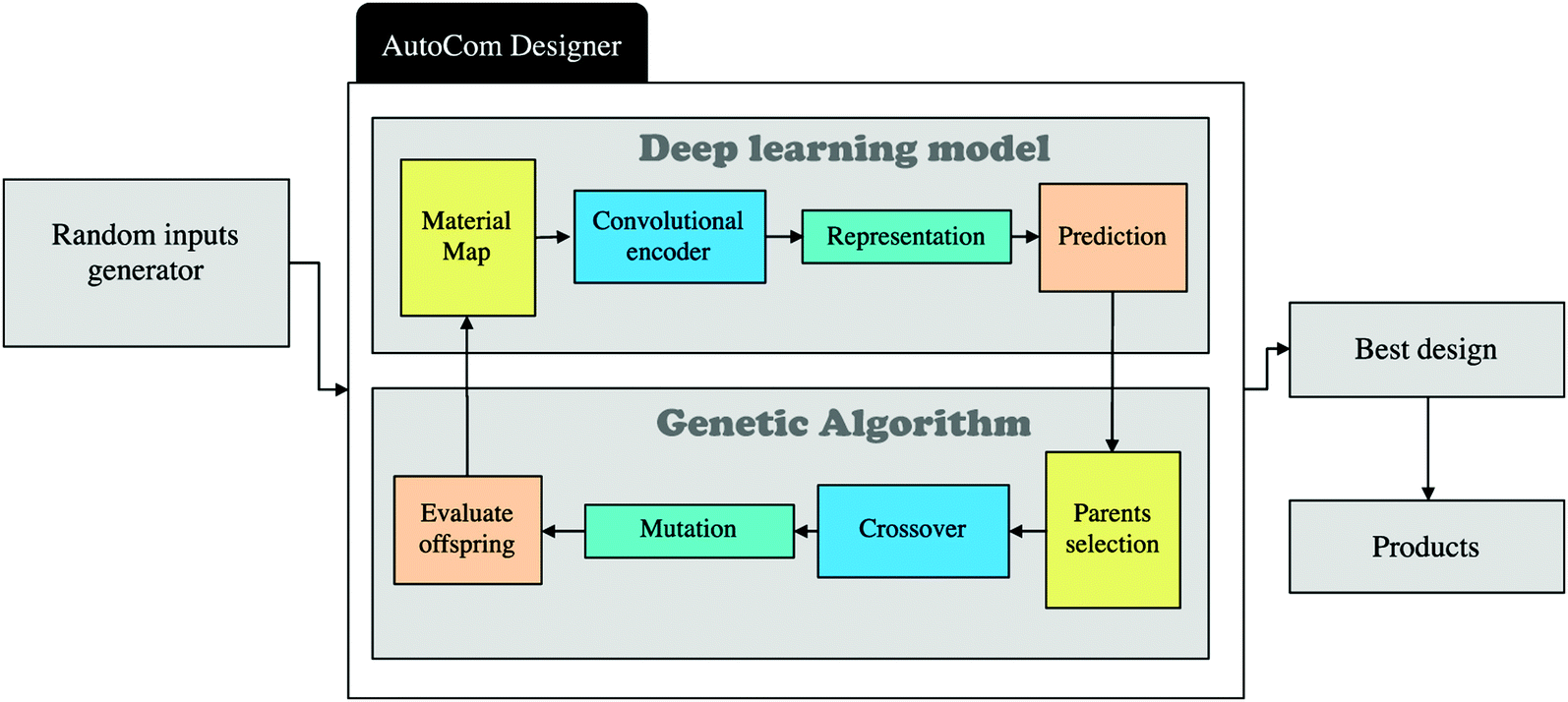 | ||
| Fig. 9 Showing a flow chart of a self-learning procedure for composite materials design. From ref. 94 copyright IOP Publishing. Reproduced with permission. | ||
Finally, Kumar and coworkers have taken on the challenge of complex composite design in three dimensions with the aim of creating the desired anisotropic elastic properties.99 This team is keen to create metamaterials while avoiding creating stress concentrations due to the use of trusses and or plates. To do this they focus on materials that are derived from the spinodal domain pattern familiar from phase separation. They have developed a machine learning route to determine what spinodal-like arrangement would give the required mechanical properties. They begin with the Gaussian Random Field representation of the spinodal pattern114 and introduce anisotropy by parameterising the direction of the spatial wavevectors in terms of angles θ1, θ2, θ3. These angular limits, combined with the volume fraction of solid material, ρ, specify the structure which can range from lamellar, through conventional isotropic spinodal to columnar, Fig. 10. Elastic properties are calculated via the finite element method and then represented as a three dimensional elastic surface. They use a deep neural network to model the relationship between the four material parameters and the nine independent elastic moduli. At this point, Kumar and coworkers can predict elastic properties based on their design parameters; they aim to solve the inverse problem of finding the design parameters that give the desired elastic properties. A challenge is that multiple composite designs may be able to give the required properties. Typically, the neural network tends to favour sets of θi values that are all intermediate, even when one angle was extreme in the comparison data; the volume fraction tends to match the data very accurately. Overall, this is a bold step towards computer guided materials design.
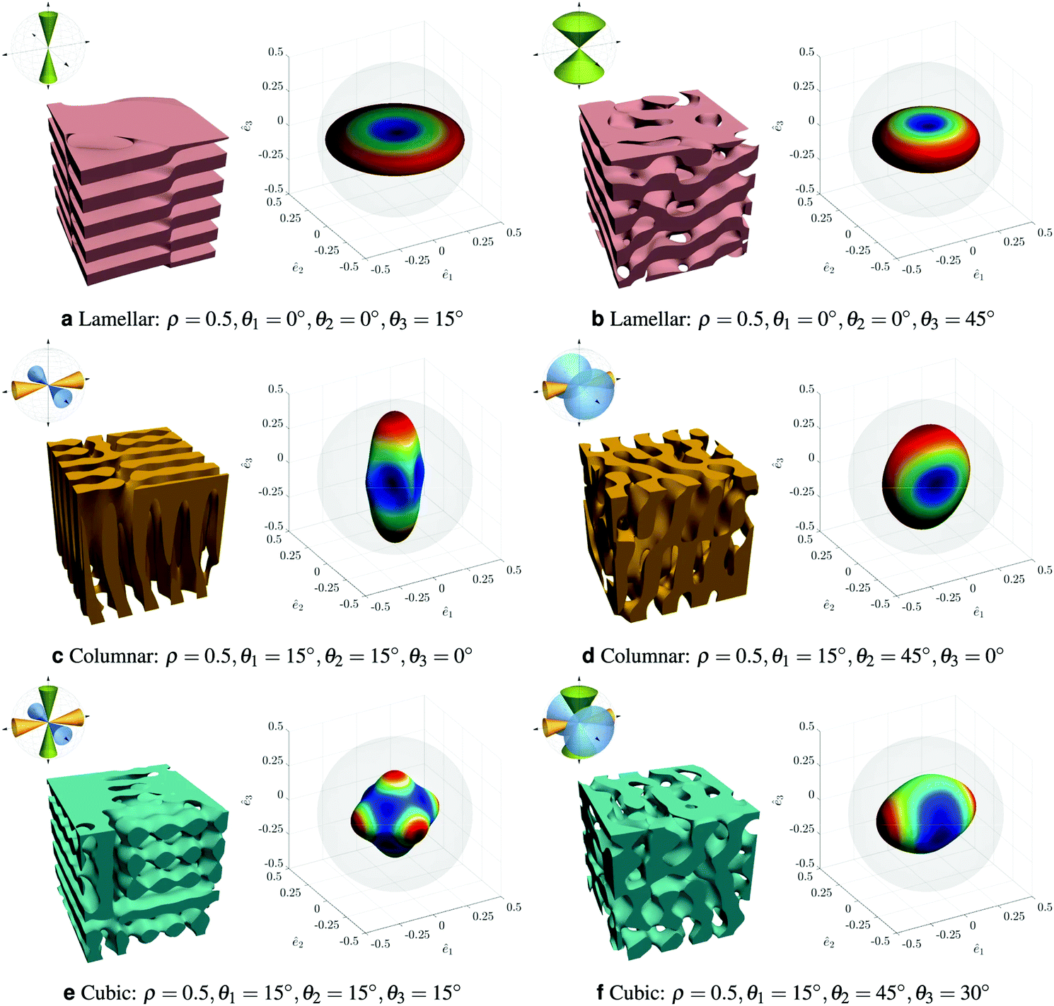 | ||
| Fig. 10 Showing a range of anisotropic spinodal-like structures and their properties presented as elastic surfaces. Reproduced with permission from ref. 99. | ||
Optimizing soft composite design is an area in its infancy; indeed, the examples above are not traditional soft composite materials. Nonetheless, the approach of combining machine learning with a random mutation of design looks to be a fruitful one to pursue.94
6 Conclusions
Machine learning is becoming increasingly widely used by the soft matter community. It is enabling old problems to be solved faster and new problems to be solved for the first time. Within the examples above, it is interesting to note that there is a clear division in the way that machine learning is being used. For some, the ability to make predictions is key and hence the trained algorithm is the tool. For others, it is the ability to interrogate the algorithm to determine how it is making predictions that paves the way to new understanding. The composite materials design community is currently taking on the challenge of developing approaches that are able to go beyond the training data. This will have obvious future application in discovering new classes of complex soft matter and new regimes of behaviour.Conflicts of interest
There are no conflicts to declare.Acknowledgements
I am very grateful to the lockdown journal club, populated by University of Edinburgh graduate students, for drawing my attention to several important papers. The table of contents illustration was kindly provided by E. M. Gould.Notes and references
- G. James, D. Witten, T. Hastie and R. Tibshirani, An Introduction to Statistical Learning, Springer, New York, 2013 Search PubMed.
- I. Goodfellow, Y. Bengio and A. Courville, Deep Learning, MIT Press, 2016 Search PubMed.
- L. Torgo, Data Mining with R, CRC Press, Boca Raton, Florida, 2017 Search PubMed.
- A. L. Ferguson, J. Phys.: Condens. Matter, 2018, 30, 043002 CrossRef PubMed.
- P. Mehta, M. Bukov, C.-H. Wang, A. G. Day, C. Richardson, C. K. Fisher and D. J. Schwab, Phys. Rep., 2019, 810, 1–124 CrossRef PubMed.
- T. Bereau, D. Andrienko and K. Kremer, APL Mater., 2016, 4, 053101 CrossRef.
- N. E. Jackson, M. A. Webb and J. J. de Pablo, Curr. Opin. Chem. Eng., 2019, 23, 106–114 CrossRef.
- T. Bereau, Handbook of Materials Modeling, Springer, Cham, 2019 Search PubMed.
- F. Cichos, K. Gustavsson, B. Mehlig and G. Volpe, Nat. Mach. Intell., 2020, 2, 94–103 CrossRef.
- S. L. Brunton, B. R. Noack and P. Koumoutsakos, Annu. Rev. Fluid Mech., 2020, 52, 477–508 CrossRef.
- V. Venkatasubramanian, AIChE J., 2019, 65, 466–478 CrossRef CAS.
- E. Y. Lee, B. M. Fulan, G. C. L. Wong and A. L. Ferguson, Proc. Natl. Acad. Sci. U. S. A., 2016, 113, 13588–13593 CrossRef CAS PubMed.
- J. K. Gupta, D. J. Adams and N. G. Berry, Chem. Sci., 2016, 7, 4713–4719 RSC.
- M. J. Tro, N. Charest, Z. Taitz, J.-E. Shea and M. T. Bowers, J. Phys. Chem. B, 2019, 123, 5256–5264 CrossRef CAS PubMed.
- J. W. Khor, N. Jean, E. S. Luxenberg, S. Ermon and S. K. Y. Tang, Soft Matter, 2020, 15, 1361–1372 RSC.
- Y. Wu, Y. Rivenson, H. Wang, Y. Luo, E. Ben-David, L. A. Bentolila, C. Pritz and A. Ozcan, Nat. Methods, 2019, 16, 1323–1331 CrossRef CAS PubMed.
- G. Simionato, K. Hinkelmann, R. Chachanidze, P. Bianchi, E. Fermo, R. van Wijk, M. Leonetti, C. Wagner, L. Kaestner and S. Quint, 2020, https://arxiv.org/abs/2005.08040.
- S.-C. Lin and M. Oettel, SciPost Phys., 2019, 6, 025 CrossRef CAS.
- S.-C. Lin, G. Martius and M. Oettel, J. Chem. Phys., 2020, 152, 021102 CrossRef CAS PubMed.
- L. Hamadeh, S. Imran, M. Bencsik, G. R. Sharpe, M. A. Johnson and D. J. Fairhurst, Sci. Rep., 2020, 10, 3313 CrossRef CAS PubMed.
- G. Bell, Philos. Trans. R. Soc., A, 2016, 374, 20150137 CrossRef PubMed.
- M. Walters, Q. Wei and J. Z. Y. Chen, Phys. Rev. E, 2019, 99, 062701 CrossRef CAS PubMed.
- H. Doi, K. Z. Takahashi, K. Tagashira, J. Fukuda and T. Aoyagi, Sci. Rep., 2019, 9, 16370 CrossRef PubMed.
- C.-H. Chen, K. Tanaka and K. Funatsu, Mol. Inf., 2019, 38, 1800095 CrossRef PubMed.
- E. N. Minor, S. D. Howard, A. A. S. Green, M. A. Glaser, C. S. Park and N. A. Clark, Soft Matter, 2020, 16, 1751–1759 RSC.
- H. Y. D. Sigaki, E. K. Lenzi, R. S. Zola, M. Perc and H. V. Ribeiro, Sci. Rep., 2020, 10, 7664 CrossRef CAS PubMed.
- I. E. Lagaris, A. Likas and D. I. Fotiadis, IEEE Trans. Neural Netw., 1998, 9, 987–1000 CrossRef CAS PubMed.
- Q. Wei, Y. Jiang and J. Z. Y. Chen, Phys. Rev. E, 2018, 98, 053304 CrossRef CAS.
- Y. Bar-Sinai, S. Hoyer, J. Hickey and M. P. Brenner, Proc. Natl. Acad. Sci. U. S. A., 2019, 116, 15344–15349 CrossRef CAS PubMed.
- S. M. Copp, A. Gorovits, S. M. Swasey, S. Godibandi, P. Bogdanov and E. G. Gwinn, ACS Nano, 2018, 12, 8240–8247 CrossRef CAS PubMed.
- S. M. Copp, S. M. Swasey, A. Govorits, P. Bogdanov and E. G. Gwinn, Chem. Mater., 2020, 32, 430–437 CrossRef CAS.
- E. D. Sun, T. C. T. Michaels and L. Mahadevan, Proc. Natl. Acad. Sci. U. S. A., 2020, 117, 20404–20410 CrossRef CAS PubMed.
- H. Wu, W.-Z. Fang, Q. Kang, W.-Q. Tao and R. Qiao, Sci. Rep., 2019, 9, 20387 CrossRef CAS PubMed.
- A. Mannodi-Kanakkithodi, G. Pilania, T. D. Huan, T. Lookman and R. Ramprasad, Sci. Rep., 2016, 6, 20952 CrossRef PubMed.
- Q. Wei, R. G. Melko and J. Z. Y. Chen, Phys. Rev. E, 2017, 95, 032504 CrossRef PubMed.
- C. Kim, A. Chandrasekaran, T. D. Huan, D. Das and R. Ramprasad, J. Phys. Chem. C, 2018, 122, 17575–17585 CrossRef CAS.
- J. S. Peerless, N. J. B. Milliken, T. J. Oweida, M. D. Manning and Y. G. Yingling, Adv. Theor. Simul., 2019, 2, 1800129 CrossRef.
- O. Vandans, K. Yang, Z. Wu and L. Dai, Phys. Rev. E, 2020, 101, 022502 CrossRef CAS PubMed.
- J. A. Pugar, C. M. Childs, C. Huang, K. W. Haider and N. R. Washburn, J. Phys. Chem. B, 2020, 124, 9722–9733 CrossRef CAS PubMed.
- P. Gasparotto, D. Bochicchio, M. Ceriotti and G. M. Pavan, J. Phys. Chem. B, 2020, 124, 589–599 CrossRef CAS PubMed.
- S. Venkatram, R. Batra, L. Chen, C. Kim, M. Shelton and R. Ramprasad, J. Phys. Chem. B, 2020, 124, 6046–6054 CrossRef CAS PubMed.
- J. C. S. Kadupitiya, F. B. Sun, G. Fox and V. Jadhao, J. Comput. Sci., 2020, 42, 101107 CrossRef.
- C. Scherer, R. Scheid, D. Andrienko and T. Bereau, J. Chem. Theory Comput., 2020, 16, 3194–3204 CrossRef CAS PubMed.
- Z. X. Li, Z. Y. Zhang, J. C. Shi and D. Z. Wu, Robot. Comput. Integr. Manuf., 2019, 57, 488–495 CrossRef.
- A. Menon, B. Poczos, A. W. Feinberg and N. R. Washburn, 3D Print. Addit. Manuf., 2019, 6, 181–189 CrossRef.
- W. L. Ng, A. Chan, Y. S. Ong and C. K. Chua, Virtual Phys. Prototyp., 2020, 15, 340–358 CrossRef.
- M. C. Robinson, R. C. Glen and A. A. Lee, J. Comput.-Aided Mol. Des., 2020, 34, 717–730 CrossRef CAS PubMed.
- P. Riley, Nature, 2019, 572, 27–29 CrossRef CAS PubMed.
- A. Yevick, M. Hannel and D. G. Grier, Opt. Express, 2014, 22, 26884–26890 CrossRef PubMed.
- B. Schneider, J. Dambre and P. Bienstman, Appl. Opt., 2016, 55, 133–139 CrossRef CAS PubMed.
- J. M. Newby, A. M. Schaefer, P. T. Lee, M. G. Forest and S. K. Lai, Proc. Natl. Acad. Sci. U. S. A., 2018, 115, 9026–9031 CrossRef CAS PubMed.
- J. Schafer, P. Schmitt, M. W. Hlawitschka and H.-J. Bart, Chem. Ing. Tech., 2019, 91, 1688–1695 CrossRef.
- L. E. Altman and D. G. Grier, J. Phys. Chem. B, 2020, 124, 1602–1610 CAS.
- S.-H. Lee, Y. Roichman, G.-R. Yi, S.-H. Kim, S.-M. Yang, A. van Blaaderen, P. van Oostrum and D. G. Grier, Opt. Express, 2007, 15, 18275–18282 CrossRef PubMed.
- A. J. Smola and B. Scholkopf, Stat. Comput., 2004, 14, 199–222 CrossRef.
- B. J. Krishnatreya and D. G. Grier, Opt. Express, 2014, 22, 12773 CrossRef CAS PubMed.
- P. Battaglia, J. B. C. Hamrick, V. Bapst, A. Sanchez, V. Zambaldi, M. Malinowski, A. Tacchetti, D. Raposo, A. Santoro, R. Faulkner, C. Gulcehre, F. Song, A. Ballard, J. Gilmer, G. E. Dahl, A. Vaswani, K. Allen, C. Nash, V. J. Langston, C. Dyer, N. Heess, D. Wierstra, P. Kohli, M. Botvinick, O. Vinyals, Y. Li and R. Pascanu, 2018, arXiv:1806.01261v3.
- P. Geiger and C. Dellago, J. Chem. Phys., 2013, 139, 164105 CrossRef PubMed.
- E. Boattini, M. Dijkstra and L. Filion, J. Chem. Phys., 2019, 151, 154901 CrossRef PubMed.
- J. Mellnik, P. A. Vasquez, S. A. McKinley, J. Witten, D. B. Hill and M. G. Forest, Soft Matter, 2014, 10, 7781–7796 RSC.
- J. Behler and M. Parrinello, Phys. Rev. Lett., 2007, 98, 146401 CrossRef PubMed.
- C. Dietz, T. Kretz and M. H. Thoma, Phys. Rev. E, 2017, 96, 011301 CrossRef CAS PubMed.
- A. Ziletti, D. Kumar, M. Scheffler and L. M. Ghiringhelli, Nat. Commun., 2018, 9, 2775 CrossRef PubMed.
- C. L. Phillips and G. A. Voth, Soft Matter, 2013, 9, 8552–8568 RSC.
- E. Schubert, J. Sander, M. Ester, H. P. Kriegel and X. Xu, ACM Trans. Database Syst., 2017, 42, 19 CrossRef.
- M. Spellings and S. C. Glotzer, Am. Inst. Chem. Eng., 2018, 64, 2198–2206 CrossRef CAS.
- J. de la Porte, B. M. Herbst, W. Hereman and S. J. van der Walt, Proceedings of the Nineteenth Annual Symposium of the Pattern Recognition Association of South Africa, 2008, PRASA 2008, pp. 15–25.
- A. W. Long, J. Zhang, S. Granick and A. L. Ferguson, Soft Matter, 2015, 11, 8141–8153 RSC.
- A. W. Long and A. L. Ferguson, J. Phys. Chem. B, 2014, 118, 4228–4244 CrossRef CAS PubMed.
- R. Singh, J. Xu and B. Berger, Proc. Natl. Acad. Sci. U. S. A., 2008, 105, 12763–12768 CrossRef CAS PubMed.
- R. R. Coifman, S. Lafon, A. B. Lee, M. Maggioni, B. Nadler, F. Warner and S. W. Zucker, Proc. Natl. Acad. Sci. U. S. A., 2005, 102, 7426–7431 CrossRef CAS PubMed.
- A. L. Ferguson, A. Z. Panagiotopoulos, I. G. Kevrekidis and P. G. Debenedetti, Chem. Phys. Lett., 2011, 509, 1–11 CrossRef CAS.
- A. W. Long, C. L. Phillips, E. Jankowksi and A. L. Ferguson, Soft Matter, 2016, 12, 7119–7135 RSC.
- W. F. Reinhart, A. W. Long, M. P. Howard, A. L. Ferguson and A. Z. Panagiotopoulos, Soft Matter, 2017, 13, 4733–4745 RSC.
- J. D. Honeycutt and H. C. Andersen, J. Phys. Chem., 1987, 91, 4950–4963 CrossRef CAS.
- W. F. Reinhart and A. Z. Panagiotopoulos, Soft Matter, 2017, 13, 6803–6809 RSC.
- C. S. Adorf, T. C. Moore, Y. J. U. Melle and S. C. Glotzer, J. Phys. Chem. B, 2020, 124, 69–78 CrossRef CAS PubMed.
- L. McInnes, J. Healy and J. Melville, 2018, https://arxiv.org/abs/1802.03426v2.
- S. S. Schoenholz, E. D. Cubuk, D. M. Sussman, E. Kaxiras and A. J. Liu, Nat. Phys., 2016, 12, 469–471 Search PubMed.
- V. Bapst, T. Keck, A. Grabska-Barwinska, C. Donner, E. D. Cubuk, S. S. Schoenholz, A. Obika, A. W. R. Nelson, T. Back, D. Hassabis and P. Kohli, Nat. Phys., 2020, 16, 448–454 Search PubMed.
- H. Tanaka, H. Tong, R. Shi and J. Russo, Nat. Rev. Phys., 2019, 1, 333–348 Search PubMed.
- F. Arceri, F. P. Landes, L. Berthier and G. Biroli, 2020, arXiv:2006.09725v1.
- E. D. Cubuk, S. S. Schoenholz, J. M. Rieser, B. D. Malone, J. Rottler, D. J. Durian, E. Kaxiras and A. J. Liu, Phys. Rev. Lett., 2015, 114, 108001 CrossRef CAS PubMed.
- M. Baity-Jesi, L. Sagun, M. Geiger, S. Spigler, G. B. Arous, C. Cammarota, Y. LeCun, M. Wyart and G. Biroli, J. Stat. Mech.: Theory Exp., 2019, 124013 CrossRef.
- E. D. Cubuk, S. S. Schoenholz, E. Kaxiras and A. J. Liu, J. Phys. Chem. B, 2016, 120, 6139–6146 CrossRef CAS PubMed.
- L. Cipelletti, K. Martens and L. Ramos, Soft Matter, 2020, 16, 82–93 RSC.
- E. D. Cubuk, R. J. S. Ivancic, S. S. Schoenholz, D. J. Strickland, A. Basu, Z. S. Davidson, J. Fontaine, J. L. Hor, Y.-R. Huang, Y. Jiang, N. C. Keim, K. D. Koshigan, J. A. Lefever, T. Liu, X.-G. Ma, D. J. Magagnosc, E. Morrow, C. P. Ortiz, J. M. Rieser, A. Shavit, T. Still, Y. Xu, Y. Zhang, K. N. Nordstrom, P. E. Arratia, R. W. Carpick, D. J. Durian, Z. Fakhraai, D. J. Jerolmack, D. Lee, J. Li, R. Riggleman, K. T. Turner, A. G. Yodh, D. S. Gianola and A. J. Liu, Science, 2017, 358, 1033–1037 CrossRef CAS PubMed.
- X. Ma, Z. S. Davidson, T. Still, R. J. S. Ivancic, S. S. Schoenholz, A. J. Liu and A. G. Yodh, Phys. Rev. Lett., 2019, 122, 028001 CrossRef CAS PubMed.
- T. A. Sharpa, S. L. Thomas, E. D. Cubuk, S. S. Schoenholz, D. J. Srolovitz and A. J. Liu, Proc. Natl. Acad. Sci. U. S. A., 2018, 115, 10943–10947 CrossRef PubMed.
- D. M. Sussman, S. S. Schoenholz, E. D. Cubuk and A. J. Liu, Proc. Natl. Acad. Sci. U. S. A., 2017, 114, 10601–10605 CrossRef CAS PubMed.
- R. J. S. Ivancic and R. A. Riggleman, Soft Matter, 2019, 15, 4548–4561 RSC.
- M. Harrington, A. J. Liu and D. J. Durian, Phys. Rev. E, 2019, 99, 022903 CrossRef CAS PubMed.
- K. Swanson, S. Trivedi, J. Lequieu, K. Swanson and R. Kondor, Soft Matter, 2020, 16, 435–446 RSC.
- C.-H. Yu, Z. Qin and M. J. Buehler, Nano Futures, 2019, 3, 035001 CrossRef CAS.
- A. Widmer-Cooper and P. Harrowell, J. Chem. Phys., 2007, 126, 154503 CrossRef PubMed.
- A. Vaswani, N. Shazeer, N. Parmar, J. Uszkoreit, L. Jones, A. N. Gomez, L. U. Kaiser and I. Polosukhin, in Advances in Neural Information Processing Systems 30, ed. I. Guyon, U. V. Luxburg, S. Bengio, H. Wallach, R. Fergus, S. Vishwanathan and R. Garnett, Curran Associates, Inc., 2017, pp. 5998–6008 Search PubMed.
- E. Boattini, S. Marín-Aguilar, S. Mitra, G. Foffi, F. Smallenburg and L. Filion, Nat. Commun., 2020, 11, 5479 CrossRef CAS PubMed.
- J. Paret, R. L. Jack and D. Coslovich, J. Chem. Phys., 2020, 152, 144502 CrossRef CAS.
- S. Kumar, S. Tan, L. Zheng and D. M. Kochmann, npj Comput. Mater., 2020, 6, 73 CrossRef.
- R. Ramprasad, R. Batra, G. Pilania, A. Mannodi-Kanakkithodi and C. Kim, npj Comput. Mater., 2017, 3, 54 CrossRef.
- J. J. de Pablo, N. E. Jackson, M. A. Webb, L.-Q. Chen, J. E. Moore, D. Morgan, R. Jacobs, T. Pollock, D. G. Schlom, E. S. Toberer, J. Analytis, I. Dabo, D. M. DeLongchamp, G. A. Fiete, G. M. Grason, G. Hautier, Y. Mo, K. Rajan, E. J. Reed, E. Rodriguez, V. Stevanovic, J. Suntivich, K. Thornton and J.-C. Zhao, npj Comput. Mater., 2019, 5, 41 CrossRef.
- J. Li, K. Lim, H. Yang, Z. Ren, S. Raghavan, P.-Y. Chen, T. Buonassisi and X. Wang, Matter, 2020, 3, 393–432 CrossRef.
- T. Lookman, P. Balachandran, D. Xue, G. Pilania, T. Shearman, J. Theiler, J. Gubernatis, J. Hogden, K. Barros, E. BenNaim and F. Alexander, Information Science for Materials Discovery and Design, Springer Series in Materials Science, 2016, vol. 225, pp. 3–12 Search PubMed.
- P. I. Frazier and J. Wang, Information Science for Materials Discovery and Design, ed. T. Lookmanet al., 2016, ch. 3, pp. 45–75 Search PubMed.
- D. R. Jones, M. Schonlau and W. J. Welch, J. Global Optim., 1998, 13, 455–492 CrossRef.
- C. Li, D. R. de Celis Leal, S. Rana, S. Gupta, A. Sutti, S. Greenhill, T. Slezak, M. Height and S. Venkatesh, Sci. Rep., 2017, 7, 5683 CrossRef PubMed.
- E. M. Gould, K. A. Macmillan and P. S. Clegg, Soft Matter, 2020, 16, 2565–2573 RSC.
- C. Dai and S. C. Glotzer, J. Phys. Chem. B, 2020, 124, 1275–1284 CrossRef CAS PubMed.
- G. X. Gu, C.-T. Chen and M. J. Buehler, Extreme Mech. Lett., 2018, 18, 19–28 CrossRef.
- G. X. Gu, C.-T. Chen, D. J. Richmond and M. J. Buehler, Mater. Horiz., 2018, 5, 939–945 RSC.
- D. Silver, A. Huang, C. J. Maddison, A. Guez, L. Sifre, G. van den Driessche, J. Schrittwieser, I. Antonoglou, V. Panneershelvam, M. Lanctot, S. Dieleman, D. Grewe, J. Nham, N. Kalchbrenner, I. Sutskever, T. Lillicrap, M. Leach, K. Kavukcuoglu, T. Graepel and D. Hassabis, Nature, 2016, 529, 484–489 CrossRef CAS PubMed.
- C. Ma, Z. Zhang, B. Luce, S. Pusateri, B. Xie, M. H. Rafiei and N. Hu, npj Comput. Mater., 2020, 6, 40 CrossRef.
- J. H. Holland, Sci. Am., 1992, 267, 66–72 CrossRef.
- R. J. Adler and J. E. Taylor, Random Fields and Geometry, Springer Monographs in Mathematics, 2007 Search PubMed.
| This journal is © The Royal Society of Chemistry 2021 |