
 Open Access Article
 This Open Access Article is licensed under a
 Creative Commons Attribution 3.0 Unported Licence
Spatial reactant distribution in CO2 electrolysis: balancing CO2 utilization and faradaic efficiency†
Siddhartha
Subramanian
 ,
Joost
Middelkoop
and
Thomas
Burdyny
*
,
Joost
Middelkoop
and
Thomas
Burdyny
*
Materials for Energy Conversion and Storage (MECS), Department of Chemical Engineering, Faculty of Applied Sciences, Delft University of Technology, van der Maasweg 9, 2629 HZ Delft, The Netherlands. E-mail: T.E.Burdyny@tudelft.nl
First published on 27th October 2021
Abstract
The production of value added C1 and C2 compounds within CO2 electrolyzers has reached sufficient catalytic performance that system and process performance – such as CO2 utilization – have come more into consideration. Efforts to assess the limitations of CO2 conversion and crossover within electrochemical systems have been performed, providing valuable information to position CO2 electrolyzers within a larger process. Currently missing, however, is a clear elucidation of the inevitable trade-offs that exist between CO2 utilization and electrolyzer performance, specifically how the faradaic efficiency of a system varies with CO2 availability. Such information is needed to properly assess the viability of the technology. In this work, we provide a combined experimental and 3D modelling assessment of the trade-offs between CO2 utilization and selectivity at 200 mA cm−2 within a membrane-electrode assembly CO2 electrolyzer. Using varying inlet flow rates we demonstrate that the variation in spatial concentration of CO2 leads to spatial variations in faradaic efficiency that cannot be captured using common ‘black box’ measurement procedures. Specifically, losses of faradaic efficiency are observed to occur even at incomplete CO2 consumption (80%). Modelling of the gas channel and diffusion layers indicated that at least a portion of the H2 generated is considered as avoidable by proper flow field design and modification. The combined work allows for a spatially resolved interpretation of product selectivity occurring inside the reactor, providing the foundation for design rules in balancing CO2 utilization and device performance in both lab and scaled applications.
Introduction
One of the emerging technologies to mitigate fossil fuel-based carbon emissions is the electrochemical conversion of CO2 to fuels and value-added products. In electrochemical CO2 reduction, an electric potential is applied in the presence of an appropriate catalyst to convert CO2 and H2O to syngas (CO + H2), ethylene (C2H4), ethanol (C2H5OH) and formate (HCOOH) among other products.1–4 To meaningfully mitigate CO2 emissions and be cost-competitive with alternative production routes, CO2 electrolyzers will need to be proven as scalable to global production rates on the order of 100's of Mtons per year.5–7 While water electrolyzers are developmentally able to reach such scales, CO2 electrolyzers are at a much earlier stage of development. Thus, while producing an anthropogenic carbon cycle composed of converting atmospheric CO2 to fuels using solar and other renewable energy sources is appealing, additional research and development is needed to improve the performance metrics and scale of the technology for it to become a viable option.8–10To perform research into CO2 electrolyzers at increased production rates, a greater fraction of research has taken place under elevated current densities (>100 mA cm−2), using either high pressure systems or gas diffusion electrodes to enhance the availability of CO2 at the catalyst surface. Gas diffusion electrodes (GDE) in particular have been found to be promising due to their ease of operation at atmospheric conditions which lowers the barrier for research to adopt their use.11–13 When paired with novel catalyst architectures and cell designs, CO2 electrolysis on GDEs has then achieved current densities on the order of 1 A cm−2 for promising products such as both CO14 and ethylene15 with reasonable faradaic efficiencies and cell voltages. Additionally, some researchers have begun discussing the importance of CO2 utilization (as known as single-pass conversion efficiency) within such systems. Separate works have assessed the maximum conversion for a given configuration,16 the crossover of the CO2 to the anode as carbonate,17 and the observed drop in faradaic efficiency at higher CO2 utilizations.18 Such research has made it clear that trade-offs will ultimately exist between the traditional performance metrics of the CO2 electrolyzer itself (current density, faradaic efficiency, overpotential), and the efficiency and cost of the entire CO2 conversion process consisting of upstream and downstream processes.19
The balance between CO2 utilization and faradaic efficiency is particularly interesting as these metrics are directly impacted by the gas flow rate, the applied current density, temperature and the electrolyte alkalinity, all of which affect the CO2 that is available for conversion. For example, Jeng et al.16 highlighted the trade-off between partial current density for CO and the fraction of CO2 converted to products for a 25 cm2 membrane-electrode assembly (MEA) CO2 electrolyzer under various operating conditions, noting a consistent maximum CO2 utilization of 43% for the given reaction. While such observations provide valuable information around CO2 utilization in such systems, the trade-off in faradaic efficiency with CO2 utilization under varying CO2 concentrations has received less attention and is less well-described. Specifically, while the CO2RR faradaic efficiency of a system under excess flow conditions can be determined using either a high gas flow rate or a very small geometric surface area (e.g. <1 cm2), the selectivity of the system under decreasing CO2 partial pressures is less clear with only a few studies available.20 Importantly, as the surface area of standard test cells increases, the concentration of CO2will also vary spatially throughout the reactor, leading to spatial differences in reactivity and faradaic efficiency that will need to be understood to scale-up and optimize the technology.
While the influence of spatial reactant distribution on performance has not been well-investigated in the CO2 electrolysis community, there is a wealth of research in the fuel cell community assessing the influence of reactant concentrations, flow patterning and under-rib convection on efficiency, utilization and mass transport on the overall performance of the device.21–24 Using previous electrochemical fields as a guidepost, it is apparent that understanding the spatial variation of selectivity within a CO2 electrolyzer device will also be an essential step towards scaling-up such devices as well as choosing configurations which maximize CO2 utilization without unnecessary penalties in selectivity. For CO2 electrolysis, these efforts are complicated by competing and homogenous reactions which poses additional challenges as compared to well-studied parallel electrochemical fields. There is also less data presently available evaluating the performance differences between different flow fields for the gaseous CO2 channel as most research is performed using smaller geometric catalyst areas and a fully open cavity.
Here, we sought to provide a framework for how reactant flow rate and spatial CO2 distribution impacts product selectivity at higher CO2 utilizations using a well-utilized electrochemical testing platform. Firstly, we performed CO2 electrolysis using a silver (Ag) gas diffusion electrode in a 5 cm2 MEA at various reactant flow rates to determine the macroscopic influence on product selectivity. From these experiments a ‘black box’ evaluation of faradaic efficiencies (FE) at various CO2 utilizations is defined. We then built a 3D mass transport model of the cathode side of the MEA to estimate the spatial CO2 distribution inside the reactor and catalyst layer under each of the varying flow conditions to convert the ‘black box’ results of the CO2 distribution throughout the 5 cm2 cell into a more spatially resolved interpretation of reactant concentration at the catalyst's surface (Fig. 1). Finally, we show that by using a combined experimental and modelling approach, the influence of reactant flow rate and spatial CO2 distribution can in turn be used to predict a spatial product selectivity across the device. Once defined, such a combined experimental and modelling system can then be used to predict the impacts of varying flow fields, cell areas and current densities, providing the groundwork for designing and prototyping CO2 electrolyzers which balance CO2 utilization with product selectivity.
 | ||
| Fig. 1 (a) Simplified schematic of the experimental setup used for CO2 electroreduction to CO in a membrane electrode assembly (MEA). (b) Figure of the experimental MEA utilized in the work. (c) Overlaid schematic of the actual vs. measured faradaic efficiency of a CO2 electrolysis system under CO2-limited operating flow rates for the serpentine flow fields used for CO2 flow behind a gas-diffusion layer. | ||
Results and discussion
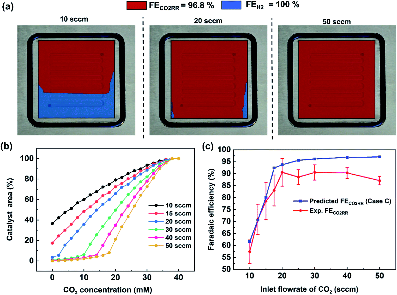
Product quantification within gaseous-fed CO2 electrolyzers is presently performed by measuring the composition of the outlet gas phase using a gas chromatography (GC), and measuring the composition of the liquid electrolyte phases using nuclear magnetic resonance spectroscopy (NMR) or high performance liquid chromatography (HPLC). Such measurements provide a point-in-time ‘black box’ interpretation of the FE at a given flow rate, current density and configuration that can be monitored through periodic measurements (Fig. 1a). At elevated inlet flow rates where CO2 utilizations are low, the outlet gas stream remains >90% CO2 and it is subsequently assumed that ample CO2 can reach the entire catalytic surface area. In other words, no specific area of the catalyst surface exhibits mass transport limitations and the faradaic efficiency is assumed to be equal across the entire catalyst area (e.g. FE ≠ f(x,y)). Such an assumption is particularly valid for smaller catalyst areas, high CO2 flow rates and open cavity gas channels which are assumed as well-mixed and maintained at similar temperature and pressures.As industrial and lab geometric cell areas increase, CO2 must be distributed to the GDL and catalyst area through flow fields, which are also critically acting as a current collector to ensure homogenous electrode potentials. Within these CO2 flow channels, the reactant and product compositions will then change along the length of each flow channel25 as the catalyst consumes CO2 and produces products such as CO and H2. In cases where CO2 utilizations are increased, spatial variations in performance and selectivity will occur when areas of the catalyst no longer have access to sufficient CO2, and produce unwanted H2 instead (see Fig. 1b for representation).26–28 To begin assessing this trade-off we first collected a data set under varying flow rate conditions for CO2 conversion to carbon-monoxide (CO) on a silver (Ag) catalyst in a membrane-electrode assembly with a serpentine flow field of 5 cm2 geometric area (Fig. S2†).
For the data set we performed electrolysis at a constant current density of 200 mA cm−2 for 3600 seconds at inlet CO2 flow rates between 10 and 50 sccm. The gas products and unreacted CO2 were quantified using a mass-flow metre (MFM) and GC installed at the exit of the reactor (Fig. 1a). As shown in Fig. 2a, we found that at excess flow rates between 20 and 50 sccm the faradaic efficiency of CO2 reduction products (CO and formate) was maintained between 93–97%, indicating that sufficient reactant is available throughout the system. At lower flow rates (<20 sccm), however the FE of hydrogen begins increasing steadily with increasing CO2 utilization, reaching an H2 selectivity of 38.9% at 10 sccm and a measured CO2 utilization of ∼50% (Fig. 2b). Over the entire examined region, CO2 utilization decreases with an increase in the inlet flow rate from 50.8% at 10 sccm to 16.8% at 50 sccm as shown in Fig. 2b. The highlighted grey region in Fig. 2a and b represents the likely operating region of a commercial CO2 electrolyzer as it best balances selectivity and utilization. Understanding and quantifying the performance trade-off is necessary to manufacture performance curves for CO2 electrolyzers, similar to other applications where trade-offs exist (e.g. centrifugal pumps). Such data is essential for positioning CO2 electrolyzers within integrated process and cost models that assess a broad operational parameter space. Additionally, better design of the reactant flow fields and gas-diffusion layers may improve performance further.
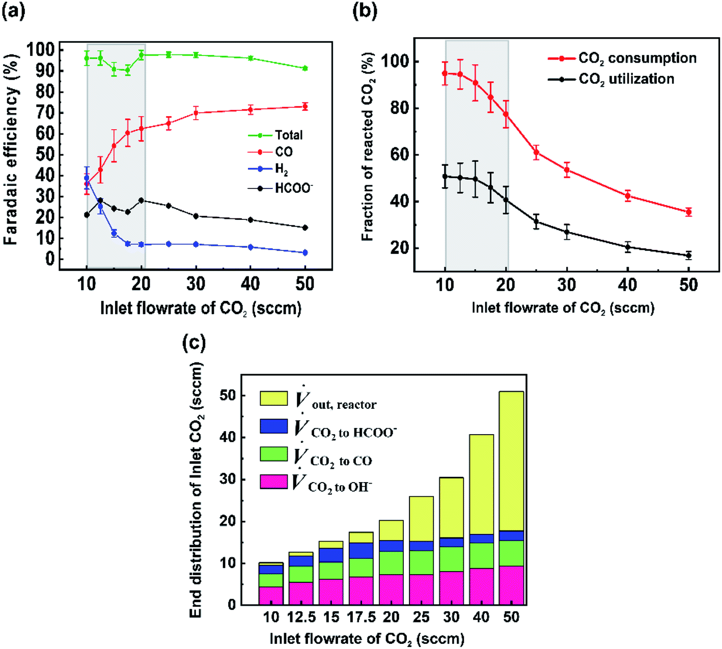 | ||
| Fig. 2 (a) Faradaic efficiency of products for various inlet flow rates performed at a current density of 200 mA cm−2. (b) CO2 utilization and CO2 consumption for different inlet flow rates at 200 mA cm−2. Greyed regions represent trade-offs between utilization and selectivity. (c) Carbon balance on cathode showing the volumetric flow rate of CO2 consumed to different reactions. Error bars represent the systematic error of the mass flow meter. | ||
To better quantify the trade-off in utilization and selectivity, the available CO2 for reduction in the system must be known. To track this a carbon balance of the system is performed at various flow rates (Fig. 2c). In this analysis the inlet and outlet flow rates of CO2, CO and formate are all measured directly, with the exception of CO2 crossing the membrane as carbonate ions which was assumed to complete the carbon balance. Observing the trends in carbon flow rates, two interesting points arise. First, even under low flow rates of 10 sccm, some CO2 is observed in the outlet of the reactor (∼5%/v) even though the reaction appears CO2-limited. This indicates a measure of transport limitations between the serpentine gas channel and the catalyst's surface as a result of transport through the gas-diffusion media and into the catalyst layer. And second, the consumption of CO2 by OH− ions is non-linear and varies with the availability of CO2 throughout the reactor. Both of these observations can be qualitatively interpreted from the presented data, but lack a quantitative interpretation in their present form as a result of the ‘black box’ measurement approach. Thus, a numerical transport model built upon the experimental results can be used to provide further understanding.
Modelling CO2 spatial distribution
To gain deeper understanding of the reactant distribution inside the reactor, a 3D model of the mass transport and fluid flow in the cathode compartment of the MEA cell was created using COMSOL Multiphysics (Fig. 3a). The ultimate goal of the model is to provide a simple estimate of the concentration of CO2 at the surface of the catalyst layer for various operating conditions, which can then be used to predict a spatial and average faradaic efficiency (FE = f(x,y) and FEaverage). The predicted average FE of the system in particular provides a comparison to the experimental data, while the spatial assessment is useful to advance performance further and for the design of scaled systems beyond 5 cm2.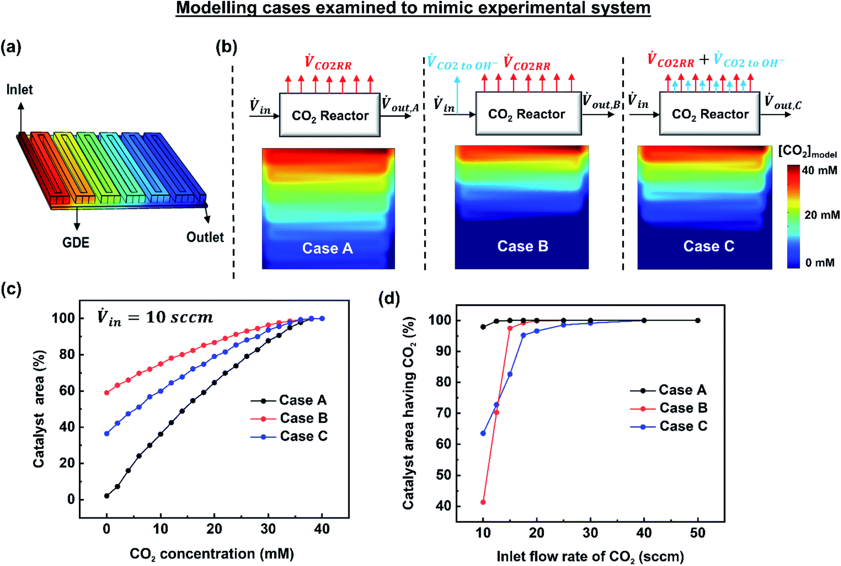 | ||
| Fig. 3 (a) 3D model of the flow channel and gas diffusion electrode. (b) Modelling cases examined to mimic the experimental observations. Shown here are the simulation results of CO2 concentration at the catalyst surface for an inlet flow rate of 10 sccm and 200 mA cm−2, (c) a cumulative distribution plot for the three cases showing the [CO2] distribution at the catalyst surface, (d) portion of catalyst surface having access to CO2 ([CO2] > 0) for all the inlet flow rates studied experimentally. | ||
Included within the model are the CO2 serpentine gas channel and a gas-diffusion layer composed of a carbon fibre backing and a microporous layer (Fig. S6†). The gas-diffusion electrode is then modelled as a porous media similar to other works.29 In the model an inlet flux of CO2 is provided to the system in the gas channel, while a fixed current density is imposed at the surface of the gas-diffusion electrode to model the electrochemical reactions and consumption of CO2 by the electrolyte. The physical parameters and properties used in the model are shown in Table S6.†
Due to the complexity of constructing a fully-representative macroscopic and nanoscopic transport model, we have chosen to set our system boundaries at the interface of the microporous layer and the catalyst layer. The model then does not directly take into account the interaction between the catalyst layer and the membrane, 3D transport effects within the nanopores of the catalyst layer, or the homogenous CO2/HCO3−/CO32− reactions occurring within the liquid water and Sustainion membrane. To account for this we have constructed three modelling scenarios using experimental mass flows as inputs to construct different empirical models that highlight the effect of different scenarios on CO2 distribution. The most representative system is then used to continue the discussion on CO2 utilization and faradaic efficiency.
The three examined cases are as follows: in Case A, we ignore the fraction of CO2 reacting with hydroxide ions. In Case B, the amount of CO2 lost to hydroxide ions is subtracted at the inlet resulting in a reduced inlet flow rate. In Case C, the fraction of CO2 lost to hydroxide ions is assumed to occur homogenously throughout the catalyst surface. These three cases are visually depicted in Fig. 3b along with their resulting simulated CO2 concentrations at the catalyst layer interface at 10 sccm and 200 mA cm−2. Fig. 3c shows the analysed data set from Fig. 3b represented as a cumulative distribution function for the percentage of the catalyst area with a minimum concentration of CO2.
Of note, using a modified inlet flow rate would also slightly impact the fluid velocity and pressure drop between the inlet and outlet, altering the actual physical phenomena occurring inside the reactor. Such an approach would then have significant effects when large flow rates are used where a significant pressure drop might exist between the inlet and outlet of the reactor. Critically, Case B over penalizes the CO2 concentration throughout the majority of the reactor as CO2 lost to OH− ions near the exit of the reactor has been removed prior to the reactor inlet.
 | (1) |
 | (2) |
Once imposed, Case C provides the spatial distribution of CO2 observed in Fig. 3b for an inlet flow rate of 10 sccm. Translating this to the cumulative distribution function in Fig. 3c, the net catalyst area with no access to CO2 is approximately 37%. Further, Fig. 3d shows the percentage of catalyst area with access to reagent results for all of the simulated cases and flow rates. Notably at flow rates within the utilization area of interest (10–20 sccm), Case C falls in between Cases A and B. The effect of parasitic CO2 loss is still not eliminated above 20 sccm, however, which can be attributed to poor CO2 access on the fringes of the gas-diffusion layer. In this case, this is due to the area of the GDE (6.25 cm2) expanding beyond the edge of the serpentine flow channel (5 cm2). Due to accounting for spatial effects, Case C is chosen as the most representative model for the remainder of the work.
Predicted spatial and average faradaic efficiency
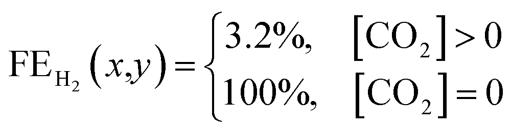
The previous section provided a set of models to predict the spatial concentration of CO2 within an experimentally-tested membrane-electrode assembly reactor. As the primary focus is to better understand the trade-offs between selectivity and utilization in these systems, these predicted concentrations of CO2 must be translated to a predicted spatial and average faradaic efficiency. To accomplish this we imposed the following selectivity criteria in eqn (3) and (4) based upon the predicted CO2 concentration, and the experimentally-measured faradaic efficiency under an excess CO2 flow rate of 50 sccm (97% CO2RR/3% HER). The data has been normalized to 100% (96.8% CO2RR/3.2% HER) for the purposes of the model. | (3) |
 | (4) |
Using this criteria, the spatial faradaic efficiency across the catalyst layer of the GDE is visually shown in Fig. 4a for three different flow rates. Observing the low flow rate case of 10 sccm, the loss of selectivity towards CO2RR is shown to be primarily due to insufficient CO2 along the length of the reactor towards the outlet. In the 20 sccm case, however, it is only the edges near the outlet of the reactor that are expected to primarily produce H2 instead of CO2RR products. The plots in Fig. 4a for spatial selectivity are predicated on the assumption that there is not a transition region of selectivity between the shown blue and red regions. In an actual system the switch in selectivity from primarily CO2RR to H2 along the reactor of CO2-deficient system would be more gradual, but high selectivities are known to be possible even at lower partial pressures.30 A secondary check of the approach is to translate the spatially-predicted faradaic efficiency into a device-averaged FE like that reported experimentally.
 | ||
| Fig. 4 (a) CO2 concentration map at the catalyst surface determined from the numerical simulations showing the spatial CO2 distribution at various inlet flow rates, (b) a cumulative distribution plot of CO2 concentration at the catalyst surface for different inlet CO2 flow rates studied using a modified current density approach and (c) comparison of predicted faradaic efficiency of CO2RR with experimentally determined faradaic efficiency (FECO + FEHCOO−). | ||
The device-averaged FE can be calculated by using the distribution function in Fig. 4b for a variety of different flow rates, and combining this with the criteria presented in eqn (1) and (2). The resulting predicted FE of CO2RR and H2 for all the inlet flow rates studied are then shown in Fig. 4c, with the experimentally-measured values overlaid. It can be seen clearly that the predicted FE is in close agreement with the experimental FE of CO2RR, showing the promise for using predicted CO2 distribution within the reactor to predict spatial and average device selectivity. The consistent over prediction can be attributed to the experimental FE's being less than 100%, most likely due to the inability to capture all produced formate in MEA cell. Importantly both the trend in selectivity within the higher CO2 utilization region (10 to 20 sccm), as well as in the lower utilization range (20–50 sccm), follow the experimental data set well. Such a model forms the foundation for comparing GDE's with different permeability, flow fields with different geometries, and the trade-offs with selectivity and utilization under different current densities.
The model can also be used to draw new observations from the experimental data set. For example, the incremental change in CO2RR from 20–50 sccm is shown to be due to a CO2 deficiency on the outer edges of the domain where the larger gas-diffusion layer (6.25 cm2) loses access to CO2 from the 5 cm2 serpentine channel area (see 20 sccm plot in Fig. 4a). Such an area then only produced H2, which slightly lowers the “black box” measured FE via gas chromatography. We are then able to predict the location on the catalyst surface where CO2 limitation occurs, which can help in understanding and designing flow channel designs at the cathode.
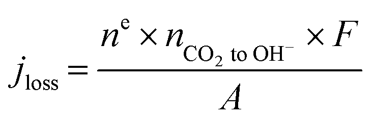
Finally, we emphasize here that at an applied current density of 200 mA cm−2, there is an increase in the amount of CO2 reacting with OH− ions with an increase in the reactant flow rate, which is identified in the increase in the jloss value (Table S2†). This is quite reasonable since the local OH− ions generated at 200 mA cm−2 is a constant (1.3 × 10⁻⁵ mol s−1) and an increase in the local CO2 concentration due to increased inlet flow rate shifts the reaction to the right producing more HCO3− and CO32− ions. Moreover, this reduction in local [OH−] with increasing inlet flow rates would also reduce the local pH altering the reaction environment around the catalyst surface. A further increase in inlet flow rate (60–100 sccm) would result in the consumption of all the OH− ions generated at the catalyst producing more HCO3− and CO32− ions with a subsequent alteration of the local reaction environment. Operating at such high reactant flow rates would however reduce the CO2 utilization to less than 10% and also increase the pressure drop between the inlet and outlet (serpentine channel) resulting in an increased pumping power.31 Hence, optimizing the reactant flow rate to overcome CO2 mass transport losses as well as ensuring a high CO2 utilization and a low pressure drop is a challenge. Therefore, we restricted our focus of this study to flow rates of up to 50 sccm.
Formate production from Ag GDE
While much of the work here focused on the availability of CO2 and the subsequent CO2RR selectivity as a result of this, the experimental data set noted interesting and opposing trends in CO and formate selectivity under a variety of flow rate conditions (Fig. 2a). In particular while overall CO2RR versus HER trended downward as flow rates decreased as could be expected (Fig. 5a), the selectivity of CO to formate also followed a similar linear trend, both within the CO2-limited and non-limited flow rate regions (Fig. 5b). Here, we briefly contextualize these results and offer possible explanations given previous literature reports and our spatial model constructed here. It is worth noting that to measure formate we performed HPLC measurements of the anolyte samples post electrolysis for our Ag GDE system, meaning that only formed formate which crossed the anion exchange membrane could be measured, likely explaining some missing FE in our data set. We will provide speculation in spite of this. | ||
| Fig. 5 (a) Ratio of partial current densities of CO2 RR (CO + HCOO−) and H2. Partial current densities of CO and formate with (b) varying inlet CO2 flow rates and (c) catalyst area with CO2 access. | ||
The trend in CO to formate within the two flow rate regions have two possible explanations from literature: (i) the reaction pathway to formate exists through surface-adsorbed protons and competition with HER, (ii) formate selectivity supplants some CO selectivity under higher alkalinity conditions. The first point has been reported previously by Bohra et al.32 using DFT calculations which showed that *OCHO towards formate forms through a bound *H, whereas CO formation proceeds first through direct CO2 absorption. Thus, formate formation requires the Volmer step from HER formation in order to be formed. It would then be expected to see a lower CO/formate ratio when *H is more common, which would be the case in decreased and depleted CO2 conditions like those observed from 10 to 20 sccm. Regarding (ii), previous studies on GDE flow cells have shown increased formate/CO ratios under extremely alkaline conditions (11 M KOH in Seifitokaldani et al.33) and decreased formate/CO ratios under higher CO2 pressures (Gabardo et al.34). Both reports indicate that the pH of the reaction environment will influence the ratio of CO to formate produced. Within our system, this hypothesis could help to explain the decreasing trend in formate production as the inlet flow rate ranges from 20–50 sccm. At higher flow rates excess CO2 is available to negate the formed OH− from the fixed current density reaction (see VCO2 to OH− blocks in Fig. 2c). It is then likely that the reaction environment surrounding the catalyst layer leans to lower alkalinities at 50 sccm versus that of 20 sccm, even though ample CO2 is available in both cases. The experimental decrease in jHCOO− is also seen when the model and experiments are combined (Fig. 5c), where formate current density drops when the full catalyst area has access to CO2.
Operating feed rate for larger cells at high current densities
Within this study a serpentine flow channel was utilized to provide CO2 to a 6.25 cm2 catalyst area. The experimental and modelling results can be extended to reactor areas of various sizes and current densities, presuming the dominating phenomena are not altered by doing so. Here we first provide a calculation for the required flow rate of CO2 to balance utilization while maintaining higher CO2 reduction selectivity. We then comment on the important phenomena to consider in scale-up regarding CO2 feed rate.To formulate the operating CO2 feed which best balances CO2 utilization and device selectivity for a given electrode area and current density, we utilized our 20 sccm flow rate as a base case. From Fig. 4a, the 20 sccm case best balances CO2 utilization (40%) and CO selectivity. Normalizing this flow rate with the geometric surface area of the GDE (6.25 cm2) and partial current density of CO (125 mA cm−2), we predict that the operating reactant feed for industrial operation should be 0.0256 cm3 min−1 mA−1. We compared this value with a study from Endrődi et al.14 where a similar study using Ag GDE in a zero gap CO2 electrolyzer at 1 A cm−2 was performed. In their study, a large geometric surface area of 100 cm2 was employed and a feed rate of 12.5 cm3 min−1 cm−2 was used to obtain the same CO2 utilization of 40%. Normalizing this feed rate to their CO partial current density (630 mA cm−2), the operating feed comes to 0.0198 cm3 min−1 mA−1 which agrees closely with our predicted value.
From the modelling studies performed we can comment that a number of factors would change the flow rate of CO2 required at the reactor inlet. Specifically, while the inlet flow rate can be well controlled, diffusion of CO2 from a gas channel into the liquid immersed catalyst layer is less tuneable and will be impacted by such things as specific device configuration, the catalyst thickness and deposition type, pressure drop within the system, temperature, etc. As reactors scale to larger and larger sizes these factors may alter the ideal CO2 feed rate. For example, for large reactors larger pressure drops in the gas-phase will occur if singular serpentine channels are used as the gas may prefer to shortcut under the gas channel and through the gas-diffusion layer. This would then result in a higher degree of under-rib convection changing localized CO2 concentrations from the 6.25 cm2 reactor. Thus, when moving from smaller to larger reactors, proper engineering design is needed to ensure that local phenomena are maintained near their ideal conditions, even as the reactor scales up.
Conclusion
The balance between CO2 utilization and selectivity with electrochemical systems will be ever more important as CO2 electrolyzers are scaled to larger areas and considered within larger chemical processes due to implications they have on reliability, separation processes and system costs. The trade-offs in these metrics are currently measured and reported for an entire reactor, while being driven by spatial variation in concentrations across an entire electrochemical reactor. At present, the experimental ability for direct localized measurement of CO2 electrolysis products has not been demonstrated however. The work presented here aims to predict this trade-off by pairing bulk product measurement with a transport model to provide a measure of spatial resolution to our electrochemical cell. We believe that our approach can provide a starting point for a more extensive modelling study to enhance the understanding of the local reaction environment around the catalyst surface in a membrane electrode assembly configuration, employing anion exchange membranes. Importantly, we hope this work inspires experts from adjacent fuel cell community to provide their wealth of experience to accelerate the CO2 reduction field forward.Author contributions
S. S. completed all of the experiments and modelling work. J. M. setup the experimental apparatus and assisted with experimental issues. T. B. and S. S. conceived the project. All authors contributed to writing and editing of the manuscript.Conflicts of interest
There are no conflicts to declare.Acknowledgements
Thomas Burdyny and Siddhartha Subramanian would like to acknowledge the co-financing provided by Shell and a PPP-allowance from Top Consortia for Knowledge and Innovation (TKI's) of the Ministry of Economic Affairs and Climate in the context of the TU Delft e-Refinery Institute. TB would also like to acknowledge the NWO for an individual Veni grant. The authors would also like to acknowledge Mark Sassenburg for HPLC analysis and Sanjana Chandrasekar, Erdem Irtem and all members of Burdyny Energy lab for helpful discussions.References
- Y. Hori, Electrochemical CO2 reduction on metal electrodes, Springer, NY, 2008, pp. 89–189 Search PubMed.
- W. Tang, A. Peterson, A. Varela, Z. Jovanov, L. Bech, W. Durand, S. Dahl, J. Nørskov and I. Chorkendorff, Phys. Chem. Chem. Phys., 2012, 14, 76–81 RSC.
- Y. Hori, I. Takahashi, O. Koga and N. Hoshi, J. Phys. Chem. B, 2002, 106, 1–17 CrossRef.
- C. Dinh, T. Burdyny, M. Kibria, A. Seifitokaldani, C. Gabardo, F. De Arquer, A. Kiani, J. Edwards, P. De Luna, O. Bushuyev and C. Zou, Science, 2018, 360, 783–787 CrossRef CAS PubMed.
- D. Gao, R. Arán-Ais, H. Jeon and B. Cuenya, Nat. Catal., 2019, 2, 198–210 CrossRef CAS.
- W. Smith, T. Burdyny, D. Vermaas and H. Geerlings, Joule, 2019, 1822–1834 CrossRef CAS.
- O. Sánchez, Y. Birdja, M. Bulut, J. Vaes, T. Breugelmans and D. Pant, Curr. Opin. Green Sustain. Chem., 2019, 16, 47–56 CrossRef.
- T. Burdyny and W. Smith, Energy Environ. Sci., 2019, 12(5), 1442–1453 RSC.
- M. Kibria, J. Edwards, C. Gabardo, C. Dinh, A. Seifitokaldani, D. Sinton and E. Sargent, Adv. Mater., 2019, 31, 1807166 CrossRef PubMed.
- G. Larrazábal, A. Martín and J. Perez-Ramirez, J. Phys. Chem. Lett., 2017, 8, 3933–3944 CrossRef PubMed.
- S. Ma and P. Kenis, Curr. Opin. Chem. Eng., 2013, 2, 191–199 CrossRef.
- D. Higgins, C. Hahn, C. Xiang, T. Jaramillo and A. Weber, ACS Energy Lett., 2018, 4, 317–324 CrossRef.
- D. Whipple, E. Finke and P. Kenis, Electrochem. Solid-State Lett., 2010, 13, B109 CrossRef CAS.
- B. Endrődi, E. Kecsenovity, A. Samu, T. Halmágyi, S. Rojas-Carbonell, L. Wang and C. Janáky, Energy Environ. Sci., 2020, 13, 4098–4105 RSC.
- F. De Arquer, C. Dinh, A. Ozden, J. Wicks, C. McCallum, A. Kirmani and E. Sargent, Science, 2020, 367, 661–666 CrossRef PubMed.
- E. Jeng and F. Jiao, React. Chem. Eng., 2020, 5, 1768–1775 RSC.
- M. Ma, E. Clark, K. Therkildsen, S. Dalsgaard, I. Chorkendorff and B. Seger, Energy Environ. Sci., 2020, 13, 977–985 RSC.
- C. Gabardo, C. O'Brien, J. Edwards, C. McCallum, Y. Xu, C. Dinh, J. Li, E. Sargent and D. Sinton, Joule, 2019, 3, 2777–2791 CrossRef CAS.
- W. Smith, T. Burdyny, D. Vermaas and H. Geerlings, Joule, 2019, 3, 1822–1834 CrossRef CAS.
- G. Kyriacou and A. Anagnostopoulos, J. Appl. Electrochem., 1993, 23, 483–486 CrossRef CAS.
- S. Dutta, S. Shimpalee and J. Van Zee, J. Appl. Electrochem., 2000, 30, 135–146 CrossRef CAS.
- P. Futerko and I. Hsing, Electrochim. Acta, 2000, 45, 1741–1751 CrossRef CAS.
- Z. Wang, C. Wang and K. Chen, J. Power Sources, 2001, 94, 40–50 CrossRef CAS.
- J. Nam, K. Lee, S. Sohn and C. Kim, J. Power Sources, 2009, 188, 14–23 CrossRef CAS.
- L. Rostami, P. Nejad and A. Vatani, Energy, 2016, 97, 400–410 CrossRef CAS.
- C. Bondue, M. Graf, A. Goyal and M. Koper, J. Am. Chem. Soc., 2020, 143, 279–285 CrossRef PubMed.
- H. Ooka, H. M. Figueiredo and M. Koper, Langmuir, 2017, 33, 9307–9313 CrossRef CAS PubMed.
- D. Raciti, M. Mao and C. Wang, Nanotechnology, 2017, 29, 044001 CrossRef PubMed.
- D. Wheeler, B. Mowbray, A. Reyes, F. Habibzadeh, J. He and C. Berlinguette, Energy Environ. Sci., 2020, 13, 5126–5134 RSC.
- H. Song, J. Song, B. Kim, Y. Tan and J. Oh, Appl. Catal., B, 2020, 272, 119049 CrossRef CAS.
- D. Jeon, S. Greenway, S. Shimpalee and J. Van Zee, Int. J. Hydrogen Energy, 2008, 33, 1052–1066 CrossRef CAS.
- D. Bohra, J. Chaudhry, T. Burdyny, E. Pidko and W. Smith, Energy Environ. Sci., 2019, 12, 3380–3389 RSC.
- A. Seifitokaldani, C. Gabardo, T. Burdyny, C. Dinh, J. Edwards, M. Kibria, O. Bushuyev, S. Kelley, D. Sinton and E. Sargent, J. Am. Chem. Soc., 2018, 140, 3833–3837 CrossRef CAS PubMed.
- C. Gabardo, A. Seifitokaldani, J. Edwards, C. Dinh, T. Burdyny, M. Kibria, C. O'Brien, E. Sargent and D. Sinton, Energy Environ. Sci., 2018, 11, 2531–2539 RSC.
Footnote |
| † Electronic supplementary information (ESI) available. See DOI: 10.1039/d1se01534f |
| This journal is © The Royal Society of Chemistry 2021 |