
 Open Access Article
 This Open Access Article is licensed under a
 Creative Commons Attribution 3.0 Unported Licence
Revisiting the promise of Bi-layer graded cathodes for improved Li-ion battery performance†
Ridwanur
Chowdhury
 a,
Yan
Zhao
b,
Yuhua
Xia
a,
Mengzheng
Ouyang
*a,
Nigel
Brandon
a and
Aayan
Banerjee
c
a,
Yan
Zhao
b,
Yuhua
Xia
a,
Mengzheng
Ouyang
*a,
Nigel
Brandon
a and
Aayan
Banerjee
c
aDepartment of Earth Science and Engineering, Imperial College London, London SW7 2BP, UK. E-mail: m.ouyang15@imperial.ac.uk
bDepartment of Mechanical Engineering, Imperial College London, UK
cCatalytic Processes and Materials, Faculty of Science and Technology, University of Twente, Netherlands
First published on 10th September 2021
Abstract
Improving power and energy density by grading electrode microstructures is a promising topic in the field of battery electrode engineering. While previous modelling studies have predicted both considerable and marginal improvements in cell performance, very few experimental studies have been conducted to validate the performance of graded electrodes. In this article, we report on the fabrication of a bi-layer graded lithium-ion battery cathode by varying both the particle size and the porosity in each layer. Structural analyses were carried out via 2D (scanning electron microscopy (SEM) and energy dispersive X-ray spectroscopy (EDX)) and 3D (X-ray computed tomography (XCT) and focused-ion beam tomography (FIB)) imaging techniques. The bi-layer cathode (BLC) exhibits an increase of 62.8% in discharge capacity at 2C compared to a conventional single layer electrode. The polarization and electrochemical impedance spectroscopy data indicate that the improved capacity performance of the BLC can be attributed to reduced charge transfer resistance and increased solid phase diffusivity. However, capacity retention performance reveals that the BLC retained no advantage over a conventional electrode in a half-cell configuration after 100 cycles. At 1C, the BLC displayed only minimal improvement in power (4.6%) and energy (7.6%) density based on first discharge capacity. As such, noting the extra challenges involved in manufacturing such graded electrode structures, it is recommended that their use is best focused on higher C rate applications and that more work is needed to demonstrate the retention of the higher C rate performance gain over multiple cycles.
1. Introduction
Lithium-ion batteries (LIBs) have been considered as one of the most promising energy storage systems since their introduction into the consumer electronics market by Sony Corporation in the early 1990s.1 LIBs have been used in a wide range of portable electronic devices including laptops, cell phones, medical implants, power tools, and other modern-life appliances.2,3 In recent years, LIBs have been recognized as playing an integral part in the advancement and large-scale deployment of electric vehicles (EVs).4 The future of electric vehicles (EVs) lies in the manufacture of LIBs, which have both high energy density (determines the single charge maximum mileage) and high-power density (determines the maximum average acceleration and speed). Thick electrodes can increase energy density through the use of a high active material (AM) loading. However, this increase in energy density comes at the expense of power density because of sluggish charge transfer kinetics and longer distances for lithium ions to transport across the electrode thickness.5,6Several strategies have been proposed to improve power–energy combinations including introducing new materials, modifying the surface of existing materials, and the microstructural engineering of electrodes.2,7,8 The latter strategy avoids changes in battery chemistry and is the focus of this research. One of the promising avenues for electrode engineering is grading an electrode by spatially varying microstructures (i.e. porosities and/or particle sizes) or compositions (i.e. concentration of AM and/or conductive additives). To date, most of the reports on graded electrodes have focused on the modelling effort to predict cell performance.9–15 Simulation results show mixed results, with both significant benefits9,10,13,14 and only marginal improvement11,15 reported for electrodes with graded architectures compared to conventional electrodes with single sized particles and constant porosity, depending on the design parameters and range of conditions evaluated.
Very few researchers have investigated graded electrodes through experiments to validate the simulation results.16–23 Huang et al. synthesized a thin (12.2 μm) TiO2 graded anode structure with two discrete layers fabricated by spray deposition.16 The top layer closer to the separator was a nonporous (pore size not reported) material consisting of a particle size of 25 nm and the bottom layer closer to the current collector (CC) was a porous material consisting of a particle size of 200 nm and a pore diameter of 40 nm. Their experimental results confirmed superior volumetric charge (Li extraction) capacity and coulombic efficiency at high current density (2C and 4C) for this bi-layer electrode compared to single layer P–TiO2 and N–TiO2 electrodes. In later work, Huang et al. synthesized both LiCoO2 and LiFePO4 cathodes with aligned pore channels by an ice templating method to promote fast liquid phase ion transport through the electrode thickness.17,18 Such porosity gradient-based electrodes exhibit 57% (ref. 17) and 67% (ref. 18) higher gravimetric energy density at high C-rates compared to conventional electrodes with random microstructures. Liu et al. investigated a 166 μm thick bi-layer porosity-graded cathode with both layers composed of the same particle size (∼0.5 μm).19 The graded LiNi0.5Mn1.5O4 structure had a porosity of 34% and 23% in its top layer and bottom layer respectively. By grading the electrode, the capacity fade was reduced by ∼5.3% in half-cells compared to a single layer electrode with constant porosity. Furthermore, EIS measurements on full cells confirmed a reduction in both film (Rf) and charge transfer (Rct) resistance for the porosity-graded design. Very recently, Song et al. manufactured a similar porosity graded LiNi0.8Co0.15Al0.05O2 electrode by employing a combination of slurry casting and electrostatic spinning techniques.23 This 145 μm bi-layer cathode retained a ∼35.6% and ∼45.6% higher discharge capacity at 0.5C after 50 cycles compared to other electrodes fabricated by diverse approaches.
Liu et al.20 and Cheng et al.21,22 expanded the domain of electrode engineering from microstructural grading to compositional grading. Liu et al. applied slot die-coating technology to manufacture 100 μm thick bi-layer LiNi0.4Mn0.4Co0.2O4 cathodes with different binder compositions in each layer. Cheng et al. synthesized composition graded cathodes (LiFePO4) and anodes (Li4Ti5O12) with thicknesses ranging from 81 μm to 143 μm with the aid of the same spray deposition equipment used in ref. 16. The benefits of such graded structures over conventional electrodes include a reduced capacity degradation rate (<50% at 1C (ref. 22) and 40–50% at 2C (ref. 21)), increased discharge capacity (120% at 1C,22 31% at 2C,21 and ∼7.6% at 0.1C (ref. 20)), and an improved power–energy density balance.
To the authors' knowledge, none of the previous experimental studies on microstructural graded electrodes have fabricated and evaluated the performance of thick layered cathode structures (≥180 μm) by varying both particle sizes and porosities along the electrode thickness. In this work, we report on a novel bi-layer structure in which the manufactured graded design comprises two distinct particle sizes and porosities in adjacent layers. In addition, this work reports the thickest bi-layer electrode (∼200 μm) that has been fabricated and characterized to date. The underutilization of the AM near the CC owing to Li+ depletion in the liquid phase and/or Li+ diffusion gradients in the AM particles is one of the main reasons for power fade in thick electrodes (≥104 μm).6,12,24–26 Therefore, the justification of such bi-layer electrode engineering is to facilitate Li+ transport in both the solid and the liquid phase simultaneously through graded particle size (diffusion length) and graded porosity respectively.
Our previous modelling work on graded cathodes predicted that higher electrode utilization (next to the CC) and discharge capacity at higher C-rates (1–4C) can be achieved by positioning large particles with higher porosity in a layer next to the separator and small particles with lower porosity in a layer next to the CC.27 Such a bi-layer design exhibited an increase of 47.7% in energy density without compromising power density compared to a conventional single layer electrode consisting of big particles at 4C. Motivated by these promising results, we have manufactured a bi-layer cathode with the aim of evaluating its performance against our simulation results. A schematic of the microstructure with two layers composed of two distinct particle sizes is illustrated in Fig. 1. As a follow-up to our modelling work, we have carried out experimental work and have applied insights from our simulations to help analyze cell performance.
 | ||
| Fig. 1 A schematic illustration of a bi-layer cathode consisting of two distinct particle sizes in each layer. | ||
In this article, first the effect of the material processing conditions on the LiNi0.5Mn0.3Co0.2O2 (NMC532) particle size and crystal structure is investigated. Next the as-received and the processed materials are used to manufacture bi-layer and single layer cathodes. Scanning electron microscopy (SEM), energy dispersive X-ray spectroscopy (EDX), focused-ion beam (FIB) tomography and X-ray computed tomography (XCT) are utilized for structural analysis. The electrochemical performance of the bi-layer cathode is compared with that of single layer cathodes. The kinetic and transport behaviors of the electrodes are studied using EIS. Finally, the benefits of grading microstructures are contrasted against the constraints associated with their synthesis through a traditional slurry-casting method.
2. Experimental
2.1 Materials
NMC532 powder samples and Li chips (15.6 mm diameter) were provided by MTI Corporation. Carbon black (Super C-65) was provided by TIMCAL. Polyvinylidene difluoride (PVDF) binder, 1-methyl-2-pyrrolidinone (NMP) and 1 M LiPF6 in EC![[thin space (1/6-em)]](https://www.rsc.org/images/entities/char_2009.gif) :EMC (1:1) were purchased from Sigma Aldrich. Low viscosity carbon epoxy (C-epoxy) resin EpoFix and curing agent EpoFix Hardener were provided by Struers.
:EMC (1:1) were purchased from Sigma Aldrich. Low viscosity carbon epoxy (C-epoxy) resin EpoFix and curing agent EpoFix Hardener were provided by Struers.
2.2 Material processing and Bi-layer electrode fabrication
The as-received NMC532 powder samples were wet ball-milled to break the large secondary particles into small primary particles. Aggressive ball-milling conditions (e.g., speed ≥ 650 RPM) are known to have detrimental effects on NMC structures.28,29 Previous reports have shown that the decrease in the crystallite size is not prominent for mild ball-milling conditions (speed ∼ 350 RPM and time ∼ 2 hours),28 the mechanically induced deformation in the layer structure can be prevented by avoiding excessive milling time,29 and the NMC materials processed under mild ball-milling conditions exhibit improved Li intercalation properties.28,30 Therefore, mild ball-milling conditions (milling speed: 350 RPM and milling time: 1 hour) were applied to break down the secondary particles. After the milling process, the samples were freeze dried to obtain powder samples with small particles. The single layer electrodes with big and small particles were fabricated by a slurry casting (SC) process. The electrode slurry was prepared by mixing NMC532 (80 wt%), carbon black (10 wt%), and PVDF (10 wt%), dissolved in NMP. The resulting slurry was then cast on a cleaned Al current collector. The electrode slurries with small and big particles were dried in an oven at 70 °C and 80 °C respectively for 10 hours. The further description of the slurry mixing process, the single layer electrode fabrication process, and the justification of choosing certain slurry compositions can be found in our previous work on LiNi0.8Mn0.1Co0.1O2 (NMC811).27 A recent study has revealed that Ni-rich NMC811 is prone to surface contamination during electrode processing because of its high surface reactivity under ambient air exposure, leading to rapid capacity fade.31 Hence, to avoid the interference from impurities on cycling performance, lower Ni-content NMC532 was chosen as the cathode material to investigate the microstructural grading affect.The bi-layer electrodes were manufactured by a two-step SC and drying process. First, the first layer was fabricated by casting a slurry with a small particle size onto an Al current collector. The slurry was dried in an oven at 70 °C for 10 hours. The thickness of the first layer was measured using a micrometer. Afterwards, the second layer was fabricated by casting a slurry with a large particle size on top of the first layer. The second layer slurry was dried again in an oven at 80 °C for 10 hours. The total thickness of the cast and dried electrode was measured again.
The electrode thickness and corresponding mass loading of AM for bi-layer and single layer cathodes were measured based on 60 different cathode samples (20 samples per type) and are listed in Table 1. In this work, the bi-layer cathode is designated as BLC. Similarly, single layer cathodes with big and small particle sizes are designated as SLC1 and SLC2 respectively.
| Type of cathode | Each layer thickness (μm) | Total thickness (μm) | Mass loading of AM (g m−2) |
|---|---|---|---|
| BLC | 102 ± 8 | 201 ± 12 | 199.2 ± 13.5 |
| SLC1 | — | 198 ± 10 | 202.0 ± 10.2 |
| SLC2 | — | 213 ± 14 | 194.7 ± 9.8 |
The electrodes were un-calendered since this work aimed to avoid influencing the particle size distribution (PSD) and porosity in the microstructure through geometric compaction. Calendering improves electronic conductivity and adhesion between the electrode and the CC but increases tortuosity and charge transfer resistance at the interface of the electrode and electrolyte.32–34 An increased tortuosity results in higher transport resistance in the liquid phase that is not desirable in thick electrodes. In addition, it would be hard to justify any influence on charge transfer resistance due to microstructural grading as opposed to calendering. Furthermore, issues concerning the adherence and electronic conductivity in the uncalendered microstructures were addressed through the use of comparatively high CB and binder wt% in the slurry recipes. The wt% of AM, CB, and binder in the slurry recipe was kept the same for all three types of cathodes.
2.3 Coin cell construction
Disk-shaped electrodes with a diameter of 15 mm were punched out from the electrode sheet using a coin cell disc cutter. The cathode disks were dried for 12 hours at 120 °C in a vacuum oven to remove air and residual moisture and were transferred into an argon-filled glovebox (≤1 ppm, O2 and H2O levels).The single layer and bi-layer cathodes were assembled into CR2032 coin cells with a mono-layer membrane separator Celgard 2500, LiPF6 electrolyte and Li chip counter/reference electrodes. It has been reported that, in a coin-cell configuration, the key parameters that impact the cell performance include the cathode loading, the Li anode thickness and the amount of electrolyte.35 Therefore, careful consideration was given to those parameters during cell construction; otherwise, it would be difficult to determine whether the observed electrochemical performance is from those uncontrolled parameters or from the electrode engineering in the cells. Since the cell performance was evaluated against thick graded cathodes with a high mass loading, a thick (∼450 μm) Li chip and a higher amount of electrolyte (∼160 μL) were used to ensure sufficient Li resources in the cell.
The half-cell configuration used for assembling CR2032 coin cells is shown in Fig. S1(a).† Volume expansion occurs in both the Li metal and NMC when cycling the battery.36–38 Since a thicker Li metal compared to the NMC cathode is used to construct the cell, the spring is placed closer to the Li chip to alleviate mechanical stress induced by large volumetric expansion during Li plating.
2.4 Structural characterization
The SEM top and cross-sectional views of the processed materials and fabricated electrodes were imaged using a LEO Gemini 1525 SEM with a high-resolution field emission (FE) gun. EDX was used to investigate the qualitative elemental distribution across the thickness of the bi-layer structure. The EDX installed on the FE-SEM was an Inca X-act silicon drift detector (SDD) with a 10 mm2 chip from Oxford Instruments. A secondary electron (SE) detector with an accelerating voltage of 20 kV was used to obtain cross-sectional SEM images and EDX mapping along with line scans of the bi-layer microstructures with two layers consisting of two distinct particle sizes. Before slicing the microstructure for imaging, cathodes were embedded in epoxy resin via a vacuum impregnation technique that followed the steps reported elsewhere.39 Next, the samples were sliced using an Accutom-50 precision cutting machine equipped with a Struers diamond cut-off wheel (M0D15). These steps resulted in solidification and smooth cross-sectional slicing of the layered structures by preventing the collapse of the top layer (closer to the separator) on the bottom layer (closer to the CC).A Zeiss Auriga 40 focused-ion beam (FIB) scanning microscope equipped with a Gemini FE-SEM column was employed to resolve microstructures with small feature sizes. After applying an initial milling current of 16 nA to cut the volume of interest (VOI), a milling current of 240 pA was applied for slicing the volume with a depth of 20 μm. The pixel sizes and slice thickness of the acquired images were 22.5 nm × 22.5 nm and 40 nm respectively. An Energy Selective Backscattered (EsB) detector with an accelerating voltage of 1.5 kV was selected to achieve FIB-SEM image sequences with sharp phase contrast. Statistical image analysis and image processing were accomplished using the open-source software Fiji-ImageJ and several plugins. A Zeiss Xradia Versa 500 X-ray computed tomography (XCT) machine was used to quantify the porosity in SLC1 since microstructures with larger particle sizes require scanning of larger volumes to achieve statistical representation. The operating settings for the XCT instrument are presented in Table S1.†
Brunauer–Emmett–Teller (BET) analysis was performed using an Autosorb iQ3 gas sorption analyser from Quantachrome Instruments to determine the surface area of the ball-milled powder sample. A PANalytical X'Pert X-ray diffractometer with a Cu Kα radiation source and a step size of 2θ = 0.016 was employed to obtain the powder X-ray diffraction (XRD) patterns of the as-received and ball-milled samples.
2.5 Electrochemical characterization
The galvanostatic cycling performance of the fabricated electrodes was tested using a Landt Instruments CT2001A battery cycler system at different C-rates with a cut-off voltage between 2.7 V and 4.3 V. The electrochemical impedance spectroscopy (EIS) studies were conducted using a Bio-Logic SAS BCS-800 series battery cycler over the frequency range of 0.01 Hz to 100 kHz by applying a sinusoidal signal with an amplitude of 10 mV. Prior to EIS measurements, three complete formation cycles were carried out at 0.1C. EIS measurements were performed at the end of the discharge voltage 2.7 V. The experimental EIS data were fitted to an equivalent electric circuit (EEC) using EC-lab V11.12 software. All the electrochemical measurements were conducted at room temperature.3. Results and discussion
3.1 Particle morphology of the processed materials
The SEM images of the as-received and ball-milled NMC532 samples can be seen in Fig. 2(a) and (c) respectively. The SEM image in Fig. 2(c) reveals that big secondary spherical particles are broken into smaller primary non-spherical particles when ball-milled for 3 hours. The PSD of the big and small particles is shown in Fig. 2(b) and (d) respectively. The average particle diameter for big and small particles is ∼10 μm and ∼1 μm respectively, confirmed by statistical image analysis. A similar PSD was observed in our previous work on NMC811.27 The BET surface area of the milled powder sample is 15.2 m2 g−1. The reported BET surface area for the as-received powder sample is 0.2–0.4 m2 g−1. The tap density for the as-received large particles and the ball-milled small particles was found to be 2.43 and 0.69 g cm−3 respectively. The XRD pattern in Fig. S1(b)† shows the effect of ball milling on crystal structures. All the diffraction peaks can be identified based on previous XRD reports on NMC532.40–43 No phase change occurred due to material processing as both big and small particles show similar peaks and peak locations. The sharp diffraction peaks of big particles suggest their highly crystalline structures.28 On the other hand, small particles exhibit lower relative intensity and broadening of XRD peaks can be related to their relative decrease in crystallinity.28,30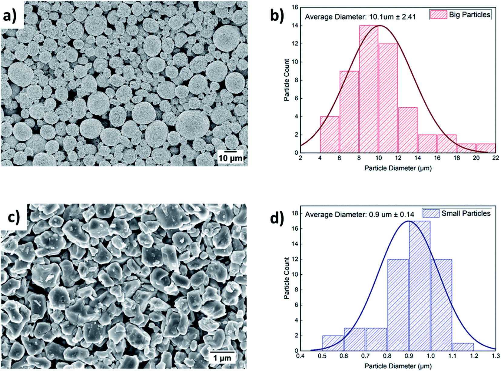 | ||
| Fig. 2 FE-SEM images of the (a) as-received secondary and (c) ball-milled primary NMC532 particles, and statistical image analysis of the PSD of the (b) as-received secondary and (d) ball-milled primary particles. | ||
3.2 Microstructure of Bi-layer cathodes
The cross-sectional SEM images of the BLC in low and high magnification can be seen in Fig. 3(a) and (e) respectively. The SEM images confirm the successful fabrication of bi-layer microstructures with two distinct layers consisting of small and big particles. As evidenced from the cross-sectional images, the layers are well connected, which ensures undisrupted charge transport pathways in the electrode thickness direction. Fig. 3(b) displays one of the big particles located in the top layer. The distribution of small particles in the bottom layer is also displayed in Fig. 3(c). These SEM images further confirm that the particle morphological (size and shape) integrity in each respective layer was not compromised by the two-step SC and drying process. The porosity in the layer with big particles is estimated by segmenting (Fig. S2†) the top layer of the cross-sectional SEM image presented in Fig. 3(e). 3D FIB tomography is performed to estimate the porosity in the layer with small particles as the quantification of porosity cannot be resolved from the cross-sectional 2D SEM images due to dense features. Both the cross-sectional SEM image and the FIB- SEM image stack were segmented into two phases (red is the solid phase and green is the pore phase) by employing the Trainable Weka Segmentation (TWS) tool,44 a machine learning based segmentation plugin of Fiji-ImageJ. The 3D microstructure of the bottom layer consisting of small particles is reconstructed by aligning the image stack of consecutive FIB slices and is illustrated in Fig. 3(d). Each side length of the reconstructed VOI is greater than 8 times the average diameter of the small particles, which suggests that the quantified property could be a representative value for the real electrode microstructure, also known as a representative volume element (RVE).45–47 The porosity for SLC1 and SLC2 is estimated by using XCT and FIB tomography respectively. The measured porosity difference (∼9%) between big and small particles is consistent with our previous report24 on the 3D image analysis of single layer electrodes carried out by XCT and FIB imaging techniques as well. Table 2 lists all the microstructural values along with characterization techniques that were used for quantification purposes. The 3D rendering of the reconstructed microstructures for SLC1 and SLC2 is presented in Fig. S3(b) and (d).† The top-view SEM images of BLC, SLC1 and SLC2 can be seen in Fig. 3(f), S3(a) and (c)† respectively. The SEM images confirm no significant aggregation of AM particles, migration of the binder, and deposition and agglomeration of CB particles at the electrode surface due to slurry drying conditions. The influence of slurry drying conditions on the electrode microstructure is elucidated in Section 3.4. The cross-sectional SEM-EDX mapping in Fig. 4 shows the distribution of active (Ni, Mg, Co, and O) and inactive (C) materials across the interface between two layers. The sources for C are the binder, the CB and the pores filled with C-epoxy resin. | ||
| Fig. 3 (a and e) Cross-sectional SEM image of the bi-layer cathode in low and high magnification. (b and c) Big particle in the top layer and distribution of small particles in the bottom layer. (d) A 3D rendering of the reconstructed layer with small particles. (f) Top-view SEM image of the bi-layer cathode. | ||
| Type of cathode | Microstructural values | Characterization technique | |||
|---|---|---|---|---|---|
| Average particle diameter | Porosity | Particle size | Porosity | ||
| BLC | Top layer | ∼10 μm | ∼54% | SEM | SEM |
| Bottom layer | ∼1 μm | ∼42% | SEM | FIB | |
| SLC1 | ∼10 μm | ∼52% | SEM | XCT | |
| SLC2 | ∼1 μm | ∼43% | SEM | FIB | |
 | ||
| Fig. 4 SEM-EDX elemental maps of the cross section of the bi-layer cathode. | ||
3.3 Electrochemical performance of Bi-layer cathodes
The specific discharge capacities of SLC1, SLC2, and BLC at different C-rates (0.5–2C) are compared in Fig. 5(a). Five formation cycles were carried out at 0.2C, followed by 10 consecutive cycles at the respective C-rate. The cycling data were acquired from 9 cells made from three different batches of electrode sheets of the same type; a total of 27 coin cells were tested for all three types (SLC1, SLC2, and BLC) of electrodes. Error bars are included to show the standard deviation in cell discharge capacities. At a low C-rate of 0.2C, both bi-layer and single layer electrodes show a similar discharge capacity of ∼156 mA h g−1 as all the electrodes hold about the same mass loading (Table 1) and the cell capacity is determined by the intrinsic capacity of NMC532.43,48 As the C-rate increases from 0.5C to 2C, the effect of microstructural features on charge transfer resistance and mass transport, along with the resultant deliverable capacity, becomes obvious. The discharge capacity for BLC and SLC2 exceeds that of SLC1 from 0.5C. At 1C, BLC and SLC2 exhibit an increase of 7.5% and ∼3.8% in discharge capacity respectively compared to SLC1. A rapid drop in discharge capacity for SLC1 (∼25.2 mA h g−1) can be noticed at 2C, whereas BLC and SLC2 were able to maintain a cell capacity of ∼41.3 and ∼38.2 mA h g−1. These variations in discharge capacities can be understood from our previous analysis of transport phenomena in simulated single layer and bi-layer structures.27 SLC1 has higher porosity throughout its electrode thickness that allows a greater amount of Li+ to be transported to the reaction zone next to the CC. Nevertheless, this conventional electrode suffers from overall underutilization of the AM (solid phase concentration) along the electrode thickness. This is because there is not enough time for Li+ to intercalate into the bigger particles due to their longer diffusion length, especially at high C-rates. SLC2 shows higher utilization of the AM closer to the separator, and hence a higher discharge capacity compared to SLC1 can be observed. This is related to the presence of small particles with a short diffusion length and large interfacial surface area, which contribute to higher rates of Li+ uptake. However, SLC2 suffers from underutilization of the AM closer to the CC because of the large depletion of lithium in the electrolyte next to the CC due to its lower porosity throughout the electrode thickness. On the other hand, the BLC design improves the Li+ uptake throughout the depth of the electrode via two contributing factors: the use of higher porosity in the top layer, which provides more Li+ access to the depth of the bottom layer and the use of small particles with a reduced diffusion length and increased interfacial surface area in the bottom layer, which increases the local uptake rate of transported Li+. Consequently, an overall better electrode utilization is observed that also translate into higher deliverable capacity. Fig. 5(b) and (c) display galvanostatic charge–discharge profiles at a low (0.2C) and a high (1C) C-rate. The figures show that the benefits of grading microstructures are more evident at a high C-rate, where concentration gradients in both the solid and the liquid phase within the thick electrode are greater. Thus, the benefits of such a graded design are expected to be less for thinner structures as the liquid phase concentration gradient within a thin electrode is less evident at high C-rates.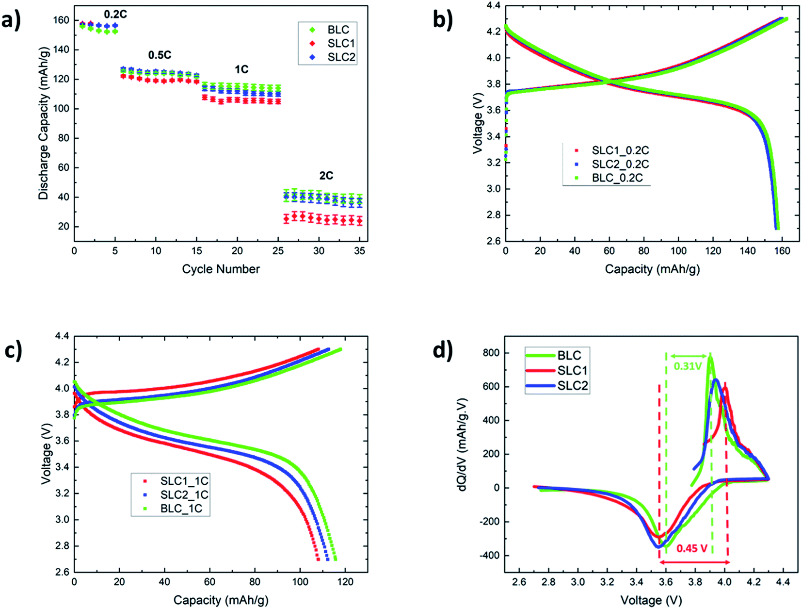 | ||
| Fig. 5 (a) Discharge capacity of the three types of electrodes at different C-rates. Galvanostatic charge–discharge profiles at (b) low (0.2C) and (c) high (1C) C-rates. (d) Incremental capacity against voltage corresponding to (c), where the smoothing of data was performed using a Savitzky–Golay filter. | ||
The polarization of a cell is defined by the voltage difference between charge–discharge curves. The first derivative of capacity with respect to voltage also known as incremental (or differential49) capacity (dQ/dV) was plotted against voltage as shown in Fig. 5(d) to investigate polarization in the cells. The incremental capacity is calculated using the following equation:50
 | (1) |
The voltage difference between the differential peaks in the charge–discharge profiles were taken to calculate the cell polarization21,22 in Fig. 5(c). The differential peaks for SLC1 were not evident at 2C due to a rapid drop in specific capacity. Thus, the polarization was compared at 1C.
The cell polarization decreases in BLC (0.31 V) and SLC2 (0.39 V) as compared to SLC1 (0.45 V). The decrease in cell polarization in BLC and SLC2 could be attributed to the activation overpotential that is required to overcome the charge transfer resistance. Our previous work showed that small particles favor faster effective charge transfer reaction rates due to an increased interfacial surface area.27 This interpretation is found to be consistent with the EIS data presented in section 3.4 and a previous report on designing graded microstructures for next-generation battery electrodes.51 Furthermore, simulation results on the optimization of overpotential show that bi-layer porosity graded design with a higher porosity near the separator leads to a homogeneous overpotential distribution throughout the electrode thickness13 that in turn may further reduce the electrode resistance in BLC compare to SLC2.
EIS studies were performed to investigate and compare the kinetics and transport behavior of the bi-layer electrode with single layer electrodes. Fig. 6(a) shows the Nyquist plots for the electrodes at the end of the cell discharge. A simplified EEC presented in Fig. S4† is used to fit the impedance data.52,53 The EEC consists of Rs representing the cell internal contact resistance, Rct and CPE in parallel reflecting the charge transfer resistance and associated constant phase element, and W indicating the finite length Warburg impedance for solid-state diffusion of Li+ in AM particles. The solid phase diffusivity (Ds) can be estimated by using the following equations:52,53
 | (2) |
 | (3) |
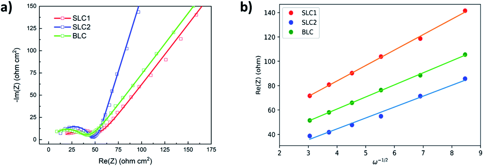 | ||
| Fig. 6 (a) Nyquist plots and (b) linear fitting between Re(Z) and ω−1/2 for the three types of electrodes. The symbols and solid lines represent experimental measurements and the best-fit data respectively. | ||
| Type of cathode | R ct (ohm) | σ (ohm s−1/2) | D s (cm2 s−1) |
|---|---|---|---|
| BLC | 18.33 | 9.90 | 5.63 × 10⁻¹⁴ |
| SLC1 | 25.12 | 12.68 | 3.45 × 10⁻¹⁴ |
| SLC2 | 20.28 | 8.96 | 6.75 × 10⁻¹⁴ |
SLC2 exhibits lower Rct than SLC1. An increase in Li+ flux transfer from the liquid phase to the surface of the solid phase in SLC2 can be correlated with its large interfacial surface area. A further reduction of Rct in BLC can be attributed to the combined grading effect of the particle size and the porosity. The presence of higher porosity in the top layer provides more Li+ access to the depth of the bottom layer, which in turn benefits from the presence of a higher number of reaction sites available for Li+ transfer. The estimated Ds values are consistent with previous reports on diffusivity (∼10−14 cm2 s−1) for NMC532.48,53 SLC2 shows higher Ds than SLC1. As discussed in our previous work, this could be related to the crystal structure, where rigid highly crystalline structures cannot facilitate Li+ diffusion unlike less crystalline or amorphous structures.40,54 This interpretation can be supported by the XRD results presented in the supplementary, where the small particles exhibit a lower degree of crystallinity relative to big particles. The Ds value for BLC falls in between those of SLC1 and SLC2 as its microstructure constitutes layers of both highly crystalline and less crystalline materials.
The cycling performance of all three types of electrodes is shown in Fig. 7(a) including error bars. Three formation cycles were carried out at 0.2C, followed by 100 cycles at 1C. The cycling slope of SLC2 is the steepest one indicating the fastest rate of capacity degradation among the three electrodes. The capacity retention rate for SLC2 was found to be 62.1% at the end of long-term cycling. This capacity degradation can be linked to the growth of a thicker cathode electrolyte interface (CEI) layer due to increased side reactions promoted by an increased interfacial surface area. This CEI layer obstructs Li+ diffusion into the AM particles, which in turn causes a large irreversible capacity. A less steep cycling slope for BLC confirms better cycling performance than SLC2. This can be attributed to the positioning of big particles in the layer next to the separator that may have assisted with mitigating CEI induced capacity decay owing to a decreased interfacial surface area. However, SLC1 shows slightly better cycling performance than BLC, as the capacity retention rates for BLC and SLC1 after 100 cycles were found to be 72.4% and 75.4% respectively. Two possible scenarios may have contributed to the slightly higher capacity decay in BLC: (1) loss of electrical connection caused by the delamination of the interface between the top and bottom layers during long term cycling at a high C-rate and/or (2) the rate of CEI evolution in the bottom layer due to long-term exposure of the electrolyte to the large active interfacial reaction sites may eventually outperform the rate of CEI evolution in the top layer. As a result, this uneven CEI growth may have led to heterogeneous current distribution across the electrode thickness.
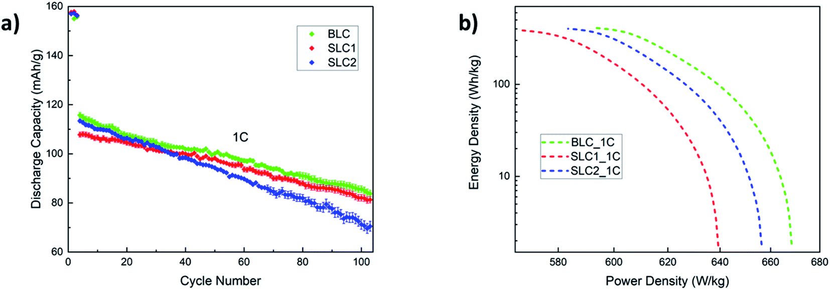 | ||
| Fig. 7 (a) Cycling performance at 1C and (b) Ragone plot for the three types of electrodes based on first discharge capacity at 1C. | ||
Prior literature on microstructural bi-layer graded electrodes has not investigated capacity fade with long-term cycling. The reports have drawn conclusions on the superior cycling performance of graded electrodes over conventional electrodes based solely on initial discharge capacities and short-term cycling (∼50 cycles) at a low C-rate (0.1–0.5C).16,19,23 Previous simulation studies on graded electrodes also predict their performance based on first discharge capacity and without incorporating CEI and mechanical effects.10,14,15,27 Thus, although initially both kinetics and transport within the graded structure can be enhanced via electrode design, long term cycling results (Fig. 7(a)) reveal that such structures may be equally, if not more, susceptible to mechanical and electrochemical degradation as conventional electrodes.
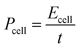
A Ragone plot is depicted in Fig. 7(b) to compare the power and energy density performance of all three electrodes based on first discharge capacity at 1C. Ragone diagrams were first implemented to map the power–energy dependence of various battery systems for EV application.55 In this diagram, the specific energy (Ecell) is plotted against the average specific power (Pcell) with both axes plotted on the logarithmic scale. The following equations are used to calculate Ecell and Pcell:56–58
 | (4) |
 | (5) |
3.4 Effect of drying conditions and fabrication constraints
While a complete investigation of the rheological aspects (i.e., viscosity and density) of the slurry is beyond the scope of this article, a qualitative analysis of the influence of initial slurry drying temperature on the microstructure is performed based on SEM observations. A preferential CB and binder deposition at the electrode surface was observed when the initial drying temperature was set to 60 °C (Fig. S5(a, c and e)†). The crystallographic density of NMC, PVDF and CB is 4.68, 1.78 and 1.95 g cm−3 respectively.32 At low drying temperatures, the larger and heavier NMC particles show considerable gravity-driven sedimentation effects compared to smaller NMC particles and lighter nanometer size (40–100 nm) CB particles. At elevated drying temperature (90 °C), capillary force-driven binder migration to the electrode surface59–61 and crack formation initiated by an increased electrode thickness and solvent evaporation rate59,62,63 were observed (Fig. S5(b, d and f)†). In order to avoid binder migration and crack formation, the wet slurry for the single layer and the bi-layer electrodes was dried between 70 and 80 °C. It should also be noted that a relatively higher initial drying temperature of 80 °C was applied to solidify the electrode/layer composed of big particles in order to stop sedimentation and to minimize the CB and binder deposition at the electrode surface. As the electrode thickness increases, the control of binder migration (leading to poor adhesion to the CC), crack formation and CB percolation becomes more challenging and often results in inconsistent microstructures characterized by unreliable cell performance. This is one of the primary reasons for evaluating ∼200 μm thick electrodes in this experimental work as opposed to the 400 μm thick electrodes studied in our prior modeling study. Additionally, a second deposition step (or multi-layer) including processing of small particles further complicates the synthesis process. Finally, it must be recognized that all the reported novel deposition techniques for fabricating thick electrodes including spray printing, electrostatic spinning, and ice templating are not currently available for large-scale industrial production.4. Conclusions
In this article, the effect of material processing conditions on the morphology of NMC532 particles is studied. The processed materials are used to fabricate a thick bi-layer graded cathode (BLC). The synthesized cathode is prepared by structuring two distinct particle sizes and their corresponding porosities in each layer. The BLC emerges as a promising electrode candidate as it exhibits improved cell performance compared to conventional electrodes during initial cycles. The improvement in cell performance was more evident with increasing C-rate as predicted in previous simulation work. Quantitative studies of polarization and EIS indicate that such improvements can be linked to reduced charge transfer resistance and increased solid-phase diffusivity in the graded electrode. The use of SLC2 electrodes for commercial purposes is inhibited because of their large irreversible capacity loss induced by increased side reactions (CEI formation) related to their large interfacial surface area. The BLC could be a potential electrode candidate for commercial applications. However, noting the extra challenges involved in manufacturing such graded electrode structures via traditional casting methods, it is recommended that their use is best focused on higher C rate applications and that more work is needed to demonstrate the retention of the performance gain over multiple cycles. The authors wish to investigate the influence of slurry rheology on thick electrode microstructures, the electrochemical performance of mixed particles and thin graded electrodes, and the performance of graded electrodes in full cells in future work.Conflicts of interest
There are no conflicts to declare.Acknowledgements
This work is supported by the U.S. Department of Education (ED) and the EPSRC project EP/M009521/1 “Enabling next generation lithium batteries”. The authors thank Dr Xinhua Liu for helpful discussions, Dr Billy Wu for access to battery cyclers, and Dr Alessio Scanziani (International Energy Agency) and Gaetano Garfi for access to the XCT machine.References
- L. Zhou, et al., Recent Developments on and Prospects for Electrode Materials with Hierarchical Structures for Lithium-Ion Batteries, Adv. Energy Mater., 2018, 8(6), 1–23 CrossRef.
- G. E. Blomgren, The Development and Future of Lithium Ion Batteries, J. Electrochem. Soc., 2017, 164(1), A5019–A5025 CrossRef CAS.
- L. W. Ji, et al., Recent developments in nanostructured anode materials for rechargeable lithium-ion batteries, Energy Environ. Sci., 2011, 4(8), 2682–2699 RSC.
- Y. Ding, et al., Automotive Li-Ion Batteries: Current Status and Future Perspectives, Electrochem. Energy Rev., 2019, 2(1), 1–28 CrossRef CAS.
- Y. D. Kuang, et al., Thick Electrode Batteries: Principles, Opportunities, and Challenges, Adv. Energy Mater., 2019, 9(33), 1–19 Search PubMed.
- H. Gao, et al., Revealing the Rate-Limiting Li-Ion Diffusion Pathway in Ultrathick Electrodes for Li-Ion Batteries, J. Phys. Chem. Lett., 2018, 9(17), 5100–5104 CrossRef CAS PubMed.
- S.-T. Myung, et al., Nickel-Rich Layered Cathode Materials for Automotive Lithium-Ion Batteries: Achievements and Perspectives, ACS Energy Lett., 2016, 2(1), 196–223 CrossRef.
- J. Li, et al., Toward Low-Cost, High-Energy Density, and High-Power Density Lithium-Ion Batteries, JOM, 2017, 69(9), 1484–1496 CrossRef CAS.
- V. Ramadesigan, et al., Optimal Porosity Distribution for Minimized Ohmic Drop across a Porous Electrode, J. Electrochem. Soc., 2010, 157(12), A1328–A1334 CrossRef CAS.
- S. Golmon, K. Maute and M. L. Dunn, A design optimization methodology for Li+ batteries, J. Power Sources, 2014, 253, 239–250 CrossRef CAS.
- Y. Dai and V. Srinivasan, On Graded Electrode Porosity as a Design Tool for Improving the Energy Density of Batteries, J. Electrochem. Soc., 2015, 163(3), A406–A416 CrossRef.
- Z. J. Du, et al., Understanding limiting factors in thick electrode performance as applied to high energy density Li-ion batteries, J. Appl. Electrochem., 2017, 47(3), 405–415 CrossRef CAS.
- Y. Qi, et al., Is There a Benefit in Employing Graded Electrodes for Lithium-Ion Batteries?, J. Electrochem. Soc., 2017, 164(13), A3196–A3207 CrossRef CAS.
- E. Hosseinzadeh, J. Marco and P. Jennings, The impact of multi-layered porosity distribution on the performance of a lithium ion battery, Appl. Math. Model., 2018, 61, 107–123 CrossRef.
- S. T. Taleghani, et al., The Effect of Structural Properties of a Two-Layered Electrode on the Li-Ion Battery Polarization, J. Electrochem. Soc., 2019, 166(2), A225–A235 CrossRef CAS.
- C. Huang, et al., A two layer electrode structure for improved Li Ion diffusion and volumetric capacity in Li Ion batteries, Nano Energy, 2017, 31, 377–385 CrossRef CAS.
- C. Huang and P. S. Grant, Coral-like directional porosity lithium ion battery cathodes by ice templating, J. Mater. Chem. A, 2018, 6(30), 14689–14699 RSC.
- C. Huang, et al., Low-tortuosity and graded lithium ion battery cathodes by ice templating, J. Mater. Chem. A, 2019, 7(37), 21421–21431 RSC.
- L. Liu, P. Guan and C. Liu, Experimental and Simulation Investigations of Porosity Graded Cathodes in Mitigating Battery Degradation of High Voltage Lithium-Ion Batteries, J. Electrochem. Soc., 2017, 164(13), A3163–A3173 CrossRef CAS.
- D. Liu, et al., Improvement of Lithium-Ion Battery Performance by Two-Layered Slot–Die Coating Operation, Energy Technol., 2017, 5(8), 1235–1241 CrossRef CAS.
- C. Cheng, et al., Micro-scale graded electrodes for improved dynamic and cycling performance of Li-ion batteries, J. Power Sources, 2019, 413, 59–67 CrossRef CAS.
- C. Cheng, et al., Combining composition graded positive and negative electrodes for higher performance Li-ion batteries, J. Power Sources, 2020, 448, 1–11 Search PubMed.
- K. Song, et al., High performance thick cathodes enabled by gradient porosity, Electrochim. Acta, 2021, 377 Search PubMed.
- W. Wu, X. R. Xiao and X. S. Huang, The effect of battery design parameters on heat generation and utilization in a Li-ion cell, Electrochim. Acta, 2012, 83, 227–240 CrossRef CAS.
- P. Patel and G. J. Nelson, The Influence of Structure on the Electrochemical and Thermal Response of Li-Ion Battery Electrodes, J. Energy Resour. Technol., 2020, 142(5), 1–9 CrossRef.
- H. H. Zheng, et al., A comprehensive understanding of electrode thickness effects on the electrochemical performances of Li-ion battery cathodes, Electrochim. Acta, 2012, 71, 258–265 CrossRef CAS.
- R. Chowdhury, et al., Simulation of bi-layer cathode materials with experimentally validated parameters to improve ion diffusion and discharge capacity, Sustainable Energy Fuels, 2021, 5(4), 1103–1119 RSC.
- M. Stein, et al., Probing the Effect of High Energy Ball Milling on the Structure and Properties of LiNi1/3Mn1/3Co1/3O2 Cathodes for Li-Ion Batteries, J. Electrochem. Energy Convers. Storage, 2016, 13(3), 1–10 CrossRef.
- W. H. Ryu, et al., Electrochemical properties of nanosized Li-rich layered oxide as positive electrode materials for Li-Ion batteries, RSC Adv., 2013, 3(22), 8527–8534 RSC.
- S.-B. Kim, et al., Nanostructure cathode materials prepared by high-energy ball milling method, Mater. Lett., 2011, 65(21–22), 3313–3316 CrossRef CAS.
- C. Busa, M. Belekoukia and M. J. Loveridge, The effects of ambient storage conditions on the structural and electrochemical properties of NMC-811 cathodes for Li-ion batteries, Electrochim. Acta, 2021, 366, 1–10 CrossRef.
- H. Zheng, et al., Calendering effects on the physical and electrochemical properties of Li[Ni1/3Mn1/3Co1/3]O2 cathode, J. Power Sources, 2012, 208, 52–57 CrossRef CAS.
- H. Kang, et al., Geometric and Electrochemical Characteristics of LiNi1/3Mn1/3Co1/3O2 Electrode with Different Calendering Conditions, Electrochim. Acta, 2017, 232, 431–438 CrossRef CAS.
- A. C. Ngandjong, et al., Investigating electrode calendering and its impact on electrochemical performance by means of a new discrete element method model: Towards a digital twin of Li-Ion battery manufacturing, J. Power Sources, 2021, 485, 1–13 CrossRef.
- S. R. Chen, et al., Critical Parameters for Evaluating Coin Cells and Pouch Cells of Rechargeable Li-Metal Batteries, Joule, 2019, 3(4), 1094–1105 CrossRef CAS.
- Z. A. Ghazi, et al., Key Aspects of Lithium Metal Anodes for Lithium Metal Batteries, Small, 2019, 15(32), e1900687 CrossRef PubMed.
- D. Lin, Y. Liu and Y. Cui, Reviving the lithium metal anode for high-energy batteries, Nat. Nanotechnol., 2017, 12(3), 194–206 CrossRef CAS PubMed.
- K. Marker, et al., Evolution of Structure and Lithium Dynamics in LiNi0.8Mn0.1Co0.1O2 (NMC811) Cathodes during Electrochemical Cycling, Chem. Mater., 2019, 31(7), 2545–2554 CrossRef CAS.
- M. Biton, et al., Enhanced Imaging of Lithium Ion Battery Electrode Materials, J. Electrochem. Soc., 2017, 164(1), A6032–A6038 CrossRef CAS.
- J. Wang, et al., Electrochemical properties of 0.6Li[Li1/3Mn2/3]O2–0.4LiNixMnyCo1−x−yO2 cathode materials for lithium-ion batteries, J. Power Sources, 2012, 218, 128–133 CrossRef CAS.
- M. N. He, et al., High Voltage LiNi0.5Mn0.3Co0.2O2/Graphite Cell Cycled at 4.6 V with a FEC/HFDEC-Based Electrolyte, Adv. Energy Mater., 2017, 7(15), 1–9 Search PubMed.
- J. Ahn, et al., Ultrathin ZrO2 on LiNi0.5Mn0.3Co0.2O2 electrode surface via atomic layer deposition for high-voltage operation in lithium-ion batteries, Appl. Surf. Sci., 2019, 484, 701–709 CrossRef CAS.
- L. Zhang, et al., Influence of Charge Cutoff Voltage on the Cycling Behavior of LiNi0.5Mn0.3Co0.2O2 Cathode, J. Electrochem. Soc., 2020, 167(12) DOI:10.1149/1945-7111/abaa17.
- I. Arganda-Carreras, et al., Trainable Weka Segmentation: a machine learning tool for microscopy pixel classification, Bioinformatics, 2017, 33(15), 2424–2426 CrossRef CAS PubMed.
- J. Joos, et al., Representative volume element size for accurate solid oxide fuel cell cathode reconstructions from focused ion beam tomography data, Electrochim. Acta, 2012, 82, 268–276 CrossRef CAS.
- Q. Cai, C. S. Adjiman and N. P. Brandon, Modelling the 3D microstructure and performance of solid oxide fuel cell electrodes: Computational parameters, Electrochim. Acta, 2011, 56(16), 5804–5814 CrossRef CAS.
- L. Almar, et al., Microstructural feature analysis of commercial Li-ion battery cathodes by focused ion beam tomography, J. Power Sources, 2019, 427, 1–14 CrossRef CAS.
- Y. J. Gu, et al., Reduction of the lithium and nickel site substitution in Li1+xNi0.5Co0.2Mn0.3O2 with Li excess as a cathode electrode material for Li-ion batteries, J. Alloys Compd., 2015, 630, 316–322 CrossRef CAS.
- H. Y. Li, et al., Synthesis of Single Crystal LiNi0.6Mn0.2Co0.2O2 with Enhanced Electrochemical Performance for Lithium Ion Batteries, J. Electrochem. Soc., 2018, 165(5), A1038–A1045 CrossRef CAS.
- A. Fly and R. Chen, Rate dependency of incremental capacity analysis (dQ/dV) as a diagnostic tool for lithium-ion batteries, J. Energy Storage, 2020, 29, 1–13 Search PubMed.
- X. Lu, et al., 3D microstructure design of lithium-ion battery electrodes assisted by X-ray nano-computed tomography and modelling, Nat. Commun., 2020, 11(1), 2079 CrossRef CAS PubMed.
- Q. Wang, et al., A facile method of improving the high rate cycling performance of LiNi1/3Co1/3Mn1/3O2 cathode material, J. Alloys Compd., 2016, 686, 267–272 CrossRef CAS.
- K. Sahni, et al., H3PO4 treatment to enhance the electrochemical properties of Li(Ni1/3Mn1/3Co1/3)O2 and Li(Ni0.5Mn0.3Co0.2)O2 cathodes, Electrochim. Acta, 2019, 301, 8–22 CrossRef CAS.
- S. M. Zhang, et al., Li ion diffusivity and electrochemical properties of FePO4 nanoparticles acted directly as cathode materials in lithium ion rechargeable batteries, Electrochim. Acta, 2013, 88, 287–293 CrossRef CAS.
- D. V. Ragone, Review of Battery Systems for Electrically Powered Vehicles, in SAE Technical Paper Series, 1968 Search PubMed.
- M. Doyle and J. Newman, Comparison of Modeling Predictions with Experimental Data from Plastic Lithium Ion Cells, J. Electrochem. Soc., 1996, 143(6), 1890 CrossRef.
- B. Suthar, et al., Effect of Porosity, Thickness and Tortuosity on Capacity Fade of Anode, J. Electrochem. Soc., 2015, 162(9), A1708–A1717 CrossRef CAS.
- W. Mei, et al., The effect of electrode design parameters on battery performance and optimization of electrode thickness based on the electrochemical–thermal coupling model, Sustainable Energy Fuels, 2019, 3(1), 148–165 RSC.
- J. Kumberg, et al., Drying of Lithium-Ion Battery Anodes for Use in High-Energy Cells: Influence of Electrode Thickness on Drying Time, Adhesion, and Crack Formation, Energy Technol., 2019, 7(11), 1–11 CrossRef.
- F. Font, et al., Binder migration during drying of lithium-ion battery electrodes: Modelling and comparison to experiment, J. Power Sources, 2018, 393, 177–185 CrossRef CAS.
- S. Jaiser, et al., Investigation of film solidification and binder migration during drying of Li-Ion battery anodes, J. Power Sources, 2016, 318, 210–219 CrossRef CAS.
- Z. J. Du, et al., Enabling aqueous processing for crack-free thick electrodes, J. Power Sources, 2017, 354, 200–206 CrossRef CAS.
- K. Rollag, et al., Drying Temperature and Capillarity-Driven Crack Formation in Aqueous Processing of Li-Ion Battery Electrodes, ACS Appl. Energy Mater., 2019, 2(6), 4464–4476 CrossRef CAS.
Footnote |
| † Electronic supplementary information (ESI) available. See DOI: 10.1039/d1se01077h |
| This journal is © The Royal Society of Chemistry 2021 |