 Open Access Article
Creative Commons Attribution 3.0 Unported Licence
Nanoflower Ni(OH)2 grown in situ on Ni foam for high-performance supercapacitor electrode materials†
Xuerui
Yi
,
Huapeng
Sun
,
Neil
Robertson
 * and
Caroline
Kirk
*
School of Chemistry and EaStCHEM, University of Edinburgh, King's Buildings, David Brewster Road, Edinburgh, Scotland EH9 3FJ, UK. E-mail: xuerui.yi@ed.ac.uk; h.sun-21@sms.ed.ac.uk; neil.robertson@ed.ac.uk; caroline.kirk@ed.ac.uk
First published on 15th September 2021
Abstract
Supercapacitors hold huge potential to bridge the gap between conventional capacitors and secondary batteries in terms of high-power density, long cycle lifetime and fast charge/discharge rate. Research in the area of transition metal compounds as supercapacitor electrode materials has attracted increasing attention due to the high energy density that can be achieved by these devices compared to electric double-layer capacitors and the long cycle stability when compared to batteries. In this work, we report the one-step synthesis of nickel hydroxide powder and nickel hydroxide directly grown on nickel foam under varying experimental conditions. The formation of flower-like nanostructured α- and β-Ni(OH)2, assembled from nanosheets, was observed and a suggestion for the formation process is proposed. The α-Ni(OH)2 electrode obtained has a high specific surface area of 164 m2 g−1 and a significantly enhanced specific capacitance (2814 F g−1 at 3 A g−1), both higher than previously reported α-Ni(OH)2. Information obtained through characterisation of alpha and beta phases by PXRD, SEM, BET, FTIR and TGA were used in combination with electrochemical studies to rationalise the different electrochemical performance of these 2 phases in terms of their cycle stability and capacitance. This provides guidance for further development and future commercial applications of nickel hydroxide materials for energy storage systems.
1 Introduction
Owing to environmental concerns and a huge market demand in electronic devices, electric vehicles, and smart grids, it is vital to develop high-performance energy storage to efficiently store intermittent and renewable sources, such as wind and solar.1–4 Supercapacitors, also known as electrochemical capacitors, are considered one of the most sustainable and efficient electrochemical energy storage methods/devices, complementing batteries, in term of their high-power density.5,6 According to their charge-storage mechanism, they can be classified into electric double-layer capacitors (EDLCs) and pseudocapacitors (PSCs). EDLCs store charge in an electric double layer formed on the surface of the electrode through physisorption.4,7 As a large surface area can significantly improve the performance of EDLCs, carbon materials with a large specific surface area, such as activated carbon,8 nanotubes9,10 and graphene-based carbons,11 are some of the most widely researched materials for EDLCs. On the other hand, PSCs store charge mainly by Faradaic electron transfer processes involving reversible redox reactions at or near the surface of the electrode material.12,13 Various redox-active materials have been studied in PSCs to enhance their specific capacitance, e.g., RuO2,14 MnO2,12 Co3O4,15 Ni(OH)2 (ref. 16–19) and polyaniline.20 Among these materials, nickel hydroxide is one of the most promising and attractive pseudocapacitive materials.16,17,21–24 This is due to its high specific capacitance, low cost when compared to precious metal compounds, and good stability.25–27 However, commercial nickel hydroxide has a small specific surface area and poor conductivity, which hinders its further development in practical applications. It is therefore vital to develop synthesis of nickel hydroxide which has high specific surface area and may exhibit better electrochemical performance.Nickel hydroxide exists as two types (sometimes termed polymorphs), known as α-Ni(OH)2 and β-Ni(OH)2 and both structures consist of layers of edge-sharing Ni(OH)6 octahedra. The main difference between these two types is the distance between the Ni(OH)6 octahedral layers and whether any ions/water molecules are inserted/present between these layers25 (Fig. S1†). The interlayer distance of β-Ni(OH)2 is about 0.46 nm and there is no intercalation of water molecules between the octahedral layers.24,28,29 The interlayer distance of α-Ni(OH)2 is around 0.8 nm, with intercalation of water molecules and possibly oxyanions between the layers.24,28,29 The divalent α-Ni(OH)2 and β-Ni(OH)2 polymorphs are oxidized to the trivalent γ-and β-NiOOH forms respectively during the charging process. This forms two reversible couples α-Ni(OH)2/γ-NiOOH and β-Ni(OH)2/β-NiOOH. Based on the different unit cell volumes of these four compounds, the electrodes experience different volume changes during the charge and discharge processes leading to different electrochemical performance and cycle stabilities.17,21,30–32 It is proposed that the intercalated ions in α-Ni(OH)2, such as water molecules, play an important role during the discharge process of Nin+OOH, as they can facilitate the mobility of protons and quickly replenish protons at the reaction interface.25,33–35 Additionally, α-Ni(OH)2/γ-NiOOH generally shows superior capacity compared with the β-couple. According to previous work,28,36,37 the oxidised forms, with the proposed formula, NiOOH, are in reality stated to have different average oxidation states of Ni. For instance, γ-NiOOH is stated to contain some Ni with an oxidation state Ni4+ leading to an average oxidation state of 3.3 to 3.7, i.e.
| Nin+OOH + H+ + (n − 2)e− = Ni(OH)2 (3 < n < 4) |
These differences for α-Ni(OH)2 and β-Ni(OH)2 will affect the electrochemical performance of α-Ni(OH)2 and β-Ni(OH)2 electrodes.17,30,38
Wang et al.23 studied α-Ni(OH)2 with a nanowire structure and reported a specific capacitance of 833 F g−1 at a constant current of 5 mA cm−1. To improve the electrochemical performance of α-Ni(OH)2, Zheng et al. subsequently prepared Zn-doped α-Ni(OH)2 with flower-like nanostructure by electrodeposition. The specific capacitance of their work reached 860 F g−1 at a current density of 10 mA cm−1.22 Aghazadeh et al. also used electrochemical preparation to grow α-Ni(OH)2 nanowires on a steel cathode. The electrode has a specific surface area of 145 m2 g−1 and capacitance of 2301 F g−1 at 1 A g−1.24 According to Yan et al., α-Ni(OH)2, prepared by microwave heating with graphene, gave a specific capacitance of 1735 F g−1 at 1 mV s−1.16 Compared with α-Ni(OH)2, much research focuses on β-Ni(OH)2 because this phase is more stable and easier to synthesise. For example, Yuksel et al.39 synthesised silver nanowire network core and β-Ni(OH)2 shell composites of one-dimensional coaxial architecture for supercapacitors exhibiting a specific capacitance of 1165 F g−1 at 3 A g−1. Wei et al. reported a hierarchical three-dimensional interspersed flower-like β-Ni(OH)2 with carbon tubes.32 The electrode shows a specific capacitance of 2225 F g−1 at 0.5 A g−1. However, there are few studies on the preparation of α-Ni(OH)2 with high specific surface area and capacitance in supercapacitors. Therefore, investigation into preparation of alpha using a simple, one-step method with no additives is required, to determine whether improvements in its electrochemical performance can be made.
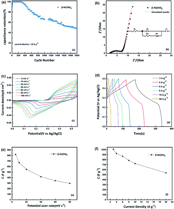
In this work, we designed a one-step approach to synthesise the two different types of nickel hydroxide grown in situ onto a Ni foam substrate via a hydrothermal process and studied the formation of flower-like nanostructures. The phase identification and electrochemical performance of α-Ni(OH)2 and β-Ni(OH)2 were investigated and evaluated. Compared with the aforesaid literature, the as-fabricated α-Ni(OH)2 nanosheets in this study were intertwined as 3D flower-like structures exhibiting a relatively high specific surface area of 164 m2 g−1. This novel 3D structure of α-Ni(OH)2 can provide rich electroactive sites and increase contact area with the electrolyte, improving the utilization efficiency of the active material. The α-Ni(OH)2 nanosheets, in situ deposited onto Ni foam substrate, have an open structure shortening diffusion paths for electrons and ions thus enhancing the electrochemical reaction to achieve a high specific capacitance (2814 F g−1 at 3 A g−1). Additionally, the Ni foam covered nickel hydroxide nanosheets can be used as electrodes without any other binders or additives to the benefit of their conductivity. The capacitance retention of the α-Ni(OH)2 electrode is 57% after 2000 continuous charge–discharge cycles at a high current density of 10 A g−1 in alkaline electrolyte. To compare, the β-Ni(OH)2 with a flower-like structure was also prepared by a hydrothermal process using NH4F as an additive. The β-Ni(OH)2 electrode has a specific capacitance of 1011 F g−1 at 3 A g−1 and the capacitance retention of the β-Ni(OH)2 electrode is 47.6% at 10 A g−1 for 2000 cycles. The foreign ions incorporated into the α-Ni(OH)2 structure and the different volume changes for the reversible couples α-Ni(OH)2/γ-NiOOH and β-Ni(OH)2/β-NiOOH both result in different electrochemical performance.
2 Experimental section
2.1 Synthesis of nickel hydroxide
All chemicals were commercially purchased (Sigma Aldrich, Acros Organics) and were used without further purification. Ni foam (from Li Yuan Company) with a size of 2 cm × 1 cm was pre-treated successively with acetone, 1 M HCl solution, deionized water (DI water) and absolute ethanol, each for 25 min to ensure a clean surface. A hydrothermal method was used for the one-step synthesis of nickel hydroxide powder and nickel hydroxide directly grown on nickel foam. Nickel nitrate (Ni(NO3)2·6H2O, 0.8724 g, 3 mmol) and urea (0.360 g, 6 mmol) were dissolved in 60 ml DI water by ultra-sonication for 30 min. The mixed solution, along with the pre-treated nickel foam (2 cm × 1 cm), were transferred into a 100 ml Teflon-lined autoclave. The autoclave was heated in an oven at 200 °C for 12 h to allow the growth of nickel hydroxide nanosheets on the nickel foam. After the reaction, the nickel foam substrate covered with nickel hydroxide was washed with DI water and absolute ethanol several times. It was dried at 60 °C overnight to remove the absorbed solvent. The nickel hydroxide grown on the nickel foam can be directly used as the working electrode. In order to investigate the electrochemical performance of nickel hydroxide materials prepared under different experimental conditions, different starting reagents (Ni(NO3)2·6H2O, NiCl·6H2O), ratios of nickel salts to urea, additives (NH4F), times and temperatures were used (details are shown in Table S1†).2.2 Materials characterization
Powder X-ray diffraction (PXRD) data were collected using a Bruker (D2 PHASER) in reflection geometry, with CuKα radiation (λ = 1.5418 Å), a scanning speed of 0.2 steps per second and step size of 0.0365° 2θ over the two-theta range 5 to 60/65° 2θ. Scanning Electron Microscopy (SEM) images were collected using a ZEISS SIGMA Field Emission SEM, operated in SE2 mode with 10 kV accelerating voltage. Nitrogen adsorption was used to determine the specific surface area and pore size distribution of the materials. The samples were placed in a vacuum of 2.7 torr at 100 °C for 14 hours before testing. Then, the samples were cooled to liquid nitrogen temperature and tested using a Micrometrics ASAP 2020 instrument. Thermogravimetric analysis (TGA) was used to measure weight loss as a function of temperature, to monitor any decomposition/dehydration processes and phase changes. Data were collected using a Netzsch STA 449 F1 thermal analyser, from room temperature to 600 °C with a ramp rate of 5 °C min−1 under a N2 flow. Fourier Transform Infrared spectroscopy (FTIR) was used to investigate the presence of anions, which may be incorporated in interlayers of Ni(OH)2. An attenuated total reflection attachment was used, and data were collected over the range of 500 to 4000 cm−1 using a PerkinElmer FT-IR spectrometer.2.3 Electrochemical measurements
Electrodes were investigated in three-electrode configurations with 1 M KOH solution. Platinum foil and Ag/AgCl electrodes (3 M KCl) were used as counter and reference electrodes, respectively. Cyclic voltammetry (CV), galvanostatic charge/discharge measurements and electrochemical impedance spectroscopy (EIS) in this work were carried out using an Autolab PGSTAT30 with General purpose electrochemical system (GPES) and frequency response analyser software.The specific capacitance and areal capacitance of the working electrode were calculated from galvanostatic charge–discharge curves as follows:
| Cs = I × Δt/(ΔV × m) | (1) |
The specific capacitance can also be estimated by integration of the CV curves applying the equation:
 | (2) |
3 Result and discussion
3.1 Characterization of α-Ni(OH)2 and β-Ni(OH)2
Nickel hydroxide electrode materials prepared under different synthetic conditions (details are shown in Table S1†) were investigated. All samples were characterized by PXRD to identify the polymorph(s) of nickel hydroxide present and their electrochemical performance was then measured using Cyclic Voltammetry (CV) and galvanostatic charge–discharge, as shown in Fig. S2 and S3.† Following this, the samples of the α-Ni(OH)2 and β-Ni(OH)2 of the highest specific capacitance among all samples (abbreviated as alpha-2 and beta-3) were selected for further analysis, in terms of morphology and electrochemical performance. The powder X-ray diffraction data of alpha-2 and beta-3 (Fig. 1(a)) are in good agreement with the standard PXRD data of α-Ni(OH)2 (ICDD-38-715) and β-Ni(OH)2 (ICDD-14-117). The main observed two theta positions and their assigned hkl indices for these two samples are shown in Table S2.† It is noted that the observed (003) and (006) reflections of α-Ni(OH)2 in this work are shifted to higher two-theta values than the standard pattern ICDD-38-715 (Fig. 1(a)). This indicates a decrease in the c-unit cell parameter of this sample compared to that published in ICDD 38-715.40 The lattice parameters of alpha-2 in this work were refined using a least squares procedure in the rhombohedral crystal system, as a = 3.098(5) Å, c = 21.60(6) Å. There is a significant decrease in comparison to the ICDD data, a = 3.08 Å, c = 23.41 Å. This can be attributed to different types and/or amounts of planar polyanions or water molecules between the Ni(OH)6 octahedral sheets, which influence the c parameter and for our material we observe a contraction in c. A similar shift for α-Ni(OH)2 was also published for hydrothermally synthesized α-Ni(OH)2 hollow spheres,41 a microwave synthesis for α-Ni(OH)2,16 and a sonochemical synthesis α-Ni(OH)2 nanoflakes.42 An asymmetry and broadening of the reflections over the two-theta range 30–40°, where the 101 and 012 reflections are observed, suggest the formation of the α-Ni(OH)2; whereby, the octahedral sheets become very disordered along the c axis. This hydrotalcite-like random layered structure of α-Ni(OH)2 is also known as a turbostratic phase.25 The crystal structure of α-Ni(OH)2 and β-Ni(OH)2 are shown in Fig. S1.†Fig. 1(b) shows the PXRD data collected on the alpha and beta samples directly grown on nickel foam. The observed reflections match well with the standard ICDD pattern for α-Ni(OH)2 and β-Ni(OH)2. Intense reflections associated with Ni, from the nickel foam substrate, are also observed (ICDD 4-850). This means that the as-prepared Ni(OH)2–Ni foam can be directly used as a supercapacitor electrode without any additional binder or conductive agent. In general, the traditional slurry approach to fabricate Ni(OH)2 electrodes, involves mixing the active material, binder and conduction material thoroughly to form a slurry and then coating it onto a current collector. This process is more complicated and expensive. In contrast, the approach in this work enables the active material, Ni(OH)2, to adhere on the current collector (Ni foam), with no additional binder that would reduce the conductivity of electrodes.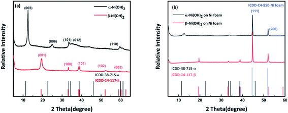 | ||
| Fig. 1 (a) PXRD patterns of nickel hydroxide powder compared to standard patterns from ICDD (b) PXRD patterns of nickel hydroxide grown on nickel foam compared to standard patterns from ICDD. | ||
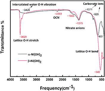
Infrared spectroscopy was used to further characterise the two samples, to investigate the presence of anions. For α-Ni(OH)2 (black line in Fig. 2), the broad and weak peak at 3426 cm−1 is attributed to the O–H vibration of nickel hydroxide and intercalated water in the interlayer spacing of the turbostratic structure of α-Ni(OH)2.16,17 The peaks at 829 cm−1 and 1071 cm−1 are likely due to absorption of CO2 during synthesis, released from the urea hydrolysis. The peak at 651 cm−1 is assigned to the lattice O–H bend.25 For β-Ni(OH)2 (red line in Fig. 2), the peaks at 3629 cm−1 and 542 cm−1 are associated with the lattice O–H stretch and bend, respectively.25 The weak bands around 2203 cm−1 can be assigned to the typical vibration of the triple bond between C and N in the OCN− ions, which can be produced by the hydrolysis of urea.43 The peaks at 1375 cm−1 suggest the presence of interlayer nitrate anions.43 Overall, the FTIR is suggesting the presence of anions and water molecules within the alpha structure. For beta, it may have a presence of a trace amount of nickel hydroxy nitrate-type phases, not in quantities detectable by PXRD techniques, but observable by FTIR.44
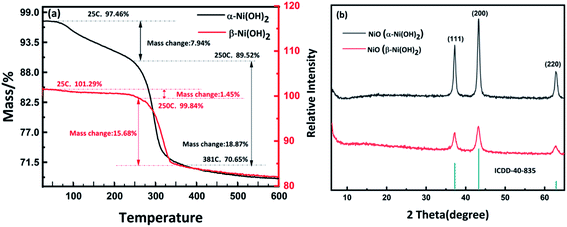
As mentioned above, different forms of nickel hydroxide may include different types of water such as surface water, incorporated water and structural or intercalated water.25 According to the review by D. S. Hall et al., the number of water molecules will significantly influence the electrochemical performance of nickel hydroxide.25 Thermogravimetric analysis (TGA) was used to measure the number of water molecules in the alpha-2 and beta-3 nickel hydroxide samples and determine the dehydration pathways (Fig. 3). The TGA trace for α-Ni(OH)2 shows that surface adsorbed water can be removed over the temperature range from 25 °C to 250 °C, with an observed mass change of 7.94 wt%. For beta-3, the weight loss is 1.45 wt% between 25 °C and 250 °C, which indicates the mass of surface water in β-Ni(OH)2 is significantly lower than α-Ni(OH)2. The TGA results show that alpha-2 nickel hydroxide has absorbed or intercalated water molecules in agreement with the results of FTIR as discussed above. Above 250 °C, both β-Ni(OH)2 and α-Ni(OH)2 start to decompose to NiO. The residues after the TGA measurements β-Ni(OH)2 and α-Ni(OH)2 were analysed by PXRD which further confirmed that they transformed to NiO, as illustrated in Fig. 3(b).
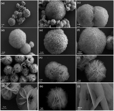
Scanning electron microscopy (SEM) was used to investigate the morphology and microstructure of the selected as-prepared samples, which had shown promising results from the electrochemical analysis. Fig. S4(e),† shows a digital photograph of Ni foam before and after the hydrothermal treatment to form Ni(OH)2 and there is a significant colour change between the two from the grey metallic lustre to green, indicating the formation of a new substance on the Ni foam surface as confirmed by PXRD (Fig. 1). Fig. 4(a–f) show images from the sample of alpha-2 which was confirmed to be α-Ni(OH)2 by PXRD (Fig. 1). The size of the spheres varies from approximately 800 nm to 8 μm. As shown in the high-resolution image of Fig. 4(e), flower-like spheres are densely composed of agglomerated nanometre-scale two-dimensional sheets. It is noted that these flower-like spheres, agglomerations of thin and thick nanosheets, lead to an open and porous three-dimensional structure. This structure can provide a large surface area for electrolyte access and diffusion of ions. Fig. 4(g–l) shows the sample of beta-3 which is confirmed to be β-Ni(OH)2 by PXRD. Compared with α-Ni(OH)2, the size of the aggregated units in this sample is more uniform with a diameter of around 4 μm. As shown in the high-resolution image of Fig. 4(j–l), these flower-like microspheres are also constructed from nanosheets to form an open and three-dimensional structure. This might be attributed to the impact of ammonium fluoride (NH4F) in the morphological control of samples.45 Shown in Fig. S4(a and b, c and d)† are α-Ni(OH)2 and β-Ni(OH)2 directly grown on the Ni foam respectively. Regular nanosheets are grown vertically onto the Ni foam grid at high density (Fig. S4(b)†), connecting with each other and covering the whole surface of the Ni foam. The arrangement of nanosheets on the Ni foam effectively prevents further agglomeration of particles and facilitates the penetration of electrolyte.
Based on SEM results, nitrogen adsorption and desorption measurements were also used to investigate the surface area and pore size distribution of alpha-2 and beta-3 as shown in Fig. 5. The adsorption–desorption isotherm of alpha-2 shows a hysteresis loop in the range of ca. 0.5–1.0 P/P0, further indicating the existence of a richer mesoporous structure than beta-3. Based on the Brunauer–Emmett–Teller (BET) analysis, the alpha-2 has a relatively high specific surface area of 164 m2 g−1, higher than previously reported for α-Ni(OH)2.31,41,46 This high specific surface area is consistent with porous microstructures assembled from nanosheets, as shown by the SEM results. The Barrett–Joyner–Halenda (BJH) model was used to calculate the pore size distribution of α-Ni(OH)2 and β-Ni(OH)2. From Fig. 5(b), the pore size of alpha-2 is around 14 nm which is in the range of 2–50 nm, considered as an ideal structure for electrode materials.13 The high specific surface area and an appropriate porous structure of alpha-2 will effectively increase the contact area between the electrolyte and the active material and therefore shorten the migration path of the ions leading to good rate capability.
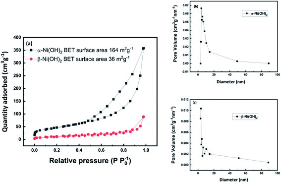 | ||
| Fig. 5 (a) Nitrogen adsorption–desorption isotherm of α-Ni(OH)2 and β-Ni(OH)2 (b) pore size distribution of α-Ni(OH)2 (c) pore size distribution of β-Ni(OH)2. | ||
Based on the above discussion, a possible process for the formation of nickel hydroxide nanoflowers is proposed, as shown in Fig. 6. In this work, when the reaction was heated to 100 °C, CO2 and NH3 gas is released from the hydrolysis of urea which can generate gas bubble templates.30,47 The basic conditions also generate OH− and CO32−. According to literature48 from Tong et al., the by-product OCN− can be generated by the hydrolysis of urea. The existence of carbonate ions and OCN− in the products was confirmed by the FTIR results above (Fig. 2).
According to a classical nucleation and growth process,49–52 the flower-like α-Ni(OH)2 growth can proceed in three stages.22,30,32 In this first stage (step1 in Fig. 6), Ni2+ reacts with OH− anions, slowly released from hydrolysis of urea, to form Ni(OH)2 monomers, which coalesce to form nanoparticles that aggregate around gas bubbles and grow into the initial nano-floccules, which are thermodynamically unstable due to the high surface energy. In the second stage (step 2 in Fig. 6), nano-floccule chains can be formed due to dipolar interactions between nanoparticles, which will allow the subsequent adsorption of newly formed nuclei and the growth of primary particles. In the final stage (steps 3–4 in Fig. 6), the Ni(OH)2 primary particles continue to aggregate and start to crystallize and grow along the c-axis gradually leading to the formation of nanosheets. Owing to the large surface area fraction and high surface energy, the nanosheets can aggregate forming flower-like spheres.
For the β-Ni(OH)2 in this work, the growth process is more complicated than α-Ni(OH)2 due to the addition of ammonium fluoride in the system. Nickel ions can react with F− to form NiFx(x−2)− coordination complexes in the hydrothermal system.45,53,54 Nucleation and growth rates of products may be affected by different dissociation constants (Kd).55,56,57 In this case, coordination of Ni2+ with F− leads to slower Ni2+ release than found in the preparation of α-Ni(OH)2, with no additives in the system. Meanwhile, NH4+ ions from the NH4F additive will reduce the amount of OH− in the reaction system based on the reversible reaction forming NH3 and H2O. Thus, the reaction rate to form β-Ni(OH)2 is slower than α-Ni(OH)2 in the hydrothermal process. Zhu et al. revealed that the slow reaction rate of Ni2+ with OH−, benefits the separation of nucleation and growth processes resulting in outstanding crystallinity.58 This is consistent with highly crystalline β-Ni(OH)2 forming with the additive NH4F, compared to the turbostratic structure of α-Ni(OH)2, as confirmed by the XRD results (Fig. S2†).
3.2 Electrochemical performance of α-Ni(OH)2 and β-Ni(OH)2
A three-electrode configuration in 1.0 M KOH aqueous solution was first used to evaluate the electrochemical performance of the as-prepared α-Ni(OH)2 electrode (alpha-2) and β-Ni(OH)2 electrode (beta-3) as a supercapacitor electrodes. Fig. 7(c) exhibits typical CV curves of the alpha-2 electrode at different scan rates. The oxidation peaks and reduction peaks are observed at around 0.40 V and 0.15 V respectively. The corresponding reversible reaction is:16,38| Ni(OH)2 + OH− ⇌ NiOOH + H2O + e− | (3) |
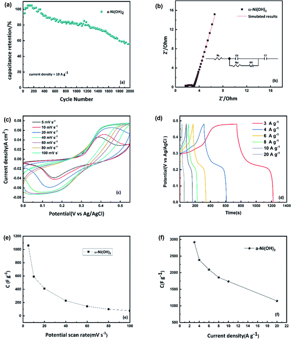
As the scan rate increases from 5 mV s−1 to 100 mV s−1, the oxidation peak moves to a more positive potential and the reduction peak moves to a more negative potential which indicates the electrochemical irreversibility of the active material. The specific capacitance of the alpha-2 electrode, calculated from the integral area of the CV results, plotted in Fig. 7(e). Fig. 7(d), shows the charge–discharge curves of the alpha-2 electrode at different current densities. All samples exhibit a stable discharge plateau in the voltage range 0.2–0.3 V corresponding to the reduction process of the active material, showing that the energy storage of Ni(OH)2 is a type of pseudocapacitive behaviour dominated by the faradaic process. The specific capacitance of alpha-2 electrode is calculated from charge–discharge curves, plotted in Fig. 7(f). It is noted that the specific capacitance of 2814 F g−1 at 3 A g−1, is higher than many transition metal oxides and higher than previous reports of Ni(OH)2.16,17,21–24 The remarkable electrochemical performance might be attributed to its unique nanoflower structure shown in the SEM results. It suggests that the accumulated nanosheets, form nanoflower particles with a high surface area which is beneficial to the contact of the electrode/electrolyte interface and increases the active sites for electrochemical reactions. As shown in Fig. 7(f), the specific capacitance decreases from 2814 F g−1 to 1096 F g−1 with increasing current density. It is noted that the alpha-2 electrode retains 1096 F g−1 even at a high current density of 20 A g−1. This good rate capability can be attributed to intercalated water molecules in the large interlayer spacing. The water molecules in the larger spacing of α-Ni(OH)2 enable quick replenishment of protons at the reaction interface showing better rate performance.28 According to literature from Oshitani M. et al., the theoretical bulk density of alpha phase is 2.82 g cm−3 due to its large interlayer spacing, which is lower than 3.97 g cm−3 of beta phase.59 To evaluate the overall electrochemical performance, the specific capacitance and capacity are calculated shown in Table S3.† With the increase of current densities, the capacitance of the α-Ni(OH)2 electrode decreases. This is typical behaviour and may be attributed to some active chemical sites becoming inaccessible for the redox reaction due to limitations of electrolyte ion diffusion and electron transport at shorter timescales. The cycle stability is an important parameter to evaluate for the potential practical performance of electrode materials. From Fig. 7(a), it is observed that there is an increase of capacitance after nearly 100 cycles attributed to better penetration of electrolyte into active electrode material. The capacitance retention ratio of the α-2 electrode is 57% after 2000 continuous charge–discharge cycles at 10 A g−1.
The electrochemical performance of the beta-3 electrode is given in Fig. 8(a–f). The CV curves of the beta-3 electrode were measured at different scan rates from 5 to 100 mV s−1 (Fig. 8(c)). It is observed that the pair of redox peaks are asymmetric indicating poorer reversibility of beta-3 than alpha-2. However, the shapes of the CV curves with an increase of scan rate, does not obviously change, suggesting good electron conductivity of beta-3. The calculated capacitance values of beta-3 from CV and charge–discharge results are plotted in Fig. 8(e and f). Based on calculated results, the alpha-2 electrode has higher capacitance than the beta-3 electrode. As mentioned before, this might be attributed to the higher number of exchange electrons between α-Ni(OH)2 and γ-NiOOH.28,36,37 Additionally, the better electrochemical performance of α-Ni(OH)2 also might be due to the interaction of the structurally incorporated water in the lattice of α-Ni(OH)2 which leads to this large difference of capacitance.28 According to Lukovtsev et al.60 the Ni(OH)2 electrode is first reduced at the surface layer during the discharge process and then a proton can diffuse from the surface into the electrode as the reaction continues while accompanied by electron transfer. The rate of the entire reaction is determined by proton diffusion. In the α-Ni(OH)2/γ-NiOOH system, the structural water can facilitate diffusion of the proton which can be beneficial to the transmission of electrons and accelerate the speed of the entire electrochemical reaction. Fig. 8(a) shows the cyclic performance of the beta-3 electrode. The capacitance retention of the beta-3 electrode is 47% at 10 A g−1 for 2000 cycles. However, it is noted that the beta-3 electrode exhibits nearly 100% specific capacitance retention up to around 400 cycles. The reason for the different cycle performances of the two nickel hydroxides might relate to the different phases formed on oxidation. The α-Ni(OH)2 and β-Ni(OH)2 are oxidised to γ-NiOOH and β-NiOOH in the separate charging process. This means that the change in α- and β-Ni(OH)2 electrode volume is also different. The α-Ni(OH)2/γ-NiOOH couple experiences around 47% volume change, which is larger than β-Ni(OH)2/β-NiOOH couple (5.6% volume change).25,40,61
Nyquist plots of nickel hydroxide in the frequency range of 0.02–105 Hz are shown in Fig. 7(b) and Fig. 8(b). The equivalent circuit used to fit the impedance curves is also presented (insets in Fig. 7(b) and Fig. 8(b)). The Nyquist plot consists of an offset along the real axis due to the effective series resistance, a semicircle in the high-frequency region, and a straight line in the low-frequency region. The equivalent circuit used to model these features is shown as an inset. Rs of α-Ni(OH)2 and β-Ni(OH)2 are 1.78 Ω and 2.35 Ω respectively, which indicates higher conductivity of α-Ni(OH)2 than β-Ni(OH)2. The diameters of the respective semicircles gave Rct of α-Ni(OH)2 as 0.94 Ω which is smaller than β-Ni(OH)2 (3.8 Ω), indicating faster charge transport to form the double layer of α-Ni(OH)2. The straight line at the low-frequency region describes the diffusion resistance of ions from the electrolyte solution to the electrode interface. Both the straight lines of α-Ni(OH)2 and β-Ni(OH)2 are inclined at an angle of more than 45 degrees suggesting that the flower-structure of nickel hydroxide can benefit electrolyte ions transport and more ideal capacitor behaviour.
Fig. 9 shows the PXRD data collected on the sample of alpha-2 and beta-3 before and after electrochemical testing. After the electrochemical cycling, the peak widths of the beta-3 are observed to broaden, suggesting a slight degradation in the crystallinity of the phase. No other reflections were observed to indicate any degradation of the phase. For the sample of alpha-2, analysis of these data shows that the sample has degraded becoming mostly amorphous, with only one very broad and weak reflection at ∼11 degree observed, which may be associated with α-Ni(OH)2. Fig. S5(a–d)† shows the SEM images from the sample of alpha-2 after electrochemical testing. As shown in Fig. S5(b),† the hollow structure of some flower-like spheres has collapsed, which might relate the degradation shown in the PXRD pattern.
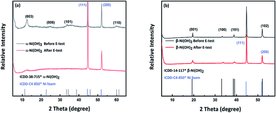 | ||
| Fig. 9 (a) PXRD pattern of β-Ni(OH)2 on Ni foam before and after electrochemical measurements. (b) PXRD pattern of α-Ni(OH)2 on Ni foam before and after electrochemical measurements. | ||
4 Conclusions
In this work, we have designed and prepared flower-like nanostructured α-Ni(OH)2 and β-Ni(OH)2 materials by a simple hydrothermal method. The possible process for forming the nano-flower structured material was discussed. The additive NH4F appears to play a role in determining the phase of nickel hydroxide obtained, although further exploration of this point is needed. The effect of the different structures and morphologies of α-Ni(OH)2 and β-Ni(OH)2 on the performance and mechanism of the electrodes during charge/discharge were investigated and evaluated. Using nickel nitrate hexahydrate as a nickel source and urea as a base, when reacted for 12 hours at 200 °C, the resulting α-Ni(OH)2 has a high specific surface area of 164 m2 g−1. The nanoflower-like microstructure and high specific surface area of our α-Ni(OH)2 material, motived detailed study as a supercapacitor electrode material. To enable this, we improved the synthesis method for in situ formation of nanosheets of nickel hydroxide on Ni foam, which can be directly used as an electrode. From the above results, the alpha-2 electrode has good electron transport and the open nanosheet microstructure improves the penetration of electrolyte into the electrode material and therefore exhibits a significantly enhanced specific capacitance of 2814 F g−1 at 3 A g−1, which is higher than previously reported for α-Ni(OH)2 electrodes.16,17,21–24Conflicts of interest
The authors state there are no conflicts to declare.Acknowledgements
The authors would like to thank Dr Nicola Cayzer from the School Geosciences University of Edinburgh for guidance on SEM characterization. The authors would like to thank Dr Rebecca Rae for her help in performing TGA and IR measurements.Notes and references
- P. Simon, Y. Gogotsi and B. Dunn, Where Do Batteries End and Supercapacitors Begin?, Science, 2014, 343, 1210–1211 CrossRef CAS PubMed
.
- Y. Gogotsi and R. M. Penner, Energy Storage in Nanomaterials – Capacitive, Pseudocapacitive, or Battery-like?, ACS Nano, 2018, 12, 2081–2083 CrossRef CAS PubMed
.
- Y. Shao, M. F. El-Kady, J. Sun, Y. Li, Q. Zhang, M. Zhu, H. Wang, B. Dunn and R. B. Kaner, Design and Mechanisms of Asymmetric Supercapacitors, Chem. Rev., 2018, 118, 9233–9280 CrossRef CAS PubMed
.
- X. Li and B. Wei, Supercapacitors based on nanostructured carbon, Nano Energy, 2013, 2, 159–173 CrossRef CAS
.
- W. Zuo, R. Li, C. Zhou, Y. Li, J. Xia and J. Liu, Battery-Supercapacitor Hybrid Devices: Recent Progress and Future Prospects, Adv. Sci., 2017, 4, 1600539 CrossRef PubMed
.
- J. Xie, P. Yang, Y. Wang, T. Qi, Y. Lei and C. M. Li, Puzzles and confusions in supercapacitor and battery: Theory and solutions, J. Power Sources, 2018, 401, 213–223 CrossRef CAS
.
- L. L. Zhang and X. S. Zhao, Carbon-based materials as supercapacitor electrodes, Chem. Soc. Rev., 2009, 38, 2520 RSC
.
- J. Gamby, P. L. Taberna, P. Simon, J. F. Fauvarque and M. Chesneau, Studies and characterisations of various activated carbons used for carbon/carbon supercapacitors, J. Power Sources, 2001, 101, 109–116 CrossRef CAS
.
- A. Izadi-Najafabadi, T. Yamada, D. N. Futaba, M. Yudasaka, H. Takagi, H. Hatori, S. Iijima and K. Hata, High-Power Supercapacitor Electrodes from Single-Walled Carbon Nanohorn/Nanotube Composite, ACS Nano, 2011, 5, 811–819 CrossRef CAS PubMed
.
- L.-C. Qin, X. Zhao, K. Hirahara, Y. Miyamoto, Y. Ando and S. Iijima, The smallest carbon nanotube, Nature, 2000, 408, 50 CrossRef CAS PubMed
.
- Y. Wang, Z. Shi, Y. Huang, Y. Ma, C. Wang, M. Chen and Y. Chen, Supercapacitor Devices Based on Graphene Materials, J. Phys. Chem. C, 2009, 113, 13103–13107 CrossRef CAS
.
- J. Sun, C. Wu, X. Sun, H. Hu, C. Zhi, L. Hou and C. Yuan, Recent progresses in high-energy-density all pseudocapacitive-electrode-materials-based asymmetric supercapacitors, J. Mater. Chem. A, 2017, 5, 9443–9464 RSC
.
- H. Sun, G. Yang, J. Chen, C. Kirk and N. Robertson, Facile synthesis of BiSI and Bi13S18I2 as stable electrode materials for supercapacitor applications, J. Mater. Chem. C, 2020, 8, 13253–13262 RSC
.
- C.-C. Hu, K.-H. Chang, M.-C. Lin and Y.-T. Wu, Design and Tailoring of the Nanotubular Arrayed Architecture of Hydrous RuO2 for Next Generation Supercapacitors, Nano Lett., 2006, 6, 6 Search PubMed
.
- S. K. Meher and G. R. Rao, Ultralayered Co3O4 for High-Performance Supercapacitor Applications, J. Phys. Chem. C, 2011, 31, 15646–15654 CrossRef
.
- J. Yan, Z. Fan, W. Sun, G. Ning, T. Wei, Q. Zhang, R. Zhang, L. Zhi and F. Wei, Advanced Asymmetric Supercapacitors Based on Ni(OH)2/Graphene and Porous Graphene Electrodes with High Energy Density, Adv. Funct. Mater., 2012, 10, 2632–2641 CrossRef
.
- J. W. Lee, T. Ahn, D. Soundararajan, J. M. Ko and J.-D. Kim, Non-aqueous approach to the preparation of reduced graphene oxide/α-Ni(OH)2 hybrid composites and their high capacitance behavior, Chem. Commun., 2011, 47, 6305 RSC
.
- G. S. Gund, D. P. Dubal, S. B. Jambure, S. S. Shinde and C. D. Lokhande, Temperature influence on morphological progress of Ni(OH)2 thin films and its subsequent effect on electrochemical supercapacitive properties, J. Mater. Chem. A, 2013, 1, 4793–4803 RSC
.
- Y. Wang, S. Gai, C. Li, F. He, M. Zhang, Y. Yan and P. Yang, Controlled synthesis and enhanced supercapacitor performance of uniform pompon-like β-Ni(OH)2 hollow microspheres, Electrochim. Acta, 2013, 90, 673–681 CrossRef CAS
.
- A. Eftekhari, L. Li and Y. Yang, Polyaniline supercapacitors, J. Power Sources, 2017, 347, 86–107 CrossRef CAS
.
- G. Fu, Z. Hu, L. Xie, X. Jin, Y. Xie, Y. Wang, Z. Zhang, Y. Yang and H. Wu, Electrodeposition of Nickel Hydroxide Films on Nickel Foil and Its Electrochemical Performances for Supercapacitor, Int. J. Electrochem. Sci., 2009, 4, 11 Search PubMed
.
- Z. You, K. Shen, Z. Wu, X. Wang and X. Kong, Electrodeposition of Zn-doped α-nickel hydroxide with flower-like nanostructure for supercapacitors, Appl. Surf. Sci., 2012, 258, 8117–8123 CrossRef CAS
.
- Y. Wang, Z. Hu and H. Wu, Preparation and electrochemical performance of alpha-nickel hydroxide nanowire, Mater. Chem. Phys., 2011, 126, 580–583 CrossRef CAS
.
- M. Aghazadeh, M. Ghaemi, B. Sabour and S. Dalvand, Electrochemical preparation of α-Ni(OH)2 ultrafine nanoparticles for high-performance supercapacitors, J. Solid State Electrochem., 2014, 18, 1569–1584 CrossRef CAS
.
- D. S. Hall, D. J. Lockwood, C. Bock and B. R. MacDougall, Nickel hydroxides and related materials: a review of their structures, synthesis and properties, Proc. R. Soc. A, 2015, 471, 20140792 CrossRef
.
- B. Li, M. Zheng, H. Xue and H. Pang, High performance electrochemical capacitor materials focusing on nickel based materials, Inorg. Chem. Front., 2016, 3, 175–202 RSC
.
- C. Liu and Y. Li, Synthesis and characterization of amorphous α-nickel hydroxide, J. Alloys Compd., 2009, 478, 415–418 CrossRef CAS
.
- W.-K. Hu, X.-P. Gao, D. Noréus, T. Burchardt and N. K. Nakstad, Evaluation of nano-crystal sized α-nickel hydroxide as an electrode material for alkaline rechargeable cells, J. Power Sources, 2006, 160, 704–710 CrossRef CAS
.
- R. Barnard, C. F. Randell and F. L. Tye, Studies concerning charged nickel hydroxide electrodes I. Measurement of reversible potentials, J. Appl. Electrochem., 1980, 10, 109–125 CrossRef CAS
.
- Y. Tang, Y. Liu, S. Yu, Y. Zhao, S. Mu and F. Gao, Hydrothermal synthesis of a flower-like nano-nickel hydroxide for high performance supercapacitors, Electrochim. Acta, 2014, 123, 158–166 CrossRef CAS
.
- H. Jiang, T. Zhao, C. Li and J. Ma, Hierarchical self-assembly of ultrathin nickel hydroxide nanoflakes for high-performance supercapacitors, J. Mater. Chem., 2011, 21, 3818–3823 RSC
.
- W. Wei, W. Chen, L. Ding, S. Cui and L. Mi, Construction of hierarchical three-dimensional interspersed flower-like nickel hydroxide for asymmetric supercapacitors, Nano Res., 2017, 10, 3726–3742 CrossRef CAS
.
- P. Xu, X. J. Han, B. Zhang, Z. S. Lv and X. R. Liu, Characterization of an ultrafine β-nickel hydroxide from supersonic co-precipitation method, J. Alloys Compd., 2007, 436, 369–374 CrossRef CAS
.
- U. Köhler, C. Antonius and P. Bäuerlein, Advances in alkaline batteries, J. Power Sources, 2004, 127, 45–52 CrossRef
.
- R. S. Jayashree, P. V. Kamath and G. N. Subbanna, The Effect of Crystallinity on the Reversible Discharge Capacity of Nickel
Hydroxide, J. Electrochem. Soc., 2000, 147, 2029 CrossRef CAS
.
- M. Dixit, Electrochemically Impregnated Aluminum-Stabilized α-Nickel Hydroxide Electrodes, Electrochem. Solid-State Lett., 1999, 2, 170 CrossRef CAS
.
- D. A. Corrigan and S. L. Knight, Electrochemical and Spectroscopic Evidence on the Participation of Quadrivalent Nickel in the Nickel Hydroxide Redox Reaction, J. Electrochem. Soc., 1989, 136, 613–619 CrossRef CAS
.
- H. Li, S. Liu, C. Huang, Z. Zhou, Y. Li and D. Fang, Characterization and supercapacitor application of coin-like β-nickel hydroxide nanoplates, Electrochim. Acta, 2011, 58, 89–94 CrossRef CAS
.
- R. Yuksel, S. Coskun, Y. E. Kalay and H. E. Unalan, Flexible, silver nanowire network nickel hydroxide core-shell electrodes for supercapacitors, J. Power Sources, 2016, 328, 167–173 CrossRef CAS
.
- J. J. Braconnier, C. Delmas, C. Fouassier, M. Figlarz and B. Beaudouin, A novel nickel (+ II) hydroxide obtained by soft chemistry, Rev. Chim. Miner., 1984, 21, 496–508 CAS
.
- M. Gao, W. Sheng, Z. Zhuang, Q. Fang, S. Gu, J. Jiang and Y. Yan, Efficient water oxidation using nanostructured α-nickel-hydroxide as an electrocatalyst, J. Am. Chem. Soc., 2014, 136, 7077–7084 CrossRef CAS PubMed
.
- P. Jeevanandam, Y. Koltypin and A. Gedanken, Synthesis of Nanosized α-Nickel Hydroxide by a Sonochemical Method, Nano Lett., 2001, 1, 263–266 CrossRef CAS
.
- L. Xu, Y. S. Ding, C. H. Chen, L. Zhao, C. Rimkus, R. Joesten and S. L. Suib, 3D flowerlike α-nickel hydroxide with enhanced electrochemical activity synthesized by microwave-assisted hydrothermal method, Chem. Mater., 2008, 20, 308–316 CrossRef CAS
.
-
K. Lawson, PhD thesis, Loughborough University, 2021
.
- S. Zeng, R. Tang, S. Duan, L. Li, C. Liu, X. Gu, S. Wang and D. Sun, Kinetically controlled synthesis of bismuth tungstate with different structures by a NH4F assisted hydrothermal method and surface-dependent photocatalytic properties, J. Colloid Interface Sci., 2014, 432, 236–245 CrossRef CAS PubMed
.
- D. Wang, W. Yan, S. H. Vijapur and G. G. Botte, Enhanced electrocatalytic oxidation of urea based on nickel hydroxide nanoribbons, J. Power Sources, 2012, 217, 498–502 CrossRef CAS
.
- Y. Lei, Y. Wang, W. Yang, H. Yuan and D. Xiao, Self-assembled hollow urchin-like NiCo 2 O 4 microspheres for aqueous asymmetric supercapacitors, RSC Adv., 2015, 5, 7575–7583 RSC
.
- G.-X. Tong, F.-T. Liu, W.-H. Wu, J.-P. Shen, X. Hu and Y. Liang, Polymorphous α- and β-Ni(OH)2 complex architectures: morphological and phasal evolution mechanisms and enhanced catalytic activity as non-enzymatic glucose sensors, CrystEngComm, 2012, 14, 5963–5973 RSC
.
- V. K. LaMer and R. H. Dinegar, Theory, Production and Mechanism of Formation of Monodispersed Hydrosols, J. Am. Chem. Soc., 1950, 72, 4847–4854 CrossRef CAS
.
- F. Wang, V. N. Richards, S. P. Shields and W. E. Buhro, Kinetics and Mechanisms of Aggregative Nanocrystal Growth, Chem. Mater., 2014, 26, 5–21 CrossRef CAS
.
-
L. Ratke and P. W. Voorhees, Growth and Coarsening: Ostwald Ripening in Material Processing, Springer Science & Business Media, 2013 Search PubMed
.
- J. Zhang, F. Huang and Z. Lin, Progress of nanocrystalline growth kinetics based on oriented attachment, Nanoscale, 2010, 2, 18–34 RSC
.
- S. Zhan, Z. Zhou, M. Liu, Y. Jiao and H. Wang, 3D NiO nanowalls grown on Ni foam for highly efficient electro-oxidation of urea, Catal. Today, 2019, 327, 398–404 CrossRef CAS
.
- R. L. King and G. G. Botte, Investigation of multi-metal catalysts for stable hydrogen production via urea electrolysis, J. Power Sources, 2011, 196, 9579–9584 CrossRef CAS
.
- S. Zhang and H. C. Zeng, Self-Assembled Hollow Spheres of β-Ni(OH)2 and Their Derived Nanomaterials, Chem. Mater., 2009, 21, 871–883 CrossRef CAS
.
- X. Ni, Q. Zhao, Y. Zhang, J. Song, H. Zheng and K. Yang, Large scale synthesis and electrochemical characterization of hierarchical β-Ni(OH)2 flowers, Solid State Sci., 2006, 8, 1312–1317 CrossRef CAS
.
- Y. Xia, Y. Xiong, B. Lim and S. E. Skrabalak, Shape-Controlled Synthesis of Metal Nanocrystals: Simple Chemistry Meets Complex Physics?, Angew. Chem., Int. Ed., 2009, 48, 60–103 CrossRef CAS PubMed
.
- L.-P. Zhu, G.-H. Liao, Y. Yang, H.-M. Xiao, J.-F. Wang and S.-Y. Fu, Self-Assembled 3D Flower-Like Hierarchical β-Ni(OH)2 Hollow Architectures and their In situ Thermal Conversion to NiO, Nanoscale Res. Lett., 2009, 4, 550–557 CrossRef CAS PubMed
.
- M. Oshitani, T. Takayama, K. Takashima and S. Tsuji, A study on the swelling of a sintered nickel hydroxide electrode, J. Appl. Electrochem., 1986, 16, 403–412 CrossRef CAS
.
- P. D. Lukovtsev and G. J. Slaidin, Proton diffusion through nickel oxide, Electrochim. Acta, 1962, 6, 17–21 CrossRef CAS
.
- O. Glemser and J. Einerhand, Die Struktur höherer Nickelhydroxyde, Z. Anorg. Chem., 1950, 261, 43–51 CrossRef CAS
.
Footnote |
| † Electronic supplementary information (ESI) available: XRD spectra, SEM images and EDS of electrodes. See DOI: 10.1039/d1se01036k |
| This journal is © The Royal Society of Chemistry 2021 |

