 Open Access Article
A cobalt oxide–polypyrrole nanocomposite as an efficient and stable electrode material for electrocatalytic water oxidation†
Daniela V.
Morales‡
ab,
Catalina N.
Astudillo‡
a,
Veronica
Anastasoaie‡
ac,
Baptiste
Dautreppe
a,
Bruno F.
Urbano
 d,
Bernabé L.
Rivas
d,
Chantal
Gondran
a,
Dmitry
Aldakov
d,
Bernabé L.
Rivas
d,
Chantal
Gondran
a,
Dmitry
Aldakov
 e,
Benoit
Chovelon
fg,
Dominique
André
f,
Jean-Luc
Putaux
h,
Christine
Lancelon-Pin
h,
Selim
Sirach
a,
Eleonora-Mihaela
Ungureanu
c,
Cyrille
Costentin
ai,
Marie-Noëlle
Collomb
 *a and
Jérôme
Fortage
 *a
*a
aUniv. Grenoble Alpes, CNRS, DCM, 38000 Grenoble, France. E-mail: jerome.fortage@univ-grenoble-alpes.fr; marie-noëlle.collomb@univ-grenoble-alpes.fr
bDepartment of Environmental Chemistry, Faculty of Sciences, Universidad Católica de La Santísima Concepción, Concepción, Chile
cDepartment of Inorganic Chemistry, Physical Chemistry and Electrochemistry, Faculty of Applied Chemistry and Materials Science, University Politehnica of Bucharest, Splaiul Independentei, 313, 060042 Bucharest, Romania
dPolymer Department, Faculty of Chemistry, University of Concepción, Concepción, Chile
eUniv. Grenoble Alpes, CNRS, CEA, IRIG, SyMMES, 38000 Grenoble, France
fUnit Nutritional and Hormonal Biochemistry-Institut de Biologie et de Pathologie, CHU De Grenoble Site Nord, F-38041, Grenoble, France
gUniv. Grenoble Alpes, DPM UMR 5063, F-38041 Grenoble, France
hUniv. Grenoble Alpes, CNRS, CERMAV, F-38000 Grenoble, France
iUniversité de Paris, 75013 Paris, France
First published on 5th August 2021
Abstract
Developing electrolyzers operating under neutral or near-neutral conditions with catalysts based only on earth-abundant metals is highly desirable with a view to reduce the cost of hydrogen production from the water splitting reaction and avoid the environmental issues related to corrosion usually encountered with alkaline electrolyzers. Herein, we report a highly active and stable anode material for the oxygen evolution reaction (OER) under mild-pH conditions based on cobalt oxide-nanoparticles embedded into a poly(pyrrole-alkylammonium) matrix (denoted as PPN+-CoOx). Examples of hybrid materials combining metal oxide nanoparticles as OER catalysts within a polymer film are still rare. However, they are very promising to control the formation and the size of metal particles in view of enhancing the electrochemically active surface area and thus the electrocatalytic performances. Our strategy consists in electroprecipitating Co0 nanoparticles by the reduction of an anionic cobalt oxalate complex into a cationic PPN+ film, the latter being previously deposited onto an electrode surface by electropolymerization. The Co0 nanoparticles within the composite are then partially in situ oxidized under air exposure to CoO, and then finally fully oxidized to CoOx by successive scans between 0 and 1.2 V vs. Ag/AgCl in a borate buffer at pH 9.2. This nanocomposite material is highly structured with around 30 nm-large CoOx nanoparticles well dispersed into the polypyrrole film conferring a high OER electrocatalytic activity at a near neutral pH of 9.2 with exceptional values of mass activity and turnover frequency of 3.01 A mg−1 and 0.46 s−1 respectively, at an overpotential of 0.61 V and with a cobalt loading of 1.34 μg cm−2. These performances place the PPN+-CoOx electrode among the most active anodes described in the literature employing cobalt oxide under mild pH conditions. In addition, when the PPN+-CoOx material is electrodeposited on carbon paper with a higher roughness than a simple carbon electrode, the physisorption of the film on the electrode is considerably enhanced resulting in a stable catalytic current for over more than 43 h. Post electrolysis characterization by SEM and EDX confirms the integrity of the PPN+-CoOx material after many hours of electrocatalysis. This demonstrates the beneficial role of the polypyrrole matrix in the achievement of very stable and highly active anodes for water oxidation.
1. Introduction
Molecular hydrogen (H2) is considered as the cleanest energy carrier of the future and one of the best alternatives to fossil fuels. Indeed, H2 can be used in a fuel cell in the presence of oxygen to produce electricity with a relatively good conversion efficiency of around 50%, while releasing only water as the by-product.1,2 However, most of the worldwide H2 is currently industrially produced from fossil fuels via the steam reforming process, releasing CO2, a greenhouse gas.3 Another process, namely water electrolysis, is very attractive since it can produce hydrogen from water without using fossil raw materials, and could compete with steam reforming provided that clean, renewable and low-cost electricity is employed.4,5 Basically, an electrolyzer consists of an anode and a cathode, respectively, for water oxidation to oxygen (i.e. oxygen evolution reaction, denoted as OER) and water reduction to hydrogen (i.e. hydrogen evolution reaction, denoted as HER), associated with a polymeric solid-state electrolyte, which is usually a proton exchange membrane (PEM) like Nafion®, or with a liquid alkaline electrolyte (i.e. a 20–40 wt% aqueous KOH solution).6,7 PEM electrolyzers usually employ metallic Pt and IrO2 electrocatalysts at the cathode and anode, respectively, and operate under strongly acidic conditions between 50 and 80 °C with high current densities up to 2 A cm−2.7,8 However, the high cost of rare metal-based electrocatalysts and the perfluorinated Nafion®-based membrane makes PEM electrolysis an expensive technology and thus questionable for mass production of H2. By contrast, alkaline electrolysis is a much cheaper technology since it requires only nickel, an earth-abundant metal as the electrocatalyst, deposited on stainless steel electrodes for the cathode and anode, both being separated by a simple diaphragm conductive for hydroxide ions.7,9 Nevertheless, such alkaline electrolyzers exhibit lower current densities (from 0.2 to 0.4 A cm−2 at 80 °C) compared to PEM electrolyzers and suffer from corrosion, which necessitates extensive maintenance and causes environmental and safety issues for operating personnel.10 In order to avoid the problems related to corrosion and reduce the global cost of hydrogen produced from the electrocatalytic water-splitting reaction, it is of utmost importance to develop electrolyzers that efficiently work under neutral or near-neutral conditions with a cheap membrane along with electrocatalysts based on earth-abundant metals.11The OER occurring at the anode is the bottleneck of the water splitting reaction and is more challenging than the HER at the cathode, more specifically at neutral or near-neutral pH, due to its sluggish kinetics and large anodic overpotential.12–15 Several earth-abundant metal oxides such as Fe, Mn, Cu, Co and Ni and their alloys have been investigated as electrocatalysts for the OER under mild pH conditions.11 Among them, cobalt oxide (CoOx) has been intensively studied by many groups under alkaline conditions.16–45 Originally identified as an electrocatalyst for water oxidation at pH 14 in 1950 by El Wakkad and Hickling,46 CoOx received renewed interest in 2008, owing to the work of Nocera and co-workers demonstrating that thin films of this earth-abundant metal oxide electrodeposited on an electrode surface in a proton-accepting phosphate (pH 7)23,24 or borate (pH 9.2)24 buffer are also very active OER electrocatalysts under such neutral or near-neutral conditions. A key factor for the performance of an electrocatalyst is its nanostructuration, the efficiency being significantly improved by increasing the active area/volume ratio, while reducing the cost of manufacture. However, the reduction of the particle size to increase the specific surface area of the catalyst leads to a reduction in their stability and can lead to aggregation. To overcome such limitations, we recently reported an original electrochemical approach to design nanocomposite electrode materials in which iridium or nickel oxide nanoparticles of small sizes (2–21 nm) are electrogenerated in a polypyrrole-alkylammonium matrix (denoted as PPN+) of controllable thickness, previously deposited on the electrode surface by electropolymerization of the pyrrole monomer (3-pyrrole-1-yl-propyl)-triethylammonium (denoted as PN+) (Scheme 1 and S1†).47,48 These anodes displaying high OER activity prove to be much more effective and stable for electrocatalytic water oxidation than thin films of MOx anodes (M = Ir or Ni) directly deposited on the electrode surface. Although examples of nanocomposites combining metal oxide particles and a polymer film for electrocatalytic water oxidation are quite rare,47–50 these results highlight that such hybrid materials are very promising to control the formation and the size of metal particles and thus positively influence the catalytic behaviour and the stability of the anode.51
In this context, we have extended this interesting strategy of designing an efficient nanocomposite material to cobalt oxide and we report herein a very active and stable anode for the OER operating at pH 9.2 based on a cobalt oxide–poly(pyrrole-alkylammonium) nanocomposite (denoted as PPN+-CoOx). The PPN+-CoOx nanocomposite material electrodeposited onto vitreous carbon (denoted as C) or indium tin oxide (ITO) electrodes has been characterized by various electrochemical and microscopy techniques and the amount of cobalt was also quantified by inductively coupled plasma mass spectrometry (ICP-MS). The electrocatalytic properties of this nanocomposite material towards water oxidation have been evaluated in a borate buffer at pH 9.2 and compared with those of CoOx-based anodes of the literature under similar catalytic conditions and with those of CoOx films directly deposited on a naked electrode by the same electrochemical procedure. The objective was to highlight the beneficial role of the PPN+ matrix in generating non-agglomerated CoOx particles with higher OER activity.
2. Results and discussion
2.1. Electrosynthesis and electrochemical characterization of cobalt oxide and poly(pyrrole-alkylammonium)–cobalt oxide nanocomposite electrode materials
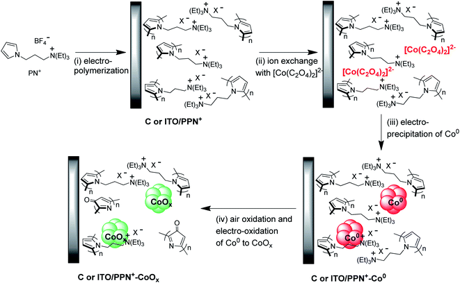
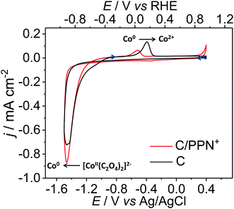
The four-step electrochemical procedure used to prepare the C or ITO/PPN+-CoOx modified electrodes is depicted in Scheme 1. For analytical electrochemical studies, C electrodes (surface of 0.071 cm2) were used for film deposition, while larger surface ITO electrodes (surface of 1.0 cm2) were employed for microscopy studies (see below). The first step consists of the electropolymerization in acetonitrile of PN+ (4 mM) at the electrode surface at an applied potential of +0.95 V vs. Ag/AgNO3 for an anodic charge of 4 mC.48 The surface coverage in ammonium units ΓN+ (mol cm−2) corresponding to the amount of polypyrrole deposited on the electrode was estimated to be 1.20 (±0.1) × 10−7 mol cm−2 by the integration of the reversible redox process of polypyrrole (see the ESI†). In a second step, the PPN+ electrode is dipped for one hour in an aqueous borate buffer at pH 6 (0.1 M Na2SO4 and 0.1 M H3BO3) containing CoSO4 (4 mM) and Na2C2O4 (20 mM), to incorporate by ion exchange within the cationic polypyrrole film47,48,52–54 an anionic cobalt oxalate complex, most probably in the form of [Co(C2O4)2]2− generated in situ. The Co0 nanoparticles were then electrogenerated within the film by the reduction of the cobalt oxalate complex inserted into the polymer at an applied potential of −1.3 V vs. Ag/AgCl for a cathodic charge of 4 mC (Fig. S1†). Of note, in this article, the potentials are given versus Ag/AgCl for all electrochemical experiments performed in aqueous solution. During this electroreduction step, the C/PPN+ modified electrode is maintained in the cobalt oxalate solution (0.1 M borate buffer at pH 6). For comparison purposes, Co0 particles were also electrodeposited on naked C electrodes (without PPN+) from the same cobalt oxalate aqueous solution using also a cathodic charge of 4 mC. Typically for Co0 electrodeposition on C and in C/PPN+ electrodes, about 130–170 s are required to pass a cathodic charge of 4 mC (Fig. S1†). A cathodic potential of −1.3 V for Co0 electrogeneration on naked C and C/PPN+ electrodes was chosen from the cyclic voltammetry (CV) of the cobalt oxalate solution recorded in borate buffer at pH 6 (Fig. 1).In the CV shown in Fig. 1, a large irreversible process corresponding to the reduction of Co2+ (coordinated to oxalate) to metallic Co0 leading to its deposition at the electrode surface starts at −1.0 V. The Co2+ reduction process is concomitant with the electrocatalytic reduction of protons to H2 catalyzed by the Co0 electrodeposited.48 In the reverse scan, the irreversible oxidation peak observed at −0.4 V for C/PPN+-Co0 (−0.5 V for C/Co0) is ascribed to the reoxidation of the electrodeposited Co0 to Co2+, which is then dissolved in water.26 Consequently, we chose to electrodeposit Co0 on C and C/PPN+ at −1.3 V, since at this potential the Co0 electrogeneration can be promoted while minimizing H2 generation. The Co loading (ΓCo) on the C/PPN+ and C electrodes was estimated to be 2.27 (±0.45) × 10−8 and 5.07 (±0.33) × 10−8 mol cm−2, corresponding to deposition yields of 7.8 and 17.4%, respectively, calculated by ICP-MS measurements. Thus, for the same quantity of charge (4 mC), the amount of Co0 deposited on the C/PPN+ film is 2.23 times smaller than that deposited on the naked C electrode. The average ΓCo/ΓN+ ratio within the C/PPN+-Co0 electrodes has been determined to be 0.19, considering the average surface coverage values of Co and PPN+, which are respectively ΓCo = 2.27 × 10⁻⁸ mol cm−2 and ΓN+ = 1.2 × 10⁻⁷ mol cm−2.
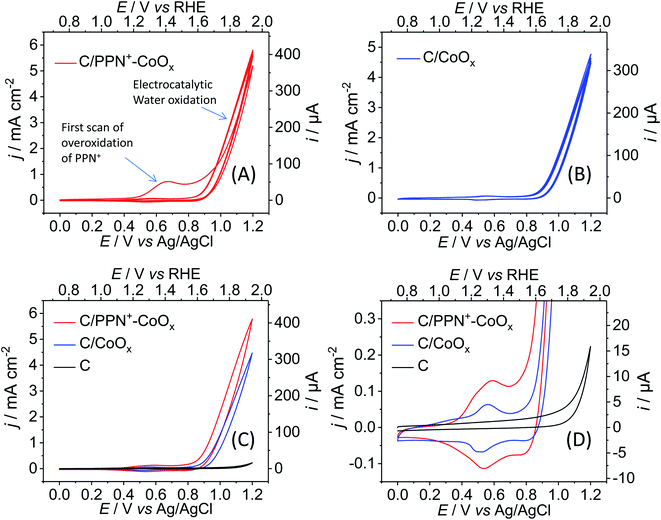
The last step is the oxidation of Co0 to cobalt oxide. Firstly, a partial oxidation of Co0 to CoO occurs almost instantaneously under air exposure during the transfer of the C/PPN+-Co0 and C/Co0 electrodes into an aqueous borate buffer solution at pH 9.2. The spontaneous air oxidation of Co0 to CoO is well known and was previously reported by the groups of Rice55 and Zhao.56 Then, to oxidize CoO to higher oxidation states than II (i.e. to CoOx), five consecutive cycles between 0 and +1.2 V were performed in a 0.1 M borate buffer solution (pH 9.2) (Fig. 2 and Scheme 1). The generation of cobalt oxide is evidenced by the appearance of its typical small intensity reversible CoII/CoIII redox process13,57,58 with anodic and cathodic peaks respectively located at +0.58 and +0.53 V for C/PPN+-CoOx, and at +0.56 and +0.51 V for C/CoOx (Fig. 2D). Increasing the number of anodic cycles does not lead to a significant increase of the CoII/CoIII redox process. The similarity of the CoII/CoIII redox processes for C/PPN+-CoOx and C/CoOx indicates that the same nature of cobalt oxide is generated on both electrodes (Fig. 2D). X-ray photoelectron spectroscopy (XPS) measurements performed on C/PPN+-CoOx after the electro-oxidation of CoO particles indeed suggest a mixture of a mixed valence cobalt oxide (Co3O4) and a cobalt oxyhydroxide (CoOOH) (see below). Note that a similar CoII/CoIII redox process in the same potential range was obtained by the group of Spiccia59 for cobalt oxide electrodeposited in a borate buffer (pH 9.2) from solutions of negatively charged cobalt complexes.
It can also be noted that in the first scan from 0 to +1.2 V of the C/PPN+-CoO electrode (Fig. 2A), two broad anodic processes are observed at +0.67 and +0.95 V in the cyclic voltammogram, which correspond respectively to the oxidation and the overoxidation of polypyrrole. The mechanism of the overoxidation of polypyrrole is complex but has been well investigated.60–62 During its overoxidation, a nucleophilic attack at α- or β-carbon of a pyrrole unit occurs, resulting in the introduction of oxygen atoms on the polymer backbone and a loss of its conductivity. After the overoxidation, the polymeric chain remains globally intact, the ammonium substituents are still present in the film and the CoOx particles stay embedded in the overoxidized polymer. Consequently, after the first scan, only the CoII/CoIII redox process is observed in the CV below +0.7 V and the redox behavior of the polypyrrole has disappeared, meaning that the polymer conductivity is fully destroyed owing to its complete overoxidation. The electronic conductivity of the PPN+-CoOx film, which is effective for potentials above +0.3 V (Fig. 2D), is thus only ensured by the cobalt oxide nanoparticles, presumably via percolation, while the overoxidized PPN+ acts as a nonconductive matrix maintaining the nanoparticles at the surface of the electrode, as we previously observed for C/PPN+-NiOx electrodes.48
The generation of the CoOx particles on C and C/PPN+ electrodes is quasi-concomitant with the catalytic water oxidation observed in their CVs (Fig. 2) by a growing catalytic current above +0.80 V. It is important to note that the catalytic current density (j) of the C/PPN+-CoOx electrode at +1.2 V is higher than that of the C/CoOx electrode, with 5.77 vs. 4.76 mA cm−2, respectively (Fig. 2A and B), evidencing the better catalytic performance of C/PPN+-CoOx in spite of the lower loading of cobalt within the polymer film. This result could be ascribed to the greater nanostructuration of the CoOx embedded into the polymeric PPN+ matrix. The difference of nanostructuration between C/PPN+-CoOx and C/CoOx, which is related to their electrochemically active surface area, can be qualitatively estimated from their CVs. The integration of the overall current of the CVs for both electrodes between +0.3 and +0.7 V (Fig. 2D) indicates that the charge involved in the redox processes leading to the insulator/conductor conversion63 of C/PPN+-CoOx as well as the CoII/CoIII conversion of redox active sites exposed to the electrolyte57 is 1.81 times greater than that of C/CoOx. Given that there is 2.23 times less cobalt in C/PPN+-CoOx compared to C/CoOx (see above), the electrochemically active surface area of the nanocomposite electrode is then estimated to be greater than that of the simple cobalt oxide electrode.
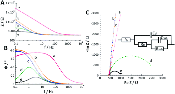
In order to confirm the higher nanostructuration of the composite material, the capacitance of C/PPN+-CoOx and C/CoOx electrodes was estimated by electrochemical impedance spectroscopy (EIS). Indeed, the capacitance of an electrode is directly correlated with its electrochemically active surface area and thus with its structuration.64–66 Bode phase and Nyquist plots (Fig. 3 and S5†) were recorded with both electrodes in borate buffer solution at pH 9.2 for different potentials (0.2, 0.6, 0.8, 0.9 and 1.0 V). The impedance spectra obtained were fitted with the equivalent circuit conventionally used for the catalytic oxidation of water.13,67–69 The equivalent circuit is shown in the inset of Fig. 3C and is composed of the resistance of the electrolyte (Rs) between the working and reference electrodes, the double layer capacitance of the working electrode (Cdl), the electron transport resistance (Rtr, also called polarization resistance) of the film (i.e. PPN+-CoOx or CoOx), and the capacitance (Csub) and resistance (Rsub) related to the charge transfer between the cobalt oxide particle and its surface intermediates involved in the water oxidation process. For the curve fitting, we chose to replace the capacities with constant phase elements (CPEs) in order to take into account the inhomogeneity of the system, which is commonly associated with nanostructured electrodes with a high roughness factor.69–72 The values of the equivalent circuit elements obtained by the experimental data fitting are reported in Table 1 and are averages calculated from measurements performed on three different electrodes for each film.
| E (V) | R tr (Ω cm−2) | C dl (mF cm−2) | n 1 | R sub (Ω cm−2) | C sub (mF cm−2) | n 2 |
|---|---|---|---|---|---|---|
| a Potentials are given versus Ag/AgCl. | ||||||
| C/PPN + -CoO x | ||||||
| 0.6 | 12 ± 1 | 0.67 ± 0.06 | 0.936 ± 0.004 | >10 (ref. 17) | — | — |
| 0.8 | 10 ± 1 | 1.1 ± 0.1 | 0.930 ± 0.006 | >10 (ref. 14) | — | — |
| 0.9 | 7.2 ± 0.5 | 1.2 ± 0.1 | 0.89 ± 0.01 | 145 ± 9 | 1.32 ± 0.09 | 0.905 ± 0.006 |
| 1.0 | 5.6 ± 0.7 | 0.8 ± 0.2 | 0.875 ± 0.006 | 30 ± 1 | 1.4 ± 0.1 | 0.91 ± 0.01 |
![[thin space (1/6-em)]](https://www.rsc.org/images/entities/char_2009.gif) |
||||||
| C/CoO x | ||||||
| 0.6 | 18 ± 1 | 0.15 ± 0.03 | 0.956 ± 0.003 | >10 (ref. 17) | — | — |
| 0.8 | 16 ± 1 | 0.30 ± 0.05 | 0.958 ± 0.003 | >10 (ref. 15) | — | — |
| 0.9 | 14 ± 1 | 0.38 ± 0.06 | 0.952 ± 0.003 | 350 ± 40 | 0.34 ± 0.06 | 0.922 ± 0.002 |
| 1.0 | 8.2 ± 0.8 | 0.30 ± 0.03 | 0.929 ± 0.007 | 40 ± 0.5 | 0.39 ± 0.07 | 0.901 ± 0.095 |
Three potential domains with different electrochemical behaviours for C/PPN+-CoOx and C/CoOx were observed by EIS, the latter being correlated with their CVs: the regions around +0.2 V, between +0.6 and +0.8 V and above +0.9 V. At a potential of +0.2 V, the impedance spectra of C/PPN+-CoOx and C/CoOx could not be correctly fitted because the impedance measured at this potential is very high and different from those of the other spectra obtained with potentials between +0.6 and +1.0 V (Fig. 3C and S5C†). Therefore only the values of the equivalent circuit elements obtained between +0.6 and +1.0 V are reported in Table 1. This corroborates the fact that no redox process of cobalt is observable in the CVs of C/PPN+-CoOx and C/CoOx in the region of +0.2 V (Fig. 2D) and both electrodes are mainly insulating in this potential region. Hence, EIS measurements confirm that the conductivity within the PPN+-CoOx film is only ensured by the cobalt oxide particles through the various oxidation states of cobalt (i.e. CoII/CoIII and CoIII/CoIV).
In the region between +0.6 and +0.8 V, the EIS spectra allow recovery of only the Cdl and Rtr parameters which are here related to the CoII/CoIII redox system. Since the water oxidation catalysis is weak or non-operative between +0.6 and +0.8 V, Rsub and Csub cannot be determined. Otherwise, EIS measurements reveal that, irrespective of the potential, the Rtr resistance is weaker for the C/PPN+-CoOx electrode than for the C/CoOx electrode, and conversely, the Cdl value of C/PPN+-CoOx is higher than those of C/CoOx. At +0.6 V in the Co(II)/Co(III) redox process (see Fig. 2D), the Cdl value of C/PPN+-CoOx (670 μF cm−2) is 4.5 times greater than that of C/CoOx (150 μF cm−2). Therefore, EIS measurements confirm that C/PPN+-CoOx exhibits greater nanostructuration than C/CoOx. At +0.8 V, Cdl values drastically increase to 1100 and 300 μF cm−2, respectively, for C/PPN+-CoOx and C/CoOx, most probably due to further oxidation of cobalt active sites leading to the onset of the OER (Fig. 2D).13
For potentials above +0.9 V, all the parameters of the equivalent circuit were recovered from the spectra. Indeed, the RsubCsub loop in the equivalent circuit correctly models the interfacial charge transfer with the surface intermediates produced during the OER,13 with the latter operating efficiently above +0.9 V. Cdl values are higher at +0.9 V (1200 μF cm−2 for C/PPN+-CoOx and 380 μF cm−2 for C/CoOx) than those at +0.6 and +0.8 V for both films for the reason mentioned above. It is worth noting that, when the potential goes from 0.9 to 1.0 V, the decrease in Cdl (800 μF cm−2 for C/PPN+-CoOx and 300 μF cm−2 for C/CoOx at 1.0 V) was ascribed by Bisquert et al.73 to the strong release of O2 bubbles obtained at the higher potentials that diminish the electrode surface area exposed to the substrate and thus reduce its capacitive behavior. The values of n1 and n2 are the parameters associated with the transition from the CPE to a pure capacity.70 When n is close to 1, it means that we are approaching a pure capacity. Here, the n values are all greater than 0.87 indicating a relatively good homogeneity70 of both film/solution interfaces, PPN+-CoOx and CoOx. This may reflect the fact that the catalytic sites are certainly distributed relatively homogeneously. In addition, the n value associated with the double-layer capacitance is slightly lower for the PPN+-CoOx film, which shows that in the presence of the polymer, the roughness at the film/solution interface is slightly greater. This increase in the film surface roughness was also observed by scanning electron microscopy (SEM) (see below and Fig. S7†). Therefore it can be envisaged that, even if the catalytic sites are distributed in a homogeneous manner for the two interfaces, the roughness of the polymer lowers very slightly the value of n1. The change in this parameter would then be an illustration of the increase in the surface area of the interface provided by the roughness of the polymer, this greater surface area inducing higher catalytic activity.
2.2. Characterization of cobalt oxide and poly(pyrrole-alkylammonium) cobalt oxide nanocomposites by AFM, TEM, SEM and XPS
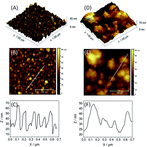
For atomic force microscopy (AFM), transmission electron microscopy (TEM) and scanning electron microscopy (SEM) studies, the films of PPN+-CoOx or CoOx were deposited on ITO electrodes (surface of 1.0 cm2). ITO/PPN+-CoOx and ITO/CoOx electrodes were prepared with a charge of 56 mC for both the PPN+ and Co0 deposition to obtain a charge density of 56 mC cm−2, similar to that used for the preparation of the C/PPN+-CoOx and C/CoOx electrodes (4 mC for a C electrode with a surface of 0.071 cm2) (see ESI† Section 3 for more details).The surface topography of ITO/PPN+-CoOx and ITO/CoOx electrodes was studied by AFM (Fig. 4). The 3D and 2D AFM images for ITO/CoOx display a homogeneous nodular topography composed of aggregated CoOx particles with a root-mean square (r.m.s.) roughness of 10.2 nm (Fig. 4A and B), while the images of ITO/PPN+-CoOx exhibit an ill-defined cauliflower-like topography with a similar r.m.s. roughness of 11.6 nm (Fig. 4D and E). Such a cauliflower topology is usually observed for electrodeposited polypyrrole films.47,48,74 From the height profile analysis of the AFM image of ITO/CoOx (Fig. 4C), the size of CoOx nodules was estimated to be 58 ± 31 nm. For ITO/PPN+-CoOx, nanoparticles of CoOx are buried within the PPN+ film preventing the determination of the particle size by AFM. Secondary electron SEM images also confirmed the nodular and cauliflower morphologies observed for ITO/CoOx and ITO/PPN+-CoOx, respectively (Fig. S7†).
To further characterize the size of CoOx particles electrogenerated inside the PPN+ film or directly electrodeposited on the electrode surface, the PPN+-CoOx and CoOx materials were observed by TEM (Fig. 5). PPN+-CoOx and CoOx fragments of films were scraped off from the ITO plates and deposited on carbon-coated copper grids. TEM images reveal large agglomerates (>100 nm) of CoOx nanoparticles for ITO/CoOx (Fig. 5A), while for ITO/PPN+-CoOx the cobalt nanoparticles are not aggregated and are well-dispersed in the polymer film with an average particle size of 31 ± 20 nm (Fig. 5B). These images clearly show that the PPN+ polymer prevents the nanoparticle agglomeration, resulting in a larger electrochemically active surface area of PPN+-CoOx compared to that obtained from a direct electrodeposition of CoOx on the electrode surface.
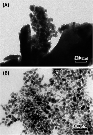 | ||
| Fig. 5 TEM images of (A) CoOx (56 mC used for Co0 deposition on ITO, scale 100 nm) and (B) PPN+-CoOx nanocomposite (56 mC used for PPN+ deposition and subsequent Co0 deposition on ITO, scale 100 nm). | ||
The nature of the electrogenerated cobalt oxide particles within the PPN+ film, after 5 cycles between 0 and +1.2 V in 0.1 M borate buffer (pH 9.2), was also studied by X-ray photoelectron spectroscopy (XPS) measurements (Fig. 6 and S6†). For XPS analysis, PPN+-CoOx was electrodeposited on carbon pellets (6 mm of diameter, denoted as Cpel) which can be easily removed from the electrode support by unscrewing and placed in the vacuum chamber of the spectrometer (see ESI† Section 3 for their preparation and Section 10 for XPS measurement). High resolution XPS spectroscopy of the Co 2p3/2 region reveals a broad signal, which could be deconvoluted into a series of peaks corresponding to various transitions (shake-up, plasmon loss, satellites, etc.) due to the complex nature of this transition metal (Fig. 6). The deconvolution of the peak at ca. 781 eV indicates that the cobalt deposit for the Cpel/PPN+-CoOx anode could be a mixture of a mixed valence cobalt oxide (Co3O4) and a cobalt oxyhydroxide (CoOOH).75 Foelske et al.76 demonstrated by coupling electrochemical experiments with XPS measurements that poising an electrode of metallic cobalt at a potential superior to +1.18 V vs. Ag/AgCl in a borate buffer at pH 9.3 results in the formation of a Co3O4 layer on its surface. In parallel, the group of Spiccia59 demonstrated by X-ray absorption fine structure measurements (EXAFS) that cobalt oxide, electrodeposited in a borate buffer (pH 9.2) by oxidizing a cobalt complex, closely resembles the heterogeneous CoOOH phase. Given the similarities between our study and that of Spiccia59 in the electrochemical behavior of CoOx in borate buffer at the same pH 9.2 (see discussion above), as well as with the study of Foelske76 in the electrogeneration of CoOx from Co0 in borate buffer, we can assume that our cobalt oxide within PPN+ could indeed contain a mixture of both Co3O4 and CoOOH species.
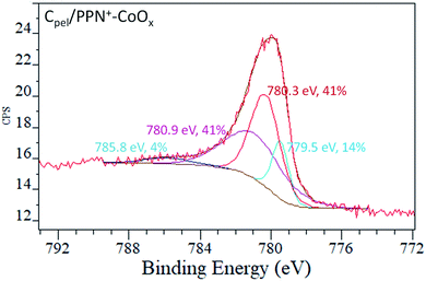 | ||
| Fig. 6 XPS spectra (Co 2p3/2 region) of the electrode surfaces of Cpel/PPN+-CoOx after 5 cycles between 0 and +1.2 V vs. Ag/AgCl in a 0.1 M borate buffer (pH 9.2). | ||
2.3. Electrocatalytic performance of cobalt oxide and poly(pyrrole-alkylammonium) cobalt oxide nanocomposite electrodes
The electrocatalytic activity of C/PPN+-CoOx and C/CoOx electrodes has been investigated by cyclic voltammetry under mild basic conditions in a borate buffer solution at pH 9.2 (Fig. 2). Table 2 summarizes the catalytic OER performance of these modified electrodes and that of C/PPN+-NiOx recently reported by our group48 in a 0.1 M borate buffer solution at pH 9.2 together with those of cobalt oxide-based electrodes reported in the literature in a similar medium. In all reported cases, cobalt oxide was electrogenerated on the surface of fluorine doped tin oxide electrodes (FTO). Developing electrolyzers operating at nearly neutral pH, such as pH 9.2, is of utmost importance in view of avoiding the corrosion issue under strongly acidic or alkaline conditions.11 Herein, the C/PPN+-CoOx anode exhibits a j value of 4.04 mA cm−2 at a η of +0.61 V and a η value of +0.44 V at 1 mA cm−2 with a cobalt mass loading of 1.34 μg cm−2. This performance places our nanocomposite anode among the best reported cobalt oxide-based anodes for water oxidation operating in a 0.1 M borate buffer solution at pH 9.2.| Catalyst/electrode | j (mA cm−2)@η (V) | η (V)@j (mA cm−2) | Metal mass loading (μg cm−2) | Mass activity (A mg−1)@η (V) | TOFmin (s−1)@η (V) | Author et al. (ref.) |
|---|---|---|---|---|---|---|
| a Values were extrapolated from the cyclic voltammograms reported by the authors. b Data non calculated by the authors but estimated herein from the current density (j) at defined overpotentials (η) and the mass loading of Co given in the article. c The current density was measured from cyclic voltammetry corrected for the ohmic drop. nd: not determined. FTO: fluorine doped tin oxide electrode. | ||||||
| C/PPN+-CoOx | 4.04@0.61 | 0.44@1 | 1.34 | 3.01@0.61 | 0.46@0.61 | This work |
| C/PPN+-CoOx | 2.17@0.51 | 1.34 | 1.62@0.51 | 0.25@0.51 | This work | |
| C/PPN+-CoOx | 0.53@0.40 | 1.34 | 0.40@0.40 | 0.06@0.40 | This work | |
| C/CoOx | 3.40@0.61 | 0.46@1 | 2.99 | 1.14@0.61 | 0.17@0.61 | This work |
| C/CoOx | 1.32@0.51 | 2.99 | 0.44@0.51 | 0.07@0.51 | This work | |
| C/CoOx | 0.22@0.40 | 2.99 | 0.07@0.40 | 0.01@0.40 | This work | |
| C/PPN+-NiOx | 2.17@0.61 | 0.51@1 | 1.9 | 1.12@0.61 | 0.17@0.61 | Fortage48 |
| FTO/CoOx | 2.89a@0.51 | 0.37a@1 | nd | nd | nd | Nocera24 |
| FTO/CoOx | 0.41@0.40 | 0.53@1 | 46.0 | 0.009b@0.40 | 0.001b@0.40 | Nocera28 |
| FTO/CoOx | 1.90a@0.61 | 0.51a@1 | 1.11 | 1.71b@0.61 | 0.26b@0.61 | Spiccia59 |
| FTO/CoOx | 0.39a@0.61 | 0.75a@1 | 0.003 | 130b@0.61 | 20@0.61 | Sun79 |
| FTO/CoOx | 2.60c@0.61 | nd | nd | nd | nd | Du77 |
| FTO/CoOx | 1.40c@0.61 | 0.51a@1 | 3.53 | 0.40b@0.61 | 0.06b@0.61 | Du78 |
For comparison, the C/CoOx anode presents a j value of 3.40 mA cm−2 at a η of +0.61 V and a η value of +0.46 V at 1 mA cm−2 with a cobalt mass loading of 2.99 μg cm−2. The C/PPN+-CoOx nanocomposite electrode presents a higher j and a lower η values compared to those of C/CoOx with ∼2.2 times less cobalt loading, demonstrating the beneficial effect of using a poly(pyrrole-alkylammonium) matrix to enhance the nanostructuration of the electrode material and thus its electrocatalytic performance. Of note, in the three compartment cell, the resistance R between the anode (i.e. the working electrode) and the Ag/AgCl reference, which causes the ohmic drop (related to the iR value) in the cell, could be different between C/PPN+-CoOx and C/CoOx, making the comparison of their electrocatalytic performance unfair. In view of suppressing the ohmic drop and making a fair comparison, the resistance R in the cell has been determined to be 1 and 4.6 Ω respectively with C/PPN+-CoOx and C/CoOx. Since these R values are low, the CVs and the catalytic current density of both electrodes are weakly affected by the iR correction (see in the ESI the CVs with and without iR correction; Fig. S2†), which means that the previous comparison of the catalytic activities of both anodes was correct. According to TEM images and EIS measurements, C/PPN+-CoOx contains small CoOx particles (31 nm) with a capacitance of 670 μF cm−2, while C/CoOx exhibits big agglomerates of CoOx particles (>100 nm) associated with a lower capacitance of 150 μF cm−2 (see above). Hence the higher catalytic activity of the C/PPN+-CoOx nanocomposite compared to the direct deposition C/CoOx can be directly correlated with a greater nanostructuration of the nanocomposite that increases the electrochemically active surface area of the anode and ensures a great accessibility of the active catalytic sites towards substrates such as water or OH− ions. The higher values of mass activity and turnover frequency (TOF) of C/PPN+-CoOx (3.01 A mg−1 and 0.46 s−1) compared to those of C/CoOx (1.14 A mg−1 and 0.17 s−1) at pH 9.2 at an overpotential of 0.61 V confirm the higher OER catalytic activity of the nanocomposite PPN+-CoOx material (Table 2). In order to facilitate the comparison with the electrocatalytic performance of previously reported anodes based on cobalt oxide operating at pH 9.2 with a 0.1 M borate buffer (Table 2), the CVs of C/PPN+-CoOx have been recorded at different scan rates between 5 and 100 mV s−1 (Fig. S3†), since various scan rates have been used to measure the performance of the reported anodes. The CVs of C/PPN+-CoOx are weakly impacted by the scan rate value, indicating that the diffusion of the borate buffer in the polypyrrole film is efficient. In other words, the electrocatalytic activity of C/PPN+-CoOx measured with a scan rate of 50 mV s−1 is reliable to make a fair comparison with those of the reported anodes. It appears that the mass activity and TOF values of the C/PPN+-CoOx electrode are among the highest in the literature (Table 2). Otherwise, although the CoOx films of the literature have been realized with the same range of mass loadings (1–4 μg cm−2) as that of the PPN+-CoOx nanocomposite, the comparison of the performances of these anodes is not easy and could be erroneous due to the fact all the oxide deposits reported in Table 2 were made on an FTO electrode (i.e. fluorine tin oxide) as a conductive support, whose conductivity is lower than that of a carbon electrode, thus possibly decreasing the overall performance of the anodes. Otherwise, it is worth noting that the comparison of the electrocatalytic activities of anodes, for which the ohmic drop correction is applied, such as those reported by Du77,78 in Table 2, is relevant. One can see that the catalytic currents of C/PPN+-CoOx and C/CoOx (respectively 4.04 and 3.40 mA cm−2 at η = 0.61 V) are higher than those of the FTO/CoOx anodes (2.60 and 1.40 mA cm−2 at η = 0.61 V),77,78 in spite of the iR correction and the higher cobalt loading on FTO/CoOx in ref. 78 (3.53 μg cm−2vs. 1.34 and 2.99 μg cm−2 for C/PPN+-CoOx and C/CoOx respectively). It is also interesting to note that the OER performance of C/PPN+-CoOx is greater than that of the analogous C/PPN+-NiOx previously reported by our group,48 which displays lower values of j (2.17 mA cm−2), mass activity (1.12 A mg−1) and TOF (0.17 s−1) for an overpotential of 0.61 V. If we consider a similar nanostructuration for C/PPN+-CoOx and C/PPN+-NiOx anodes (particle sizes of CoOx and NiOx (ref. 48) within PPN+ of 31 and 21 nm, respectively) and a lower metal loading of cobalt compared to that of nickel (ΓCo ∼ 23 nmol cm−2vs. ΓNi ∼ 33 nmol cm−2),48 CoOx particles display a higher intrinsic catalytic activity than NiOx for water oxidation in borate buffer at pH 9.2.
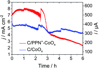
The stability of C/PPN+-CoOx and C/CoOx electrodes at pH 9.2 in a 0.1 M borate buffer was evaluated by chronoamperometry measurements over a period of about 2 h at an applied potential of +1.2 V vs. Ag/AgCl (Fig. 7). The current density of the C/CoOx electrode decreases from 6 to 5.30 mA cm−2 after 5 min of electrolysis and then gradually decreases to reach a pseudo-plateau at 4.90 mA cm−2 after 2.5 h of electrolysis. Meanwhile the current density of C/PPN+-CoOx increases during the first hour from 7.16 to 7.80 mA cm−2 and then gradually decreases to reach a pseudo-plateau at 7.00 mA cm−2 after 2.5 h of electrolysis. Over this time range, the catalytic current of C/PPN+-CoOx is relatively stable and 1.43 times higher than that of C/CoOx, even though there is 2.2 times less cobalt in the former. Once again, this demonstrates the superiority of the nanocomposite electrode over a simple Co-based electrode.
Unfortunately, the current density of C/PPN+-CoOx decreases suddenly and drastically after 2.5 h of electrolysis reaching 2.36 mA cm−2 after 6 h of electrolysis, whereas the current density of C/CoOx decreases slowly until 4.3 mA cm−2 over the same period of time. As we previously observed for the C/PPN+-NiOx anode,48 the decrease of catalytic current with C/PPN+-CoOx is not due to the decomposition of the material or to the gradual release of cobalt oxide particles but to the partial film detachment from the carbon electrode induced by the oxygen bubbles released during the electrolysis (see in Picture S1 in the ESI,† the view of a C/PPN+-CoOx electrode before and after the electrolysis for 6 h, and the view of the PPN+-CoOx film floating in the borate electrolyte after its partial detachment from the C electrode induced by the electrolysis). Note that the relatively good stability of C/CoOx (i.e. without PPN+) could be ascribed to the good physisorption of the cobalt oxide on the carbon electrode and also to the self-healing phenomenon occurring during electrocatalytic water oxidation with cobalt oxide in a borate buffer.25,80,81
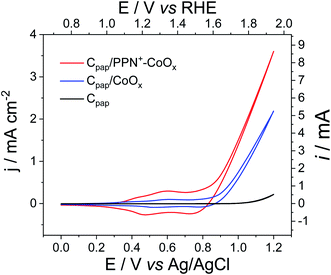
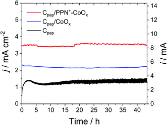
To avoid the film detachment from the electrode surface under prolonged electrolysis at +1.2 V, the physisorption of the polypyrrole film on the electrode has been increased by the electrodeposition of the PPN+-CoOx material on a carbon paper electrode (denoted as Cpap) with a high roughness and a larger surface of 2.4 cm2, following the same procedure used for the preparation of the PPN+-CoOx nanocomposite on a small glassy carbon electrode (see Section 3 in the ESI for its preparation and Fig. S4A†). The deposition of the PPN+-CoOx film on the Cpap electrode was evidenced by SEM images (Fig. 8A and B) and EDX spectroscopy (Fig. 8C) by comparison with a pristine Cpap electrode (Fig. S8†). The EDX spectrum of Cpap exhibits only the characteristic peaks of C and O atoms respectively at 0.28 and 0.50 keV (Fig. S8C†), while the EDX spectrum of C/PPN+-CoOx displays broader peaks below 0.6 keV ascribed to the C, N and O atoms of the overoxidized polypyrrole film, in addition to the C/O peaks of Cpap (see above), along with the typical peaks of cobalt at 0.78 (Lα) and 6.92 keV (Kα) (Fig. 8C). As observed above on the CV of C/PPN+-CoOx recorded in a borate buffer at pH 9.2 (Fig. 2), Cpap/PPN+-CoOx displays the redox signature of CoII/CoIII between 0.3 and 0.8 V vs. Ag/AgCl with a strong catalytic current attributed to water oxidation to O2, reaching 3.6 mA cm−2 at 1.2 V vs. Ag/AgCl (Fig. 9 and S4†). Otherwise, on this rough support, no PPN+-CoOx film detachment is observed and the catalytic current of Cpap/PPN+-CoOx is stable over 43 h of electrolysis at a constant potential of +1.2 V vs. Ag/AgCl in a borate buffer at pH 9.2 (Fig. 10). In addition, the stability of the catalytic current is a good indication of the stability of the CoOx nanoparticles which remain embedded in the PPN+ film during electrocatalysis. This is confirmed by the post-electrolysis characterizations of the PPN+-CoOx material deposited on Cpap.
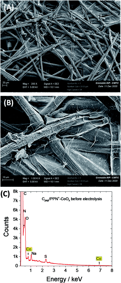 | ||
| Fig. 8 SEM images of the Cpap/PPN+-CoOx electrode at (A) 200× magnification and (B) 1000× magnification and (C) corresponding EDX spectrum. | ||
Indeed, the stability of the film on Cpap allows us to perform post-electrolysis characterization by SEM and EDX on this electrode material. Post-electrolysis characterization on ITO electrodes was not possible due to the detachment of the PPN+-CoOx film under electrolysis at +1.2 V. The SEM images and EDX spectra of Cpap/PPN+-CoOx before (Fig. 8) and after 43 h of electrolysis (Fig. 11 and 12) are very similar. The EDX spectra exhibit the same signals with similar intensity for the C/N/O peaks below 0.6 keV and for cobalt at 0.78 and 6.92 keV (Fig. 12). This result strongly indicates that the overoxidized PPN+ film and the embedded CoOx nanoparticles remain unchanged even after being maintained at +1.2 V vs. Ag/AgCl in a borate buffer at pH 9.2 over such a long period of time. The PPN+ film thus imparts a great stability to the nanocomposite material by preventing the corrosion and the degradation of CoOx nanoparticles, in addition to the phenomenon of self-healing that is known for cobalt oxide in a borate buffer.25,80,81 We also verified the formation of oxygen by gas chromatography. A high faradaic yield of 97% towards O2 evolution was measured after 2 h of electrolysis (see ESI† Section 12), confirming that Cpap/PPN+-CoOx is an efficient and selective anode for water oxidation to O2.
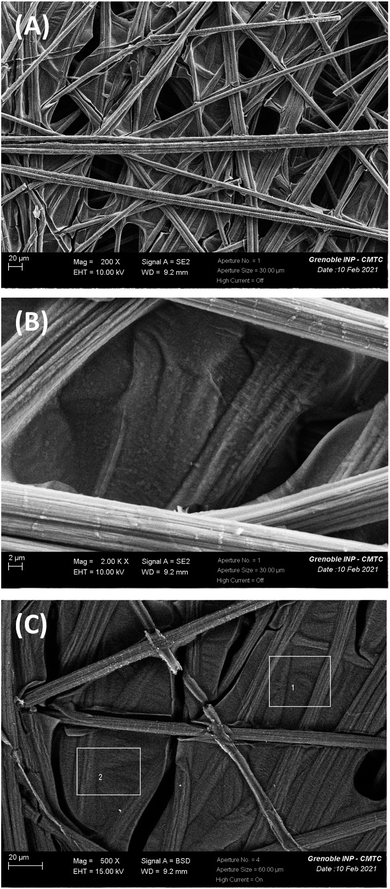 | ||
| Fig. 11 SEM image of the Cpap/PPN+-CoOx electrode: (A) 200× magnification, (B) 2000× magnification and (C) 500× magnification, along with zones 1 and 2 for which EDX analysis (see below Fig. 12) has been performed on the Cpap/PPN+-CoOx electrode after electrolysis for 43 h at 1.2 V vs. Ag/AgCl in a 0.1 M borate buffer (pH 9.2). | ||
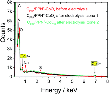 | ||
| Fig. 12 EDX spectra of the SEM images respectively in Fig. 11 of Cpap/PPN+-CoOx before (red) and after electrolysis for 43 h at +1.2 V vs. Ag/AgCl in a 0.1 M borate buffer (pH 9.2) performed in zone 1 (black) and in zone 2 (green). | ||
To compare the performance of the PPN+-CoOx nanocomposite with that of a simple CoOx film, CoOx was also electrodeposited on the rough Cpap electrode (without PPN+). The CV of Cpap/CoOx exhibits a similar CoII/CoIII signature between 0.3 and 0.8 V vs. Ag/AgCl, but despite a cobalt loading 3.5 times higher (3.70 ± 0.27 × 10⁻⁸ mol cm−2) than that on Cpap/PPN+ (1.04 ± 0.16 × 10⁻⁸ mol cm−2), the corresponding catalytic current density of 2.37 mA cm−2 at 1.2 V remains lower than that of Cpap/PPN+-CoOx (3.61 mA cm−2) (Fig. 9 and S4†), further demonstrating the benefits of using PPN+ films. It is interesting to note that, after a long electrolysis for 43 h at 1.2 V vs. Ag/AgCl in a borate buffer at pH 9.2, the catalytic current of Cpap/CoOx is also very stable (Fig. 10) as previously observed on a small carbon electrode with C/CoOx, most probably due to the self-healing phenomenon.25
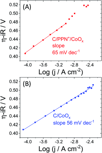
To obtain some mechanistic information, Tafel analysis was performed through stepwise chronoamperometry at pH 9.2 on C/PPN+-CoOx and C/CoOx electrodes (Fig. 13, see Section 7 in the ESI for more details†). A Tafel slope value of 56 mV dec−1 was determined for C/CoOx corresponding to a fast equilibrated electron transfer. The catalytic process is thus not controlled by an electron transfer but by a chemical step following this electron transfer.13,26,82 Similar values were reported with cobalt oxide catalysts in borate buffer at pH 9.2 by several groups such as those of Nocera,28 Du77,78 and Spiccia.59 For C/PPN+-CoOx, a Tafel slope of 65 mV dec−1, close to that of C/CoOx, was estimated within a region of corrected overpotentials between +0.41 and +0.47 V (i.e. within a potential region between +0.9 and +1.02 V vs. Ag/AgCl). Above +0.47 V, the Tafel plot of C/PPN+-CoOx deviates from linearity most probably due to the limitations by mass transport of the buffer within the polypyrrole film, which could not be easily obviated by the rotation of the electrode.83 However, the similar Tafel slopes of C/PPN+-CoOx and C/CoOx confirm that the O2 evolution occurring with these two electrodes involves the same catalytic mechanism.
3. Conclusion
We prepared a very efficient OER anode material based on a cobalt oxide-poly(pyrrole-alkylammonium) nanocomposite deposited on an electrode surface by an easy all-electrochemical procedure. TEM images and EIS measurements evidenced the high nanostructuration of the PPN+-CoOx nanocomposite owing to the small CoOx nanoparticles of ca. 30 nm well dispersed and not aggregated in the polypyrrole film. The nature of the cobalt oxide has also been identified by XPS as potentially being a mixture of Co3O4/CoOOH. By comparison with CoOx directly deposited on an electrode surface (CoOx particles > 100 nm), we demonstrated that the high nanostructuration of the composite material is the origin of the higher OER electrocatalytic performances. The nanocomposite material exhibits an exceptional mass activity of 3.01 A mg−1 and TOF values of 0.46 s−1 along with a faradaic yield of 97% for water oxidation at mildly basic pH 9.2 at an overpotential of 0.61 V, and a Tafel slope of 65 mV dec−1. The cobalt oxide–polypyrrole nanocomposite electrode is among the most efficient cobalt oxide-based anodes previously reported operating in a 0.1 M borate buffer solution at pH 9.2, but it also outperforms cobalt oxide electrogenerated on a naked electrode surface by the same electrochemical procedure. In addition, when the PPN+-CoOx material is electrodeposited on a rough carbon paper, the physisorption of the nanocomposite film is considerably enhanced and consequently its catalytic activity is very stable beyond 43 h of electrolysis. Post-electrolysis characterization by SEM and EDX also confirms the integrity of the PPN+-CoOx material after many hours of electrocatalysis. This work demonstrates the beneficial role of a positively charged polypyrrole matrix in the preparation of small particles of cobalt oxide and in the achievement of a highly stable and active anode for water oxidation. The elaboration of such a polypyrrole-metal oxide nanocomposite material could be easily extended to other abundant first-row transition metals such as manganese and iron, and also could be useful to prepare mixed metal oxides such as NiFeOx or CoFeOx, which are the most efficient OER catalysts under alkaline or mildly basic conditions.Conflicts of interest
There are no conflicts to declare.Acknowledgements
ANID (ex Becas-Chile-Conicyt) “Programa de formación de capital humano avanzado” for the PhD fellowship of D. V. M. (No. 72150091) and C. N. A. (No. 72170399), ANID/FONDECYT Postdoctoral project of D. V. M. (Grant No. 3200467), “Université Grenobles Alpes” for the PhD fellowship of B. D., The CMTC platform of “Institut Poolythechinique de Grenoble” for SEM-EDX measurements, the NanoBio-ICMG Platform (UAR 2607, Grenoble) for granting access to the Electron Microscopy facility, the ECOS-CONICYT exchange program (C13E01), Ministères de l'Europe et des Affaires Etrangères (MEAE) et de l'Enseignement Supérieur, de la Recherche et de l’Innovation (MESRI) (PHC Brancusi program (43546QA)) and the COST CM1202 program (PERSPECT H2O) are acknowledged. This work has been partially supported by LabEx Arcane and CBH-EUR-GS (ANR-17-EURE-0003).References
- A. A. Gewirth and M. S. Thorum, Inorg. Chem., 2010, 49, 3557 CrossRef CAS PubMed
.
- O. Z. Sharaf and M. F. Orhan, Renew. Sustain. Energy Rev., 2014, 32, 810 CrossRef CAS
.
- N. Armaroli and V. Balzani, ChemSusChem, 2011, 4, 21 CrossRef CAS PubMed
.
- T. R. Cook, D. K. Dogutan, S. Y. Reece, Y. Surendranath, T. S. Teets and D. G. Nocera, Chem. Rev., 2010, 110, 6474 CrossRef CAS PubMed
.
-
F. Ausfelder and A. Bazzanella, in Hydrogen Science and Engineering: Materials, Processes, Systems and Technology, ed. D. Stolten and B. Emonts, Wiley-VCH, 2016, vol. 1, p. 19 Search PubMed
.
- K. Ayers, N. Danilovic, R. Ouimet, M. Carmo, B. Pivovar and M. Bornstein, Annu Rev Chem Biomol, 2019, 10, 219 CrossRef CAS PubMed
.
- K. E. Ayers, E. B. Anderson, C. B. Capuano, B. D. Carter, L. T. Dalton, G. Hanlon, J. Manco and M. Niedzwiecki, ECS Trans., 2010, 33, 3 CrossRef CAS
.
-
J. Mergel, D. L. Fritz and M. Carmo, in Hydrogen Science and Engineering : Materials, Processes, Systems and Technology, ed. D. Stolten and B. Emonts, Wiley-VCH, 2016, vol. 1, p. 331 Search PubMed
.
-
D. Zhang and K. Zeng, in Hydrogen Science and Engineering : Materials, Processes, Systems and Technology, ed. D. Stolten and B. Emonts, Wiley-VCH, 2016, vol. 1, p. 283 Search PubMed
.
- G. Gahleitner, Int. J. Hydrogen Energy, 2013, 38, 2039 CrossRef CAS
.
- P. Li, R. Zhao, H. Chen, H. Wang, P. Wei, H. Huang, Q. Liu, T. Li, X. Shi, Y. Zhang, M. Liu and X. Sun, Small, 2019, 15, 1805103 CrossRef PubMed
.
- J. O. M. Bockris, J. Chem. Phys., 1956, 24, 817 CrossRef CAS
.
- R. L. Doyle, I. J. Godwin, M. P. Brandon and M. E. G. Lyons, PhysChemChemPhys, 2013, 15, 13737 RSC
.
- M. D. Kärkäs, O. Verho, E. V. Johnston and B. Åkermark, Chem. Rev., 2014, 114, 11863 CrossRef PubMed
.
- J. D. Blakemore, R. H. Crabtree and G. W. Brudvig, Chem. Rev., 2015, 115, 12974 CrossRef CAS PubMed
.
- P. Benson, G. W. D. Briggs and W. F. K. Wynne-Jones, Electrochim. Acta, 1964, 9, 281 CrossRef CAS
.
- V. Y. Shafirovich and V. V. Strelets, Nouv. J. Chim., 1978, 2, 199 CAS
.
- S. M. Jasem and A. C. C. Tseung, J. Electrochem. Soc., 1979, 126, 1353 CrossRef CAS
.
- L. D. Burke, M. E. Lyons and O. J. Murphy, J. Electroanal. Chem., 1982, 132, 247 CrossRef CAS
.
- Y. W. D. Chen and R. N. Noufi, J. Electrochem. Soc., 1984, 131, 731 CrossRef CAS
.
- S. P. Jiang and A. C. C. Tseung, J. Electrochem. Soc., 1991, 138, 1216 CrossRef CAS
.
- E. B. Castro, C. A. Gervasi and J. R. Vilche, J. Appl. Electrochem., 1998, 28, 835 CrossRef CAS
.
- M. W. Kanan and D. G. Nocera, Science, 2008, 321, 1072 CrossRef CAS PubMed
.
- Y. Surendranath, M. Dinca and D. G. Nocera, J. Am. Chem. Soc., 2009, 131, 2615 CrossRef CAS PubMed
.
- D. A. Lutterman, Y. Surendranath and D. G. Nocera, J. Am. Chem. Soc., 2009, 131, 3838 CrossRef CAS PubMed
.
- Y. Surendranath, M. W. Kanan and D. G. Nocera, J. Am. Chem. Soc., 2010, 132, 16501 CrossRef CAS PubMed
.
- M. W. Kanan, J. Yano, Y. Surendranath, M. Dinca, V. K. Yachandra and D. G. Nocera, J. Am. Chem. Soc., 2010, 132, 13692 CrossRef CAS PubMed
.
- A. J. Esswein, Y. Surendranath, S. Y. Reece and D. G. Nocera, Energy Environ. Sci., 2011, 4, 499 RSC
.
- J. B. Gerken, E. C. Landis, R. J. Hamers and S. S. Stahl, ChemSusChem, 2011, 3, 1176 CrossRef PubMed
.
- J. B. Gerken, J. G. McAlpin, J. Y. C. Chen, M. L. Rigsby, W. H. Casey, R. D. Britt and S. S. Stahl, J. Am. Chem. Soc., 2011, 133, 14431 CrossRef CAS PubMed
.
- Y. Liang, Y. Li, H. Wang, J. Zhou, J. Wang, T. Regier and H. Dai, Nat. Mater., 2011, 10, 780 CrossRef CAS PubMed
.
- Y. Surendranath, D. A. Lutterman, Y. Liu and D. G. Nocera, J. Am. Chem. Soc., 2012, 134, 6326 CrossRef CAS PubMed
.
- S. Cobo, J. Heidkamp, P.-A. Jacques, J. Fize, V. Fourmond, L. Guetaz, B. Jousselme, V. Ivanova, H. Dau, S. Palacin, M. Fontecave and V. Artero, Nat. Mater., 2012, 11, 802 CrossRef CAS PubMed
.
- C. L. Farrow, D. K. Bediako, Y. Surendranath, D. G. Nocera and S. J. L. Billinge, J. Am. Chem. Soc., 2013, 135, 6403 CrossRef CAS PubMed
.
- T. Y. Ma, S. Dai, M. Jaroniec and S. Z. Qiao, J. Am. Chem. Soc., 2014, 136, 13925 CrossRef CAS PubMed
.
- Y. Liu and D. G. Nocera, J. Phys. Chem. C, 2014, 118, 17060 CrossRef CAS
.
- N. Jiang, B. You, M. Sheng and Y. Sun, Angew. Chem., Int. Ed., 2015, 54, 6251 CrossRef CAS PubMed
.
- H. Kim, J. Park, I. Park, K. Jin, S. E. Jerng, S. H. Kim, K. T. Nam and K. Kang, Nat. Commun., 2015, 6, 8253 CrossRef CAS PubMed
.
- Y. Zhao, S. Chen, B. Sun, D. Su, X. Huang, H. Liu, Y. Yan, K. Sun and G. Wang, Sci. Rep., 2015, 5, 7629 CrossRef CAS PubMed
.
- G. Gardner, J. Al-Sharab, N. Danilovic, Y. B. Go, K. Ayers, M. Greenblatt and G. Charles Dismukes, Energy Environ. Sci., 2016, 9, 184 RSC
.
- H. Chen, Y. Gao and L. Sun, ChemCatChem, 2016, 8, 2757 CrossRef CAS
.
- L. Han, S. Dong and E. Wang, Adv. Mater., 2016, 28, 9266 CrossRef CAS PubMed
.
- J. Wang, W. Cui, Q. Liu, Z. Xing, A. M. Asiri and X. Sun, Adv. Mater., 2016, 28, 215 CrossRef CAS PubMed
.
- Y. Chen, J. Hu, H. Diao, W. Luo and Y.-F. Song, Chem. Eur. J., 2017, 23, 4010 CrossRef CAS PubMed
.
- I. Roger, M. A. Shipman and M. D. Symes, Nat. Rev. Chem., 2017, 1, 0003 CrossRef CAS
.
- S. E. S. El Wakkad and A. Hickling, Trans. Faraday Soc., 1950, 46, 820 RSC
.
- Y. Lattach, J. F. Rivera, T. Bamine, A. Deronzier and J.-C. Moutet, ACS Appl. Mater. Interfaces, 2014, 6, 12852 CrossRef CAS PubMed
.
- D. V. Morales, C. N. Astudillo, Y. Lattach, B. F. Urbano, E. Pereira, B. L. Rivas, J. Arnaud, J.-L. Putaux, S. Sirach, S. Cobo, J.-C. Moutet, M.-N. Collomb and J. Fortage, Catal. Sci. Technol., 2018, 8, 4030 RSC
.
- X. Cao, W. Yan, C. Jin, J. Tian, K. Ke and R. Yang, Electrochim. Acta, 2015, 180, 788 CrossRef CAS
.
- L. Liu, Y. Hou, J. Wang, J. Chen, H.-K. Liu, Y. Wu and J. Wang, Adv. Mater. Interfaces, 2016, 3, 1600030 CrossRef
.
- Z. B. Shifrina, V. G. Matveeva and L. M. Bronstein, Chem. Rev., 2020, 120, 1350 CrossRef CAS PubMed
.
- A. Zouaoui, O. Stephan, M. Carrier and J. C. Moutet, J. Electroanal. Chem., 1999, 474, 113 CrossRef CAS
.
- A. Zouaoui, O. Stephan, A. Ourari and J. C. Moutet, Electrochim. Acta, 2000, 46, 49 CrossRef CAS
.
- Y. Lattach, A. Deronzier and J.-C. Moutet, ACS Appl. Mater. Interfaces, 2015, 7, 15866 CrossRef CAS PubMed
.
- D. W. Rice, P. B. P. Phipps and R. Tremoureux, J. Electrochem. Soc., 1979, 126, 1459 CrossRef CAS
.
- B. H. R. Suryanto, X. Lu, H. M. Chan and C. Zhao, RSC Adv., 2013, 3, 20936 RSC
.
- C. Costentin, T. R. Porter and J.-M. Savéant, J. Am. Chem. Soc., 2016, 138, 5615 CrossRef CAS PubMed
.
- C. N. Brodsky, D. K. Bediako, C. Shi, T. P. Keane, C. Costentin, S. J. L. Billinge and D. G. Nocera, ACS Appl. Energy Mater., 2019, 2, 3 CrossRef CAS
.
- S. A. Bonke, M. Wiechen, R. K. Hocking, X.-Y. Fang, D. W. Lupton, D. R. MacFarlane and L. Spiccia, ChemSusChem, 2015, 8, 1394 CrossRef CAS PubMed
.
- A. S. Liu and M. A. S. Oliveira, Mater. Res., 2007, 10, 205 CrossRef CAS
.
- S. P. Ozkorucuklu, Y. Sahin and G. Alsancak, Sensors, 2008, 8, 8463 CrossRef CAS PubMed
.
-
T. W. Lewis, A Study of the Overoxidation of the Conducting Polymer Polypyrrole, Doctor of Philosophy thesis, Department of Chemistry, University of Wollongong, 1998, http://ro.uow.edu.au/theses/1107
.
- C. Costentin, T. R. Porter and J.-M. Savéant, ACS Appl. Mater. Interfaces, 2019, 11, 28769 CrossRef CAS PubMed
.
- S. Trasatti and O. A. Petrii, Pure Appl. Chem., 1991, 63, 711 CAS
.
- M. W. Louie and A. T. Bell, J. Am. Chem. Soc., 2013, 135, 12329 CrossRef CAS PubMed
.
- C. C. L. McCrory, S. Jung, J. C. Peters and T. F. Jaramillo, J. Am. Chem. Soc., 2013, 135, 16977 CrossRef CAS PubMed
.
- A. Singh, M. Fekete, T. Gengenbach, A. N. Simonov, R. K. Hocking, S. L. Y. Chang, M. Rothmann, S. Powar, D. C. Fu, Z. Hu, Q. Wu, Y. B. Cheng, U. Bach and L. Spiccia, ChemSusChem, 2015, 8, 4266 CrossRef CAS PubMed
.
- B. Klahr, S. Gimenez, F. Fabregat-Santiago, T. Hamann and J. Bisquert, J. Am. Chem. Soc., 2012, 134, 4294 CrossRef CAS PubMed
.
- S. Anantharaj and S. Noda, ChemElectroChem, 2020, 7, 2297 CrossRef CAS
.
- R. L. Doyle and M. E. G. Lyons, PhysChemChemPhys, 2013, 15, 5224 RSC
.
- M. E. Orazem, N. Pébère and B. Tribollet, J. Electrochem. Soc., 2006, 153, B129 CrossRef CAS
.
- T. Pajkossy, Solid State Ionics, 2005, 176, 1997 CrossRef CAS
.
- A. J. Terezo, J. Bisquert, E. C. Pereira and G. Garcia-Belmonte, J. Electroanal. Chem., 2001, 508, 59 CrossRef CAS
.
- I. M. F. De Oliveira, J. C. Moutet and S. Hamarthibault, J. Mater. Chem., 1992, 2, 167 RSC
.
- M. C. Biesinger, B. P. Payne, A. P. Grosvenor, L. W. M. Lau, A. R. Gerson and R. S. C. Smart, Appl. Surf. Sci., 2011, 257, 2717 CrossRef CAS
.
- A. Foelske and H.-H. Strehblow, Surf. Interface Anal., 2000, 29, 548 CrossRef CAS
.
- A. Han, H. Wu, Z. Sun, H. Jia and P. Du, PhysChemChemPhys, 2013, 15, 12534 RSC
.
- H. Chen, Z. Sun, X. Liu, A. Han and P. Du, J. Phys. Chem. C, 2015, 119, 8998 CrossRef CAS
.
- Q. Daniel, R. B. Ambre, B. Zhang, B. Philippe, H. Chen, F. Li, K. Fan, S. Ahmadi, H. Rensmo and L. Sun, ACS Catal., 2017, 7, 1143 CrossRef CAS
.
- C. Costentin and D. G. Nocera, Proc. Natl. Acad. Sci., 2017, 114, 13380 CrossRef CAS PubMed
.
-
D. K. Bediako, A. M. Ullman and D. G. Nocera, in Solar Energy for Fuels, ed. H. Tüysüz and C. K. Chan, Springer International Publishing, Cham, 2016, DOI:10.1007/128_2015_649, p. 173
.
- N.-T. Suen, S.-F. Hung, Q. Quan, N. Zhang, Y.-J. Xu and H. M. Chen, Chem. Soc. Rev., 2017, 46, 337 RSC
.
- S. Anantharaj, S. R. Ede, K. Karthick, S. Sam Sankar, K. Sangeetha, P. E. Karthik and S. Kundu, Energy Environ. Sci., 2018, 11, 744 RSC
.
Footnotes |
| † Electronic supplementary information (ESI) available: See DOI: 10.1039/d1se00363a |
| ‡ D. V. M., C. N. A. and V. A. contributed equally to this work. |
| This journal is © The Royal Society of Chemistry 2021 |

