
 Open Access Article
 This Open Access Article is licensed under a Creative Commons Attribution-Non Commercial 3.0 Unported Licence
Pencil graphite rods decorated with nickel and nickel–iron as low-cost oxygen evolution reaction electrodes†
Ramón
Arcas
 *a,
Yuuki
Koshino
b,
Elena
Mas-Marzá
a,
Ryuki
Tsuji
b,
Hideaki
Masutani
b,
Eri
Miura-Fujiwara
b,
Yuichi
Haruyama
c,
Seiji
Nakashima
d,
Seigo
Ito
*b and
Francisco
Fabregat-Santiago
*a
*a,
Yuuki
Koshino
b,
Elena
Mas-Marzá
a,
Ryuki
Tsuji
b,
Hideaki
Masutani
b,
Eri
Miura-Fujiwara
b,
Yuichi
Haruyama
c,
Seiji
Nakashima
d,
Seigo
Ito
*b and
Francisco
Fabregat-Santiago
*a
aInstitute of Advanced Materials (INAM), Universitat Jaume I, 12006 Castelló, Spain. E-mail: rarcas@uji.es; itou@eng.u-hyogo.ac.jp; fabresan@uji.es
bDepartment of Materials and Synchrotron Radiation Engineering, Graduate School of Engineering, University of Hyogo, 2167 Shosha, Himeji, Hyogo 671-2280, Japan
cLaboratory of Advanced Science and Technology for Industry, University of Hyogo, 3-1-2 Kouto, Ako, Hyogo 678-1205, Japan
dDepartment of Electronics and Computer Science, Graduate School of Engineering, University of Hyogo, 2167 Shosha, Himeji, Hyogo 671-2280, Japan
First published on 29th June 2021
Abstract
Society is demanding clean energy to substitute greatly polluting carbon-based fuels. As an alternative, the use of green hydrogen produced by electrocatalysis constitutes a nice strategy as its products and reactants are not toxic to the environment. However, the use of scarce materials and high overpotentials to accomplish the oxygen evolution reaction (OER) make electrocatalysis an uncompetitive process. To solve these challenges, a low-cost procedure for the preparation of earth-abundant Ni, Fe and NiFe decorated electrodes has been developed. For this purpose, pencil graphite rods have been selected as highly porous substrates. A reasonable performance is achieved when they are employed for the OER. Furthermore, for the first time, a detailed analysis of impedance spectroscopy allows the association of the Ni redox transitions Ni2+/Ni3+ and Ni3+/Ni4+ (including the identification of the hydrated α–γ and the non-hydrated β phases) with an electrochemical redox capacitance response. Additionally, the Ni3+/Ni4+ redox peak capacitance together with a quick decrease in the charge transfer resistance indicates the implication of Ni4+ in the OER. These results show the utility of impedance spectroscopy as a non-destructive and non-invasive technique to study these electrochemical systems in detail under operating conditions.
1. Introduction
Limitations in the use of fossil fuels such as oil, carbon or natural gas are one of the main challenges that humanity will face in the next few decades. Dependence of the economy on cheap energy urges environmentally friendly energy sources to meet the continuous growth in the energy demand around the world.1 The importance of renewable energies is increasing in the global share of energy production very quickly, but problems regarding continuity in their availability still limit their wide-spread use to attain a carbon-free society, with the need for an affordable and scalable way of storing energy. One of the lines under development, to make this scenario possible, is focused on the use of molecular hydrogen as an energy storage system. H2 is not only the most efficient energy source (due to its large energetic power per unit mass) but also one of the greenest technologies as its sub-products, essentially water, have no impact on human health and the environment.2Electrocatalysis is regarded as an appropriate technique to produce pure hydrogen by water splitting.3 To do this, external electric power is employed which, ideally, may be obtained from natural sources, e.g. solar or wind power.4 For an efficient energy conversion, the overpotentials needed to drive the oxygen evolution reaction (OER) and the hydrogen evolution reaction (HER) must be minimized. From a thermodynamic and kinetic point of view, the OER is the limiting reaction as it involves four electrons and a larger overpotential.5,6 Traditionally, noble metal oxides such as RuOx and IrOx, have been employed as anodes due to their high performance for the OER.7,8 Recently, RuOx has been deposited on pencil graphite rods (PGR) to obtain high-performance porous electrodes.9 However, the cost of these noble metals is high as they are not earth-abundant, which makes water splitting an uncompetitive process if they are used.10 In addition, the RuOx catalyst shows low stability in alkaline solutions. In this study, high OER activity was achieved using only inexpensive metal-based materials without using expensive precious metal-based materials.
Earth-abundant Ni-based materials have drawn interest as an attractive alternative to noble metals for water oxidation.11 Among the different Ni electrocatalysts, nickel oxide NiOx and Ni oxide hydroxide (NiOOH) have attracted great attention mainly due to their efficiency and robustness.12 Since Corrigan discovered the higher activity and the decrease in the overpotential of the OER when Fe was incorporated onto a NiOOH layer,13 a noteworthy approach has been developed to understand and design new electrodes with better OER performances. This made Ni1−xFexOOH layered double hydroxides (LDH) the best catalyst based on earth-abundant materials for water oxidation in alkaline media today.14 However, the performance of this material is strongly dependent on different factors, such as the chemical and electronic structure of the electrode, the electrochemical environment, the electrode preparation method, etc.15–21 A graphene-nanoplatelet-supported (Ni, Fe) metal–organic framework (MOF) with outstanding performance for water splitting in alkaline media and high stability has been reported.22 It is well-known that NiFe catalysts are more stable in alkaline aqueous solutions than other noble metal catalysts such as RuOx. It has been shown that the combination of Ru and Ni, in a compressed metallic Ru-core and oxidized Ru-shell with Ni single atoms (SAs), led to low overpotentials and high current densities in strong acidic media for water oxidation.23
In this paper, we study the electrochemical response of pencil graphite rods decorated with nickel and nickel-iron alloys to perform the oxygen evolution reaction. Techniques such as flame annealing (FA) or electrodeposition were used to decorate the PGRs obtaining reasonable results for the OER. Structural analysis was used to identify the oxidation states and contents of nickel and iron in the samples while electrochemical measurements allowed us to associate the differences in the electrical response of Ni2+/Ni3+ transition with the presence of hydrated and non-hydrated phases and showed the activation of the OER after Ni4+ formation.
2. Experimental section
PGR pre-deposition treatment
Pencil graphite rods (PGRs, 4B hardness, 2.0 mm diameter and 13.0 mm length, Mitsubishi Pencil Co., Ltd, Japan) were used as a supporting electrode. To control the area of the PGRs, tips were polished with a polishing machine (LaboPol Struers) until the surface was completely flat and homogeneous. PGRs have a coating polymer on the surface which makes it stronger. In order to remove this coating, the whole rod was burned for 1 min until it became red because of the heat. This process was repeated 10 times and led to a porous structure of carbon with traces (0.2–0.4%) of iron as checked by SEM.9 Using this technique, we prepared the so-called FA@PGRs.Catalyst (co)-deposition on PGR by flame annealing
Flame annealing (FA) deposition was based on the thermal procedure proposed by Tsuji et al.9 To prepare Ni and Fe decorated PGRs, 10 mg mL−1 precursor solution (NiCl2·6H2O for Ni-based electrocatalyst and FeCl3·6H2O for Fe-based electrocatalysts) in ethanol was prepared. The thermal treatment process consists of three steps which are repeated 10 times: (1) first, the PGR was flame heated until it became red. (2) Immediately, PGR was retired from the flame and after two seconds it was dipped for five seconds into a vial which contained 8 mL of the precursor solution. (3) Finally, flame annealing was applied to the electrode for 20 s. To anneal, the PGR is slid in the direction of the rod axis, and then turned 180° to the left and right by hand so that the catalyst can be annealed evenly. Using this technique, we prepared FA@Ni/PGR and FA@NiFe/PGR electrodes.Ni electrodeposition on PG
The electrodeposition (ED) of nickel on PGR electrodes was performed by cyclic voltammetry. A mixture of 0.1 M Na2SO4 and 0.02 M NiCl2·6H2O in water was used as the electrolyte solution and Ag/AgCl and Pt were used as reference and counter electrodes, respectively. After PGR pre-deposition treatment, cyclic voltammetry, involving 25 cycles from −1.2 to 0.2 V vs. VAg/AgCl, with a scan rate of 50 mV s−1, was performed. Using this technique, we prepared ED@Ni/PGR electrodes.Scanning electron microscopy (SEM)
The morphological characterization of the samples was performed by field emission scanning electron microscopy with a JSM-7000F JEOL FEG-SEM system (Tokyo, Japan), equipped with an INCA 400 Oxford EDS analyser (Oxford, U.K.) operating at 15 kV.X-ray photoemission spectroscopy (XPS)
A photoelectron spectroscopy apparatus installed at a beamline 07B end station of New SUBARU synchrotron radiation facility was used to perform the chemical state and surface characterization by the XPS technique. The XPS peaks were fitting by attributing the oxidation state found in the bibliography to the corresponding binding energy. Ni (2p) was adjusted by 6 peaks at 855.5 eV, 856.9 eV, 873.5 eV, and 875 eV, 852.7 eV and 871.4 eV, which were attributed to Ni2+ (2p3/2), Ni3+ (2p3/2), Ni2+ (2p1/2), Ni2+ (2p1/2), Ni0 (2p3/2) and Ni0 (2p1/2), respectively. The Fe (2p) peak was adjusted by 4 peaks at 725.4 eV, 723.5 eV, 714 eV and 711 eV, which were attributed to Fe3+ (2p3/2), Fe2+ (2p3/2), Fe3+ (2p1/2), Fe2+ (2p1/2). O (1s) was adjusted by 5 peaks at 529.4 eV, 530.7 eV, 530 eV, 531.5 eV and 533.3, which were attributed to nickel oxide, nickel hydroxide, iron oxide, C![[double bond, length as m-dash]](https://www.rsc.org/images/entities/char_e001.gif) O and C–O, respectively.
O and C–O, respectively.
Electrochemical measurements
All electrochemical measurements were performed on a PGSTAT302N potentiostat (Methrom-Autolab), equipped with a FRA32 Module. The electrochemical performance study and electrochemical characterization were carried out by using a homemade polypropylene one-compartment three electrode electrochemical cell (EC). No corrosion effects were observed on the material after use. In the EC, an aqueous Ag/AgCl electrode was used as a reference electrode and Pt mesh was employed as a counter electrode. To ensure high basicity during the experiments 8 M KOH in water was used as electrolyte. Cyclic voltammetry (CV) was performed at a scan rate of 25 mV s−1. Impedance spectroscopy (IS) measurements were carried out at a selected bias with a perturbation of 20 mV and a frequency range from 1 MHz to 10 mHz. CV and IS measurements were conducted as a function of the overpotential: (η = Vappvs. RHE – 1.23 V), and the interfacial overpotential (i.e. the applied potential corrected by the voltage drop at the external series resistances (η – IRs)).The CV and IS measurements of the ED@Ni/PGR sample were performed using Fe free KOH electrolyte. The KOH employed in this experiment was treated by following the procedure reported by Boettcher et al.24 Ni(NO3)2·6H2O salt was dissolved in high purity KOH 1 M solution in order to precipitate Ni(OH)2. Once the salt was precipitated, the solution was centrifuged and the supernatant was decanted. This procedure was repeated three times until Ni(OH)2 was completely pure. Then, the pure Ni(OH)2 was redissolved in high purity 8 M KOH and stirred for 1 h. Finally, the purified electrolyte was centrifuged and decanted into a polypropylene bottle for its electrochemical use.
Electrochemically active surface area (ECSA)
The ECSA of PGR was calculated by impedance spectroscopy following eqn (1). | (1) |
3. Results and discussion
Pencil graphite rods (PGR) are made up of a graphite structure mixed with a polymer assembly which makes them harder (Fig. 1a).9 After a flame annealing (FA) treatment, part of the polymer is removed and FA@PGR is transformed in a network of branches of crystalline graphite (Fig. 1b). The space between the graphite branches provides the high porosity of the rods. ‘Previous data by SEM and BET showed that flame annealing treatment improves the porosity of PGRs’.25 | ||
| Fig. 1 Schematic structure of (a) PGR, (b) graphite branches, and (c) details of graphite branches decorated with the catalyst for the OER. | ||
We tested FA@PGRs for the OER; however, they were not good catalysts for this reaction. For this reason, in order to improve the performance of PGRs, we developed new electrodes by the deposition of Ni and NiFe on the PGR (Fig. 1c). Ni was deposited following two different methodologies, namely flame annealing (FA) and electrodeposition (ED), obtaining the corresponding electrodes FA@Ni/PGR ED@Ni/PGR (see the Experimental section for experimental details). To prepare the PGR decorated with NiFe we followed only the FA procedure (FA@NiFe/PGR).
The morphology and the composition of the decorated PGRs were studied by SEM and EDX techniques (see Fig. S1–S3 in the ESI†). The SEM image of the ED@Ni/PGR sample showed an ordered and homogeneous surface composed of Ni particles of variable size, around 200 nm on top of the PGR. Compared to the ED sample, FA samples present smaller particles on the top of a disordered and non-homogeneous PGR surface. From the microanalysis made by SEM, we could conclude that the amount of Ni deposited by ED is higher than that by FA (see Fig. S1 and S2 in ESI†). Moreover, we could also determine the Ni/Fe ratio of each sample. For the FA@NiFe/PGR, the Ni![[thin space (1/6-em)]](https://www.rsc.org/images/entities/char_2009.gif) :Fe ratio was ∼3:2. In the case of FA@Ni/PGR and ED@Ni/PGR iron was also detected (Ni:Fe ratio 9:1 and 24:1, respectively). The presence of iron in these two samples was due to contamination of iron of the bare PGR (∼0.2%).9 The presence of iron, even in small amounts, has implications for the performance of the electrodes which will be explained later.
:Fe ratio was ∼3:2. In the case of FA@Ni/PGR and ED@Ni/PGR iron was also detected (Ni:Fe ratio 9:1 and 24:1, respectively). The presence of iron in these two samples was due to contamination of iron of the bare PGR (∼0.2%).9 The presence of iron, even in small amounts, has implications for the performance of the electrodes which will be explained later.
XPS measurements were performed to investigate the chemical environment in the electrodes at the surface level (see Fig. S4 in the ESI†). The analysis of the high resolution XPS spectra and the data fitting of the Ni (2p) peak in each sample confirms the non-homogeneity environment of these samples. The Ni (2p) peak in the FA@Ni/PGR and FA@NiFe/PGR electrodes shows the presence of Ni in two different oxidation states, Ni2+ and Ni3+.26,27 The proportion of each oxidation state was quantified as a function of the peak area (Table S2, ESI†) and no differences were observed between these two samples. By contrast, the Ni (2p) peak in the ED@Ni/PGR sample points to the presence of Ni in the electrode as a mixed phase between metallic and oxidized Ni. The quantification of each state indicates the same concentration of Ni2+ species, indicating that ED led to Ni0 species instead of Ni3+.
The presence of Fe could also be observed by XPS as a Fe (2p) peak. The presence of Fe in the samples was detected as oxidation state species Fe2+ and Fe3+. This peak was already found for the bare PGR treated by FA (FA@PGR), confirming that impurities of Fe came from the PGR. Additionally, Fig. S4c† shows the high resolution XPS spectra of O (1s) for the electrodes. The presence of C–O interactions either as a double or singlet bond dominates in the sample response. The differences in the O (1s) spectra in the samples have been attributed to Ni–O and Fe–O interactions.28,29
Electrochemical oxygen evolution reaction on Ni and NiFe c
We performed studies to evaluate the performance of FA@PGR electrodes and the corresponding electrodes decorated with Ni and NiFe (ED@Ni/PGR, FA@Ni/PGR and FA@NiFe/PGR, respectively) for the OER (Fig. 1c). These tests were performed with 8 M KOH solution. The reason why the KOH concentration is 8 M is that the activity of water electrolysis is higher in a higher concentration of KOH aqueous solution. We sought to obtain higher catalytic activity by testing at a concentration of 8 M KOH higher than 6 M. Fig. S5 in the ESI† shows the cyclic voltammogram for the oxidation of water using FA@NiFe/PGR in 1 M and 8 M. It can be observed how the activity and onset for this reaction are improved by increasing the pH of the electrolyte. Fig. 2 shows the cyclic voltammograms and the Tafel plots obtained. For a better analysis of the electrode behaviour, the plots in Fig. 2 have been corrected from potential drop at series resistance.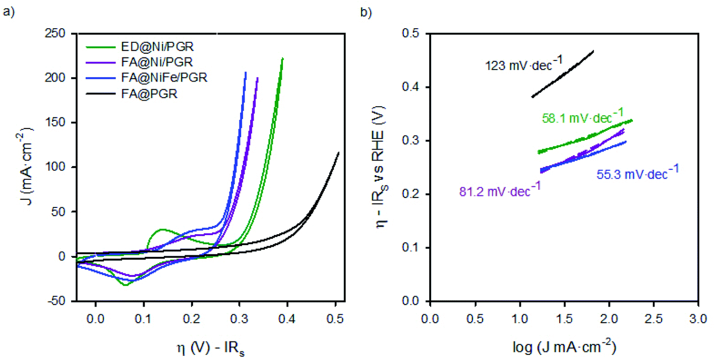 | ||
| Fig. 2 (a) Cyclic voltammograms of FA@PGR, ED@Ni/PGR, FA@Ni/PGR and FA@NiFe/PGR and (b) Tafel Plots of FA@PGR, ED@Ni/PGR, FA@Ni/PGR and FA@NiFe/PGR electrodes measured in KOH 8 M. Scan rate: 25 mV s−1. Tafel plots were obtained from J–V curves under stationary conditions. | ||
The analysis of the FA@PGR sample in Fig. 2a shows a hysteretic behaviour in the flat area of the CV. This capacitive behaviour could be associated with the microporous structure of the rods and the ability of carbon to absorb small cations.30 In the case of the catalyst decorated samples, hysteresis cannot be clearly observed mainly due to the presence of the Ni(OH)2/NiOOH redox peak, which appears preceding the region corresponding to the OER.
The potential at which the Ni2+/Ni3+ redox peak appears, depends on both the Fe content in the catalyst and Ni phase. Specifically, the presence of more than 10% of Fe yields to the a smaller voltage difference between the Ni2+/Ni3+ redox peak and the onset of the OER. By contrast, lower amount of Fe in the Ni electrode separates both phenomena. Thereby, the Ni redox peak is displaced to lower overpotentials while, at the same time, the OER overpotential is higher.13,24 In our case, as can be seen in Fig. 2a, we observe the same trend. Thus, for ED@Ni/PGR with a Ni:Fe ratio of 24:1 (estimated by EDX) the wide redox peak for Ni2+/Ni3+ appears at an overpotential of 0.12 V vs. RHE in the forward direction (0.08 V vs. RHE in the reverse direction) with the onset overpotential for the OER occurring at 0.26 V. However, for FA samples, FA@Ni/PGR and FA@NiFe/PGR with Ni:Fe ratios 9:1 and 3:2, respectively (see Fig. S2 and S3 in the ESI†), both the redox peak and the OER onset are so close such that the two phenomena approach each other and overlap in the CV. From the steady-state J–V curves of the electrodes in Fig. 5d (and Fig. S6d in the ESI†), we could determine with better accuracy both the onset of the OER and, after subtracting the faradaic contribution, the peaks of the overpotentials of the redox states. Thus, for the two FA samples that have Ni:Fe ratios above 9:1, the same values are obtained for the Ni2+/Ni3+ redox peak, ∼0.20 V vs. RHE in the forward direction (and 0.09 V in the reverse direction) and for the onset overpotential for the OER, 0.22 V vs. RHE.
Focusing now on the performance of the electrodes, the interfacial overpotential needed to deliver 10 mA cm2 (of the geometrical area) is ∼270 mV for ED@Ni/PGR and ∼240 mV for FA@NiFe/PG, see Tables 1 and S1.† These values are in line with the ones reported for NiFe deposited onto supporting electrodes made of graphene and exfoliated graphite as reported in Table 1. Furthermore, they improve some of the published values obtained for planar metallic supporting electrodes shown also in Table 1.31,32 Therefore, these materials provide top performance electrodes for the OER while keeping an easy and low-cost processing method. We believe that the performance of our electrodes is due to their high surface area and the interaction between Ni and Fe. As can be seen from the data in Table 1, there is still room to improve the performance of the electrodes, for example minimizing series resistance by including carbon doping to improve its conductivity.
| Catalyst | Electrode support | Electrolyte | H@10 mA cm−2 (mV) | References |
|---|---|---|---|---|
| NiFe | PGR | 8 M KOH | 252 (240) | This work |
| Ni | PGR | 8 M KOH | 290 (270) | This work |
| RuOx | PGR | 1 M KOH | 312 | 9 |
| Ni0.8Fe0.2–AHNA | NiFe NW | 1 M KOH | 180 | 14 |
| NiFe | EG | 1 M KOH | 214 | 31 |
| NiFe | DG | 1 M KOH | 310 | 32 |
| NiFe | Ni foam | 1 M KOH | 240 | 27 |
| NiFe | Pt | 1 M NaOH | 340 | 33 |
| NiFe | GNP | 1 M KOH | 280 | 22 |
| Ni–Ru | RuOx | 0.5 M H2SO4 | 184 | 23 |
| Ru | Pt | 1 M NaOH | 290 | 33 |
Tafel plots in Fig. 2b also showed the increase in the OER catalytic activities of PGR by the addition of the catalysts. In addition to the decrease of the onset potential observed for the decorated samples vs. the bare one, the Tafel slope is reduced ∼60 mV dec−1 when the catalyst is deposited on top of the PGR, which has a slope 120 mV dec−1 when uncoated. Tafel slopes of 60 mV dec−1 have been associated with the proton-coupled electron transfer mechanism for the OER.34
Impedance spectroscopy on Ni and NiFe PGRs
We completed the study of FA@PGR electrodes and the corresponding electrodes decorated with Ni and NiFe (ED@Ni/PGR, FA@Ni/PGR and FA@NiFe/PGR, respectively) by impedance spectroscopy (IS) measurements. In order to determine the electrocatalytic active surface area (ECSA) of PGR during the FA, through IS, we compared the capacitance of glassy carbon and PGR at low voltages (−0.2 V), where neither redox nor faradaic currents were used. The resulting ECSA obtained shows a huge increase in the electrocatalytic active area of around 700 and 1000 times in ED and FA samples, respectively (Table S1†), with these ECSA values being responsible for the improvement in the OER performance achieved by PGR after FA treatment.For a better understanding of the performance of Ni and NiFe on PGR electrodes, IS analysis in the area of the Ni2+/Ni3+ redox peak and the OER onset was performed. Fig. 3 shows the Nyquist and Bode plot data of FA@PGR and FA@NiFe/PGR obtained at overpotentials before and after the OER onset (−0.05 and 0.35 V vs. RHE). The plots obtained for ED@Ni/PGR are omitted here as they have minimum differences with the FA@NiFe/PGR sample. IS shapes are characterized by two features. At high frequencies (Fig. 3b), a 45° line appears which is followed by an arc at medium-low frequencies. This behaviour is described with a transmission line in two different situations: (i) when transport resistance (Rt) of electrons in the porous material is smaller than charge transfer resistance (Rct) towards the solution, the transmission line presents the shape obtained at low potentials (Fig. 3, line black and blue); (ii) in the opposite case, when Rt > Rct, the transmission line has the shape shown at high voltages (Fig. 3, line gray and cyan) which is given by a Gerischer element.35–38
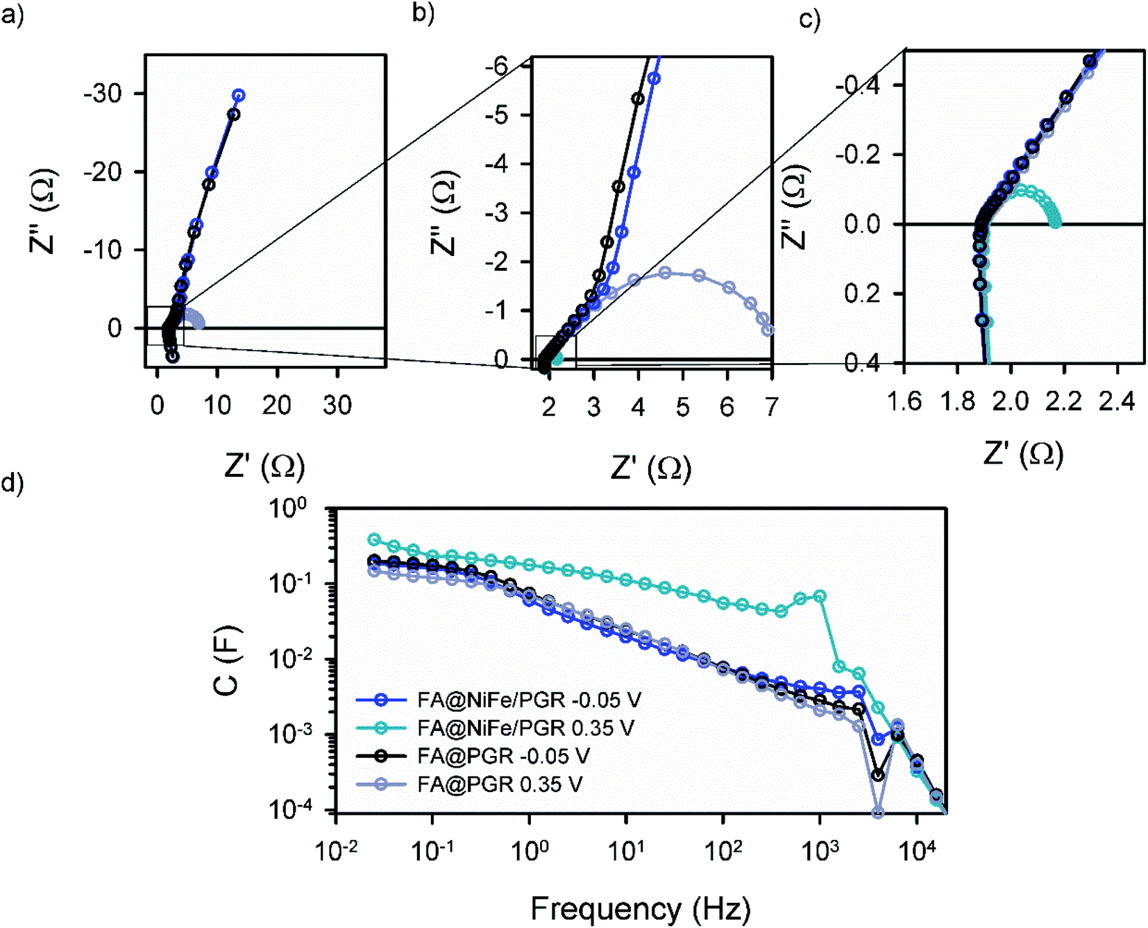 | ||
| Fig. 3 Experimental (a)–(c) NyQuist and (d) ohmic drop corrected Bode plot obtained by impedance spectroscopy of the OER in KOH 8 M using FA@NiFe/PGR and FA@PGR as working electrodes. The dark lines show IS at a low potential (−0.05 V vs. RHE) and the light lines at a high potential (0.35 V vs. RHE). | ||
The first situation is observed at low potentials when there is no current flow to the electrolyte. In this case, Rct is very large (≫Rtr) and the two samples show very similar impedance. When the current flow is activated at higher overpotentials (0.35 V vs. RHE), Rct becomes smaller than Rtr and the arc width (=[RtrRct]1/2) becomes smaller. The incorporation of the catalysts on the PGRs favours the OER performance; this effect is also observed on the IS measurements by the smaller arc in the NiFe case, indicating a better charge transfer (smaller Rct) for the decorated PGRs.
Detailed analysis of IS measurements at overpotentials between −0.2 and 0.4 V vs. RHE was performed by fitting the experimental data with the equivalent circuits (EC) proposed in Fig. 4. The EC suggested for these porous electrodes consists of a transmission line, where electrons are regularly distributed around the PGR (Fig. 4a). However, when the metal catalyst is incorporated into the PGR, the electron conduction occurs along the PGR catalyst line, i.e. where the catalyst is in contact with the PGR. In this new EC (Fig. 4b), a new capacitance is incorporated to describe the OER in the not catalyst covered area.39 The elements employed in these two EC are described as:
 | ||
| Fig. 4 Transmission line based equivalent circuits selected for IS analysis. (a) FA@PGR, (b) ED@Ni/PGR, and FA@NiFe/PGR electrodes. The meaning of the different elements is described in the main text. | ||
• Rs is the series resistance, which includes the resistance of the carbon rod out of the electrolyte together with the resistances of the bulk of the electrolyte and at the contacts.
• rtr is the electron transport resistance per unit length of the PGR electrode immersed in the electrolyte, which yields a total transport resistance Rtr = rtrL.
• rct,G is the charge transfer resistance at the graphite/electrolyte interface. In the case of the ED@Ni/PGR and FA@NiFe/PGR samples, it accounts for the charge transfer at the surface of the PGR which is not coated by the catalyst. At the macroscopic level, the total charge transfer at this interface is given by Rct,G = rct,G/L.
• cG is the capacitance given by the graphite/electrolyte interface. In the case of the decorated samples, it accounts for the uncoated PGR/electrolyte surface. The total capacitance of the graphite is given by CG = cGL.
• rct,cat is the charge transfer resistance associated with Ni or NiFe catalysts. The total contribution to the total charge transfer resistance of the catalyst is given by Rct,cat = rct,cat/L.
• ccat is the capacitance associated with the catalysts (Ni and NiFe) deposited on the PGRs and includes the contribution of their redox states. The total contribution of the catalyst capacitance is given by Ccat = ccatL.
• ZD is the impedance diffusion associated with the reactive species at the diffusion layer in the solution.
With these definitions, the charge transfer resistance and the capacitance of the PGR are given by the parallel combination of the graphite and the catalyst contributions, Rct−1 = Rct,cat−1 + Rct,G−1 and CPGR = Ccat + CG, which are the effective values we measure.
The parameters obtained from the IS fitting are represented as a function of the overpotential (Fig. S6†) and the interfacial overpotential (Fig. 5). Focusing on the capacitance data of the FA@PGR sample (Fig. 5a, black line), a nearly constant capacitance of ∼180 mF cm−2 corresponding to the PGR is observed, with a small peak at an η of 0.35 V, the overvoltage at which charge transfer activates in this sample. We associate this peak with the iron contents of FA@PGR, as a low amount of Fe was detected in this electrode by SEM microanalysis. When we purposely deposited Fe on PGR, the same peak with higher intensity was observed (Fig. S7†). The baseline capacitance observed for ED@Ni/PGR is ∼150 mF cm−2, and for FA@NiFe/PGR is ∼180 mF cm−2, both being attributed to the PGR. The higher Ni coverage of PGR in the ED sample causes a decrease in the PGR capacitance, as indicated in ECSA measurements.
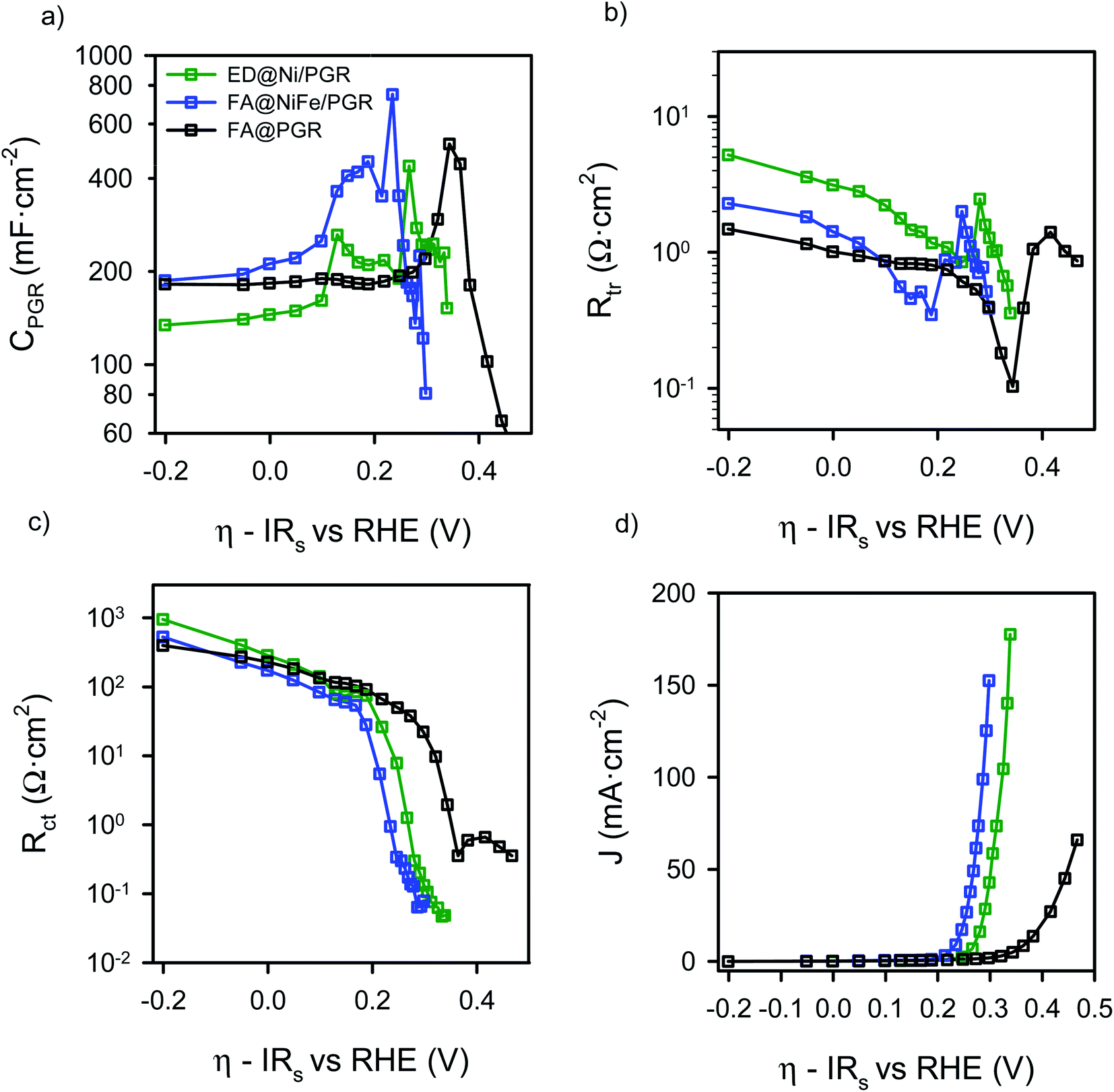 | ||
| Fig. 5 Results from the IS measurements data for FA@PGR (black), ED@Ni/PGR (green) and FA@NiFe/PGR (blue) as a function of the interfacial overpotential (a) electrode capacitance, (b) transport resistance, (c) charge transfer resistance and (d) J–V curve. | ||
When the Ni and NiFe are deposited on the PGR, three capacitance peaks are observed, suggesting a more complex explanation for the peaks observed in the cyclic voltammetry of Fig. 2a. In fact, and according to the literature, the two peaks observed at low overpotentials are attributed to two different Ni2+/Ni3+ redox transitions.40,41 As commented before, the energy of these transitions depends on the Fe content but also to the phase segregation in the sample, which is a function of the deposition environment and the flame annealing treatment.42 There are two possible phases for Ni(OH)2 molecules present at the Ni surface: β-Ni(OH)2, which is the normal and stable phase and the α-phase, a hydrated form of the nickel hydroxide, 3Ni(OH)2·2H2O. The formation of the α-phase is related to the ability of incorporating water between the layers during the nickel deposition on the PGR. We expect that the thermal annealing will yield to a larger proportion of the de-hydrated phase while electrodeposition, which is not thermally treated, will provide a larger amount of the hydrated phase. In any case, α to β conversion phase could happen as a consequence of aging and temperature.43
The oxidation of Ni2+ to Ni3+ by the application of a potential lead to the formation of γ- and β-NiOOH (hydrated and de-hydrated), respectively. According to the literature, α-Ni(OH)2 oxidizes to γ-NiOOH (α/γ) at η = 0.12 V (E0 = 1.35 V vs. RHE) and β-Ni(OH)2 oxidizes to β-NiOOH (β/β) at η = 0.20 V (E0 = 1.43 V vs. RHE),43–46 which match very well with the peaks found in the capacitance of the ED@Ni/PGR electrode in Fig. 5a. This result confirms that the small amount of Fe still present in the ED sample has a minimal effect in the Ni oxidation states, as discussed above. The larger height on the first peak indicates that α/γ transition is the most important one in this sample and dominates the peak in the CV. The β/β transition also occurs, causing the wide peak measured in the CV curve.
The third peak, that appears in Fig. 5a at an overpotential of ∼0.26 V (E0 = 1.49 vs. RHE), corresponds to the redox transformation between Ni3+/Ni4+,43,47,48 which some studies have associated with the formation of NiOO− after deprotonation of NiOOH.12 This peak is strongly affected by the iron concentration of the electrode and marks the starting of the quick decrease of Rct observed in Fig. 5c. Rct is related to the activation of the charge transfer mechanism that yields to the onset of the OER in the CV and the J–V curve in Fig. 2a and 5d, respectively.
For the FA@NiFe/PGR, a clear peak at an overpotential of 0.19 V vs. RHE is observed. We associated this peak to the β/β transitions of Ni2+/Ni3+ which is much larger than in the case of the ED and slightly displaced to more negative potentials. In this case, the data suggest that the α/γ transition contribution to the capacitance is much smaller than in the ED@Ni/PGR case, and only produces a distortion of the Ni2+/Ni3+ peak. Consequently, the peak observed in the CV of Fig. 2 is displaced towards positive values. This result matches well with results obtained in many previous reports.49–51 Therefore, these data suggest that the effect of Fe rather than displacing the Ni3+/Ni2+ peaks is favouring the presence of the β phases of Nickel rather than the α/γ.
For the third peak of the capacitance associated with Ni3+/Ni4+, now we see a reduction in the overpotential needed to make the redox transition to the Ni3+/Ni4+ which now occurs at 0.23 V, see Fig. 5d. Consequently, the OER is activated at an overpotential 30 mV smaller, in good agreement with literature data. Associated with this effect, we can see that the abrupt drop of Rct matches very well with the OER activation in the CV (Fig. 5d). The analysis of Rct shows even more clearly how the onset decrease in Rct is displaced towards smaller overpotentials as we move from the FA@PGR sample to the ED@Ni/PGR and then to the FA@NiFe/PGR, in perfect agreement with the J–V response observed in Fig. 5d.
Non-electrochemical techniques have been used to correlate the detection of the different Ni phase transitions for Ni(OH)2/NiOOH (α/γ and β/β) and the Ni3+/Ni4+ transition with electrochemical techniques.41,45 To the best of our knowledge, the IS analysis performed here has successfully demonstrated for the first time the suitability of this technique for that purpose, showing that IS is a low-cost, easy and useful tool to characterize these kind of samples.
Finally, the transport resistances of FA@NiFe/PGR and FA@PGR present similar values at low voltages, while the ED@Ni/PGR sample presents slightly larger values, see Fig. 5b. This result suggests that larger Fe concentrations produce larger conductivity of the Ni/PGR. Deeper analysis is needed to fully understand this behaviour, which is outside the scope of this paper. At the potentials of the Ni2+/Ni3+ redox transition, Rtr diminishes until a valley is formed, which we associate with the contribution of the redox species to the overall conductivity of the film.
4. Conclusions
We present herein a low-cost procedure to obtain porous Ni-decorated electrodes based on graphite rods which provided a reasonable performance. For the study of their electrochemical response, we designed an impedance model based on a transmission line and made a detailed analysis of the capacitance. This allowed the deconvolution of the contributions of α–γ and β–β phases in the Ni2+/Ni3+ redox transitions. Through this analysis, we could identify the most prominent phases present in each of the electrodes measured here. Thus, we found that in the electrodeposited sample the predominant phases are α-Ni(OH)2 and γ-NiOOH associated with hydrated Ni, while in the case of the sample with flame annealing treatment, the dominant ones are the non-hydrated β phases. Rather than the Fe content, the dominant Ni-phase in the electrode is the origin of the position of the Ni2+/Ni3+ redox peaks found. Finally, we show the direct relationship between the capacitance peak associated with Ni3+/Ni4+ redox transition and the activation of charge transfer resistance and, consequently the oxygen evolution reaction.Author contributions
YK and RA fabricated the samples and performed the measurements; YK and YH performed XPS analysis. RA contributed with cyclic voltammetry and impedance spectroscopy analysis. RT, HM and found the improvement attained by NiFe for flame-annealed catalysts. SI provided the initial idea of the paper, which was completed later by FFS and EMM. FFS made interpretation of impedance spectroscopy data. EMM and FFS directed the experiments and selected the contents for the paper and RA wrote the first version of the paper. All authors revised and improved the paper with their contributions.Conflicts of interest
The authors declare no competing financial interest.Acknowledgements
The authors want to acknowledge the Ministerio de Economía y Competitividad (MINECO) from Spain (ENE2017-85087-C3-1-R), University Jaume I (UJI-B2019-20) and Generalitat Valenciana (PROMETEO/2020/028) for financial support. Serveis Centrals d’Instrumentació Científica from UJI are acknowledged for SEM measurements.References
- D. Gielen, R. Miranda and E. Taibi, Hydrogen: A Renewable Energy Perspective, Japan, 2019 Search PubMed.
- A. Züttel, A. Remhof, A. Borgschulte and O. Friedrichs, Hydrogen: The Future Energy Carrier, Philos. Trans. R. Soc., A, 2010, 368(1923), 3329–3342 CrossRef PubMed.
- M. G. Walter, E. L. Warren, J. R. McKone, S. W. Boettcher, Q. Mi, E. A. Santori and N. S. Lewis, Solar Water Splitting Cells, Chem. Rev., 2010, 110(11), 6446–6473 CrossRef CAS PubMed.
- D. Cardenas-Morcoso, M. García-Tecedor, T. Merdzhanova, V. Smirnov, F. Finger, B. Kaiser, W. Jaegermann and S. Gimenez, An Integrated Photoanode Based on Non-Critical Raw Materials for Robust Solar Water Splitting, Mater. Adv., 2020, 1, 1202–1211 RSC.
- T. R. Cook, D. K. Dogutan, S. Y. Reece, Y. Surendranath, T. S. Teets and D. G. Nocera, Solar Energy Supply and Storage for the Legacy and Nonlegacy Worlds, Chem. Rev., 2010, 110(11), 6474–6502 CrossRef CAS PubMed.
- J. Suntivich, K. J. May, H. A. Gasteiger, J. B. Goodenough and Y. Shao-Horn, A Perovskite Oxide Optimized for Oxygen Evolution Catalysis from Molecular Orbital Principles, Science, 2011, 334(6061), 1383–1385 CrossRef CAS PubMed.
- S. Trasatti, Physical Electrochemistry of Ceramic Oxides, Electrochim. Acta, 1991, 36(2), 225–241 CrossRef CAS.
- Y. Matsumoto and E. Sato, Electrocatalytic Properties of Transition Metal Oxides for Oxygen Evolution Reaction, Mater. Chem. Phys., 1986, 14(5), 397–426 CrossRef CAS.
- R. Tsuji, Y. Koshino, H. Masutani, Y. Haruyama, M. Niibe, S. Suzuki, S. Nakashima, H. Fujisawa and S. Ito, Water Electrolysis Using Thin Pt and RuOx Catalysts Deposited by a Flame-Annealing Method on Pencil-Lead Graphite-Rod Electrodes, ACS Omega, 2020, 5, 6090–6099 CrossRef CAS PubMed.
- European Chemical Society, Element Scarcity, https://www.euchems.eu/euchems-periodic-table/, Accessed May 15, 2020 Search PubMed.
- V. Vij, S. Sultan, A. M. Harzandi, A. Meena, J. N. Tiwari, W.-G. Lee, T. Yoon and K. S. Kim, Nickel-Based Electrocatalysts for Energy-Related Applications: Oxygen Reduction, Oxygen Evolution, and Hydrogen Evolution Reactions, ACS Catal., 2017, 7, 7196–7225 CrossRef CAS.
- O. Diaz-Morales, D. Ferrus-Suspedra and M. T. M. Koper, The Importance of Nickel Oxyhydroxide Deprotonation on Its Activity towards Electrochemical Water Oxidation, Chem. Sci., 2016, 7(4), 2639–2645 RSC.
- D. A. Corrigan, The Catalysis of the Oxygen Evolution Reaction by Iron Impurities in Thin Film Nickel Oxide Electrodes, J. Electrochem. Soc., 1987, 134(2), 377 CrossRef CAS.
- C. Liang, P. Zou, A. Nairan, Y. Zhang, J. Liu, K. Liu, F. Kang, H. J. Fan and C. Yang, Exceptional Performance of Hierarchical Ni–Fe Oxyhydroxide@NiFe Alloy Nanowire Array Electrocatalysts for Large Current Density Water Splitting, Energy Environ. Sci., 2020, 13, 86–95 RSC.
- Y. B. Park, J. H. Kim, Y. J. Jang, J. H. Lee, M. H. Lee, B. J. Lee, D. H. Youn and J. S. Lee, Exfoliated NiFe Layered Double Hydroxide Cocatalyst for Enhanced Photoelectrochemical Water Oxidation with Hematite Photoanode, ChemCatChem, 2019, 11(1), 443–448 CrossRef CAS.
- B. M. Hunter, W. Hieringer, J. R. Winkler, H. B. Gray and A. M. Müller, Effect of Interlayer Anions on [NiFe]-LDH Nanosheet Water Oxidation Activity, Energy Environ. Sci., 2016, 9(5), 1734–1743 RSC.
- J. A. Carrasco, R. Sanchis-Gual, A. S.-D. Silva, G. A. Abellán and E. Coronado, Influence of the Interlayer Space on the Water Oxidation Performance in a Family of Surfactant-Intercalated NiFe-Layered Double Hydroxides, Chem. Mater., 2019, 31, 6807 CrossRef.
- M. Gong, Y. Li, H. Wang, Y. Liang, J. Z. Wu, J. Zhou, J. Wang, T. Regier, F. Wei and H. Dai, An Advanced Ni–Fe Layered Double Hydroxide Electrocatalyst for Water Oxidation, J. Am. Chem. Soc., 2013, 135, 8455 Search PubMed.
- X. Long, J. Li, S. Xiao, K. Yan, Z. Wang, H. Chen and S. Yang, A Strongly Coupled Graphene and FeNi Double Hydroxide Hybrid as an Excellent Electrocatalyst for the Oxygen Evolution Reaction, Angew. Chem., Int. Ed., 2014, 53(29), 7584–7588 CrossRef CAS PubMed.
- D. Tang, J. Liu, X. Wu, R. Liu, X. Han, Y. Han, H. Huang, Y. Liu and Z. Kang, Carbon Quantum Dot/NiFe Layered Double-Hydroxide Composite as a Highly Efficient Electrocatalyst for Water Oxidation, ACS Appl. Mater. Interfaces, 2014, 6, 7918–7925 CrossRef CAS PubMed.
- Z. Lu, W. Xu, W. Zhu, Q. Yang, X. Lei, J. Liu, Y. Li, X. Sun and X. Duan, Three-Dimensional NiFe Layered Double Hydroxide Film for High-Efficiency Oxygen Evolution Reaction, Chem. Commun., 2014, 50, 6479 RSC.
- P. Thangavel, M. Ha, S. Kumaraguru, A. Meena, A. N. Singh, A. M. Harzandi and K. S. Kim, Graphene-Nanoplatelets-Supported NiFe-MOF: High-Efficiency and Ultra-Stable Oxygen Electrodes for Sustained Alkaline Anion Exchange Membrane Water Electrolysis, Energy Environ. Sci., 2020, 13(10), 3447–3458 RSC.
- A. M. Harzandi, S. Shadman, A. S. Nissimagoudar, D. Y. Kim, H. D. Lim, J. H. Lee, M. G. Kim, H. Y. Jeong, Y. Kim and K. S. Kim, Ruthenium Core–Shell Engineering with Nickel Single Atoms for Selective Oxygen Evolution via Nondestructive Mechanism, Adv. Energy Mater., 2021, 11(10), 1–12 Search PubMed.
- L. Trotochaud, S. L. Young, J. K. Ranney and S. W. Boettcher, Nickel-Iron Oxyhydroxide Oxygen-Evolution Electrocatalysts: The Role of Intentional and Incidental Iron Incorporation, J. Am. Chem. Soc., 2014, 136(18), 6744–6753 CrossRef CAS PubMed.
- R. Tsuji, H. Masutani, Y. Haruyama, M. Niibe, S. Suzuki, S. I. Honda, Y. Matsuo, A. Heya, N. Matsuo and S. Ito, Water Electrolysis Using Flame-Annealed Pencil-Graphite Rods, ACS Sustainable Chem. Eng., 2019, 7(6), 5681–5689 CrossRef CAS.
- P. Dubey, N. Kaurav, R. S. Devan, G. S. Okram and Y. K. Kuo, The Effect of Stoichiometry on the Structural, Thermal and Electronic Properties of Thermally Decomposed Nickel Oxide, RSC Adv., 2018, 8(11), 5882–5890 RSC.
- Q. Song, X. Zhai, F. Yu, J. Li, X. Ren, H. Zhang, M. Zhu, B. Dai, G. Ge and J. Zhang, Defect-Rich Nickel Nanoparticles Supported on SiC Derived from Silica Fume with Enhanced Catalytic Performance for CO Methanation, Catalysts, 2019, 9(3), 295 CrossRef.
- K. Wright and A. Barron, Catalyst Residue and Oxygen Species Inhibition of the Formation of Hexahapto-Metal Complexes of Group 6 Metals on Single-Walled Carbon Nanotubes, C, 2017, 3(4), 17 Search PubMed.
- D. Xiong, W. Li and L. Liu, Vertically Aligned Porous Nickel(II) Hydroxide Nanosheets Supported on Carbon Paper with Long-Term Oxygen Evolution Performance, Chem.–Asian J., 2017, 12(5), 543–551 CrossRef CAS PubMed.
- Y. Guo, R. B. Smith, Z. Yu, D. K. Efetov, J. Wang, P. Kim, M. Z. Bazant and L. E. Brus, Li Intercalation into Graphite: Direct Optical Imaging and Cahn-Hilliard Reaction Dynamics, J. Phys. Chem. Lett., 2016, 7(11), 2151–2156 CrossRef CAS PubMed.
- Y. J. Ye, N. Zhang and X. X. Liu, Amorphous NiFe(Oxy)Hydroxide Nanosheet Integrated Partially Exfoliated Graphite Foil for High Efficiency Oxygen Evolution Reaction, J. Mater. Chem. A, 2017, 5(46), 24208–24216 RSC.
- J. Wang, L. Gan, W. Zhang, Y. Peng, H. Yu, Q. Yan, X. Xia and X. Wang, In Situ Formation of Molecular Ni-Fe Active Sites on Heteroatom-Doped Graphene as a Heterogeneous Electrocatalyst toward Oxygen Evolution, Sci. Adv., 2018, 4, 3 Search PubMed.
- C. C. L. McCrory, S. Jung, I. M. Ferrer, S. M. Chatman, J. C. Peters and T. F. Jaramillo, Benchmarking Hydrogen Evolving Reaction and Oxygen Evolving Reaction Electrocatalysts for Solar Water Splitting Devices, J. Am. Chem. Soc., 2015, 137(13), 4347–4357 CrossRef CAS PubMed.
- K. S. Joya, L. Sinatra, L. G. Abdulhalim, C. P. Joshi, M. N. Hedhili, O. M. Bakr and I. Hussain, Atomically Monodisperse Nickel Nanoclusters as Highly Active Electrocatalysts for Water Oxidation, Nanoscale, 2016, 8(18), 9695–9703 RSC.
- S. Gimenez, H. K. Dunn, P. Rodenas, F. Fabregat-Santiago, S. G. Miralles, E. M. Barea, R. Trevisan, A. Guerrero and J. Bisquert, Carrier Density and Interfacial Kinetics of Mesoporous TiO2 in Aqueous Electrolyte Determined by Impedance Spectroscopy, J. Electroanal. Chem., 2012, 668, 119–125 CrossRef CAS.
- F. Fabregat-Santiago, J. Bisquert, G. Garcia-Belmonte, G. Boschloo and A. Hagfeldt, Influence of Electrolyte in Transport and Recombination in Dye-Sensitized Solar Cells Studied by Impedance Spectroscopy, Sol. Energy Mater. Sol. Cells, 2005, 87(1–4), 117–131 CrossRef CAS.
- J. Bisquert, Influence of the Boundaries in the Impedance of Porous Film Electrodes, Phys. Chem. Chem. Phys., 2000, 2, 4185–4192 RSC.
- J. Bisquert, M. Grätzel, Q. Wang and F. Fabregat-Santiago, Three-Channel Transmission Line Impedance Model for Mesoscopic Oxide Electrodes Functionalized with a Conductive Coating, J. Phys. Chem. B, 2006, 110(23), 11284–11290 CrossRef CAS PubMed.
- A. M. Helmenstine,Table of Electrical Resistivity and Conductivity, https://www.thoughtco.com/table-of-electrical-resistivity-conductivity-608499, Accessed Jul 1, 2020 Search PubMed.
- S. Corby, M. G. Tecedor, S. Tengeler, C. Steinert, B. Moss, C. A. Mesa, H. F. Heiba, A. A. Wilson, B. Kaiser and W. Jaegermann, et al., Separating Bulk and Surface Processes in NiOx electrocatalysts for Water Oxidation, Sustainable Energy Fuels, 2020, 4(10), 5024–5030 RSC.
- L. Francàs, S. Corby, S. Selim, D. Lee, C. A. Mesa, R. Godin, E. Pastor, I. E. L. Stephens, K. S. Choi and J. R. Durrant, Spectroelectrochemical Study of Water Oxidation on Nickel and Iron Oxyhydroxide Electrocatalysts, Nat. Commun., 2019, 10(1), 1–10 CrossRef PubMed.
- M. C. Bernard, P. Bernard, M. Keddam, S. Senyarich and H. Takenouti, Characterisation of New Nickel Hydroxides during the Transformation of α Ni(OH)2 to β Ni(OH)2 by Ageing, Electrochim. Acta, 1996, 41(1), 91–93 CrossRef CAS.
- S. Klaus, Y. Cai, M. W. Louie, L. Trotochaud and A. T. Bell, Effects of Fe Electrolyte Impurities on Ni(OH)2/NiOOH Structure and Oxygen Evolution Activity, J. Phys. Chem. C, 2015, 119, 7243–7254 CrossRef CAS.
- K. Juodkazis, J. Juodkazytė, R. Vilkauskaitė and V. Jasulaitienė, Nickel Surface Anodic Oxidation and Electrocatalysis of Oxygen Evolution, J. Solid State Electrochem., 2008, 12(11), 1469–1479 CrossRef CAS.
- B. J. Trześniewski, O. Diaz-Morales, D. A. Vermaas, A. Longo, W. Bras, M. T. M. Koper and W. A. Smith, In Situ Observation of Active Oxygen Species in Fe-Containing Ni-Based Oxygen Evolution Catalysts: The Effect of PH on Electrochemical Activity, J. Am. Chem. Soc., 2015, 137(48), 15112–15121 CrossRef.
- B. S. Yeo and A. T. Bell, In Situ Raman Study of Nickel Oxide and Gold-Supported Nickel Oxide Catalysts for the Electrochemical Evolution of Oxygen, J. Phys. Chem. C, 2012, 116(15), 8394–8400 CrossRef CAS.
- A. G. Marrani, V. Novelli, S. Sheehan, D. P. Dowling and D. Dini, Probing the Redox States at the Surface of Electroactive Nanoporous NiO Thin Films, ACS Appl. Mater. Interfaces, 2014, 6, 8 CrossRef.
- J. Huang, Y. Li, Y. Zhang, G. Rao, C. Wu, Y. Hu, X. Wang, R. Lu, Y. Li and J. Xiong, Identification of Key Reversible Intermediates in Self-Reconstructed Nickel-Based Hybrid Electrocatalysts for Oxygen Evolution, Angew. Chem., Int. Ed., 2019, 58(48), 17458–17464 CrossRef CAS PubMed.
- M. Cappadonia, J. Divisek, T. Von Der Heyden and U. Stimming, Oxygen Evolution Reaction at Nickel Anodes in Concentrated Alkaline Solution, Electrochim. Acta, 1994, 39, 1559–1564 CrossRef CAS.
- M. W. Louie and A. T. Bell, An Investigation of Thin-Film Ni-Fe Oxide Catalysts for the Electrochemical Evolution of Oxygen, J. Am. Chem. Soc., 2013, 135(33), 12329–12337 CrossRef CAS PubMed.
- Y. Zhou and N. López, The Role of Fe Species on NiOOH in Oxygen Evolution Reactions, ACS Catal., 2020, 10(11), 6254–6261 CrossRef CAS.
Footnote |
| † Electronic supplementary information (ESI) available: ECSA data, SEM images, XPS spectra and complementary impedance spectroscopy plots. See DOI: 10.1039/d1se00351h |
| This journal is © The Royal Society of Chemistry 2021 |