
 Open Access Article
 This Open Access Article is licensed under a Creative Commons Attribution-Non Commercial 3.0 Unported Licence
A membrane-less electrolyzer with porous walls for high throughput and pure hydrogen production†
Pooria
Hadikhani
 *a,
S. Mohammad H.
Hashemi
ab,
Steven A.
Schenk
a and
Demetri
Psaltis
a
*a,
S. Mohammad H.
Hashemi
ab,
Steven A.
Schenk
a and
Demetri
Psaltis
a
aOptics Laboratory, École Polytechnique Fédérale de Lausanne (EPFL), Lausanne, Switzerland. E-mail: pooria.hadikhani@epfl.ch
bComputational Science & Engineering Laboratory, ETH Zurich, Zurich, Switzerland
First published on 15th March 2021
Abstract
Membrane-less electrolyzers utilize fluidic forces instead of solid barriers for the separation of electrolysis gas products. These electrolyzers have low ionic resistance, a simple design, and the ability to work with electrolytes at different pH values. However, the interelectrode distance and the flow velocity should be large at high production rates to prevent gas cross over. This is not energetically favorable as the ionic resistance is higher at larger interelectrode distances and the required pumping power increases with the flow velocity. In this work, a new solution is introduced to increase the throughput of electrolyzers without the need for increasing these two parameters. The new microfluidic reactor has three channels separated by porous walls. The electrolyte enters the middle channel and flows into the outer channels through the wall pores. Gas products are being produced in the outer channels. Hydrogen cross over is 0.14% in this electrolyzer at flow rate = 80 mL h−1 and current density (j) = 300 mA cm−2. This cross over is 58 times lower than hydrogen cross over in an equivalent membrane-less electrolyzer with parallel electrodes under the same working conditions. Moreover, the addition of a surfactant to the electrolyte further reduces the hydrogen cross over by 21% and the overpotential by 1.9%. This is due to the positive effects of surfactants on the detachment and coalescence dynamics of bubbles. The addition of the passive additive and implementation of the porous walls result in twice the hydrogen production rate in the new reactor compared to parallel electrode electrolyzers with similar hydrogen cross over.
Introduction
Emission-free renewable energies are being harnessed to substitute energy from polluting sources. However, fluctuations in their availability necessitate innovative solutions to meet energy supply and demand. In this regard, at times of abundant production, the surplus can be stored in the form of hydrogen using water electrolysis as a sustainable process.1,2 High purity hydrogen produced in this manner can be used in fuel cells or engines to produce energy for both mobile and stationary applications. However, the high costs of the necessary infrastructure have slowed down clean H2 deployment.3 Any improvement in the design, efficiency, and throughput of water electrolyzers will positively impact their adoption in the energy sector.The two main water electrolysis methods are alkaline and polymer electrolyte membrane (PEM) processes that are available commercially. Anion exchange membrane electrolyzers (AEM) are at their early commercialization stage while solid oxide electrolyzers (SOE) and membrane-less architectures are in the development and research stage.4–6 Alkaline electrolyzers work with basic electrolytes7 and their inexpensive electrodes are separated by a diaphragm in order to prevent gas cross-contamination.8 Alkaline electrolyzers are the most mature technologies for hydrogen production due to their simple design and inexpensive catalyst materials.8 PEM electrolyzers use a membrane coated with catalysts on both sides.9 This membrane allows proton migration but prevents the gas from cross over.10 PEM electrolyzers can be used at high current densities with very low gas cross over, and in a compact form factor.9 AEM electrolyzers work with alkaline electrolytes and use an anion conductive membrane.11 This technology can reduce the capital cost of electrolyzers due to the usage of non-precious metal electrodes in contrast to PEM systems.12 The stability of the anion conductive membrane is a barrier against the commercialization of AEMs.13,14 SOEs use a solid electrolyte with two porous electrodes on their two sides.15 These electrolyzers have higher efficiencies compared to low-temperature electrolyzers since they are operating at elevated temperatures.16 However, the solid electrolyte and electrodes should be chemically stable under harsh operational conditions.15
All of the discussed electrolyzers use a membrane or a diaphragm to prevent gas cross-contamination. However, a diaphragm or a membrane introduces additional resistance between the electrodes, increases the cost of the electrolyzer, and reduces the lifetime of the device.5,17–19 Membrane-less electrolyzers have been introduced to remove the need for membranes or separators.17 They rely on the fluidic flow,17,20–26 buoyancy forces,27 or surface forces28 for product separation. Removing the membrane simplifies the design of the electrolyzer, reduces the electrolyzer cost, and increases the lifetime and durability of the device.5 Furthermore, a membrane-less electrolyzer is compatible with a wide range of electrolytes at different pH values.17,29 Thus, it can be used for various electrochemical reactions such as water electrolysis for hydrogen production or brine electrolysis for chlorine production without significant modifications in its design.20,30
The membrane-less electrolyzer geometry can be classified based on the electrode configuration into parallel17,20,25,26 and mesh electrodes.21–23,31,32 In the parallel electrode (PE) electrolyzer shown in Fig. 1a, the electrodes are at the two opposites sides of a rectangular channel where the liquid electrolyte is flowing. In addition to the electrolyte, evolved gaseous products are also flowing in between the electrodes towards the end of the channel. The inertial forces33–36 of the liquid flow keep the bubbles at the channel sides to prevent cross over. As the volume fraction of the bubbles increases by moving downstream, the channel length and flow rate should be decided carefully to prevent the formation of excessively large bubbles.
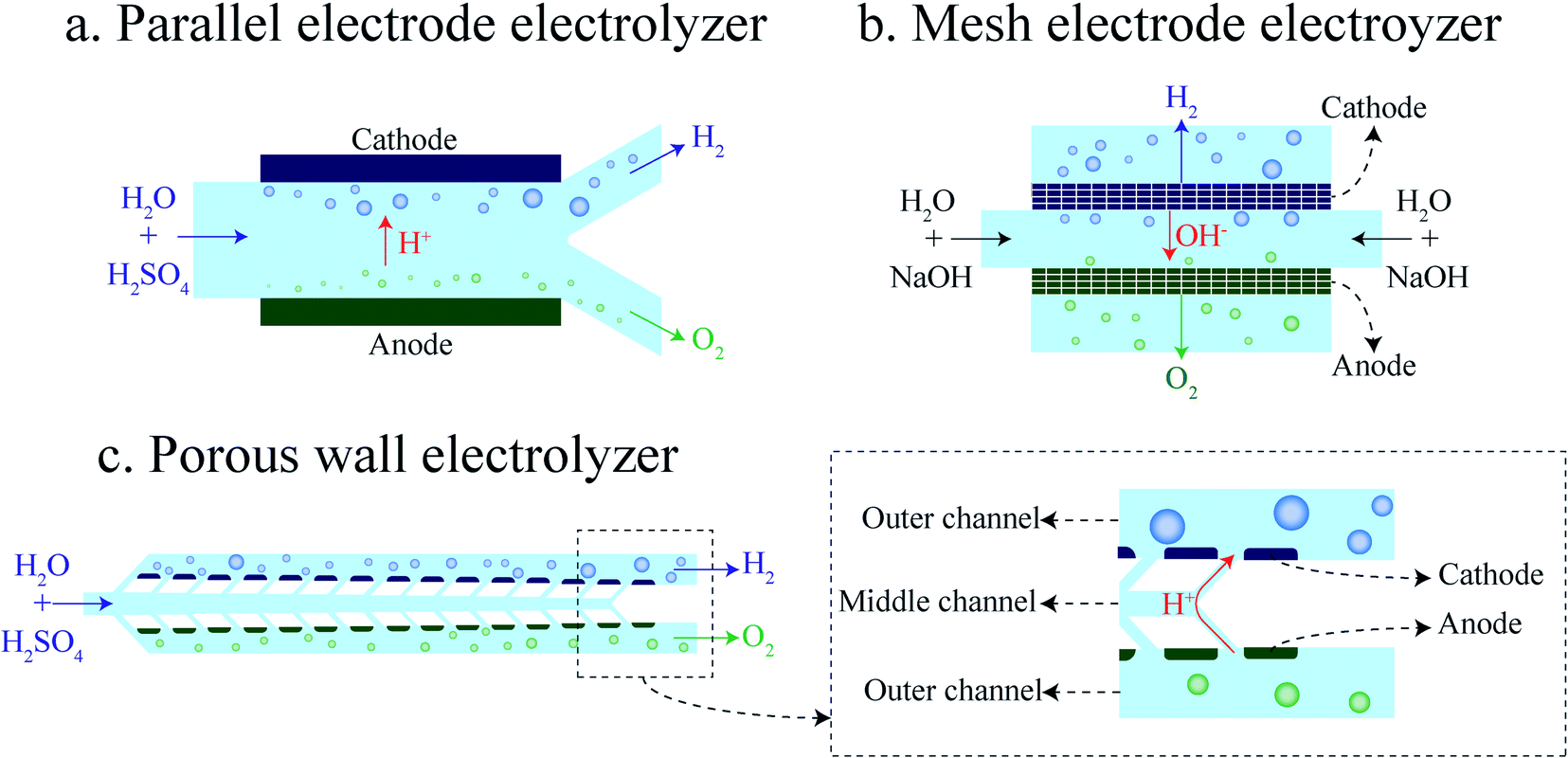 | ||
| Fig. 1 Schematics of membrane-less electrolyzer geometries: (a) parallel electrode electrolyzer, (b) mesh electrode electrolyzer, and (c) porous wall electrolyzer. | ||
The mesh electrode geometry as shown in Fig. 1b is made of two plane meshes that act as catalysts. The liquid enters the area between the meshes and flows through the pores of the mesh. Bubbles are formed at the surface of the mesh and are carried to the outer side of the mesh by the flow. At equal interelectrode distances, the mesh electrode electrolyzer can achieve a higher production rate compared to the PE electrolyzer as the bubbles go through the mesh pores and leave the interelectrode region faster. However, velocities inside all pores of the mesh should be ideally equal for the efficient removal of growing bubbles. Furthermore, the bubbles forming in the inner side of the mesh should remain smaller than the mesh pore size in order to be transported to the outer side.
Product separation is a challenge for membrane-less electrolyzers due to the absence of the membrane or separator. Bubble growth at the electrode and movement in the channel are investigated in order to overcome this challenge.37–42 Bubble coalescence and large bubble detachment from the electrodes can lead to the formation of bubbles larger than half of the channel width which leads to gas cross over. As the large bubbles form more frequently at high production rates the gas cross over is higher at higher production rates.
The addition of a surfactant to the electrolyte decreases the surface tension that leads to smaller bubble detachment.43–46 Furthermore, the surfactant molecules adsorbed on the interface of the bubble prevent bubble coalescence. Therefore, the surfactant can improve the throughput while still having pure streams of products.47 However, the production rate cannot be increased further when the space between the electrodes is filled with bubbles. Enlarging the space between the electrodes leads to a higher maximum production rate, but it imposes additional ohmic losses due to the larger interelectrode gap. Moreover, bubbles moving between electrodes block ionic pathways that add to the overpotential losses.48 Our design is based on the idea that the production rate can be improved by adding pores to the wall of PE electrolyzers for removing bubbles from the interelectrode region faster. However, bubbles larger than the pores cannot go through the pores easily and they flow between the electrodes towards the end of the channel which limits the production rate. To address this limitation and as the second element of our design, we have engineered nucleation sites to be only present outside of the interelectrode region. By doing so, the overpotential due to the bubble movement between electrodes decreases, and the electrode distance can be decreased as well.
In what follows, we design and investigate experimentally and numerically the porous wall (PW) electrolyzer shown in Fig. 1c. In the PW electrolyzer, the liquid electrolyte enters the middle channel and goes to the outer channels through the inclined wall pores. The electrodes are on the outer sides of the porous walls which leads to the generation of bubbles only in the outer channels. The inclined walls and pores ensure sufficient flow in each electrode pore. The flow through the wall pores prevents the migration of bubbles to the opposite side. In this design, the volume fraction of gas in the interelectrode area is low since there is no flow of bubbles in the middle channel. Therefore, the ohmic loss due to the presence of flowing bubbles between the electrodes is smaller compared to that of the parallel electrode design. It is shown that the performance of a PW electrolyzer can be improved further by using a surfactant in the electrolyte.47
The PE electrolyzer geometry is changed to the PW electrolyzer in order to achieve higher production rates. It is essential to compare the product purity and the performance of the PW electrolyzer with those of a PE electrolyzer to evaluate the efficacy of this geometry modification. This comparison demonstrates the effectiveness of the porous walls. As a result, the PW electrolyzer utilizes a smaller flow rate compared to other membrane-less electrolyzers to achieve the cross over comparable to them. This study provides guidelines for the design of membrane-less electrolyzers for achieving high throughput production of hydrogen with high purity.
Experimental setup
The micro-fabrication of the PW electrolyzer starts by depositing 200 nm titanium on a silicon wafer. The electrical connections are made by doing photolithography and metal ion beam etching on the titanium layer. Afterwards, the porous walls supporting vertical electrodes are made using the SU8 process with a height of 70 μm. 200 nm platinum is sputtered on the device followed by ion beam etching.49 The ion beam etching removes platinum from the horizontal surfaces but platinum remains on the vertical walls of SU8. The platinum on the vertical walls is in contact with titanium on the horizontal walls. Subsequently, the fluidic channels are fabricated in SU8. The height of the fluidic channels is 80 μm. The inner sides of the porous walls are covered with SU8 in this step. Therefore, platinum is in contact with the electrolyte only in the outer channels. The inlet and outlets are punched in a PDMS piece. A thin layer of SU8 is coated on this piece. Next, this PDMS piece is bonded to the device to seal the channel.50 Fig. S1 of the ESI† shows the detailed process flow. The minimum interelectrode distance is 550 μm at the end of the electrodes. The maximum interelectrode distance is 690 μm at the beginning of the electrodes. The electrodes active area of the PW electrolyzer is 0.347 mm2. The PE electrolyzer is fabricated with the same process. The interelectrode distance and electrodes active area of the PE electrolyzer are 620 μm and 0.347 mm2. The fabricated PE and PW electrolyzers are shown in Fig. 2.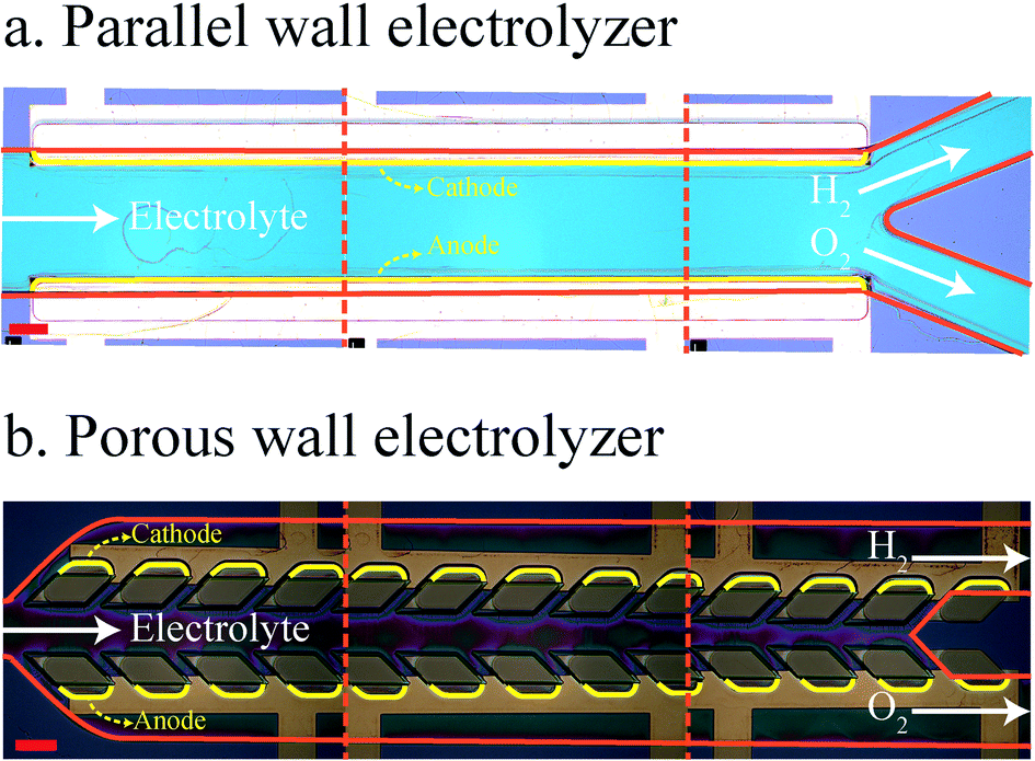 | ||
| Fig. 2 Images of the fabricated PE (a) and PW (b) electrolyzers. Red solid lines indicate the walls. The cathode and anode are indicated by yellow lines. This image is constructed by placing images of three different positions of the device next to each other. The scale bar is 200 μm. | ||
A Cronus Sigma 1000 Series syringe pump is used for flowing electrolytes in the channel. The applied current to the device is controlled using a Bio-Logic SP-300 potentiostat. The images of the bubble generation and flow are captured using a Photron FASTCAM Mini UX100 camera at 4000 fps and 1/10![[thin space (1/6-em)]](https://www.rsc.org/images/entities/char_2009.gif) 000 s shutter speed. Two test tubes are filled with the liquid electrolyte. These test tubes are held inversely in a larger container of the liquid electrolyte. The generated hydrogen and oxygen are collected in these test tubes. The diluted gas with air is injected into the SRI 8610C gas chromatogram with a thermal conductive detector. The current is applied to the device for 15 minutes in each experiment. The experiments are repeated three times at each current density and flow rate.
000 s shutter speed. Two test tubes are filled with the liquid electrolyte. These test tubes are held inversely in a larger container of the liquid electrolyte. The generated hydrogen and oxygen are collected in these test tubes. The diluted gas with air is injected into the SRI 8610C gas chromatogram with a thermal conductive detector. The current is applied to the device for 15 minutes in each experiment. The experiments are repeated three times at each current density and flow rate.
Numerical simulations are carried out using ANSYS Fluent software from ANSYS Inc. Three different types of simulations are used in this paper: 1. Single phase simulations to investigate the velocity profile in the fluidic channels, 2. Mixture model simulations to optimize the geometry of the device for minimizing the gas crossover, 3. Volume of fluid (VOF) simulations to examine the product separation in the optimized geometry under realistic bubble production conditions. The pressure-based solver of ANSYS Fluent is used for the simulations. In the mixture model, the drag coefficient needed to compute the relative velocity51,52 between the phases is calculated using the Schiller and Naumann correlation.53
Results and discussion
Both the PE and the PW electrolyzers shown in Fig. 1a and c are used for hydrogen generation and compared in this study. They have equal electrode surface areas and the interelectrode distance of the PE electrolyzer (620 μm) is equal to the average interelectrode distance of the PW electrolyzer. Initially, we discuss the performance and product purity of the PE electrolyzer, and then present the results of the PW electrolyzer for comparison with those of the PE electrolyzer.PE electrolyzer
Fig. 3a shows bubble generation in the PE electrolyzer at a current density of j = 300 mA cm−2 at different flow rates. The electrolyte is 1 M sulfuric acid. This figure indicates that the liquid flow detaches bubbles at smaller sizes as the flow rate increases. However, the small bubble detachment is not enough to prevent large bubble formation in the channel. The bubble coalescence leads to the formation of large bubbles whose equilibrium positions are at the center of the channel.37 Bubbles moving at the centerline are a mixture of hydrogen and oxygen as they coalesce with bubbles originating from both sides. As a result, large bubbles should be avoided.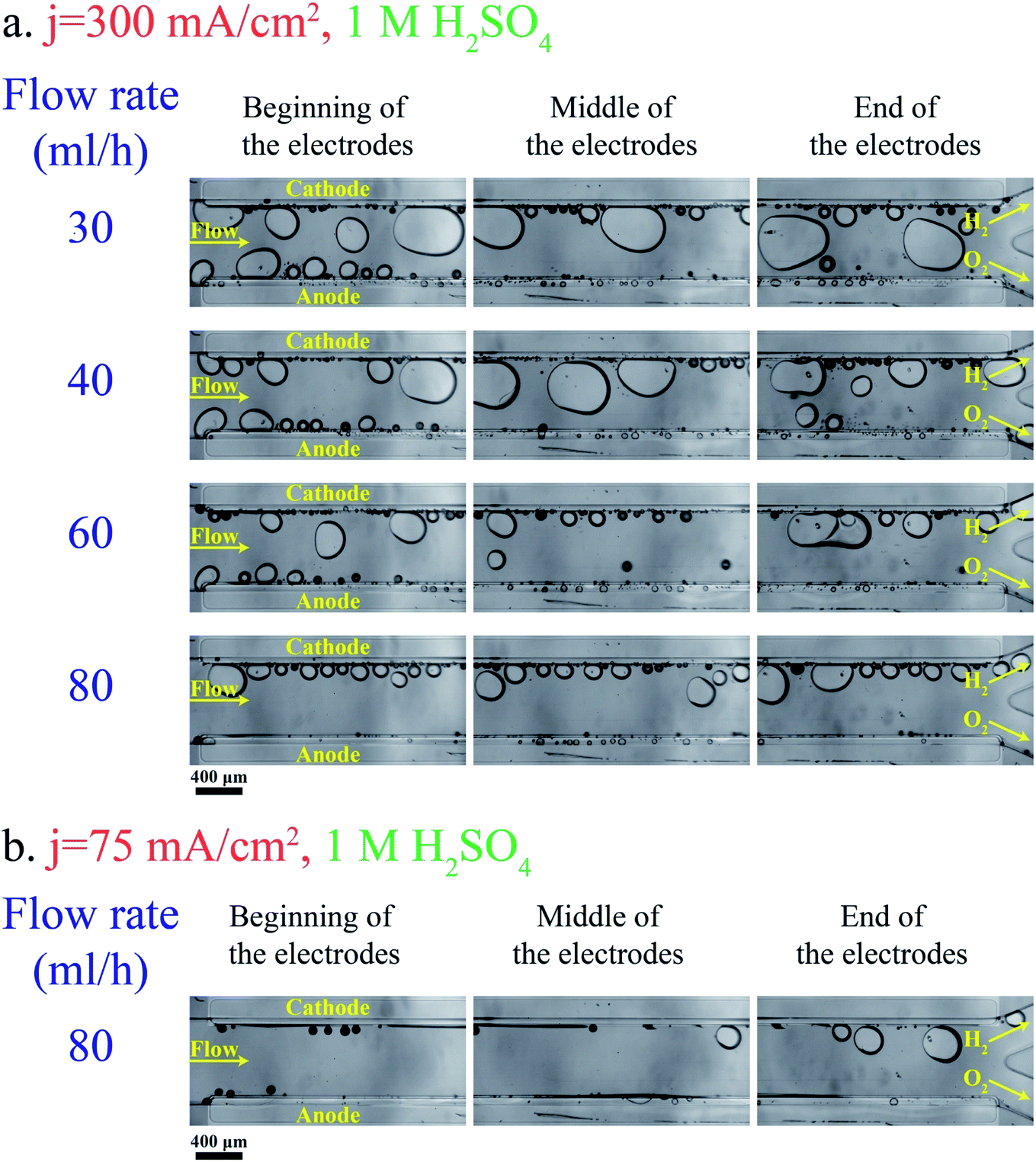 | ||
| Fig. 3 Bubble generation and flow at different locations in the PE electrolyzer working with 1 M H2SO4: (a) the current density is 300 mA cm−2. (b) The current density is 75 mA cm−2. The anode and cathode sides are indicated in the picture. The scale bar is 400 μm. | ||
Decreasing the production rate is one approach to reduce the bubble size and cross over. Fig. 3b presents the bubble flow at flow rate = 80 mL h−1 and j = 75 mA cm−2. This figure depicts the reduction in the bubble size when the current density is decreased from 300 mA cm−2 to 75 mA cm−2. The number of bubbles in the channel decreases with decreasing the current density. Bubble coalescence becomes less frequent at lower current densities, leading to the formation of smaller bubbles and lower cross overs.
As shown in Fig. 3a, the bubble size is inversely proportional to the flow rate. As a result, large bubble formation and gas cross over can be hindered completely at large flow rates. On the other hand, the power loss due to the fluidic resistance is higher at large flow rates which leads to lower energy conversion efficiency. The energy conversion efficiency can be expressed by the following equation:54
 | (1) |
| Pstorage = jLHE0 | (2) |
| Poverpotential = jLH(|ηHER| + ηOER + ηohmic) | (3) |
 | (4) |
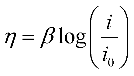
In eqn (4), β, i, and i0 are the Tafel slope, applied current density, and exchange current density, respectively. In the acid, the Tafel slope and the exchange current density of the oxygen evolution reaction on the platinum electrode are 100 mV dec−1 and 4 × 10⁻¹⁰ A cm−2, respectively.55 The Tafel parameters of the hydrogen evolution reaction are β = 32 mV dec−1 and i0 = 1.3 × 10⁻³ A cm−2.24,56 The overpotential due to the electrolyte ohmic resistance is calculated using the following equation:
 | (5) |
| Pfluidic = ΔP × Q | (6) |
The pressure drop of multiphase flows can be written as57
| ΔP = ΔPfriction + ΔPacceleration | (7) |
| L | 4.84 mm |
| H | 80 μm |
| W | 620 μm |
| E 0 | 1.23 V |
| P | 1060 kg m−3 |
| M | 0.001208 kg m−1 s−1 |
| σ (ref. 58) | 36.95 S m−1 |
The power conversion efficiency is a function of two independent variables: the current density and the flow rate. This efficiency can be calculated from eqn (1) by varying the current density and the flow rate independently. The power conversion efficiency is drawn for the PE electrolyzer for different flow rate and current density values in Fig. 4. This figure displays that increasing the flow rate to values higher than 100 leads to approximately more than 55% power loss. As a result, increasing the flow rate to values larger than 100 cannot be considered as a solution for reducing bubble crossover since it induces significant power losses.
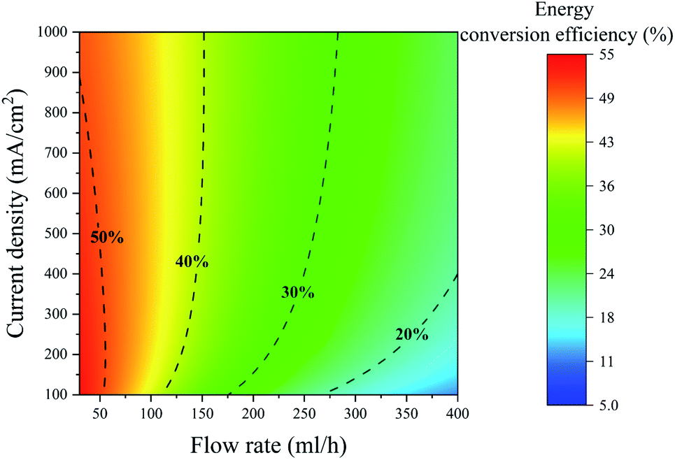 | ||
| Fig. 4 Contour of the energy conversion efficiency of the PE electrolyzer at different current densities and flow rates. The dashed lines indicate the constant energy conversion efficiency lines. The electrolyte is 1 M sulfuric acid. | ||
Fig. 4 shows that the energy conversion efficiency changes non-monotonically with the current at a constant flow rate. At low current densities, the energy conversion efficiency increases by increasing the current density since higher production rates can be achieved without any significant change in the fluidic power loss. However, the efficiency starts to decrease at high current densities. At high current densities, there is a large number of bubbles in the channel that induces a substantial fluidic power loss. This increase in the fluidic power loss leads to a decrease in the energy conversion efficiency. The constant energy conversion efficiency line of 50% in Fig. 4 shows this non-monotonic change of the energy conversion efficiency.
Adding a surfactant to the electrolyte is another solution for reducing the bubble size. Heptadecafluorooctancesulfonic acid potassium (PFOS) is used as the surfactant in this study since it does not participate in the electrochemical reaction and can reduce the overpotential by lowering hydrogen dissolution in the electrolyte.59Fig. 5a shows bubble generation at j = 300 mA cm−2 and different flow rates. This figure shows many bubbles evolving close to each other. But the surfactant in the electrolyte prevents the coalescence of these bubbles. Therefore, the bubbles at the end of the electrodes are smaller compared to those in the surfactant-free electrolyte (Fig. 3a). Fig. 5b shows the images of the PE electrolyzer working at a higher current density of 450 mA cm−2. This figure indicates that the cross over increases significantly by increasing the current density to 450 mA cm−2 and the flow rate is not high enough to prevent bubbles from moving towards the centerline.
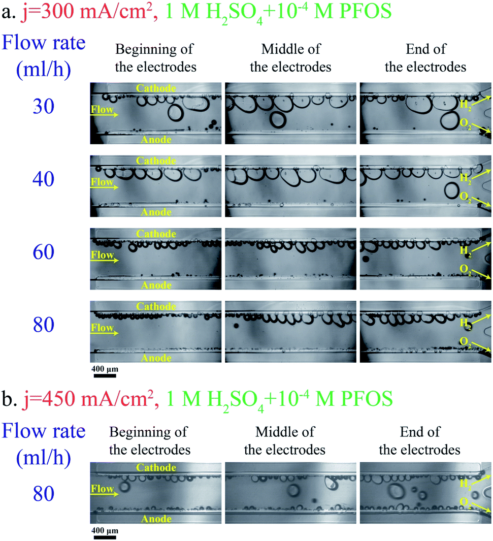 | ||
| Fig. 5 Pictures of different regions of the PE electrolyzer working with 1 M H2SO4 + 10−4 M PFOS surfactant: (a) the applied current density is 300 mA cm−2. (b) The current density is 450 mA cm−2. The hydrogen and oxygen sides are denoted in the pictures. The scale bar is 400 μm. | ||
Fig. 6a shows the polarization curve of the PE electrolyzer. The slope of the polarization curve is steeper when using the electrolyte with the surfactant. This can be attributed to the faster bubble detachment from the electrodes and smaller bubbles flowing in between the electrodes. Furthermore, PFOS reduces the dissolved hydrogen concentration close to the electrode.59 This leads to a lower concentration overpotential due to hydrogen supersaturation at the electrode surface.60 As a result, the required potential for the reactions decreases at constant current densities as shown in Fig. 6a.
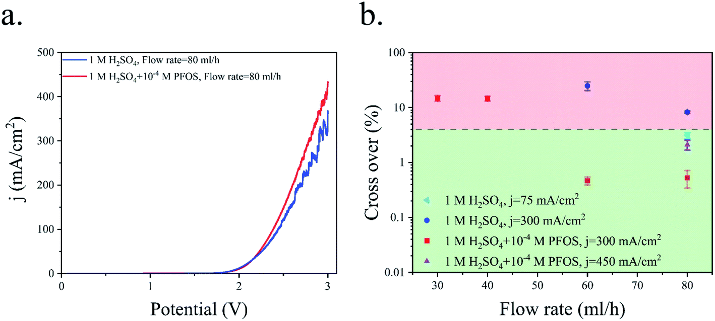 | ||
| Fig. 6 (a) Polarization curve of the PE electrolyzer working with 1 M H2SO4 with and without the PFOS surfactant. The scan rate is 100 mV s−1. (b) Hydrogen cross over to the oxygen side at different Re values. | ||
Fig. 6b presents the hydrogen cross over to the oxygen side for the experiments shown in Fig. 3 and 5. The lower flammability limit of the hydrogen–oxygen mixture is 4%61 and is highlighted by the dashed line in Fig. 6b. The cross over is low at high flow rates because the gas volume fraction is smaller for a constant production rate. However, the cross over is higher than the flammability limit when the surfactant-free electrolyte is used even at high flow rates. The bubble coalescence at flow rates of 30 mL h−1 and 40 mL h−1 creates large bubbles in the hydrogen outlet. Subsequently, these bubbles merge downstream and block the hydrogen outlet. Consequently, the liquid and all the bubbles flow through the oxygen outlet. The hydrogen channel remains blocked until the end of the experiment which creates an enormous hydrogen cross over. Thereby, the hydrogen cross over is not shown in Fig. 6b at flow rates below 40 mL h−1 in the surfactant-free electrolyte. This problem can be resolved by using larger outlet channels but the cross over does not fall below the flammability limit due to large bubble formation inside the electrolyzer. The cross over reduces to below the flammability limit at flow rate = 80 mL h−1 either by adding the surfactant to the electrolyte or decreasing the production rate.
Fig. 6b indicates that hydrogen cross over below 1% can be achieved using the electrolyte with the surfactant and at j = 300 mA cm−2. However, 300 mA cm−2 is the maximum current density beyond which the hydrogen cross over exceeds 1% in the range of flow rates used in this study. As shown in Fig. 4, a further increase in the flow rate leads to lower power conversion efficiencies. As a result, achieving a higher production rate at higher flow rates is not efficient.
The flow of bubbles between the electrodes is the main drawback of the PE electrolyzer. The presence of bubbles between the electrodes has an adverse effect on the effective electrolyte conductivity48,62 since bubbles block ionic pathways. The flowing bubbles can cover the electrode surface when the number of bubbles increases in the channel. This reduction in the electrode active area augments the overpotential and reduces the electrolyzer efficiency. Moreover, the number of bubbles increases from the inlet to the outlet. This change in the volume fraction induces a non-uniform current density along the electrode.63 Increasing the current density in the PE electrolyzer magnifies these adverse effects and reduces significantly the efficiency.
Design of the PW electrolyzer
The PW electrolyzer utilizes two porous walls between nucleation sites that help with product separation. The bubbles cannot go through the wall pores due to the opposite flow direction from the middle channel. Furthermore, the pores require the large bubbles to deform in order to pass through them; a phenomenon that is not energetically favorable. A confined bubble travels in the outer channel rather than the wall pores as it experiences smaller deformation. As a result, this design can efficiently deal with large bubbles, forming at high current densities. However, smaller bubbles can flow through the wall pores and move to the middle channel. This often happens in the presence of reverse flows in the wall pores. Moreover, the ionic resistance between the electrodes is directly proportional to the size and number of the wall pores. Therefore, this design should be optimized to achieve effective product separation while minimizing the ionic resistance.The distance between the electrodes is assumed to be constant and the geometry of porous walls is optimized to achieve a high production rate without any cross over. Two design criteria of the PW electrolyzer are the equal distribution of liquid flow in the wall pores and a negligible gas cross over. Fig. 7a shows four steps of the geometry optimization with the corresponding water volume fraction contours achieved from mixture flow simulations. For each geometry, the conservation of mass and momentum are solved to determine the flow distribution in the wall pores for a single-phase flow. In this simulation, the working fluid is water. Water enters the middle channel at a velocity of 0.4 m s−1 and exits through outlets of the outer channels.
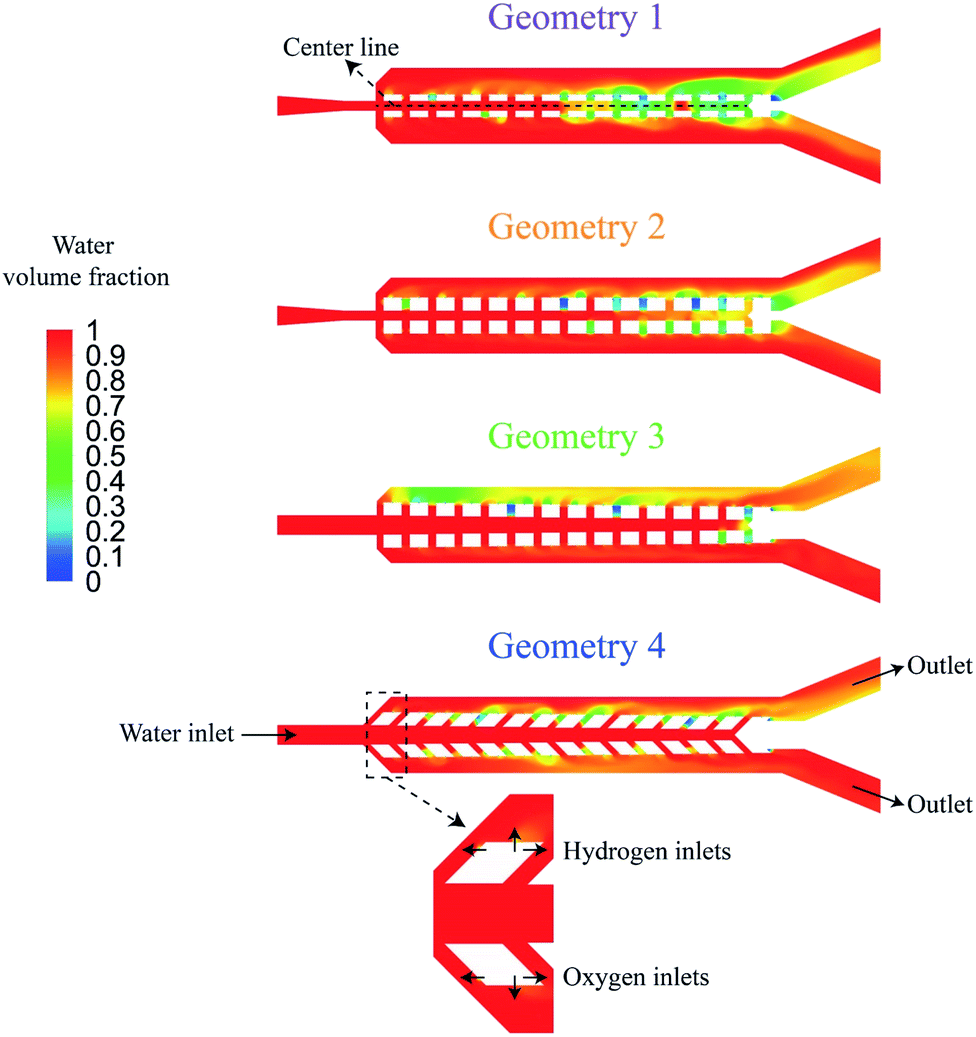 | ||
| Fig. 7 The design and boundary conditions are shown at four steps of geometry optimization. The length of wall pores is 100 μm in geometry 1. The length of wall pores is increased to 200 μm in geometry 2. Afterwards, the porous walls are rotated by 0.75° in geometry 3. Finally, the wall pores are rotated by 45° in geometry 4. The contours are the water volume fraction from mixture flow simulation at t = 0.2 s. The inlet velocity is 0.4 m s−1. | ||
Secondly, mixture equations are solved to estimate the gas cross over in each geometry. The primary phase is water and the secondary phases are hydrogen and oxygen. The water enters from the left port at the velocity of 0.4 m s−1 and exits through the outer channel outlets. Hydrogen and oxygen enter the channel through small inlets on the outer sides of posts at velocities of 0.02 m s−1 and 0.01 m s−1, respectively corresponding to a current density of 1.6 A cm−2. These small inlets are used instead of the total surface of the electrode for the gas inlets in order to imitate the nucleation points. It is assumed that the facing sides of the opposite posts are not active production sites. The boundary conditions are shown in Fig. 7. The surface tension for the hydrogen-water and oxygen-water pairs is considered to be equal to the air–water surface tension which is 0.072 N m−1.37 The surface tension between hydrogen and oxygen is neglected. The average diameter of hydrogen and oxygen bubbles is assumed to be 10 μm. Table 2 presents the density and viscosity of the fluids used in these simulations.
| Fluid | Density (kg m−3) | Viscosity (kg m−1 s−1) |
|---|---|---|
| Water | 998.2 | 0.001003 |
| Hydrogen | 0.08189 | 1.919 × 10⁻⁵ |
| Oxygen | 1.2999 | 8.411 × 10⁻⁶ |
The maximum velocity along the wall pores is presented in Fig. 8a based on the single-phase simulations. Fig. 8b shows the water volume fraction along lines drawn in the middle of the channel based on multi-phase simulations. The water volume fraction is one at the centerline if there is no cross over. Geometry 1 has 100 μm wide pores. The liquid flow velocity is not equal in the pores of this design and the water volume fraction falls below 0.8 in the centerline after 0.4 s. The width of the pores is increased to 200 μm in geometry 2. This change increases the water volume fraction at the centerline but there is more than 10 percent gas in the channel centerline and the flow distribution is not uniform in the pores. To address this issue, the porous walls are rotated by 0.75° in opposite directions to construct geometry 3. In this new geometry, the flow distribution is uniform and the water volume fraction is 0.99. Fig. 7 shows the gas cross over at the end of the middle channel of geometry 3. In the final step, geometry 4 is considered by tilting the wall pores by 45°. The channel centerline remains free of bubbles during 0.5 s simulation after this change as shown in Fig. 8b. This modification completely suppresses the gas cross over and keeps the uniform flow distribution in the wall pores. The effect of the wall pores' angles and sizes is further investigated in Fig. S2 of the ESI.†
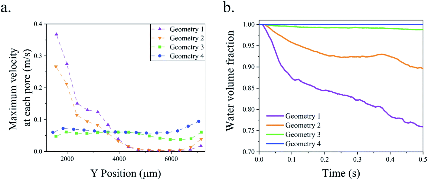 | ||
| Fig. 8 (a) The velocity distribution at wall pores in the single-phase simulations. (b) Average water volume fraction at the channel centerline in the mixture flow simulations. The channel centerline is shown in Fig. 7. | ||
In the water electrolyzer, the bubbles can coalesce and create a larger bubble. The mixture flow simulations shown in Fig. 7 assume small bubble sizes and do not capture the bubble boundaries. Furthermore, these simulations do not consider the effect of bubble interactions, coalescence, and deformation. The multiphase mixture model is suitable for the optimization of the geometry due to its low computational cost, but the optimized geometry should be validated by a more accurate model to consider the effect of large bubbles. The volume of fluid method determines the shape and position of the bubble boundary and can simulate the bubble interaction. This method is used to simulate the gas production and flow in geometry 4. Fig. 9 shows the results of the volume of fluid simulation at three different water inlet velocities. The bubbles block the wall pores when the inlet velocity is 0.05 m s−1 that results in the flow of bubbles from the outer channels to the middle channel and the creation of a large bubble. At inlet velocities = 0.2 m s−1 and 0.4 m s−1, the liquid flow velocity is sufficient to prevent the blockage of the wall pores and achieve complete gaseous product separation. Movie S1† shows the numerical simulation of bubbles flowing in geometry 4. The PW electrolyzer is designed and fabricated based on geometry 4 with the wall pores angle = 45° and wall pore size = 80 μm.
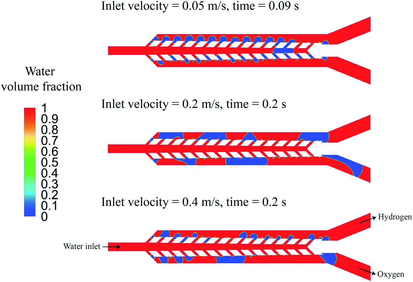 | ||
| Fig. 9 The volume of fluid simulation of geometry 4 at three different inlet velocities 0.05 m s−1, 0.2 m s−1, and 0.4 m s−1. | ||
PW electrolyzer
Fig. 10 shows bubbles generation and flow in the PW electrolyzer at j = 300 mA cm−2 at different flow rate values. In addition to the liquid flow, the porous walls and the controlled bubble production sites (on the outer walls) contribute to product separation. The bubble size is inversely proportional to the flow rate which means that the large bubbles are more frequent at smaller flow rates. The large bubbles flowing in the outer channels do not traverse the wall pores towards the main channel in order to keep their surface energy as low as possible. However, these large bubbles contribute to creating a pressure imbalance between the two outer channels. As a consequence of this imbalance, some smaller bubbles from the outer channels move to the middle channel and even to the opposite outer channel, increasing product cross-contamination. Some of these bubbles can even coalesce in the middle channel and create larger bubbles as observed at the end of the middle channel in Fig. 10. Such large bubbles are trapped in the middle channel and their size decreases from a flow rate of 30 mL h−1 until they completely disappear at flow rate = 80 mL h−1.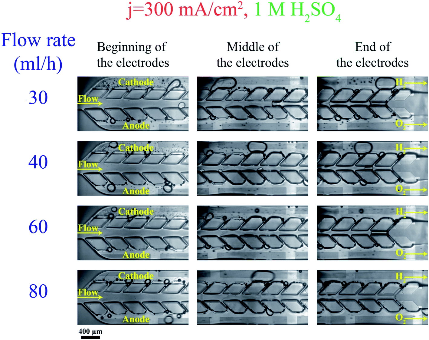 | ||
| Fig. 10 The bubble generation and flow in the PW electrolyzer at j = 300 mA cm−2 and various flow rates: the porous walls keep the hydrogen and oxygen bubbles separated. The cathode and anode sides are specified in the images. The scale bar is 400 μm. | ||
The numerical simulations shown in Fig. 9 predict the large bubble formation in the middle channel at small inlet velocities and the effect of increasing the velocity on removing this bubble. However, the removal of this large bubble from the middle channel happens at smaller velocities in the numerical simulations compared to the experimental results. This difference results from neglecting the effect of the channel height in the two-dimensional simulations.
Bubbles should detach at small sizes from the electrode and their coalescence must be inhibited in order to resolve large bubble formation in the middle channel. Adding surfactants to the electrolyte provides these benefits. The surfactant decreases the bubble size as discussed in the PE electrolyzer section. The bubble generation after adding the PFOS surfactant to the electrolyte is shown in Fig. 11. The above-mentioned pressure imbalance due to the formation of large bubbles decreases and, therefore, bubbles do not migrate to the middle channel and no bubble appears in the middle channel even at low flow rate = 30 mL h−1.
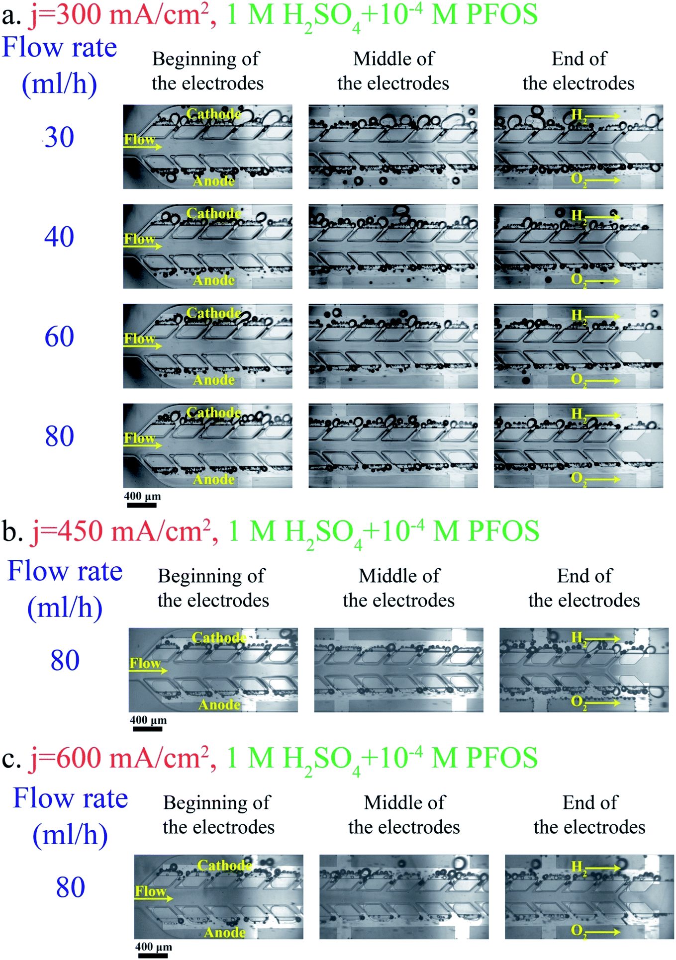 | ||
| Fig. 11 Effect of the PFOS surfactant on bubble generation and flow in the PW electrolyzer working with 1 M H2SO4 + 10−4 M PFOS at j = 300 mA cm−2 (a), 450 mA cm−2 (b), and 600 mA cm−2 (c). The hydrogen and oxygen sides are indicated in the images. The scale bars are 400 μm. | ||
As shown in Fig. 5b, the number of bubbles at the channel centerline of the PE electrolyzer increases significantly by increasing the current density to values higher than 300 mA cm−2. On the other hand, the PW electrolyzer can operate at current densities up to 600 mA cm−2 without detecting any bubble in the middle channel as shown in Fig. 11b and c. The applied potential is 3.03 ± 0.05 V when the PW electrolyzer is working at current density = 450 mA cm−2. The PW electrolyzer requires 3.14 ± 0.06 V when the current density is 600 mA cm−2.
The wall pores are the ionic pathways in the PW electrolyzer. The presence of bubbles in the wall pores blocks the ionic pathways and reduces the effective electrolyte conductivity. A comparison of Fig. 10 and 11 shows that the bubbles are not blocking the wall pores in the electrolyte with the surfactant. Therefore, the available area for the transfer of ions is not reduced. The resulting reduction of the ohmic resistance in the electrolyte with the surfactant compared to that of the surfactant-free electrolyte leads to a better performance of the PW electrolyzer as shown in Fig. 12a.
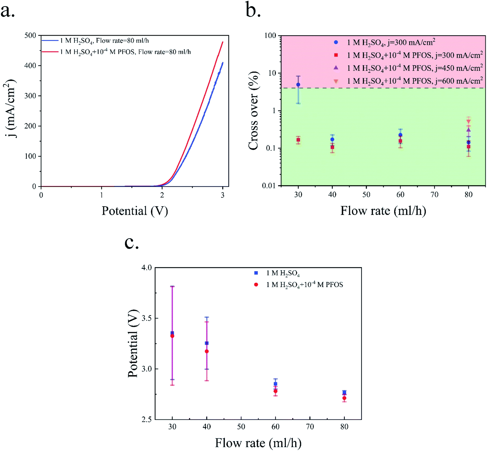 | ||
| Fig. 12 (a) Polarization curve of the PW electrolyzer. The scan rate is 100 mV s−1. (b) Hydrogen cross over to the oxygen side at different flow rates using the electrolyte with and without the surfactant. (c) The working potential at a constant current density of 300 mA cm−2: the bars indicate the standard deviation of the potential in a 4 minute experiment. | ||
The Potentio Electrochemical Impedance Spectroscopy (PEIS) measurements of the PE electrolyzer and the PW electrolyzer are shown in Fig. S3.† This figure indicates that the ohmic resistance between the electrodes is larger in the PW electrolyzer compared to that in the PE electrolyzer. Placing the electrodes in the outer channels and reducing the area normal to ionic pathways are the main reasons for higher electrolyte solution resistance in the PW electrolyzer compared to the PE electrolyzer. On the other hand, the interelectrode space of the PW electrolyzer is free from bubbles while bubbles are flowing between the electrodes in the PE electrolyzer. Accordingly, the overpotential losses due to the flow of bubbles are smaller in the PW electrolyzer compared to those in the PE electrolyzer. The comparison of Fig. 6a and 12a shows that both electrolyzers require approximately the same potential when they work at the same current density. Therefore, the effect of bubble-free ionic pathlength is strong enough to compensate for the lack of generation sites in the sides facing each other in the PW electrolyzer (Fig. 12a) versus the PE electrolyzer (Fig. 6a).
The crossover of hydrogen to the oxygen side in the PW electrolyzer is shown in Fig. 12b. In the surfactant-free electrolyte, the cross over is higher than the flammability limit only when the flow rate = 30 mL h−1. The liquid velocity is not high enough at this flow rate to remove the bubbles from the device before the bubbles become large. The cross over falls below the flammability limit by increasing the flow rate. In the surfactant-free electrolyte, there are bubbles in the middle channel at flow rates = 40 and 60 mL h−1 as shown in Fig. 10b, but these bubbles do not contribute to cross-contamination as they are trapped in the middle channel and cannot go through the wall pores. The addition of PFOS to the electrolyte decreases the cross over further due to the coalescence inhibition and faster bubble detachment which allows for an increase in the current density from 300 mA cm−2 to 600 mA cm−2 while operating in the safe crossover range.
Fig. 12c illustrates the average and standard deviation of the applied potential to the PW electrolyzer at different flow rates and a constant current density of 300 mA cm−2. The bubble residence time on the surface of the electrode decreases as the flow rate increases. There is more available active area if the bubbles leave the electrode surface faster. Consequently, the overpotential due to the electrode surface coverage by bubbles is smaller. Therefore, the applied potential and the potential oscillation decrease by increasing the flow rate.
The hydrogen cross over in the PE and PW electrolyzers is shown in Table 3 which indicates a clear improvement in the cross over by changing the design from the PE electrolyzer to the PW electrolyzer design. The PE electrolyzer can produce products with safe cross overs only at flow rates as high as 80 mL h−1 and using the surfactant. However, the PW electrolyzer achieves a better product separation at a smaller flow rate without using the surfactant. The cross over reduces in both electrolyzers in the electrolyte with the PFOS surfactant. Product separation is still more effective in the PW electrolyzer compared to the PE electrolyzer when PFOS is added to the electrolyte. The maximum current density of the PE and PW electrolyzers is 300 mA cm−2 and 600 mA cm−2 before the cross over exceeds 1% at flow rate = 80 mL h−1. Based on this comparison, the PW electrolyzer achieves two times higher production compared to the PE electrolyzer while the hydrogen cross over remains below 1% and at flow rate = 80 mL h−1.
| Current density (mA cm−2) | Flow rate (mL h−1) | Hydrogen cross over to the oxygen side (%) | |||
|---|---|---|---|---|---|
| PE electrolyzer | PW electrolyzer | ||||
| Electrolyte without PFOS | Electrolyte with PFOS | Electrolyte without PFOS | Electrolyte with PFOS | ||
| 300 | 30 | >50 | 14.7 ± 1.8 | 4.9 ± 3.4 | 0.17 ± 0.04 |
| 300 | 80 | 8.2 ± 0.4 | 0.53 ± 0.19 | 0.14 ± 0.06 | 0.11 ± 0.05 |
| 450 | 80 | — | 2.11 ± 0.43 | — | 0.30 ± 0.09 |
| 600 | 80 | — | — | — | 0.53 ± 0.15 |
It is desired to increase the length of electrodes and the current density in order to achieve higher hydrogen production rates. In the PE electrolyzer, the bubbles are being produced between the electrodes and the gas volume fraction increases continuously along the electrodes. Consequently, increasing the electrode length or the current density results in a large gas volume fraction between the electrodes, lower electrochemical performance, and high pressure drops. On the other hand, the bubbles are flowing in the outer channels of the PW electrolyzer. Increasing the hydrogen production rate or the length will lead to an increase in the gas volume fraction in the outer channels while the middle channel is free from bubbles. Therefore, the bubbles have a smaller effect on the electrochemical reaction in the PW electrolyzer compared to the PE electrolyzer. Furthermore, increasing the width of the outer channels prevents the increase in the pressure drop since the pressure drop is inversely proportional to the cross-sectional area.
The performance of the PW electrolyzer is compared with that of reported membrane-less electrolyzers in Fig. 13. Re is used to represent the velocity of the electrolyte which is calculated using the following equation:
 | (8) |
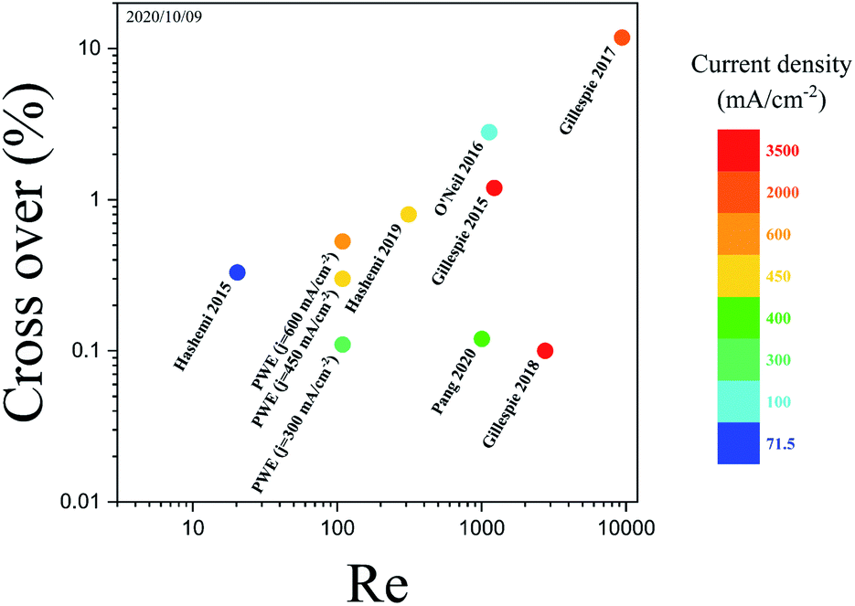 | ||
| Fig. 13 The cross over, Re, and current density of membrane-less electrolyzers.17,20–24,32 The color bar depicts the maximum current density at which the membrane-less electrolyzers are performing water electrolysis. The PW electrolyzer is represented by PWE. The data of the points are presented in Fig. S3 of the ESI.† | ||
The hydrogen cross over in the PW electrolyzer is equal to the smallest reported value but the PW electrolyzer achieves this cross over at smaller Re thanks to its design. Lowering Re reduces the liquid pumping power and increases the energy conversion efficiency.54 PE electrolyzers require high Re in order to prevent large gas volume fraction between the electrodes which leads to bubble cross over. Mesh electrode electrolyzers can operate at smaller Re since the bubbles leave the channel via the closest mesh pore. However, it is difficult to have equal velocity in the mesh pores since they use a uniform mesh size with normal angles. Furthermore, the generation of bubbles between the mesh leads to larger velocity inequality between the mesh pores as the bubbles go through the pores. Therefore, Re should be increased in the mesh electrode electrolyzers to compensate for the unequal velocity distribution. The generation of bubbles in the outer channels and tilting the porous walls and pores in the PW electrolyzer ensure the equal velocity in the wall pores. As a result, the PW electrolyzer requires smaller Re for product separation compared to PE and mesh electrode electrolyzers.
Conclusion
Product separation is a challenging task in membrane-less electrolyzers at high current densities. This paper investigates the effects of geometry modification and the addition of a surfactant to the electrolyte as two strategies in facilitating product separation. The PE electrolyzer achieves good product separation at a low current density of 75 mA cm−2. However, the hydrogen cross over becomes more than the flammability limit at a higher current density of 300 mA cm−2. Bubble coalescence and large bubble detachment are the main reasons for the formation of large bubbles in the channel that leads to unsafe cross-contamination. The addition of the PFOS surfactant to the electrolyte reduces the cross over to the values below the flammability limit as a result of smaller bubble generation and bubble coalescence prevention. Moreover, the PFOS surfactant decreases the surface screening of the electrodes by the bubbles resulting in lower overpotentials.In addition to the surfactant, the design of the membrane-less electrolyzer has a significant role in product separation. The PW electrolyzer is presented to improve the production rate without increasing the cross over. The hydrogen cross over is 58 times smaller in the PW electrolyzer compared to that in the equivalent PE electrolyzer at the current density of 300 mA cm−2. Furthermore, the PW electrolyzer can operate at 50% higher current density compared to the PE electrolyzer with good product separation.
Large-scale membrane-less electrolyzers have a larger interelectrode distance than microfluidic electrolyzers due to the flow of larger bubbles in the scaled-up electrolyzers. The PW electrolyzer design can be scaled-up without increasing the interelectrode distance since there is no bubble flowing between the electrodes. Large scale fabrication of inclined pores and deposition of catalysts only on one side of the pores might be challenging. However, additive manufacturing technologies that have been developed in recent years can be used to facilitate the fabrication of large-scale PW electrolyzers with custom pore designs.64
Conflicts of interest
There are no conflicts of interest to declare.Acknowledgements
This research was supported by the grant no. “CRSII5_173860” of Sinergia for the Multiphase Flow Electrochemical Reactors (MFERS) project (P. H., S. M. H. H., and D. P.) and the grant no. “344091.1 IP-EE” of Innosuisse (S. A. S. and D. P.). The numerical simulations were performed through the use of the facilities of EPFL Scientific IT and Application Support Center.References
- M. Balat, Potential Importance of Hydrogen as a Future Solution to Environmental and Transportation Problems, Int. J. Hydrogen Energy, 2008, 33, 4013 CrossRef CAS.
- Z. P. Cano, D. Banham, S. Ye, A. Hintennach, J. Lu, M. Fowler and Z. Chen, Batteries and Fuel Cells for Emerging Electric Vehicle Markets, Nat. Energy, 2018, 3, 279–289 CrossRef.
- G. Glenk and S. Reichelstein, Economics of Converting Renewable Power to Hydrogen, Nat. Energy, 2019, 4, 216 CrossRef CAS.
- A. Ursúa, L. M. Gandía and P. Sanchis, Hydrogen Production from Water Electrolysis: Current Status and Future Trends, Proc. IEEE, 2012, 100, 410–426 Search PubMed.
- D. V. Esposito, Membraneless Electrolyzers for Low-Cost Hydrogen Production in a Renewable Energy Future Joule, 2017, 1(4), 651–658 CAS.
- P. M. D. Bessarabov, PEM Water Electrolysis, 2018, vol. 1 Search PubMed.
- M. Bodner, A. Hofer and V. Hacker, H2 Generation from Alkaline Electrolyzer, Wiley Interdiscip. Rev.: Energy Environ., 2015, 4, 365 CAS.
- M. David, C. Ocampo-Martínez and R. Sánchez-Peña, Advances in Alkaline Water Electrolyzers: A Review, J. of Energy Storage, 2019, 23, 392–403 CrossRef.
- M. Carmo, D. L. Fritz, J. Mergel and D. Stolten, A Comprehensive Review on PEM Water Electrolysis, Int. J. Hydrogen Energy, 2013, 38(12), 4901–4934 CrossRef CAS.
- C. Xiang, K. M. Papadantonakis and N. S. Lewis, Principles and Implementations of Electrolysis Systems for Water Splitting, Mater. Horiz., 2016, 3, 169 RSC.
- I. Vincent and D. Bessarabov, Low Cost Hydrogen Production by Anion Exchange Membrane Electrolysis: A Review, Renewable Sustainable Energy Rev., 2018, 81, 1690–1704 CAS.
- K. E. Ayers, E. B. Anderson, C. B. Capuano, M. Niedzwiecki, M. A. Hickner, C.-Y. Wang, Y. Leng and W. Zhao, Characterization of Anion Exchange Membrane Technology for Low Cost Electrolysis, ECS Trans., 2013, 45, 121 CrossRef.
- S. Gottesfeld, D. R. Dekel, M. Page, C. Bae, Y. Yan, P. Zelenay and Y. S. Kim, Anion Exchange Membrane Fuel Cells: Current Status and Remaining Challenges, J. Power Sources, 2018, 375, 170 CrossRef CAS.
- K. F. L. Hagesteijn, S. Jiang and B. P. Ladewig, A Review of the Synthesis and Characterization of Anion Exchange Membranes, J. Mater. Sci., 2018, 53, 11131–11150 CrossRef CAS.
- M. Ni, M. K. H. Leung and D. Y. C. Leung, Technological Development of Hydrogen Production by Solid Oxide Electrolyzer Cell (SOEC), Int. J. Hydrogen Energy, 2008, 33(9), 2337–2354 CrossRef CAS.
- A. Mohammadi and M. Mehrpooya, Techno-Economic Analysis of Hydrogen Production by Solid Oxide Electrolyzer Coupled with Dish Collector, Energy Convers. Manage., 2018, 173, 167 CrossRef CAS.
- S. M. H. Hashemi, M. A. Modestino and D. Psaltis, A Membrane-Less Electrolyzer for Hydrogen Production across the PH Scale, Energy Environ. Sci., 2015, 8, 2003 RSC.
- E. Kjeang, R. Michel, D. A. Harrington, N. Djilali and D. Sinton, A Microfluidic Fuel Cell with Flow-through Porous Electrodes, J. Am. Chem. Soc., 2008, 130, 4000 CrossRef CAS PubMed.
- E. Kjeang, N. Djilali and D. Sinton, Microfluidic Fuel Cells: A Review, J. Power Sources, 2009, 186(2), 353–369 CrossRef CAS.
- S. M. H. Hashemi, P. Karnakov, P. Hadikhani, E. Chinello, S. Litvinov, C. Moser, P. Koumoutsakos and D. Psaltis, A Versatile and Membrane-Less Electrochemical Reactor for the Electrolysis of Water and Brine, Energy Environ. Sci., 2019, 12, 1592 RSC.
- M. I. Gillespie and R. J. Kriek, Hydrogen Production from a Rectangular Horizontal Filter Press Divergent Electrode-Flow-Through (DEFT™) Alkaline Electrolysis Stack, J. Power Sources, 2017, 372, 252 CrossRef CAS.
- M. I. Gillespie and R. J. Kriek, Scalable Hydrogen Production from a Mono-Circular Filter Press Divergent Electrode-Flow-Through Alkaline Electrolysis Stack, J. Power Sources, 2018, 397, 204 CrossRef CAS.
- G. D. O'Neil, C. D. Christian, D. E. Brown and D. V. Esposito, Hydrogen Production with a Simple and Scalable Membraneless Electrolyzer, J. Electrochem. Soc., 2016, 163, F3012 CrossRef.
- X. Pang, J. T. Davis, A. D. Harvey and D. V. Esposito, Framework for Evaluating the Performance Limits of Membraneless Electrolyzers, Energy Environ. Sci., 2020, 13, 3663 RSC.
- M. M. Monroe, P. Lobaccaro, Y. Lum and J. W. Ager, Membraneless Laminar Flow Cell for Electrocatalytic CO2 Reduction with Liquid Product Separation, J. Phys. D: Appl. Phys., 2017, 50, 154006 CrossRef.
- I. Holmes-Gentle, F. Hoffmann, C. A. Mesa and K. Hellgardt, Membrane-Less Photoelectrochemical Cells: Product Separation by Hydrodynamic Control, Sustainable Energy Fuels, 2017, 1, 1184 RSC.
- J. T. Davis, J. Qi, X. Fan, J. C. Bui and D. V. Esposito, Floating Membraneless PV-Electrolyzer Based on Buoyancy-Driven Product Separation, Int. J. Hydrogen Energy, 2018, 43, 1224 CrossRef CAS.
- Z. Long, Y. Zhao, C. Zhang, Y. Zhang, C. Yu, Y. Wu, J. Ma, M. Cao and L. Jiang, A Multi-Bioinspired Dual-Gradient Electrode for Microbubble Manipulation toward Controllable Water Splitting, Adv. Mater., 2020, 32, 1908099 CrossRef CAS PubMed.
- B. S. De, A. Singh, A. Elias, N. Khare and S. Basu, An Electrochemical Neutralization Energy-Assisted Membrane-Less Microfluidic Reactor for Water Electrolysis, Sustainable Energy Fuels, 2020, 4, 6234 RSC.
- O. O. Talabi, A. E. Dorfi, G. D. O'Neil and D. V. Esposito, Membraneless Electrolyzers for the Simultaneous Production of Acid and Base, Chem. Commun., 2017, 53, 8006 RSC.
- J. Hartvigsen, J. Smith and F. Dogan, New Low to Medium Temperature Electrolyte Separation Method and System for Alkaline Water Electrolysis, ECS Trans., 2015, 68, 133 CrossRef CAS.
- M. I. Gillespie, F. Van Der Merwe and R. J. Kriek, Performance Evaluation of a Membraneless Divergent Electrode-Flow-through (DEFT) Alkaline Electrolyser Based on Optimisation of Electrolytic Flow and Electrode Gap, J. Power Sources, 2015, 293, 228 CrossRef CAS.
- D. Di Carlo, Inertial Microfluidics, Lab Chip, 2009, 3038–3046 RSC.
- H. Amini, W. Lee and D. Di Carlo, Inertial Microfluidic Physics, Lab Chip, 2014, 2739–2761 RSC.
- Y. Gou, Y. Jia, P. Wang and C. Sun, Progress of Inertial Microfluidics in Principle and Application, Sensors, 2018, 18, 1762 CrossRef PubMed.
- J. Zhang, S. Yan, D. Yuan, G. Alici, N. T. Nguyen, M. Ebrahimi Warkiani and W. Li, Fundamentals and Applications of Inertial Microfluidics: A Review, Lab Chip, 2016, 10–34 RSC.
- P. Hadikhani, S. M. H. Hashemi, G. Balestra, L. Zhu, M. A. Modestino, F. Gallaire and D. Psaltis, Inertial Manipulation of Bubbles in Rectangular Microfluidic Channels, Lab Chip, 2018, 18, 1035 RSC.
- J. T. Davis, D. E. Brown, X. Pang and D. V. Esposito, High Speed Video Investigation of Bubble Dynamics and Current Density Distributions in Membraneless Electrolyzers, J. Electrochem. Soc., 2019, 166, F312 CrossRef CAS.
- Y. Li, G. Yang, S. Yu, Z. Kang, J. Mo, B. Han, D. A. Talley and F. Y. Zhang, In-Situ Investigation and Modeling of Electrochemical Reactions with Simultaneous Oxygen and Hydrogen Microbubble Evolutions in Water Electrolysis, Int. J. Hydrogen Energy, 2019, 44, 28283 CrossRef CAS.
- T. F. Groß, J. Bauer, G. Ludwig, D. Fernandez Rivas and P. F. Pelz, Bubble Nucleation from Micro-Crevices in a Shear Flow: Experimental Determination of Nucleation Rates and Surface Nuclei Growth, Exp. Fluids, 2018, 59, 12 CrossRef.
- P. Van Der Linde, P. Peñas-López, Á. Moreno Soto, D. Van Der Meer, D. Lohse, H. Gardeniers and D. Fernández Rivas, Gas Bubble Evolution on Microstructured Silicon Substrates, Energy Environ. Sci., 2018, 11, 3452 RSC.
- X. Zhao, H. Ren and L. Luo, Gas Bubbles in Electrochemical Gas Evolution Reactions, Langmuir, 2019, 35, 5392 CrossRef CAS PubMed.
- O. Khaselev and J. A. Turner, A Monolithic Photovoltaic-Photoelectrochemical Device for Hydrogen Production via Water Splitting, Science, 1998, 280, 425 CrossRef CAS PubMed.
- R. Babu and M. K. Das, Effects of Surface-Active Agents on Bubble Growth and Detachment from Submerged Orifice, Chem. Eng. Sci., 2018, 179, 172 CrossRef CAS.
- H. Y. Lee, C. Barber and A. R. Minerick, Improving Electrokinetic Microdevice Stability by Controlling Electrolysis Bubbles, Electrophoresis, 2014, 35, 1782 CrossRef CAS PubMed.
- D. Fernández, P. Maurer, M. Martine, J. M. D. Coey and M. E. Möbius, Bubble Formation at a Gas-Evolving Microelectrode, Langmuir, 2014, 30, 13065 CrossRef PubMed.
- P. Hadikhani, S. M. H. Hashemi and D. Psaltis, The Impact of Surfactants on the Inertial Separation of Bubbles in Microfluidic Electrolyzers, J. Electrochem. Soc., 2020, 167, 134504 CrossRef CAS.
- A. Angulo, P. van der Linde, H. Gardeniers, M. Modestino and D. Fernández Rivas, Influence of Bubbles on the Energy Conversion Efficiency of Electrochemical Reactors, Joule, 2020, 555–579 Search PubMed.
- S. C. Kilchenmann, E. Rollo, P. Maoddi and C. Guiducci, Metal-Coated SU-8 Structures for High-Density 3-D Microelectrode Arrays, J. Microelectromech. Syst., 2016, 25, 425 Search PubMed.
- L. Wang, L. Flanagan and A. P. Lee, Side-Wall Vertical Electrodes for Lateral Field Microfluidic Applications, J. Microelectromech. Syst., 2007, 16, 454 CAS.
- Q. H. Mazumder, CFD Analysis of the Effect of Elbow Radius on Pressure Drop in Multiphase Flow, Model. Simul. Eng., 2012, 2012, 125405 Search PubMed.
- M. Manninen, V. Taivassalo and S. Kallio, On the Mixture Model for Multiphase Flow, Finland, 1996 Search PubMed.
- L. Schiller, A Drag Coefficient Correlation, Z. Ver. Dtsch. Ing., 1933, 77, 318–320 Search PubMed.
- M. A. Modestino, D. Fernandez Rivas, S. M. H. Hashemi, J. G. E. Gardeniers and D. Psaltis, The Potential for Microfluidics in Electrochemical Energy Systems, Energy Environ. Sci., 2016, 9, 3381 RSC.
- A. Damjanovic, A. Dey and J. O. M. Bockris, Kinetics of Oxygen Evolution and Dissolution on Platinum Electrodes, Electrochim. Acta, 1966, 11, 791 CrossRef CAS.
- H. Kita, S. Ye and Y. Gao, Mass Transfer Effect in Hydrogen Evolution Reaction on Pt Single-Crystal Electrodes in Acid Solution, J. Electroanal. Chem., 1992, 334, 351 CrossRef CAS.
- G. Yadigaroglu and F. Hewitt, Introduction to Multiphase Flow, Springer International Publishing, 2018 Search PubMed.
- H. E. Darling, Conductivity of Sulfuric Acid Solutions, UTC, 1964 Search PubMed.
- X. Zhao, R. Ranaweera and L. Luo, Highly Efficient Hydrogen Evolution of Platinum: Via Tuning the Interfacial Dissolved-Gas Concentration, Chem. Commun., 2019, 55, 1378 RSC.
- J. Dukovic and C. W. Tobias, Influence Of Attached Bubbles On Potential Drop And Current Distribution At Gas-Evolving Electrodes, in Proceedings - The Electrochemical Society, Electrochemical Soc, 1986, vol. 86–12, pp. 122–147 Search PubMed.
- H. Miao, L. Lu and Z. Huang, Flammability Limits of Hydrogen-Enriched Natural Gas, Int. J. Hydrogen Energy, 2011, 36, 6937 CrossRef CAS.
- M. Philippe, H. Jérôme, B. Sebastien and P. Gérard, Modelling and Calculation of the Current Density Distribution Evolution at Vertical Gas-Evolving Electrodes, Electrochim. Acta, 2005, 51, 1140 CrossRef CAS.
- R. J. Balzer and H. Vogt, Effect of Electrolyte Flow on the Bubble Coverage of Vertical Gas-Evolving Electrodes, J. Electrochem. Soc., 2003, 150, E11 CrossRef CAS.
- S. M. H. Hashemi, U. Babic, P. Hadikhani and D. Psaltis, The Potentials of Additive Manufacturing for Mass Production of Electrochemical Energy Systems, Curr. Opin. Electrochem., 2020, 20, 54–59 CrossRef CAS.
Footnote |
| † Electronic supplementary information (ESI) available. See DOI: 10.1039/d1se00255d |
| This journal is © The Royal Society of Chemistry 2021 |