
 Open Access Article
 This Open Access Article is licensed under a
 Creative Commons Attribution 3.0 Unported Licence
Simulation of bi-layer cathode materials with experimentally validated parameters to improve ion diffusion and discharge capacity†
Ridwanur
Chowdhury
 a,
Aayan
Banerjee
*ab,
Yan
Zhao
c,
Xinhua
Liu
d and
Nigel
Brandon
a
a,
Aayan
Banerjee
*ab,
Yan
Zhao
c,
Xinhua
Liu
d and
Nigel
Brandon
a
aDepartment of Earth Science and Engineering, Imperial College London, UK
bCatalytic Processes and Materials, Faculty of Science and Technology, University of Twente, Netherlands. E-mail: a.banerjee@utwente.nl
cDepartment of Mechanical Engineering, Imperial College London, UK
dSchool of Transportation Science and Engineering, Beihang University, China
First published on 25th January 2021
Abstract
The prospect of thick graded electrodes for both higher energy and higher-power densities in lithium-ion batteries is investigated. The simulation results discussed in previous reports on next-generation graded electrodes do not recognize the effect of material processing conditions on microstructural, transport and kinetic parameters. Hence, in this work, we focus on the effect of material processing conditions on particle morphology and its subsequent influence on microstructure (porosity and tortuosity), along with the resultant transport (solid-phase diffusivity) and kinetic (reaction rate constant) properties of synthesized single-layer cathodes. These experimental insights are employed to simulate the benefits of 400 μm thick bi-layer graded cathodes with two different particle sizes and porosities in each layer. The microstructural, transport, and kinetic information are obtained through 3D imaging and electrochemical impedance spectroscopy (EIS) techniques. These parameters are used to develop bi-layer numerical models to understand transport phenomena and to predict cell performance with such graded structures. Simulation results highlight that bi-layer cathodes display higher electrode utilization (solid phase lithiation) next to the current-collector compared to conventional monolayer cathodes with an increase of 39.2% in first discharge capacity at 2C. Additionally, the simulations indicate that an improvement of 47.7% in energy density, alongside a marginal increase of 0.6% in power density, can be achieved at 4C by structuring the porosity in the layer next to the separator to be higher than the porosity in the layer next to the current-collector.
1. Introduction
The need for the development of secondary lithium-ion batteries (LIBs) with both high power and high energy density is imperative for the advancement of portable devices, electric vehicles (EV), and integrated renewable energy systems. In LIB cell designs, there is an inherent trade-off between power and energy density. Thick electrodes are attractive for high-energy LIB applications because of their potential capability to store high amounts of Li+ with increasing amounts of active materials (AM). However, as the electrode thickness increases, mass transport limitations in both solid and liquid phase become more important impeding the power delivery.1–5 Previous studies have revealed that underutilization of the AM near the current collector (CC) at high C-rates is one of the main reasons for power fade in thick electrodes (≥174 μm).6,7 This electrode underutilization can be attributed to Li+ depletion in the liquid phase and/or a Li+ diffusion gradient in the solid-phase.6A promising thick electrode design investigated by researchers is the graded electrode, where porosities and particle sizes are spatially varied to improve cell performance.8–13 In this article, performance is defined in terms of the usable energy and/or power density during discharge (lithiation) of the cell. The rationale behind such an electrode design approach includes: (i) allowing larger amount of Li+ transport in the liquid phase near the current collector through increased porosity in that region of the electrode, and (ii) increasing the local rate of Li+ uptake through the use of small particles with reduced diffusion lengths. Ramadesigan et al. simulated a graded LiCoO2 cathode, where the porosity profile was divided equally into 5 layers, with constant porosity within each layer.8 The porosity was decreased in each layer towards the direction of the current collector. They reported that a 15–33% decrease in ohmic resistance in the liquid phase was possible compared to an overall constant porosity design, which in turn increased the deliverable energy. Dai and Srinivasan revisited the idea of using such graded electrodes to achieve better energy density.9 They simulated a Li2Mn2O4 cathode structure with similar arrangement as ref. 8 at different C-rates (0.1C–3C), where the porosity was decreased from 60% to 15% towards the current collector. They concluded that no significant improvement in the liquid phase polarization, in the solid phase concentration, or in the energy density was observed by using a graded porosity electrode compared to an optimized constant porosity design from their simulation. They went even further, concluding that considering the manufacturing challenges associated with varying porosities, the use of such a gradient-based porous structure is not warranted. Du et al. also investigated several continuously changing porosity profiles and determined that grading the electrode design only resulted in a relatively small increase in performance,6 over the range of conditions evaluated. Golmon et al.12 and Taleghani et al.13 investigated graded electrodes by varying both porosity and particle size. Golmon et al. simulated a LiMn2O4 cathode structure by gradually decreasing the porosity (from 95% to 5%) and the particle size (10 μm to 1 nm) simultaneously towards the separator–cathode interface. The numerical result showed that for such a design the discharge capacity was improved by 29%. Their work did not show any performance comparison by increasing the porosity and the particle size toward the separator–cathode interface. Moreover, these continuously graded structures, as opposed to layered structures, are practically challenging to fabricate. Taleghani et al. simulated a LiMn2O4 electrode, which was composed of two layers with single-sized particles in each layer. Their results also indicated that there was no improvement in discharge capacity by varying the porosity in two layer electrodes composed of two particle sizes compared to a single layer electrode with constant porosity and uniform particle size. However, their work overlooked two key variables. The effect of higher C-rates (i.e. ≥1C) and smaller particle sizes (i.e. ≤10 μm) in one of the layers on discharge capacity. Most importantly, like all other simulation works on graded microstructures, their work did not consider the effect of particle morphology on factors such as porosity, which is recognised to vary with processing conditions. It is well-known that porosity is affected by particle size, particle shape, and the distribution of particle sizes.10 Therefore, it is not realistic to simply select porosity as an independent model parameter and disregard the effect of particle morphology. Hence, in this study we specifically focus on including these parameters in our analysis.
Previous studies suggest that among all the parameters, mass transport behaviour is most sensitive to parameters that describe diffusion in the solid phase14,15 and ion transport in the liquid phase.9 Particle size directly affects mass transport in solid phase through diffusion length, while porosity affects the effective conductivity and diffusivity in the liquid phase. Thereby, an accurate assessment of the dependence of microstructural, transport and kinetic parameters on processing and manufacturing conditions is vital for understanding and simulating cell performance of graded electrodes.
To the best of our knowledge, no previous modelling work has explored the subject of thick (≥400 μm) graded electrodes where microstructural, transport, and kinetic values are experimentally validated by recognizing both materials processing conditions and fabrication limitations. In this work, a Ni-rich LiNi0.8Mn0.1Co0.1O2 (NMC811) bi-layer cathode model is developed to investigate the transport behaviour and the potential benefits of a bi-layer electrode in increasing overall electrode utilization. Each layer consists of either primary (small size) or secondary (big size) particles with their respective porosity and tortuosity.
Fig. 1 shows a schematic diagram of a bi-layer cathode and the transport pathways within the layered electrode during discharge. In this microstructural arrangement, the secondary particles are positioned in a layer closer to the current-collector (CC) and the primary particles are positioned in another layer closer to the separator. The mass and charge transport phenomena are identified and summarized in the following steps: (1) Li-ions are transported to the porous electrode from the bulk electrolyte; (2) Li-ions move within the porous network through the electrolyte; (3) electrons reach the CC via the external circuit and move to the AM through the carbon black (CB) network; (4) Li-ions are transported through the electrolyte to secondary particles that are composed of primary particles; (5) charge transfer reactions take place at the interface of the electrolyte and the AM surface, and solid-state Li diffusion occurs in the AM of primary particles. The transport process in step (1) to (4) are driven by migration and diffusion caused by potential difference and Li-ion concentration gradients in the liquid phase respectively. The solid-state diffusion in step (5) is driven by the Li+ concentration gradient between the bulk and the surface of the AM.
 | ||
| Fig. 1 A schematic illustration of a bi-layer cathode and the transport processes during discharge. | ||
The objective of this work is to investigate whether thick bi-layer cathodes offer any advantages over conventional single layer cathodes for both power and energy density applications by bridging the gap between modelling and experimental work on graded electrodes. The structure of the article serves to highlight this. First, the effect of material processing conditions on NMC811 particle morphology is investigated. The corresponding microstructural (porosity, tortuosity), transport (diffusion coefficient in solid-phase), and kinetic (reaction rate constant) properties in single layer electrodes with thickness of 200 μm are quantified by employing 3D tomography imaging techniques and EIS. Next, a 400 μm thick bi-layer numerical model is developed by implementing the extracted values as input modelling parameters. Finally, the simulated results are used to analyse Li+ transport behaviour and heat generation rate, to compare cell performance, and to propose a viable bi-layer electrode design for a power and energy density application.
2. Experiment
2.1 Materials
LiNi0.8Mn0.1Co0.1O2 (NMC-811) was obtained from MTI Corporation (reported average particle size 10–12 μm). Carbon black (Super C-65) was acquired from TIMCAL. Polyvinylidene difluoride (PVDF) binder and 1-methyl-2-pyrrolidinone (NMP) were supplied by Sigma Aldrich. 1 M LiPF6 in PC![[thin space (1/6-em)]](https://www.rsc.org/images/entities/char_2009.gif) :EC:DMC (1:1:3) was purchased from BASF. Lithium chips with a thickness of 0.6 mm was obtained from MTI.
:EC:DMC (1:1:3) was purchased from BASF. Lithium chips with a thickness of 0.6 mm was obtained from MTI.
2.2 Ball milling and freeze-drying
The as-received NMC powder was wet ball milled with a Retsch 100 planetary milling machine by using deionized water. The main purpose of the ball milling is to break the secondary NMC particles into primary particles. The ball milling conditions are described in Table 1. The milling was performed both clockwise and anti-clockwise for the production of materials with more homogenous particle-size distribution.16 It has been reported that neither ball size nor number of balls have a significant impact on crystallite size.17 After wet ball milling, the samples were freeze-dried for 3–4 days using a Labconco Freezone 4.5 freeze dry system to get back powder forms.| Ball size | 10 mm |
| Number of balls | 15 zirconia balls |
| Milling speed | 350 RPM |
| Milling time | 3 hours with 15 min of grinding and 5 min of rest |
2.3 Single layer electrode fabrication and coin cell preparation
The electrodes were fabricated by a slurry casting (SC) process. The slurry was prepared by mixing 80 wt% NMC-811 powder with 10 wt% carbon black (CB) and 10 wt% PVDF, dissolved in NMP solvent. The slurry was mixed for 20 minutes using a THINKY ARE-250 Mixing and Degassing machine. Subsequently, the resulting slurry was cast onto a clean aluminium foil current collector (thickness: 15 μm) by doctor blade method (slot size: 100 μm–400 μm), using an in-house tool. The slurry was dried in an oven at 70 °C for 6–8 hours.From the cast electrode sheets, multiple 15 mm diameter disks were punched out from each sheet to test reproducibility. The thickness and corresponding mass loading of the cathode disks were measured using a micrometre and a precision balance respectively. The disks were dried for 10–12 hours in a vacuum oven at 120 °C to take out the moisture and air to ensure no side reaction occurred during the electrochemical testing. The cathode disks were then transferred immediately into an Ar-filled glovebox with O2 and H2O levels maintained below 1 ppm. The half-cells in 2032 coin cell configuration were assembled with cathode disks, Celgard 2325 separator membranes, LiPF6 electrolyte and Li metal disk as counter/reference electrodes. The assembled coin cells were left out overnight prior to any electrochemical characterization for wetting purpose.
2.4 Structural characterization
The as-received and ball milled samples were analyzed for powder X-ray diffraction (XRD) using a PANalytical X'Pert X-ray diffractometer with Cu Kα radiation source and a step size of 2θ = 0.016. The Brunauer–Emmett–Teller (BET) surface area of the ball-milled powder were measured using a Autosorb iQ3 gas sorption analyser by Quantachrome Instruments. Scanning electron microscope (SEM) images of the milled powder and the electrodes were taken using a LEO Gemini 1525 SEM with a high-resolution field emission (FE) gun. The Energy selective Backscattered (EsB) detector with an accelerating voltage of 5 kV was used for microstructural observation due to its suitability for clear compositional contrast. A Malvern PANalytical Mastersizer 2000 particle size analyzer (PSA) was used to investigate the as-received secondary particles.Focused-ion beam (FIB) and X-ray computed tomography (XCT) imaging techniques were employed to quantify microstructural parameters of the single-layer electrodes. The choice between XCT and FIB tomography techniques primarily depends on the sample size to be characterized and the corresponding spatial resolution required to resolve relevant microstructural features. The electrode microstructures with larger particle sizes require imaging of larger volumes to achieve statistical representation. Therefore, the microstructure of the electrodes with larger (D50 ∼ 10 μm) particle size were quantified using a Zeiss Xradia Versa 500 XCT machine. The operating settings for the XCT system are given in Table 2. On the other hand, the microstructure of the electrodes with smaller (D50 ∼ 1 μm) particle sizes were quantified using a Zeiss Auriga 40 FIB scanning microscope equipped with Gemini FE-SEM column in order to resolve small feature sizes with high resolution. A milling current of 16 nA and 2 nA were applied to cut and slice the volume of interest respectively with a depth of 15 μm. The pixel sizes of the cross-section SEM images were 14.2 nm × 14.2 nm and the thickness of each slice was 40 nm. The acquired images were processed using Fiji-ImageJ and Avizo software.
| Voltage | Power | Detector | Pixel size | No. of projection | Field of view | Exposure time |
|---|---|---|---|---|---|---|
| 80 kV | 7 W | 40× | 341 nm | 3201 | 279 × 331 × 288 μm | 8 seconds |
2.5 Electrochemical characterization
Electrochemical impedance spectroscopy (EIS) measurements were carried out at room temperature using a Bio-Logic SAS BCS-800 series battery cycler. A sinusoidal signal with amplitude voltage of 10 mV was applied over a frequency range of 0.1 Hz to 100 kHz. EIS measurements were taken periodically at the end of 4.2 V, 3.9 V, 3.6 V and 3.3 V to determine transport and kinetic parameters at different degrees of lithiation. The fitting of Nyquist plots to an equivalent electronic circuit was performed by the EC-Lab V11.12 software. Galvanostatic charge and discharge were performed on monolayer electrodes at different C-rate in a voltage range of 2.7 V–4.2 V by using Landt Instruments CT2001A battery testing systems at room temperature.3. Mathematical modelling
In this section, a detailed approach for the development of thick bi-layer electrode models is provided. The 1D + 1D electrochemical model is coupled with a 1D thermal model. The main objective is to investigate the effect of particle size and corresponding porosity in bi-layer electrodes and compare their electrochemical and thermal performance with conventional monolayer electrodes.3.1 Electrochemical model
A 1D + 1D electrochemical model was developed based on Newman's pseudo two-dimensional (P2D) model.18–22 This Li-ion intercalation half-cell model consists of two domains: a porous cathode (NMC) and a separator. The negative electrode is a Li metal foil and is implemented as a point source, which is considered as an infinite reservoir of lithium that can be stripped and deposited with constant exchange current density of iLi = 12.6 A m−2.22,23 In this continuum scale model, both the solid phase and the liquid phase co-exist in each volume domain with their respective volume fraction. The model assumes a homogenous mixture of active material (AM), conductive additive and binder in the solid matrix. The porous cathode domain is divided into two domains representing two different layers where particle size and corresponding porosity are varied in each layer. Fig. 2 shows the schematic of the cathode computation domains where the input microstructural parameters are obtained through the characterization techniques specified earlier in Section 2.4.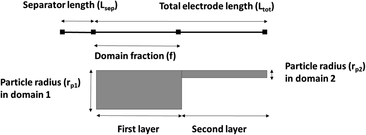 | ||
| Fig. 2 A schematic of the cathode computation domains. | ||
The simulation results were generated using COMSOL Multiphysics 5.4 software. The 1D + 1D Newman model originally considers a 1D representation through the layers of the electrochemical cell in the x direction (Ltot) which is coupled to a second dimension in the y direction (rp) representing radial-symmetric active material particles.24 Therefore, a linear extrusion coupling variable in COMSOL Multiphysics is applied to link the 1D (x direction) and 2D (y direction) geometries to each other. The details on such geometric development using COMSOL Multiphysics can be found here.25 The design parameters are listed in Table 3. The parameter f is the fraction of the total thickness of the positive electrode that represents the layer closer to the separator. The following assumptions are considered for the simulated cell model:18,26,27 (1) no gas generation; (2) homogenous distribution of CB and binder; (3) no solid electrolyte interface (SEI) layer; (4) no contact resistance since no current collector domain; (5) the transport of Li and electrons are continuous at phase boundaries and the local reaction rate is described by the Butler–Volmer equation; (6) electrode active material is composed of spherical particles (including small particles); and (7) volumetric expansion due to intercalation is negligible during discharge.
3.2 Thermal model
A 1D thermal model is coupled with the 1D + 1D electrochemical model. In this model, only natural convection is considered for heat dissipation. An average heat transfer coefficient h value of 5 W m−2 K−1 is considered and adopted from ref. 29. This lumped thermal model assumes uniform temperature across the cell domain thicknesses and ignores heat of mixing effects. The kinetic and thermal parameters are determined from experiments, literature, and by fitting the experimental data. The list is presented in Table 4.| Parameters | Values | Experiment/references |
|---|---|---|
| a See Section 4.3 and Fig. 7. | ||
| Solid diffusivity Ds | 1.00 × 10⁻¹² to 2.14 × 10⁻¹⁴ cm2 s−1a | Experiment |
| Electronic conductivity σs | 3.8 S m−1 | 30 |
| Reaction rate constant k0 | 4.91 × 10⁻¹¹ to 6.37 × 10⁻¹¹ m2 mol−0.5 s−1a | Experiment |
| Initial concentration of Li+ in liquid phase C0l | 1000 mol m−3 | 31 and 32 |
| Maximum concentration of Li+ in solid phase Cs,max | 50060 |
32 |
| Transference number t0+ | 0.4 | 33 |
| Anodic αa and cathodic αc transfer coefficients | 0.5 | 30 |
| Density of NMC811 ρNMC | 4870 kg m−3 | 32 |
| Heat conductivity of NMC811 λNMC | 1.58 W m−1 K−1 | 32 |
| Heat capacity of NMC811 Cp,NMC | 840.1 | 32 |
| Density of separator ρsep | 1009 kg m−3 | 32 |
| Heat conductivity of separator λsep | 0.33 | 32 |
| Heat capacity of separator Cp,sep | 1978.2 J kg−1 K−1 | 32 |
All mass, charge and energy conservation equations are solved in the x direction, except for Li intercalation in the solid phase, which follows Fick's laws of diffusion equation in the y direction of the 2D geometry. The solid phase diffusion in the x direction of the 2D is ignored since it is assumed that the solid particles are not sintered together and are individual particles. Thus, there is no inter-particle solid-state intercalation. The list of governing equations and boundary conditions are given in Table 5.
| Transport descriptions | Governing equations | Boundary conditions |
|---|---|---|
| Mass balance in solid phase |

|

|

|
||
| Mass balance in liquid phase |

|

|

|

|
|
|
||

|
||
| Charge balance in solid phase |

|
i
s|x=sep = 0 |
| σ effs = σsεs | ||

|
||
| Charge conservation in liquid phase |

|

|

|
i l|x=sep = il|x=pos | |

|
i l|x=cc = 0 | |

|
||

|
||
|
||
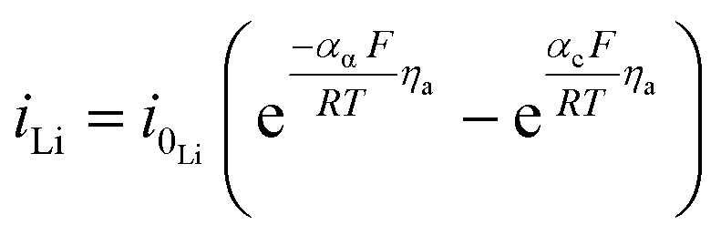
| Cathode electrode kinetics |
|
|
| i 0 = Fk0(Cl)αa(Cs,max − Cs,surf)αa(Cs,surf)αc | ||
| j Li = asin | ||

|
||
| η c = ϕs − ϕl − Ueq | ||
| Lithium foil electrode kinetics |
|
|
| η a = −ϕl | ||
| Heat sources | Q rxn = jLiηc | |

|
||

|
||
|
||
| Energy conservation |

|

|
| Thermodynamic factor |
 31,32
31,32
|
The concentration and temperature dependent diffusion coefficient Dl and ionic conductivity Kl in 1 M LiPF6 (PC/EC/DMC) electrolyte were determined from ref. 31. The entropic coefficient  as a function of lithiation degree in NMC was determined from ref. 32 and implemented in the models via cubic spine interpolation. The experimentally measured kinetic parameters are also incorporated in the model using cubic spine interpolation.
4. Results and discussion
4.1 Effect of material processing on particle morphology
The effect of ball milling conditions on particle morphology were investigated using SEM, BET, and XRD analysis. The SEM images in Fig. 3(a) and (b) confirm that the big secondary spherical particles are broken into small non-spherical primary particles. The statistical image analysis reveals that the average diameter and the standard deviation of the milled particles are 0.93 μm and 0.31 μm respectively as shown in Fig. 3(c). The SEM images of the as received ∼10 μm secondary particles (Fig. S1†) and the analysis of their size distribution (Fig. S2†) using PSA are provided in ESI.† | ||
| Fig. 3 FE-SEM images of NMC primary particles after ball-milling at (a) low and (b) high magnification, statistical analysis of particle size distribution of primary particles (c), and XRD patterns for as-received and ball-milled NMC samples (d). | ||
The surface area of the ball-milled particles is 14.7 m2 g−1, as determined by the BET method. Powder XRD data of the as-received big particles and ball-milled small particles samples was obtained to study the effect of material processing on crystal structure. The XRD patterns for the small and big particles are shown in Fig. 3(d). The big particle powder sample exhibits sharp diffraction peaks due to highly crystalline structure.17 The observed peak broadening and lower relative intensity of the XRD peaks for the small particles can be associated with the relative decrease in crystallinity of the ball-milled small particle powder sample.16,17 The small particle sample shows similar peaks and peak positions as the non-milled samples, which indicates no phase change occurred during ball milling. All the identified peaks are in agreement with reference data of NMC.16,17,34–37 Furthermore, a possible surface layer of Li2CO3 formation was detected by XRD analysis (Fig. S3†) when the milling time was increased to 10 hours. Since the stability of Ni-rich NMC under deionized water is a concern, the milling time was kept for 3 hours to minimize the interaction of AM with the solvent.
4.2 Quantification of microstructural parameters
The thickness and mass loading of the slurry casted cathode disks are correlated in Fig. S4.†The mass loading was found to be a linear function of thickness for both electrodes with small and big particle size. The impact of initial drying temperature on microstructure is discussed further in the supplementary. The SEM images of synthesized cathode structures with big particles in Fig. 4(a) and small particles in Fig. 4(b) show no significant aggregation of the particles from the slurry casting process. Furthermore, the SEM image confirms a uniform distribution of CB for microstructure with small particles. It has been reported that for 50 nm AM particles, percolation of CB particles cannot be achieved before 15 wt% CB, while for 100 nm - 200 nm AM particles percolation can be achieved at 10 wt% CB.38 The reason is a well-interconnected conductive network is hardly probable with AM particle sizes of 50 nm and CB particles of similar sizes (∼50–100 nm) as they can be separated easily. Since the size distribution for the ball-milled particles falls in the range between 0.4–1.6 μm (Fig. 3(c)), a microstructure synthesized with 10 wt% CB should be sufficient to ensure a well-connected CB matrix. Similarly, a 10 wt% binder was chosen to ensure adhesion to the CC and the mechanical stability of the microstructure with respect to thick electrodes (high mass loading), small particles (high surface area), and high CB ratio. | ||
| Fig. 4 SEM images of the slurry casted monolayer electrodes with (a) big and (b) small particle sizes. | ||
One common method to estimate porosity and tortuosity in porous materials is high pressure mercury intrusion porosimetry (MIP), but MIP only provides an estimation of isotropic tortuosity.39,40 In recent years, the use of XCT and FIB tomographic techniques have revolutionized our quantitative understanding of microstructure as well as the transport pathways within LIB electrodes.41 These 3D imaging techniques have enabled us to quantify porosity in 3D volume space and anisotropic tortuosity in both the in-plane and through-plane directions. Here, the monolayer NMC cathodes consisting of big secondary particles were characterized using the Zeiss Xradia Versa 500 XCT system because of its large field of view (FOV). This allows statistically relevant results to be obtained by capturing a large enough volume with big feature sizes. Fig. 5(a) and (b) show the raw greyscale and segmented images respectively. The XCT image data was segmented into two-phases (blue is solid phase and black is pore phase) using the Fiji-ImageJ plugin tool, Trainable Weka Segmentation (TWS).42 Conversely, the single-layer electrodes consisting of small primary particles were characterized using the Zeiss Auriga 40 FIB system because of its ability to resolve samples with small feature sizes at fine image resolution. The sample preparation process for FIB tomography followed the steps reported in ref. 43, where the samples were first embedded in an epoxy resin and subsequently vacuum impregnated. The main reason for using an epoxy resin is to fill up the pore space with chemical elements having low atomic number (Z) to achieve a better SEM contrast between electrode material phase and pore phase for accurate segmentation. The cross-sectional SEM image after FIB milling a few slices is shown in Fig. 6(a). Segmentation steps similar to those used for the XCT images were followed for FIB data to identify solid and pore phases. The porosity was estimated by summing up the voxels of pore phase divided by the total voxels that represent both solid and pore phase. The 3D microstructures of the NMC cathodes consisting of big particles and small particles were reconstructed by the Avizo software and are presented in Fig. 5(c) and 6(b) respectively. The tortuosity factors of the microstructures were calculated in the through-plane direction (the predominant Li+ transport pathway) using the open source MATLAB application TauFactor.44Table 6 lists all the values, and the characterization techniques that were used for microstructural quantification.
 | ||
| Fig. 5 The raw and segmented images from the XCT scanning are shown in (a) and (b) respectively. A 3D rendering of the reconstructed NMC cathode with big particles is shown in (c). | ||
 | ||
| Fig. 6 The cross-sectional SEM view after FIB milling and few slices is shown in (a) and a 3D rendering of the reconstructed NMC cathode with small particles is shown in (b). | ||
| Parameters | Values | Characterization technique |
|---|---|---|
| Average big particle diameter, D50,p1 | 10 μm | PSA, see ESI |
| Average small particle diameter, D50,p2 | 0.93 μm (∼1 μm) | SEM |
| Porosity for big particles, ε1 | 51% | XCT |
| Porosity for small particles, ε2 | 42% | FIB |
| Tortuosity factor for big particles, τ1 | 1.4 | XCT |
| Tortuosity factor for small particles, τ2 | 1.9 | FIB |
4.3 Quantification of transport and kinetic parameters
EIS studies were performed on the monolayer electrodes to understand the impact of material processing condition on transport and kinetic parameters. The Nyquist plots for small and big particles respectively at four different cell voltages corresponding to different depths of discharge (DOD) are presented in Fig. S5(a) and (b).† The solid lines represent the fitting results, which are fitted based on a simplified equivalent circuit,†45,46 as shown in the inset of Fig. S45(a).† In this equivalent circuit, Rs reflects the cell internal contact resistance at the high frequency region, Rct and CPE indicate charge transfer resistance and correlated constant phase element at the intermediate frequency region, and W corresponds to the finite length Warburg impedance at the low frequency region. The Warburg impedance usually consists of both Li+ diffusion in the solution and solid phase. However, the diffusivity in liquid is much faster than that in the solid material. Besides, the contribution from the transport resistance in liquid phase is assumed negligible because of low tortuosity values associated with the relatively high porous microstructures studied here compared to commercial electrodes. Therefore, only solid-state diffusion in AM particles associated with Warburg impedance is considered in this study.The solid phase diffusion coefficient (Ds) can be estimated by using the following equations:45,46
 | (1) |
| Re(Z) = Rs + Rct + σω−1/2 | (2) |
Lithium diffusivities as a function of cell voltage for both small and big particles are plotted in Fig. 7(a). The values are within the range (10−12 to 10−14 cm2 s−1) previously reported by other groups.47,48 In general, Ds decreases with increase of DOD. This is because the Li+ concentration in the bulk of the AM particles increases from its initial value near zero to a saturation value, owning to a progressive harder Li+ insertion process upon discharge.49,50 However, a slight increase in diffusivity at 3.9 V for the big particles is observed. This could be ascribed to micro-cracking in secondary particles caused by phase transformations and structural distortions.51 Such microcracks are responsible for electrolyte infiltration towards the center of the secondary particles, which in turn reduces the diffusion length for Li+, leading to an apparent increase in diffusivity.52 Another interesting observation is that the diffusivity for small particles is higher than the larger particles. This maybe because rigid crystal structures cannot facilitate Li+ diffusion unlike less crystallized or amorphous structures.53,54 As confirmed by the above XRD results, the small particles exhibit a lower degree of crystallinity relative to larger particles.
 | ||
| Fig. 7 Solid-state diffusion coefficient (a) and reaction rate constant (b) as a function of cell voltage. | ||
The fitted values of Rct and σ for both small and big particles at different voltages are concluded in Table 7. For both particles, charge transfer resistance increases with increasing DOD. Notably, the big particles exhibit higher Rct values compare to the small particles except at high DOD (namely 3.3 V). The elevation in Rct with increasing DOD can be assigned to the worsening ionic diffusivity in electrolyte and the poorer electronic conductivity in the AM.55,56 Since no visible CB agglomeration in electrode microstructures were confirmed by the SEM images, it is plausible that ionic resistance in electrolyte predominately contributed to Rct at high DOD leading to a higher Rct at 3.3 V for the small particles compared to the big. XCT and FIB tomography further confirmed that the microstructures with small particles yield ∼10% less porosity than the big particles. This reduction in porosity also increased the tortuosity and as a result decreased the effective diffusivity and effective conductivity of the electrolyte.
| Voltage | Small particles | Big particles | ||
|---|---|---|---|---|
| R ct (ohm) | σ (ohm per s1/2) | R ct (ohm) | σ (ohm per s1/2) | |
| 4.2 V | 26.38 | 7.23 | 31.33 | 10.50 |
| 3.9 V | 29.00 | 7.87 | 32.99 | 6.64 |
| 3.6 V | 32.66 | 8.79 | 35.68 | 12.97 |
| 3.3 V | 40.21 | 8.59 | 38.42 | 17.92 |
The reaction rate constant (k0) can be determined from Rct using the modified equation below:57,58
 | (3) |
In this equation, Cl is the concentration of Li+ in the electrolyte, Cs,max is the maximum theoretical concentration of Li+ in the solid phase, and Cs is the concentration of Li+ at the surface of AM particles. The calculated k0 is plotted as a function of cell voltage in Fig. 7(b). As seen, the small particles display slightly faster charge transfer reaction rate between the electrolyte and the surface of the AM particles. Two interesting phenomena can be observed: an increase in k0 at higher DOD corresponding to 3.6 V and 3.3 V, and a higher k0 value for small particles despite having a higher Rct at 3.3 V.
The reason for the increase in k0 at high DOD is because of the influence of Cs,max − Cs on the value of k0. At high DOD, Cs approaches Cs,max and as a consequence a smaller value for Cs,max − Cs yields a higher value of k0. Moreover, based on the experimental data extracted from EIS results, Cs,max − Cs,big > Cs,max − Cs,small at any given DOD as the solid phase concentration in small particles (Cs,small) is higher than the solid phase concentration in big particles (Cs,big) due to short diffusion length and large interfacial surface area. This explains why the smaller particles have a higher k0 even with a higher Rct at 3.3 V.
4.4 Simulation results of bi-layer electrodes
A direct, time-dependent solver of MUMPS was used in COMSOL Multiphysics to solve the constitutive partial differential equations (PDE). The relative tolerance was 0.0001 and the absolute tolerance was a scaled factor of 0.01. The cells were discharged with a cut-off voltage of 3.4 V. Dimensionless geometries were implemented for particle radius and cell thickness to improve computational speed and to avoid numerical convergence issues.First, the simulated cell voltage vs. specific capacity curves for monolayer electrodes with big particles and small particles were validated against their respective experimental data acquired from coin cells. The thickness and C-rate were 200 μm and 0.5C respectively. Fig. 8 confirms both monolayer models are in good agreement with the half-cell measurements for big and small particles. Afterwards, the so-validated models were used to construct a 400 μm bi-layer cathode, where half of the layer (200 μm) was constructed with big particles and the other half was constructed with small particles. Table 8 shows the design matrix that is considered to evaluate the performance of the bi-layer cathodes.
 | ||
| Fig. 8 Simulated model validation with experimental data for half-cells. | ||
| Type of bi-layer cathodes | First layer next to separator | Second layer next to CC | Domain fraction | Each layer thickness |
|---|---|---|---|---|
| BLC1 | Big particle | Small particle | 1/2 | 200 μm |
| BLC2 | Small particle | Big particle | 1/2 | 200 μm |
The specific capacity as a function of cell voltage for bi-layer cathodes are plotted in Fig. 9(a)–(d). The first discharge capacity of the bi-layer models are compared with monolayer models at C-rates of 1C, 2C, 3C and 4C. At all C-rates, both BLC1 and BLC2 exhibit higher capacity than the monolayer electrode consisting of big particles, which is the conventional electrode microstructure used commercially. As C-rate increases to 4C, the discharge capacity of BLC1 approaches the discharge capacity of the monolayer electrodes with small particles. Small particle sizes are desirable as they increase interfacial surface area and reduce the diffusion length for lithium ions in the AM. A large interfacial surface area is important for ensuring an adequate rate of ion transfer between solid and liquid phases.14 However, an increased interfacial surface area also results in increased side reactions with the electrolyte and promotes the formation of cathode electrolyte interface (CEI) layer. This layer obstructs the diffusion of Li+ and results in large irreversible capacity. Moreover, a decrease in particle size yields a low tap density, which translates into low volumetric energy density. These largely prevent the use of small particles in commercial monolayer electrodes. In the model, the effect of CEI is not included and the cell performance is evaluated based on first discharge capacity. However, it is worth noting that positioning big particles in a layer next to the separator like BLC1 may assist with circumventing large capacity loss due to reduced side reaction induced by decreased interfacial surface area.
 | ||
| Fig. 9 Simulated first discharge capacity as a function of cell voltage at (a) 1C, (b) 2C, (c) 3C, and (d) 4C. | ||
The resulting solid phase lithiation fraction across the dimensionless electrode thickness at 2C and 4C are shown in Fig. 10(a) and (b) respectively. Here, the lithiation fraction is presented as the ratio of Li+ concentration at the centre of the AM particles to maximum theoretical concentration in the solid phase at the end of cut-off voltage. For the electrode thickness, zero is next to the separator, whereas 1 is next to CC. Both BLC1 and BLC2 have higher electrode utilization next to the CC as seen in Fig. 10(a), although, BLC1 displays overall better AM utilization along the thickness of the electrode. In fact, Li+ concentration in AM particles goes up at the interface between the first and second layer in BLC1, while the concentration profile gradually decreases along the thickness for BLC2 and monolayer models. This is can be linked to the presence of small particles in the second layer or BLC1 which have higher rate of Li+ intercalation due to large interfacial surface area, shorter diffusion pathway, and faster kinetics (Ds and k0) as discussed in Sections 4.2 and 4.3 respectively. Additionally, a higher volume fraction of small particles in the second layer of BLC1 means a higher amount of Li+ is stored in the AM. Since both the BLC1 and the monolayer with small particles, achieve high discharge capacities at 4C, their solid phase concentration profiles are compared in Fig. 10(b). A ∼5% increase of Li+ concentration in AM particles can be noticed along the electrode thickness (0.5 ≤ Ltot ≤ 0.9) for the BLC1 structure. A rapid drop in lithiation at Ltot ∼ 0.9, followed by a plateau can be also noticed. The reasons are explained in the following paragraph (Fig. 10(d)).
 | ||
| Fig. 10 Comparison of solid phase concentration ratio along the electrode thickness at (a) 2C and (b) 4C, and electrolyte concentration along the electrode thickness at (c) 2C and (d) 4C. | ||
Fig. 10(c) and (d) show the electrolyte concentration across the electrode thickness at the end of cut-off voltage. It can be seen in Fig. 10(c) that the monolayer model with big particles suffers from smaller Li+ concentration gradients as compared to the other three cathode structures at 2C. This can be attributed to two factors: the monolayer composed of big particles has a higher porosity throughout its electrode thickness, which permits a greater amount of Li+ to be transported to the reaction zone closer to the CC. Concurrently, the time required for Li+ to intercalate into the AM of big particles is longer due to longer diffusion length. As a result, more Li+ can be found in the liquid phase than the solid phase, particularly at high C-rates. This analysis is consistent with the result presented in Fig. 10(a), where the electrode utilization for the monolayer with big particles is the lowest among all the microstructures. The largest electrolyte depletion closer to the CC can be noticed for the monolayer with small particles owing to its lower porosity throughout the electrode thickness. BLC2 retains higher electrolyte concentration at the back of the electrode compared to BLC1. This can be again linked to the presence of higher porosity and longer diffusion length through big particles in the second layer of BLC2. The electrolyte concentration profile through the electrode thickness for BLC1 and small particles at 4C can be seen in Fig. 10(d). The result illustrates that at such a high C-rate the retardation of liquid phase transport becomes severe and the electrolyte concentration reaches zero near the CC. This also explains the sharp drop in lithiation fraction next to the CC in Fig. 10(b) since no Li+ are available for solid phase intercalation. Despite both structures having the same porosity closer to the CC, BLC1 exhibits slightly higher electrolyte concentration. This can be ascribed to the presence of higher porosity in the first layer, which has given more Li+ access to the depth of the second layer. The plateau at Ltot > 0.9 is related to the minimum lithiation fraction (∼0.3) in the NMC corresponding to an upper cut-off voltage of 4.2 V. A higher cut-off voltage (>4.2 V) may lead to structural instability, gas generation, and parasitic reactions between the surface of the AM and electrolyte.59–61
In this coupled 1D thermal model, the density and specific heat capacity are calculated based on the length-averaged values of each component inside the half cell and presented in eqn (4). The thermal conductivity along the thickness is given in eqn (5).
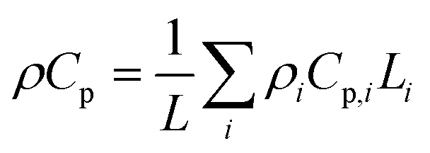 | (4) |
 | (5) |
In Fig. 11(a), the total heat generation rate in bi-layer and monolayer electrodes are compared at 4C. The results reveal that the total heat generation rate in the first layer of BLC1 is the lowest. At the interface of first and second layer, the heat generation rate increases from 15 W m−3 to 30 W m−3. The opposite trend can be observed for BLC2, where the heat generation drops from 20W m−3 to 10 W m−3 at the interface between the layers. It is known that the ohmic loss in the electrolyte is the main source for most of the heat generation in cathode, which is aggravated by the steep concentration gradient in a thick cathode due to insufficient ionic conductivity under high discharge rate.62 The layer composed with big particles inherit higher porosity and lower tortuosity compare to the layer composed with small particles. This leads to a higher effective diffusivity that in turn decreases the slope of the electrolyte concentration gradient and hence the heat generation rate in the layer comprised of big particles. Nonetheless, another interesting comparison can be noticed between BLC1 and the monolayer with big particles. Despite the monolayer with big particles having a higher porosity throughout its entire thickness, BLC1 with graded porosity (high to low) exhibits lower heat generation. This can be related to the presence of small particles in the second layer, where the magnitude of overpotential decreases with decreasing particle size due to higher reaction areas leading to lower irreversible reaction heat,63 and thus less overall heat generation. An increase in heat generation at Ltot ≥ 0.9 can be noticed for BLC1 and small particles. This is related to Joule heating caused by charge transport limitation in the liquid phase (Fig. 10(d)).
 | ||
| Fig. 11 (a) Total heat generation rate along the electrode thickness and (b) comparison of Ragone plot for bi-layer and monolayer cathodes at 4C. | ||
A Ragone plot is presented in Fig. 11(b) to compare the performance of bi-layer electrodes with monlayer electrodes at 4C. The specific energy (Ecell) is plotted against the average specific power (Pcell) and both axes are on logarithmic scale. Ecell and Pcell are calculated using the following equations:64
 | (6) |
 | (7) |
Conclusion
In this work, the potential benefit to use bi-layer cathodes over single layer cathodes for thick electrode applications is investigated. Simulation results reveal that bi-layer cathodes exhibit promising performance with improved ion diffusion and discharge capacity. The effect of processing conditions on particle morphology is investigated for NMC811 cathode material. Single layer electrodes with two distinct particle sizes are fabricated to assess resulting microstructural, transport, and kinetic features by employing various physical and electrochemical characterization techniques. The extracted values are used as input parameters to develop bi-layer numerical models. The simulations are carried out to understand the transport behaviour and estimate cell performance for thick graded electrodes. The summarized conclusion includes:(1) Porosity decreases with decreasing particle size in a microstructure. This favours faster transport in solid phase but slower transport in liquid phase.
(2) Solid phase diffusivity and reaction rate constant increases with decreasing particle size. The facilitation of diffusivity can be connected to change in crystallinity to amorphous structure. The increase in rate constant can be credited to a combination of reduced charge transfer resistance and higher solid phase concentration.
(3) Both BLC1 and BLC2 display higher electrode utilization next to the CC compared to monolayer electrodes. At high C-rate (4C), BLC1 shows similar discharge capacity as the monolayer electrode with small particles. With an increase in C-rate, liquid phase transport becomes the limiting factor.
(4) For both power and energy density application, BLC1 could be a potential electrode candidate for commercial purposes.
For future work, the authors wish to fabricate thick bi-layer cathodes to confirm the performance improvement as compared to monolayer electrodes with single sized particles. However, controlling CB percolation and binder migration become more challenging in thick electrodes. The finished product is dependent on a combination of slurry compositions, viscosity, and drying conditions. Furthermore, a second deposition step is required including material processing and handling of small particles. Future experimental work should explore whether the prospect of bi-layer electrodes outweigh the constraints associated with their manufacturing process which includes novel deposition techniques. For example, Huang et al. reported on successful synthesis of a thin (12.2 μm) bi-layer anode structure through spray deposition technique65 in which both layers consist of nano-sized particles. Their experimental results confirmed superior charge (Li extraction) capacity and coulombic efficiency at high current density (2C, 4C) for this bi-layer electrode compare to single layer electrodes. Further research is required to investigate the transferability of such synthesis technique along with other techniques to large-scale industrial production.
Nomenclature
| A | Electrode area (m2) |
| a s | Interfacial area (m2 m−3) |
| C l | Li+ concentration in liquid (mol m−3) |
| C p | Specific heat capacity (J kg−1 K−1) |
| C s | Li+ concentration in solid (mol m−3) |
| D l | Diffusion coefficient in liquid (m2 s−1) |
| D s | Diffusion coefficient in solid (m2 s−1) |
| E cell | Cell specific energy (W h kg−1) |
| f | Domain fraction (—) |
| f e | Activity coefficient (—) |
| F | Faraday constant (C mol−1) |
| i 0 | Exchange current density (A m−2) |
| i l | Liquid phase current density (A m−2) |
| i n | Local current density (A m−2) |
| i s | Solid phase current density (A m−2) |
| I app | Applied current density (A m−2) |
| j Li | Reaction current density (A m−3) |
| k 0 | Reaction rate constant (m2 mol−0.5 s−1) |
| h | Convective heat transfer coefficient capacity (W m−2 K−1) |
| L pos | Cathode thickness (m) |
| L sep | Separator thickness (m) |
| M | Mass loading (g m−2) |
| n | Number of electrons (—) |
| P cell | Specific power (W kg−1) |
| Q ohm | Ohmic heat generation rate (W m−3) |
| Q rev | Reversible or entropic heat generation rate W m−3) |
| Q rxn | Reaction heat generation rate W m−3) |
| r p | Particle radius (m) |
| R | Gas constant (J mol−1 K−1) |
| t | Time (s) |
| t p | Transfer coefficient (—) |
| T | Temperature (K) |
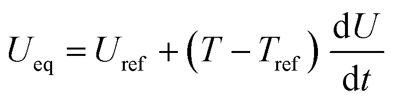
| U eq | Open circuit potential (V) |
| U ref | Open circuit potential of an electrode reaction (V) |
| dU/dT | Entropic coefficient (mV K−1) |
Greek symbols
| α | Symmetry factor (—) |
| ε | Porosity or volume fraction of liquid (—) |
| η a | Surface overpotential at Li foil (V) |
| η c | Surface overpotential at cathode (V) |
| γ | Thermodynamic factor (—) |
| τ | Tortuosity (—) |
| K | Electrolyte conductivity (S m−1) |
| σ | Solid phase conductivity (S m−1) |
| ϕ l | Electrolyte potential (V) |
| ϕ s | Electrode potential (V) |
| ρ | Material density (kg m−3) |
| λ | Thermal conductivity (W m−1 K−1) |
Conflicts of interest
The authors declare no conflicts of interest.Acknowledgements
The authors thank Dr Yuhua Xia for EIS tests and Dr Mengzheng Ouyang for FIB imaging. The authors also thank Dr Catalina Pino-Muñoz and Dr Antonio Bertei for the insightful discussions. This work is supported by the U.S. Department of Education and the EPSRC project EP/M009521/1 “Enabling next generation lithium batteries”.References
- W. Tiedemann and J. Newman, Maximum Effective Capacity in an Ohmically Limited Porous Electrode, J. Electrochem. Soc., 1975, 122(11), 1482 CrossRef CAS.
- T. F. Fuller and M. Doyle, Simulation and Optimization of the Dual Lithium-Ion Insertion Cell, J. Electrochem. Soc., 1994, 141(1), 1–10 CrossRef CAS.
- V. Srinivasan and J. Newman, Design and Optimization of a Natural Graphite/Iron Phosphate Lithium-Ion Cell, J. Electrochem. Soc., 2004, 151(10), A1530–A1538 CrossRef CAS.
- H. H. Zheng, et al., A comprehensive understanding of electrode thickness effects on the electrochemical performances of Li-ion battery cathodes, Electrochim. Acta, 2012, 71, 258–265 CrossRef CAS.
- T. D. Tran, et al., Rate effect on lithium-ion graphite electrode performance, J. Appl. Electrochem., 1996, 26(11), 1161–1167 CrossRef CAS.
- Z. J. Du, et al., Understanding limiting factors in thick electrode performance as applied to high energy density Li-ion batteries, J. Appl. Electrochem., 2017, 47(3), 405–415 CrossRef CAS.
- W. Wu, X. R. Xiao and X. S. Huang, The effect of battery design parameters on heat generation and utilization in a Li-ion cell, Electrochim. Acta, 2012, 83, 227–240 CrossRef CAS.
- V. Ramadesigan, et al., Optimal Porosity Distribution for Minimized Ohmic Drop across a Porous Electrode, J. Electrochem. Soc., 2010, 157(12), A1328–A1334 CrossRef CAS.
- Y. Dai and V. Srinivasan, On Graded Electrode Porosity as a Design Tool for Improving the Energy Density of Batteries, J. Electrochem. Soc., 2015, 163(3), A406–A416 CrossRef.
- E. Hosseinzadeh, J. Marco and P. Jennings, The impact of multi-layered porosity distribution on the performance of a lithium ion battery, Appl. Math. Model., 2018, 61, 107–123 CrossRef.
- J. Li, et al., Toward Low-Cost, High-Energy Density, and High-Power Density Lithium-Ion Batteries, Jom, 2017, 69(9), 1484–1496 CrossRef CAS.
- S. Golmon, K. Maute and M. L. Dunn, A design optimization methodology for Li+ batteries, J. Power Sources, 2014, 253, 239–250 CrossRef CAS.
- S. T. Taleghani, et al., The Effect of Structural Properties of a Two-Layered Electrode on the Li-Ion Battery Polarization, J. Electrochem. Soc., 2019, 166(2), A225–A235 CrossRef CAS.
- N. S. Xue, et al., Optimization of a Single Lithium-Ion Battery Cell with a Gradient-Based Algorithm, J. Electrochem. Soc., 2013, 160(8), A1071–A1078 CrossRef CAS.
- W. B. Du, et al., Effect of cycling rate, particle size and transport properties on lithium-ion cathode performance, Int. J. Heat Mass Transfer, 2010, 53(17–18), 3552–3561 CrossRef CAS.
- S.-B. Kim, et al., Nanostructure cathode materials prepared by high-energy ball milling method, Mater. Lett., 2011, 65(21–22), 3313–3316 CrossRef CAS.
- M. Stein, et al., Probing the Effect of High Energy Ball Milling on the Structure and Properties of LiNi1/3Mn1/3Co1/3O2 Cathodes for Li-Ion Batteries, J. Electrochem. Energy Convers. Storage, 2016, 13(3) CAS.
- M. Doyle and J. Newman, Comparison of Modeling Predictions with Experimental Data from Plastic Lithium Ion Cells, J. Electrochem. Soc., 1996, 143(6), 1890 CrossRef.
- M. Doyle and J. Newman, The Use of Mathematical-Modeling in the Design of Lithium Polymer Battery Systems, Electrochim. Acta, 1995, 40(13–14), 2191–2196 CrossRef CAS.
- M. Doyle and J. Newman, Analysis of capacity-rate data for lithium batteries using simplified models of the discharge process, J. Appl. Electrochem., 1997, 27(7), 846–856 CrossRef CAS.
- M. Doyle and J. Newman, Modeling the Performance of Rechargeable Lithium-Based Cells – Design Correlations for Limiting Cases, J. Power Sources, 1995, 54(1), 46–51 CrossRef CAS.
- M. Doyle, T. F. Fuller and J. Newman, Modeling of Galvanostatic Charge and Discharge of the Lithium Polymer Insertion Cell, J. Electrochem. Soc., 1993, 140(6), 1526–1533 CrossRef CAS.
- M. Wang, X. R. Xiao and X. S. Huang, A multiphysics microstructure-resolved model for silicon anode lithium-ion batteries, J. Power Sources, 2017, 348, 66–79 CrossRef CAS.
- J. B. Habedank, et al., Increasing the Discharge Rate Capability of Lithium-Ion Cells with Laser-Structured Graphite Anodes: Modeling and Simulation, J. Electrochem. Soc., 2018, 165(7), A1563–A1573 CrossRef CAS.
- L. Cai and R. E. White, Mathematical modeling of a lithium ion battery with thermal effects in COMSOL Inc. Multiphysics (MP) software, J. Power Sources, 2011, 196(14), 5985–5989 CrossRef CAS.
- Y. H. Ye, et al., Electro-thermal modeling and experimental validation for lithium ion battery, J. Power Sources, 2012, 199, 227–238 CrossRef CAS.
- W. Mei, et al., The effect of electrode design parameters on battery performance and optimization of electrode thickness based on the electrochemical–thermal coupling model, Sustainable Energy Fuels, 2019, 3(1), 148–165 RSC.
- D. P. Finegan, et al., Characterising the structural properties of polymer separators for lithium-ion batteries in 3D using phase contrast X-ray microscopy, J. Power Sources, 2016, 333, 184–192 CrossRef CAS.
- Y. H. Ye, et al., Effect of thermal contact resistances on fast charging of large format lithium ion batteries, Electrochim. Acta, 2014, 134, 327–337 CrossRef CAS.
- T. Danner, et al., Thick electrodes for Li-ion batteries: a model based analysis, J. Power Sources, 2016, 334, 191–201 CrossRef CAS.
- L. O. Valoen and J. N. Reimers, Transport Properties of LiPF6-Based Li-Ion Battery Electrolytes, J. Electrochem. Soc., 2005, 152(5), A882–A891 CrossRef CAS.
- J. Sturm, et al., Modeling and simulation of inhomogeneities in a 18650 nickel-rich, silicon-graphite lithium-ion cell during fast charging, J. Power Sources, 2019, 412, 204–223 CrossRef CAS.
- D. Djian, et al., Macroporous poly(vinylidene fluoride) membrane as a separator for lithium-ion batteries with high charge rate capacity, J. Power Sources, 2009, 187(2), 575–580 CrossRef CAS.
- J. Zhu, et al., Crystal structure and size effects on the performance of Li[Ni1/3Co1/3Mn1/3]O2 cathodes, J. Mater. Res., 2014, 30(02), 286–294 CrossRef.
- H. Sclar, et al., On the Performance of Li[Ni1/3Mn1/3Co1/3]O2 Nanoparticles as a Cathode Material for Lithium-Ion Batteries, J. Electrochem. Soc., 2009, 156(11) CrossRef CAS.
- H. Y. Zou, et al., A novel method to recycle mixed cathode materials for lithium ion batteries, Green Chem., 2013, 15(5), 1183–1191 RSC.
- X. Li, et al., Dual functions of zirconium modification on improving the electrochemical performance of Ni-rich LiNi0.8Co0.1Mn0.1O2, Sustainable Energy Fuels, 2018, 2(2), 413–421 RSC.
- A. Awarke, et al., Percolation–tunneling modeling for the study of the electric conductivity in LiFePO4 based Li-ion battery cathodes, J. Power Sources, 2011, 196(1), 405–411 CrossRef CAS.
- L. Froboese, et al., Mercury intrusion for ion- and conversion-based battery electrodes – structure and diffusion coefficient determination, Mater. Charact., 2017, 133, 102–111 CrossRef CAS.
- F. A. L. Dullien, Porous media: fluid transport and pore structure, Academic Press, San Diego, 2nd edn, 1992 Search PubMed.
- O. O. Taiwo, et al., The use of contrast enhancement techniques in X-ray imaging of lithium-ion battery electrodes, Chem. Eng. Sci., 2016, 154, 27–33 CrossRef CAS.
- I. Arganda-Carreras, et al., Trainable Weka segmentation: a machine learning tool for microscopy pixel classification, Bioinformatics, 2017, 33(15), 2424–2426 CrossRef CAS.
- M. Biton, et al., Enhanced Imaging of Lithium Ion Battery Electrode Materials, J. Electrochem. Soc., 2017, 164(1), A6032–A6038 CrossRef CAS.
- S. J. Cooper, et al., TauFactor: an open-source application for calculating tortuosity factors from tomographic data, SoftwareX, 2016, 203–210 CrossRef.
- Q. Wang, et al., A facile method of improving the high rate cycling performance of LiNi1/3Co1/3Mn1/3O2 cathode material, J. Alloys Compd., 2016, 686, 267–272 CrossRef CAS.
- K. Sahni, et al., H3PO4 treatment to enhance the electrochemical properties of Li(Ni1/3Mn1/3Co1/3)O2 and Li(Ni0.5Mn0.3Co0.2)O2 cathodes, Electrochim. Acta, 2019, 301, 8–22 CrossRef CAS.
- C.-H. Chen, et al., Development of Experimental Techniques for Parameterization of Multi-scale Lithium-ion Battery Models, J. Electrochem. Soc., 2020, 167(8) Search PubMed.
- S. Chen, et al., Ni-Rich LiNi0.8Co0.1Mn0.1O2 Oxide Coated by Dual-Conductive Layers as High Performance Cathode Material for Lithium-Ion Batteries, ACS Appl. Mater. Interfaces, 2017, 9(35), 29732–29743 CrossRef CAS.
- C. H. Wang, et al., Unveiling the critical role of interfacial ionic conductivity in all-solid-state lithium batteries, Nano Energy, 2020, 72, 1–6 Search PubMed.
- S. Atlung, K. West and T. Jacobsen, Dynamic Aspects of Solid-Solution Cathodes for Electrochemical Power Sources, J. Electrochem. Soc., 1979, 126(8), 1311–1321 CrossRef CAS.
- J. M. Lim, et al., Intrinsic Origins of Crack Generation in Ni-rich LiNi0.8Co0.1Mn0.1O2 Layered Oxide Cathode Material, Sci Rep., 2017, 7, 39669 CrossRef CAS.
- S. H. Xia, et al., Chemomechanical interplay of layered cathode materials undergoing fast charging in lithium batteries, Nano Energy, 2018, 53, 753–762 CrossRef CAS.
- J. Wang, et al., Electrochemical properties of 0.6Li[Li1/3Mn2/3]O2–0.4LiNixMnyCo1−x−yO2 cathode materials for lithium-ion batteries, J. Power Sources, 2012, 218, 128–133 CrossRef CAS.
- S. M. Zhang, et al., Li ion diffusivity and electrochemical properties of FePO4 nanoparticles acted directly as cathode materials in lithium ion rechargeable batteries, Electrochim. Acta, 2013, 88, 287–293 CrossRef CAS.
- P.-P. Wang, et al., Low temperature electrochemical performance of β-Li V2O5 cathode for lithium-ion batteries, Electrochim. Acta, 2015, 169, 440–446 CrossRef CAS.
- Y. Zhou, et al., A porous LiFePO4 and carbon nanotube composite, Chem. Commun., 2010, 46(38), 7151–7153 RSC.
- E. P. Randviir, A cross examination of electron transfer rate constants for carbon screen-printed electrodes using Electrochemical Impedance Spectroscopy and cyclic voltammetry, Electrochim. Acta, 2018, 286, 179–186 CrossRef CAS.
- E. P. Randviir and C. E. Banks, Electrochemical impedance spectroscopy: an overview of bioanalytical applications, Anal. Methods, 2013, 5(5), 1098–1115 RSC.
- J. Li, et al., Study of the Failure Mechanisms of LiNi0.8Mn0.1Co0.1O2Cathode Material for Lithium Ion Batteries, J. Electrochem. Soc., 2015, 162(7), A1401–A1408 CrossRef CAS.
- L. X. Geng, et al., High accuracy in situ direct gas analysis of Li-ion batteries, J. Power Sources, 2020, 466, 1–9 CrossRef.
- R. Jung, et al., Oxygen Release and Its Effect on the Cycling Stability of LiNixMnyCozO2 (NMC) Cathode Materials for Li-Ion Batteries, J. Electrochem. Soc., 2017, 164(7), A1361–A1377 CrossRef CAS.
- L. Rao and J. Newman, Heat-generation rate and general energy balance for insertion battery systems, J. Electrochem. Soc., 1997, 144(8), 2697–2704 CrossRef CAS.
- A. H. N. Shirazi, M. R. Azadi Kakavand and T. Rabczuk, Numerical Study of Composite Electrode’s Particle Size Effect on the Electrochemical and Heat Generation of a Li-Ion Battery, J. Nanotechnol. Eng. Med., 2015, 6(4), 041003-1 Search PubMed.
- E. Hosseinzadeh, J. Marco and P. Jennings, Electrochemical–Thermal Modelling and Optimisation of Lithium-Ion Battery Design Parameters Using Analysis of Variance, Energies, 2017, 10(9), 1–22 Search PubMed.
- C. Huang, et al., A two layer electrode structure for improved Li Ion diffusion and volumetric capacity in Li Ion batteries, Nano Energy, 2017, 31, 377–385 CrossRef CAS.
Footnote |
| † Electronic supplementary information (ESI) available. See DOI: 10.1039/d0se01611j |
| This journal is © The Royal Society of Chemistry 2021 |