
 Open Access Article
 This Open Access Article is licensed under a
 Creative Commons Attribution 3.0 Unported Licence
D–A–π–A organic dyes with tailored green light absorption for potential application in greenhouse-integrated dye-sensitized solar cells†
Alessio
Dessì
 *a,
Dimitris A.
Chalkias
b,
Stefania
Bilancia
c,
Adalgisa
Sinicropi
acd,
Massimo
Calamante
ae,
Alessandro
Mordini
ae,
Aggeliki
Karavioti
b,
Elias
Stathatos
*b,
Lorenzo
Zani
a and
Gianna
Reginato
*a
*a,
Dimitris A.
Chalkias
b,
Stefania
Bilancia
c,
Adalgisa
Sinicropi
acd,
Massimo
Calamante
ae,
Alessandro
Mordini
ae,
Aggeliki
Karavioti
b,
Elias
Stathatos
*b,
Lorenzo
Zani
a and
Gianna
Reginato
*a
aInstitute of Chemistry of Organometallic Compounds (CNR-ICCOM), Via Madonna del Piano 10, I-50019 Sesto Fiorentino, Italy. E-mail: a.dessi@iccom.cnr.it; gianna.reginato@iccom.cnr.it
bNanotechnology & Advanced Materials Laboratory, Department of Electrical and Computer Engineering, University of Peloponnese, GR-26334 Patras, Greece
cDepartment of Biotechnology, Chemistry and Pharmacy, University of Siena, Via A. Moro 2, I-53100, Siena, Italy
dCSGI, Consorzio per lo Sviluppo dei Sistemi a Grande Interfase, Sesto Fiorentino I-50019, Italy
eDepartment of Chemistry “U. Schiff”, University of Florence, Via della Lastruccia 13, I-50019 Sesto Fiorentino, Italy
First published on 15th January 2021
Abstract
In this paper, we present the design and synthesis of three organic dyes specially developed for the fabrication of dye-sensitized solar cells for application in greenhouses cladding. The dyes (BTD-DTP1–3) are based on a benzothiadiazole (BTD)–dithienopyrrole (DTP) scaffold, and were assembled by using direct arylation reactions, allowing significant reduction of the number of synthetic and purification steps compared to classic cross-coupling procedures. Thanks to their structural design, the dyes absorb light in the green part of the visible spectrum while allowing good transmittance in the red and blue regions, thus ensuring high compatibility with light absorption by plants. Dye-sensitized solar cells built with the three dyes provided energy conversion efficiencies (ECEs) comparable or even superior to those obtained with the reference Ru-based dye N719, especially when using a thin and semitransparent TiO2 layer (up to 8.77%). The photovoltaic performances are discussed considering the need to reach the best compromise between good ECE values and high levels of weighed transparency against the main plant photoreceptors.
Introduction
The efficient utilization of renewable energy sources is a major scientific challenge and probably the only option available to our society to meet the ever increasing global energy demand and simultaneously reduce CO2 emissions and global warming.1 In this context, conversion of solar light is particularly important, as it is abundant, widely distributed, free and practically inexhaustible,2 as confirmed by the progress of photovoltaic (PV) technology and the continuous increase in its global installed capacity (12% increase of the solar PV market in 2019).3 However, there is still a huge need to further improve energy production from the sun. To achieve this goal, the development of new PV technologies and the extension of the existing ones to novel applications can play a decisive role.4 Following this approach, integration of PVs into agricultural settings such as greenhouses, also known as “agrivoltaics”,5 recently became a relevant subject of research, aimed at combining the exploitation of renewable energy with the enhancement of food production and quality.6,7 However, almost all PV installations on greenhouses worldwide are made with conventional silicon-based modules, which is not advantageous because they are opaque and thus prevent light transmission, hampering plant growth and crop productivity. As a matter of fact, it was estimated that the roof coverage by crystalline Si-modules should not exceed 30%,8–10 a value which is even lowered to 10% for crops of high economic value, or in cases where food yield should be prioritized.11,12New generation photovoltaics such as organic solar cells (OSCs)13–15 or dye-sensitized solar cells (DSSCs)16,17 might be a valid alternative to overcome this drawback.18,19 The latter, in particular, can represent an ideal solution because they can be layered on glass or plastic, giving coloured, lightweight and transparent devices,20,21 able to work under a wide array of lighting conditions, without suffering from angular dependence of incident light.22 A DSSC is an electrochemical device that uses dye molecules adsorbed on a nanocrystalline semiconductor (generally TiO2) to harvest sunlight and generate electricity.23 Thanks to photo-excitation, at the anode an electron is promoted from the HOMO of the dye to its LUMO, and then transferred to the conduction band of the semiconductor. The original state of the dye is then restored by electron donation from a redox mediator. In the meantime, the electron travels through the external circuit (generating an electric current) and is collected at the cathode, where the reduction of the oxidized redox mediator takes place. Obviously, the overall efficiency of the final device is strongly influenced by the sensitizer used and thus, especially in the context of agrivoltaics, there is a considerable innovation potential in the search of suitable dyes, potentially able to harvest incident light for electricity generation without adversely affecting plant growth. Indeed, it is well known that the “photosynthetically active region” (PAR), that is the region of the spectrum utilized by plants, is between 400 and 750 nm. However, not all light is converted with the same efficiency and two peaks occur in the blue (425–475 nm) and red (625–750 nm) regions of the visible spectrum,24 corresponding to the area of activity of the most diffused forms of chlorophyll, a and b, as well as red and far-red phytochromes.25,26 For these reasons, the design of tailored sensitizers capable of absorbing visible light mostly in the green region, while transmitting blue and red wavelengths, can be a convenient approach to a greenhouse-integrated DSSC PV system, provided devices with moderate-to-good efficiency can be obtained. Such an approach has been already exploited in the field of organic solar cells containing near-IR absorbing polymer/acceptor blends,27–29 tandem photonic crystals,30 and DSSCs. In the latter case, two examples using simple derivatives of the well-known Ru-based dye N71931 and a series of diketopyrrolopyrrole-derived organic dyes32 were described, the latter showing relatively low power conversion efficiencies (≤2.24%).
More recently, we prepared a series of organic thiazolo[5,4-d]thiazole-containing sensitizers, TTZ8–12 (Fig. 1) specifically designed for improving the light absorption capability in the green part of the visible spectrum while maintaining good transparency in the blue and red regions.33 Such dyes were used to build semitransparent DSSCs, yielding 5.6–6.1% power conversion efficiencies. Dyes like TTZ8–12 are based on push–pull D–π–A structures, in which a donor group (D) is connected to an acceptor/anchoring group (A) through a conjugated bridge (π, Fig. 1), and are common among metal-free dyes for DSSCs as they can be easily prepared and purified. Furthermore, their optical, electronic and electrochemical properties can be finely modulated by simple modifications of the D, π and A moieties.34 To better refine such properties, it is also possible to introduce additional acceptor units between the donor and the π-spacer, leading to D–A–π–A dyes with optimal energy levels, extended spectral response, enhanced dye stability and excellent photovoltaic performances.35
 | ||
| Fig. 1 Previously reported thiazolo[5,4-d]thiazole-based D–π–A photosensitizers TTZ8–12. | ||
Aiming to disclose a new series of DSSC sensitizers for greenhouse integration, we decided to follow the latter approach and chose the well-known 2,1,3-benzothiadiazole (BTD) as an internal electron-accepting moiety, since it has already been shown to red-shift the UV-Vis absorption spectrum of the resulting compounds once introduced next to a donor group in a D–A–π–A structure.36–41 In addition, we chose the dithieno[3,2-b:2′,3′-d]pyrrole (DTP)33 unit as the electron-donating group to be connected to BTD, since it had already been successfully inserted in DSSC sensitizers presenting two main favourable features: it can be easily modified by introducing different substituents on the bridging nitrogen, allowing the tuning of important properties such as the solubility in organic solvents; it possesses a wide π-conjugation due to the co-planarity of its bridged tricyclic system. Thus, in this paper, we report the design and preparation of three new D–A–π–A organic photosensitizers, named BTD-DTP1, BTD-DTP2 and BTD-DTP3, all containing the benzothiadiazole (BTD) scaffold and incorporating differently substituted dithieno[3,2-b:2′,3′-d]pyrrole (DTP) π-linkers (Fig. 2).
 | ||
| Fig. 2 Structure of the benzothiadiazole (BTD), dithienopyrrole (DTP) photosensitizers studied in this work. | ||
In this series, compound BTD-DTP1 is the simplest one, presenting only a small n-hexyl substituent on the dithienopyrrole nitrogen and a triphenylamine donor. Compound BTD-DTP2 is decorated with a bulky biphenyl group flanked by n-octyloxy chains, which is expected to improve the compound solubility, as well as limit charge recombination phenomena in the cells after adsorption on TiO2.42 Finally, dye BTD-DTP3 is endowed with an additional benzene ring next to the anchoring group to further extend its conjugation length, influencing its spectroscopic properties. The three dyes have been electrochemically and spectroscopically characterized and used to build the corresponding DSSC and measure their photovoltaic performances.
Results and discussion
Computational studies
The structural and electronic properties of dyes BTD-DTP1–3 were studied through computational investigations at the DFT and TD-DFT level, using the Gaussian 16, Revision C.01 suite of programs.43 Details of the methods used for the calculations can be found in the ESI.†First, ground state optimized geometries were calculated for all dyes in vacuum (Fig. S2a†). It can be seen that the structures of dyes BTD-DTP1 and 2 were very similar, with an almost planar backbone along the BTD–DTP–cyanoacrylic acid conjugated section, and a wider angle of approx. 34° between the BTD unit and the donor triphenylamine. Analogous features could be found for BTD-DTP3, although in that case a small angle of 13.4° was also seen between the DTP unit and the additional benzene ring, slightly affecting the overall conjugation of the molecule. Geometry optimization of the dyes was also carried out for the compounds adsorbed on TiO2, using a Ti16O32 cluster as a model (Fig. S2b†), which has already been proven suitable for computing energies and molecular orbitals of organic dyes/TiO2 systems.44–47 Results showed that the structures of compounds BTD-DTP1–3 were barely changed upon anchoring on TiO2, with the only exception of a significant planarization of compound BTD-DTP3 along the DTP–benzene linkage (from 13.4° to 2.8°); this could cause a red-shift of the UV-Vis absorption spectrum of adsorbed BTD-DTP3 compared to those of the other dyes (see below). In addition, in BTD-DTP2–3, the long alkoxy chains present on the biphenyl side group assumed an almost perpendicular orientation relative to the dye backbone, supporting the possibility of forming an efficient insulating layer on the semiconductor surface and suppress dye aggregation. The frontier orbital energies and electron density distributions were computed for the new dyes in THF solution (Fig. 3). All dyes presented HOMOs mostly located on the donor and central section of the molecules, with a strong contribution of the conjugated carbon scaffolds. Conversely, LUMOs featured a significant contribution of the acceptor portions of the dyes, together with the lone pairs of the heteroatoms (in particular those of the electron-withdrawing BTD unit).
 | ||
| Fig. 3 Energies and electron density distributions of the frontier orbitals of dyes BTD-DTP1–3 in THF solution. | ||
In general, the frontier orbital shapes indicated a good degree of intramolecular charge transfer upon photoexcitation, together with a sizeable superposition of HOMOs and LUMOs on the central section of the molecules, which is typical of D–A–π–A dyes48 and suggests the possibility of an intense light absorption via HOMO–LUMO transitions. In terms of orbital energies, the values for BTD-DTP1–2 were very similar, while the frontier orbitals of BTD-DTP3 appeared slightly destabilized (approx. 0.1 eV), but still separated by approximately the same band-gap.
The computational study was completed by the assessment of the dye absorption and emission properties by TD-DFT calculations (see the ESI† for computational details), both in CHCl3 and THF solution, as well as those adsorbed on TiO2 (Table 1). Considering the excitation process, maximum absorption wavelengths (λabsmax) were computed above 510 nm for all dyes in solution, with a slight red-shift in CHCl3 on account of the different solvent polarities, together with high oscillator strengths indicative of strong light harvesting by the dyes. These properties were also conserved after dye adsorption on TiO2, in which case the λabsmax values were even slightly higher: such absorption centred in the green region of the spectrum is precisely what is needed for the planned application of the dyes in greenhouse-integrated DSSCs. In terms of transitions, for the dyes in solution, it seems that the main absorption peak was mostly due to the contribution of the HOMO–LUMO transition (69–75%), although this value decreased for the dyes adsorbed on TiO2 (31–59%), as a result of the occurrence of transitions involving LUMO orbitals localized on TiO2. Concerning emissions, the computed values in THF revealed fluorescence maxima above 650 nm for all dyes, yielding relatively large Stokes shift values and pointing to a significant degree of structural relaxation following light absorption; oscillator strengths were also quite high, suggesting strong fluorescence intensity, although significant quenching was expected to occur after adsorption on the semiconductor. In conclusion, dyes BTD-DTP1–3 might have highly suitable electronic and spectroscopic properties for the planned application in greenhouse-integrated DSSCs.
| Dye | Solvent/support | Excitation | Emission | ||||||
|---|---|---|---|---|---|---|---|---|---|
| λ absmax | E exc | f | H–L (%) | λ emimax | E emi | f | L–H (%) | ||
| a λ absmax: absorption maxima, Eexc: excitation energies, λemimax: emission maxima, Eemi: emission energies, f: oscillator strengths, L–H transition compositions. | |||||||||
| BTD-DTP1 | THF | 515 | 2.41 | 1.98 | 74 | 652 | 1.90 | 1.94 | 90 |
| CHCl3 | 517 | 2.40 | 1.98 | 75 | |||||
| TiO2 | 530 | 2.34 | 2.52 | 59 | |||||
| BTD-DTP2 | THF | 512 | 2.42 | 1.95 | 72 | 650 | 1.91 | 1.92 | 90 |
| CHCl3 | 514 | 2.41 | 1.95 | 72 | |||||
| TiO2 | 526 | 2.36 | 2.50 | 59 | |||||
| BTD-DTP3 | THF | 516 | 2.40 | 2.19 | 69 | 656 | 1.89 | 1.91 | 84 |
| CHCl3 | 518 | 2.39 | 2.20 | 69 | |||||
| TiO2 | 523 | 2.37 | 2.70 | 31 | |||||
Synthesis of dyes BTD-DTP1–3
The key issue to solve to prepare BTD–DTP dyes was to find a simple and versatile synthetic approach, able to allow an easy scale-up, in view of their application in greenhouse buildings. To accomplish this goal, we modified the previously reported syntheses of BTD- and DTP-containing compounds,49–52 as depicted in Scheme 1. In particular, we planned to build the dye backbones by using direct arylation reactions, not requiring the use of any preformed organometallic reagent, to reduce as much as possible the number of synthetic and purification steps compared to traditional cross-coupling protocols. Accordingly, DTPs 1,535 and 7,42 and bromide 254 were prepared following literature procedures. A possible convergent synthesis through the direct arylation of DTP-containing aldehyde 1 with bromide 2 was then investigated. The reaction was carried out in toluene, using Pd(OAc)2 and CataCXium A® as the precatalyst and ligand respectively, pivalic acid as an additive, and potassium carbonate as the base. Although the conversion of the starting materials was almost complete, the 1H-NMR analysis of the reaction crude revealed the presence of a byproduct that was not completely detachable from the desired compound 3, even after chromatographic purification. 1H-NMR and ESI-MS analyses of a chromatographic fraction containing mainly the byproduct led to assigning its structure to the isomer 3-iso (Scheme 1, path a). Apparently, despite being in a sterically hindered position, the C–H bond in the 3-position of DTP 1 competes in the catalytic cycle with the more favored 6-position, probably because of the electron-withdrawing nature of the adjacent formyl group. Unfortunately, attempts to use different ligands, like P(tBu)3, P(Cy)3, and XantPhos, or bases, like Cs2CO3, did not improve the regioselectivity of the reaction. | ||
| Scheme 1 Synthesis of the dyes BTD-DTP1–3. | ||
Since the separation of 3 and 3-iso was not possible, we abandoned the convergent synthetic pathway and prepared intermediate 4 through direct arylation of 1 with 4,7-dibromo-2,1,3-benzothiadiazole under our previously reported, optimized conditions (Scheme 1, path b).33 In this case, improved regioselectivity was observed which, together with the successful separation of the two possible regioisomers by flash column chromatography, allowed us to recover pure aldehyde 4 in 39% yield. Finally, subjecting compound 4 to a classic Suzuki–Miyaura cross-coupling with p-N,N-(diphenylamino)phenylboronic acid easily allowed the placement of the triphenylamine group leading to compound 3. Despite the problems observed in the direct conversion of 1 to 3, the possibility of designing a C–H activation-based convergent synthesis for the BTD-DTP2 dye was not abandoned ex ante, since we trusted that the higher steric hindrance of the biphenyl substituent in the 4-position of DTP 5 could prevent the C–H activation in 3-position. For this reason, we tested our optimized conditions of direct arylation by reacting DTP 5 with bromide 2. As we expected, in this case, the C–H bond in 3-position was too hindered to react, thus only the right isomer was detected and the desired advanced intermediate 6 easily isolated in good yield (74%).
Finally, to gain access to aldehyde 8, we performed a one-pot double arylation of DTP 7 using bromide 2 and 4-bromobenzaldehyde. The reaction was carried out using the optimized procedure that we previously reported for a different heterocyclic core.33,55 The desired advanced intermediate 8 was thus obtained in just one step, with 26% yield. It is noteworthy that neither a fresh catalyst nor an additive was added for the second C–H activation step with 4-bromobenzaldehyde, therefore both transformations could be promoted by the initial catalytic load. In addition, we determined that reversing the order of the addition of the two bromides did not affect the final yield. The moderate yield of the reaction was due to the formation of some co-products, which could not be entirely eliminated; details are provided in the ESI (Fig. S1†). Finally, all the advanced intermediates 3, 6, and 8 were converted with high yields to the corresponding dyes BTD-DTP1–3 through Knoevenagel condensations in an acidic environment (77–98%).
Spectroscopic and electrochemical characterization of dyes BTD-DTP1–3
A complete spectroscopic and electrochemical characterization of the dyes was performed and the corresponding data are reported in Table 2. UV-Vis spectra in CHCl3 (Fig. 4a) and THF solution (Fig. 4b) were recorded showing, as expected, the maximum light absorption always located in the visible region, above 520 nm, and quite high molar attenuation coefficients (4.95–6.43 × 10⁴ M−1 cm−1). The differences among the spectra recorded in the same solvent were minimal (less than 10 nm), with a bathochromic shift in the order BTD-DTP2 < BTD-DTP3 < BTD-DTP1. As usual, a small solvatochromic effect was observed moving from one solvent to the other, with a 7–12 nm shift of the main absorption peak, which was probably due to differences in solvent polarity. Dyes BTD-DTP1 and BTD-DTP2, which have the same direct connection between the cyanoacrylic acid and the dithienopyrrole unit, showed a shoulder peak at shorter wavelengths, partially covered by the main absorption, a feature that was not seen in the spectrum of BTD-DTP3. The spectroscopic characterization in THF solution was concluded by exciting all the dyes near their λabsmax and recording the corresponding emission spectra (see Fig. S3†), which showed single-peak emissions located between 639 and 644 nm. Optical band-gaps (E0–0) were estimated from the intersection of the normalized absorption and emission spectra, obtaining almost equal values between 2.08 and 2.11 eV, confirming the light-harvesting abilities of the compounds BTD-DTP1–3 in the visible region. These values were almost equal to those obtained from the Tauc plots (see Fig. S4†), which were drawn starting from the UV-Vis data in THF solution. Such experimental data were in very good agreement with the results of the TD-DFT calculations presented above, with errors for the vertical excitation energies ≤0.11 eV in both solvents. Remarkably, comparable accuracy was also found for the fluorescence emission data in THF, with errors in the 0.02–0.04 eV range. This confirms the ability of TD-DFT calculations to efficiently model the spectroscopic properties of donor–acceptor organic dyes, allowing us to focus the synthetic work only on the most promising compounds.| Dye | λ absmax in CHCl3a [nm] | λ absmax in THFa [nm] | λ emimax in THF [nm] | λ absmax on TiO2 [nm] | E 0–0 [eV] | E S+/S [V] | E S+/S* , [V] | Γ (×10−7) [mol cm−2] | WTe [%] |
|---|---|---|---|---|---|---|---|---|---|
| a Values in parentheses refer to molar extinction coefficients [×104 M−1 cm−1]. b Calculated from the intersection of the absorption and emission spectra in THF solution. Values in parentheses refer to E0–0 calculated from the Tauc plots. c Values vs. NHE, obtained using ferrocene as an external standard and assuming a reduction potential of +0.63 V for the Fc+/Fc couple vs. NHE. d Calculated using the equation ES+/S* = ES+/S − E0–0. e Weighted transparency measured on TiO2 electrodes sensitized with dyes BTD-DTP1–3 and calculated against the absorption spectra of plant photoreceptors (chlorophyll a, chlorophyll b, beta-carotene). | |||||||||
| BTD-DTP1 | 544 (6.43) | 532 (6.43) | 644 | 523 | 2.09 (2.13) | +1.00 | −1.09 (−1.13) | 2.48 | 17 |
| BTD-DTP2 | 536 (6.28) | 525 (4.95) | 639 | 526 | 2.11 (2.10) | +1.12 | −0.99 (−0.98) | 1.12 | 37 |
| BTD-DTP3 | 538 (5.54) | 531 (5.08) | 648 | 532 | 2.08 (2.12) | +0.96 | −1.12 (−1.16) | 1.26 | 48 |
 | ||
| Fig. 4 UV-Vis absorption spectra of dyes BTD-DTP1–3 (a) in CHCl3 solution, (b) in THF solution. | ||
To depict a more realistic scenario of DSSC operating conditions, diffuse reflectance spectroscopy (DRS) and transmittance measurements were carried out on sensitized, thin (6 and 5 μm, respectively) and semitransparent TiO2 films (analogous to those later used for the characterization of the solar cells), and are reported in Fig. 5. Two different solvents, THF (Fig. 5a) and chlorobenzene (CB, Fig. 5b), were used to prepare the dye solutions for staining the TiO2-based electrodes, and the spectrum of a corresponding system that employed the conventional N719 dye dissolved in ethanol was also recorded, for comparison purposes. Transmittance measurements were performed on TiO2 films sensitized with THF solutions of the dyes and are shown in Fig. 5c, where the two photosynthetically active regions are highlighted in cyan and red, respectively. Furthermore, the weighted transmittance (WT%) of the semitransparent films against the absorption spectra of the main plant photoreceptors, namely chlorophyll a, chlorophyll b and beta-carotene, was also calculated (see Table 2) to estimate the amount of photosynthetically active light approaching the plants after being filtered by the dyes (details of the calculations are reported in the Experimental section, see also Fig. S5†).
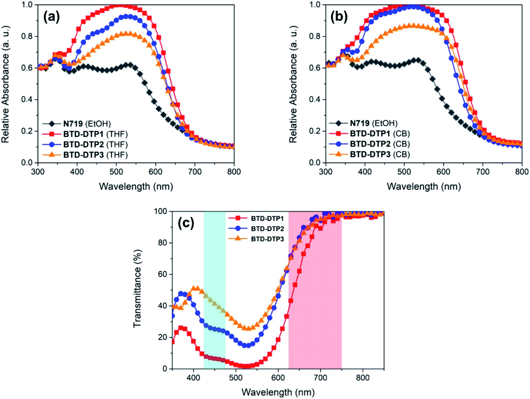 | ||
| Fig. 5 UV-Vis absorbance curves of the working electrodes of 6 μm thickness sensitized by the dyes BTD-DTP1–3 (a) in THF and (b) in chlorobenzene (CB) solution and, for comparison, by N719 in ethanol (EtOH) solution, obtained from DRS experiments. (c) Transmittance spectra of thin (5 μm) transparent TiO2 films stained with THF solutions of dyes BTD-DTP1–3. Photosynthetically active regions are coloured in cyan (425–475 nm) and red (625–750 nm). | ||
Clearly, on TiO2, the absorption peaks of the dyes were broader than in solution, but still located in the green region, at about 520 nm, while the absorption onset was found at about 700 nm, ensuring good transparency in the red portion of the visible spectrum, the most important one for the plant photoreceptors. Once again, this was in good agreement with the results of the above TD-DFT computational study. Compound BTD-DTP3 showed a wide spectral window in the blue region too, making it a suitable candidate for application to greenhouses, as confirmed by transmittance measurements (Fig. 5c). Accordingly, its WT% value of 48% (Table 2) was the highest among the three sensitizers. In the spectra of the other two dyes BTD-DTP1 and BTD-DTP2 a shoulder is present at about 430 nm, which decreased the WT% values (17% and 37%, respectively). However, their stronger absorbance along the whole visible spectrum compared to dye BTD-DTP3 suggested that they could provide DSSC devices with superior photovoltaic performances.
Interestingly, the maximum light absorptions of dyes BTD-DTP2 and BTD-DTP3 remained almost unchanged moving from solution to TiO2 adsorption, while BTD-DTP1 exhibited a hypsochromic shift of 20 nm, becoming the dye with the most blue-shifted λmax absorbance among the series. This behaviour could be due to the capability of the bulky bis-octyloxy-substituted biphenyl group of reducing the formation of H-aggregates in the solid state, which would be impossible for the smaller hexyl chain. Also, BTD-DTP3 presented the most red-shifted absorption spectrum, which could be due to the attainment of a more planar structure upon anchoring on TiO2, as shown by DFT calculations (see above, and Fig. S2†). The density of adsorbed dyes on TiO2 was then calculated by comparison with the absorbance of a standard solution of each dye in THF before and after sensitization; BTD-DTP2 and BTD-DTP3, which have similar size, showed similar densities of 1.12–1.26 × 10⁻⁷ mol cm−2, while the smaller dye BTD-DTP1 exhibited an approximately two-fold concentration (2.48 × 10⁻⁷ mol cm−2) once adsorbed on a TiO2 electrode.
Compared with THF, a more intense and broader absorption spectrum of the working electrode is attained by dissolving the dyes in CB, with the main differences to be observed in the 400–450 nm and 600–650 nm regions. Besides, a small hypsochromic shift of all absorption peaks of the dyes was observed. These results were indicative of a higher loading of dye molecules on TiO2 using CB instead of THF as a solvent, possibly accompanied by a modification of their self-organization on the semiconductor surface, as previously observed for other metal-free dyes.56,57 Interestingly, in both cases the working electrodes sensitized by the new organic dyes showed a quite higher absorbance in the visible spectrum when compared to that sensitized by the conventional N719 (Fig. 5a and b). This shows the superior characteristics of dyes BTD-DTP1–3 as sensitizers, arising from their high molar attenuation coefficients, which are more than threefold higher than that of the conventional N719 in the visible range.58
Finally, to estimate the oxidation potentials of the new dyes both at the ground and excited state, cyclic voltammograms (CV) of BTD-DTP1–3 dissolved in CHCl3 solution were recorded, using 0.1 M TBAPF6 as the supporting electrolyte and ferrocene as the external standard (see Table 2). All the new molecules exhibited quasi-reversible first oxidation peaks (CV plots are reported in Fig. S6†). Ground-state oxidation potentials (ES+/S) were comprised in the +0.96 to 1.12 V vs. NHE range, and were thus much more positive than the potentials of the most common redox shuttles used in DSSCs, such as I−/I3−.59 Excited-state oxidation potentials (ES+/S*), on the other hand, were fairly negative (−0.99 to 1.12 V vs. NHE), ensuring a sufficient overpotential for facile electron injection into the conduction band of nanocrystalline TiO2 (ECB (TiO2) = −0.5 V vs. NHE).16
Photovoltaic characterization of DSSCs built with dyes BTD-DTP1–3
Small-scale DSSCs of 0.25 cm2 active area were fabricated using the new organic dyes and then fully characterized. Different anode thicknesses were tested, starting from an optimal value of 15 μm that is usually applied in conventional ruthenium-based DSSCs for attaining high performance.60–62 Then, in view of increasing the transparency of solar cells, two other series of DSSCs employing anodes of 9 μm and 6 μm thickness were studied. The different coloured working electrodes that were sensitized with the new dyes are shown in Fig. S7,† as well as a cross-section of the resulting solar cells. For the thinnest electrodes, CB was additionally tested as a dye-adsorption solvent and the results were compared with the corresponding systems fabricated using THF. In all cases, the results were also compared to those obtained by employing the conventional N719 dye, under the same conditions. Fig. 6 shows the J–V characteristic curves of the DSSCs containing the different dyes, while their electrical characteristics are tabulated in Table 3.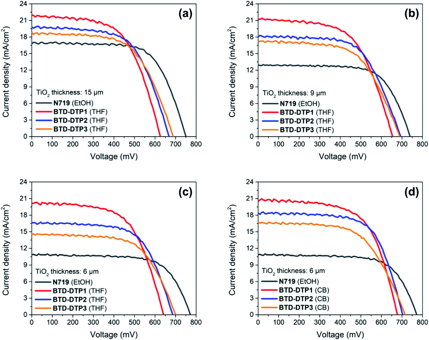 | ||
| Fig. 6 J–V curves of the solar cells that employed working electrodes of different thicknesses sensitized by organic dyes BTD-DTP1–3 as well as Ru-dye N719. (a) 15 μm, THF solution; (b) 9 μm, THF solution; (c) 6 μm, THF solution; (d) 6 μm, CB solution. | ||
| TiO2 thickness [μm] | Dye | Solvent | J SC [mA cm−2] | V OC [mV] | FF [—] | ECE [%] |
|---|---|---|---|---|---|---|
| a Values obtained as an average of the data collected on three devices and reported with the corresponding standard deviation. | ||||||
| 15 | N719 | EtOH | 16.73 ± 0.09 | 750 ± 3 | 0.68 ± 0.01 | 8.58 ± 0.02 |
| 9 | N719 | EtOH | 13.02 ± 0.06 | 740 ± 2 | 0.68 ± 0.01 | 6.52 ± 0.02 |
| 6 | N719 | EtOH | 10.92 ± 0.06 | 772 ± 2 | 0.69 ± 0.01 | 5.78 ± 0.03 |
| 15 | BTD-DTP1 | THF | 22.00 ± 0.53 | 626 ± 4 | 0.59 ± 0.02 | 8.12 ± 0.03 |
| 9 | BTD-DTP1 | THF | 21.09 ± 0.34 | 654 ± 4 | 0.59 ± 0.02 | 8.18 ± 0.04 |
| 6 | BTD-DTP1 | THF | 20.24 ± 0.32 | 642 ± 3 | 0.61 ± 0.02 | 7.88 ± 0.04 |
| 6 | BTD-DTP1 | CB | 20.55 ± 0.48 | 678 ± 3 | 0.63 ± 0.01 | 8.77 ± 0.03 |
| 15 | BTD-DTP2 | THF | 19.89 ± 0.35 | 668 ± 4 | 0.61 ± 0.02 | 8.06 ± 0.02 |
| 9 | BTD-DTP2 | THF | 18.12 ± 0.43 | 694 ± 3 | 0.62 ± 0.02 | 7.75 ± 0.03 |
| 6 | BTD-DTP2 | THF | 16.59 ± 0.27 | 686 ± 3 | 0.64 ± 0.01 | 7.28 ± 0.03 |
| 6 | BTD-DTP2 | CB | 18.41 ± 0.18 | 703 ± 2 | 0.66 ± 0.01 | 8.54 ± 0.02 |
| 15 | BTD-DTP3 | THF | 18.70 ± 0.32 | 689 ± 4 | 0.60 ± 0.02 | 7.77 ± 0.03 |
| 9 | BTD-DTP3 | THF | 17.01 ± 0.29 | 690 ± 3 | 0.60 ± 0.02 | 7.08 ± 0.03 |
| 6 | BTD-DTP3 | THF | 14.76 ± 0.39 | 700 ± 2 | 0.62 ± 0.02 | 6.37 ± 0.03 |
| 6 | BTD-DTP3 | CB | 16.55 ± 0.31 | 715 ± 2 | 0.60 ± 0.02 | 7.14 ± 0.03 |
Evidently, the solar cells built employing the BTD–DTP dyes were often better performing than those obtained with the conventional N719 dye. In the case where the solar cells were fabricated using a 15 μm-thick photoanode, the energy conversion efficiency (ECE) of BTD-DTP1, BTD-DTP2, and BTD-DTP3 was 8.12%, 8.06%, and 7.77%, respectively. These values are quite satisfactory when compared to that obtained with the conventional N719 dye under the same conditions, which was 8.58%. The slightly reduced ECE attained in the case of the organic dyes was attributed to their lower VOC and FF values, but, remarkably, they presented a consistently higher JSC compared with N719. As the thickness of the photo-anode of DSSCs was reduced first to 9 μm and then to 6 μm, the solar cells fabricated with dyes BTD-DTP1–3 still displayed very good performances, preserving a high ECE, which decreased less than 20% compared to that measured with the 15 μm-thick anode (in the worst case). In contrast, DSSCs built with N719 dye showed a larger decrease in their ECE (higher than 30%) by reducing the photo-anode thickness, mainly attributed to the fall of the JSC value, which could be ascribed to the lower molar attenuation coefficient of N719 compared to those of BTD-DTP1–3 (1.33 × 10⁴ M−1 cm−1 for N71963vs. 4.95–6.43 × 10⁴ M−1 cm−1 for BTD-DTP1–3).
The efficiency values were even higher when the devices were fabricated using CB as a dye-adsorption solvent, with the record ECE of the DSSCs reaching 8.77% with a 6 μm thickness. In particular, JSC values obtained with the dye BTD-DTP1 were higher than those recorded with the other two dyes, which is in agreement with its much higher adsorption density on TiO2, in turn linked to its smaller size (Table 2). On the other hand, VOC values were higher for dyes BTD-DTP2,3, which could be related to their structure and in particular to the bulky biphenyl substituent featured on the DTP nitrogen (see below for a detailed discussion in the context of EIS experiments).42 To the best of the authors' knowledge, the ECE values obtained here are the highest reported for dyes especially developed towards greenhouse application,7,31–33,64 and compare well with those of the best sensitizers employed in semitransparent DSSCs,65–67 considering that the latter were not designed to comply with the same stringent spectral requirements. Remarkably, the increased ECE that was reached by using CB instead of THF as a dye-adsorption solvent was clearly related to a generalized increase of all the representative parameters of the solar cells, but in particular of the photocurrents (Table 3), probably as a result of the higher amount of dyes adsorbed on TiO2 from the CB solution, as suggested by the broader and more intense light absorption profiles (see Fig. 5b). Despite the increased performances, this aspect should be carefully considered when evaluating the cell transparency requirements for application in greenhouses.
Fig. 7 shows the incident-photon-to-current-efficiency (IPCE) spectra and the corresponding integrated JSC of the DSSCs with the 6 μm anode and sensitized by the different dyes. As can be seen, the solar cells built using organic dyes showed high external quantum efficiency in the visible spectrum, much higher than that of the solar cell fabricated using the conventional dye N719, with the photo-current onset being, in most of the cases, almost at 750 nm. The maximum IPCE was achieved with BTD-DTP1 dye in DSSCs, which reached almost 80% at about 500 nm, while the BTD-DTP2 and BTD-DTP3 dyes reached 75% and 68%, respectively, in the visible spectrum. The use of CB as a dye-adsorption solvent instead of THF resulted in higher and broader IPCE spectra of the DSSCs, in agreement with the DRS results. In all cases, the external quantum efficiency of the DSSCs that employed the new organic dyes was much higher than that of the solar cell incorporating N719 dye, which did not exceed the value of 55% in the visible spectrum. This reveals the drawback of using the conventional N719 dye as a sensitizer in DSSCs employing thin photo-anodes and the superiority of our new organic dyes for the development of high-transparency solar cells. It should also be noted that the values of integrated JSC coming from the IPCE measurements were in perfect agreement with the values stemming from the J–V measurements, confirming the good accuracy of the photovoltaic characterization.
 | ||
| Fig. 7 Solid lines: IPCE curves of the solar cells that employed the working electrodes of 6 μm thickness sensitized by the different dyes. Dotted lines: Integrated short-circuit currents. (a) Sensitization from THF solution; (b) sensitization from CB solution. | ||
In the final part of this study, the charge transfer processes taking place in the solar cells were analysed by means of Electrochemical Impedance Spectroscopy (EIS).68 Measurements were performed using cells with photoanodes of 6 μm thickness sensitized by the different dyes.
The Nyquist plots and the Bode phase diagrams are shown in Fig. 8, while the parameters obtained by EIS are tabulated in Table 4. In the Nyquist plots, due to the use of a high-performance liquid state electrolyte, two semicircles were observed; the small semicircle at the higher frequencies corresponds to charge transfer processes taking place at the Pt/electrolyte interface, while the larger one at the lower frequencies arises from the charge transfer processes taking place at the TiO2/dye/electrolyte interface.
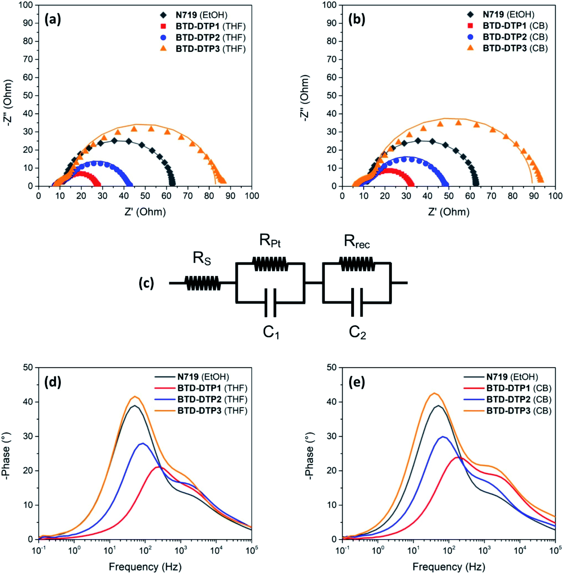 | ||
| Fig. 8 Nyquist plots (a, b), equivalent circuit used for their fitting (c), and Bode phase diagrams (d, e) for the solar cells that employed the working electrodes of 6 μm thickness sensitized by the different dyes. (a, d) Sensitization from THF solution; (b, e) sensitization from CB solution. | ||
| Dye | Solvent | R rec (ohm) | τ e (ms) |
|---|---|---|---|
| a For V = −VOC under dark conditions. | |||
| N719 | EtOH | 50 | 3.16 |
| BTD-DTP1 | THF | 15 | 0.66 |
| BTD-DTP1 | CB | 26 | 0.88 |
| BTD-DTP2 | THF | 28 | 1.89 |
| BTD-DTP2 | CB | 33 | 2.31 |
| BTD-DTP3 | THF | 68 | 3.16 |
| BTD-DTP3 | CB | 73 | 4.07 |
Several parameters can be obtained by fitting the experimental spectra with an electrochemical model (see the equivalent circuit presented in Nyquist plots), namely the series resistance of the solar cell (Rs), the charge transfer resistance at the Pt/electrolyte interface (RPt), and the charge transfer resistance at the TiO2/dye/electrolyte interface (Rrec). Here, the values of Rs and RPt were found to be comparable for all the DSSCs, reflecting the similar fabrication conditions and materials used at the counter electrode, while the values of Rrec were quite different. More specifically, the Rrec values increased in the order BTD-DTP1 < BTD-DTP2 < BTD-DTP3, both for THF and CB solutions. Such results suggest that for the latter two dyes a slower charge recombination rate is taking place at the TiO2/dye/electrolyte interface, in good agreement with their molecular structures. Indeed, it was already reported for other dyes that the bulky, alkoxy-substituted biphenyl substituent present on the DTP nitrogen might form an efficient protective layer on the semiconductor surface, resulting in an increased charge recombination lifetime compared to a simple alkyl chain, and thus in a higher VOC.42 In addition, the values obtained when the staining was performed in CB were higher than the corresponding ones using THF, that is, once again, in agreement with a higher dye adsorption density, resulting in a more compact insulating layer on TiO2, able to slow down charge recombination. Considering the Bode phase plots, the frequency of the peaks observed in the middle-frequency domain can be used to evaluate the electron lifetime within the semiconductor (τe), providing another indication of the charge recombination rate taking place at the TiO2/dye/electrolyte interface.
In agreement with the previous measurements, the τe values increased in the order BTD-DTP1 < BTD-DTP2 < BTD-DTP3, both for THF and CB as dye-adsorption solvents, while the values obtained for the devices fabricated using CB as the staining solvent were higher than the corresponding ones with THF. Electron lifetime and charge recombination rate at the TiO2/dye/electrolyte interface appear thus to be influenced by factors such as dye molecule size and geometry, and dye adsorption behaviour, resulting in a strong influence on the photo-voltage of the solar cells, in agreement with previous literature reports.69 Indeed, in the present investigation, the trend in the values of Rrec and τe found for the new BTD–DTP dyes was consistent with the values of VOC obtained for the corresponding solar cells. In contrast the higher value of VOC in the case of N719, compared with the other dyes, should be attributed to a different reason, considering that both its Rrec and τe values were intermediate between those of the BTD–DTP dyes. Indeed, for a certain electrolyte composition, differences in VOC are linked to variations in the quasi-Fermi-level of the metal oxide semiconductor, which is in turn correlated not only with the electron density at the equilibrium (depending on the rate of recombination between the semiconductor electrons and the oxidized electrolyte species), but also with the position of the semiconductor conduction band edge.16 It has been reported that, upon anchoring, charge transfer from the dyes to the semiconductor can induce a significant shift of the conduction band position, which is maximized in the case of compact dyes with a strong donating character.70N719 is a homoleptic dye connected to TiO2 through three carboxylate linkages,71 and is therefore expected to induce a higher shift in the semiconductor conduction band compared to BTD–DTP organic dyes, connected via a single carboxylic group and endowed with an additional electron-withdrawing unit, thus yielding devices characterized by a higher VOC.
Conclusions
In this work, we presented the synthesis and characterization of three new D–A–π–A organic sensitizers, specially designed to build semitransparent DSSCs with potential application in agrivoltaics. The compounds are based on an electron-withdrawing 2,1,3-benzothiadiazole core connected to an electron-rich dithieno[3,2-b:2′,3′-d]pyrrole (DTP) unit, but present different bulky side chains influencing their physico-chemical properties. Computational studies at the TD-DFT level suggested that the compounds should be able to absorb light intensely in the green part of the visible spectrum while leaving appropriate “windows” in the red and blue regions, making them suitable for the foreseen application.Assembly of the dyes' central backbone was swiftly achieved by means of Pd-catalysed direct arylation protocols, which allowed significant reduction of the number of synthetic steps and purification procedures of the intermediates compared to classic cross-coupling reactions. UV-Vis absorption and transmittance studies of the synthesized dyes both in solution and those adsorbed on TiO2 essentially confirmed the results of calculations. Fabrication of DSSC devices and measurement of their photovoltaic characteristics highlighted how the new organic dyes produced cells of comparable efficiency relative to the reference Ru-based dye N719 when employing a thick TiO2 layer, but largely overcame its performances when thinner (down to 6 μm) layers were used, making them more suitable for the fabrication of transparent devices. In addition, staining from CB solutions of the dyes was demonstrated to provide more efficient cells compared to the use of a more common solvent such as THF, probably thanks to the higher density of dye molecules adsorbed on the semiconductor surface. Under such optimized conditions, remarkable ECE values between 7.14 and 8.77% were obtained, with high photocurrents up to >20 mA cm−2. EIS studies revealed a close connection between the dye structures and the recorded photovoltages, indicating that the bulky biphenyl substituent present in dyes BTD-DTP2–3 could screen efficiently the semiconductor surface and thus reduce charge recombination rates at the TiO2/dye/electrolyte interface. Clearly, finding the right compromise between these two important properties will constitute the key to the successful development of large-area prototypes. These investigations are currently in progress and their results will be reported in due course.
Author contributions
A. D., L. Z., M. C., A. M. and G. R. conceptualized the work. A. D. and S. B. performed the synthesis and the photo-electrochemical characterization of the dyes. M. C. contributed to the NMR- and MS-characterization of the dyes. A. S. made the computational analysis. D. A. C., A. K. and E. S. fabricated and characterized the test solar devices. The manuscript was written through contributions of all authors. All authors have given approval to the final version of the manuscript.Conflicts of interest
There are no conflicts to declare.Acknowledgements
The authors thank the “Cassa di Risparmio di Pistoia e Pescia” Foundation (“FOTOSER” project, Bando “Giovani e Ricerca Scientifica”) and the Italian Ministry of University and Research (“Best4U” project, PON 2014-2020) for financial support. A. S. acknowledges MIUR Grant – Department of Excellence 2018–2022 and computational resources provided by hpc@dbcf (http://molsys.dbcf.unisi.it/hpc). Dr Jonathan Filippi (CNR-ICCOM) is acknowledged for his help in conducting the CV experiments. Mr Carlo Bartoli (CNR-ICCOM) is acknowledged for his technical support.References
- Global energy transformation: A roadmap to 2050 (2019 edition), 2019 Search PubMed.
- Q. Schiermeier, J. Tollefson, T. Scully, A. Witze and O. Morton, Nature, 2008, 454, 816 CrossRef CAS.
- REN21, Renewables 2020 Global Status Report, 2020 Search PubMed.
- A. K. Pandey, V. V. Tyagi, J. A. Selvaraj, N. A. Rahim and S. K. Tyagi, Renewable Sustainable Energy Rev., 2016, 53, 859–884 CrossRef.
- C. Dupraz, H. Marrou, G. Talbot, L. Dufour, A. Nogier and Y. Ferard, Renewable Energy, 2011, 36, 2725–2732 CrossRef.
- R. Shamshiri, F. Kalantari, K. C. Ting, K. R. Thorp, I. A. Hameed, C. Weltzien, D. Ahmad and Z. M. Shad, Int. J. Agric. Biol. Eng., 2018, 11, 1–22 Search PubMed.
- L. La Notte, L. Giordano, E. Calabrò, R. Bedini, G. Colla, G. Puglisi and A. Reale, Appl. Energy, 2020, 278, 115582 CrossRef.
- H. Marrou, J. Wery, L. Dufour and C. Dupraz, Eur. J. Agron., 2013, 44, 54–66 CrossRef.
- M. Kadowaki, A. Yano, F. Ishizu, T. Tanaka and S. Noda, Biosyst. Eng., 2012, 111, 290–297 CrossRef.
- M. Cossu, L. Murgia, L. Ledda, P. A. Deligios, A. Sirigu, F. Chessa and A. Pazzona, Appl. Energy, 2014, 133, 89–100 CrossRef.
- R. Ureña-Sánchez, Á. J. Callejón-Ferre, J. Pérez-Alonso and Á. Carreño-Ortega, Sci. Agric., 2012, 69, 233–239 CrossRef.
- J. Pérez-Alonso, M. Pérez-García, M. Pasamontes-Romera and A. J. Callejón-Ferre, Renewable Sustainable Energy Rev., 2012, 16, 4675–4685 CrossRef.
- O. Inganäs, Adv. Mater., 2018, 30, 1800388 CrossRef.
- V. V. Brus, J. Lee, B. R. Luginbuhl, S. J. Ko, G. C. Bazan and T. Q. Nguyen, Adv. Mater., 2019, 31, 1900904 CrossRef.
- J. Lee, H. Cha, H. Yao, J. Hou, Y. H. Suh, S. Jeong, K. Lee and J. R. Durrant, ACS Appl. Mater. Interfaces, 2020, 12, 32764–32770 CrossRef CAS.
- A. Hagfeldt, G. Boschloo, L. Sun, L. Kloo and H. Pettersson, Chem. Rev., 2010, 110, 6595–6663 CrossRef CAS.
- A. Fakharuddin, R. Jose, T. M. Brown, F. Fabregat-Santiago and J. Bisquert, Energy Environ. Sci., 2014, 7, 3952–3981 RSC.
- L. Lu, M. E. Ya'acob, M. S. Anuar, G. Chen, M. H. Othman, A. Noor Iskandar and N. Roslan, Energy Reports, 2020, 6, 238–253 CrossRef.
- G. K. Ntinas, K. Kadoglidou, N. Tsivelika, K. Krommydas, A. Kalivas, P. Ralli and M. Irakli, Horticulturae, 2019, 5, 42 CrossRef.
- K. Zhang, C. Qin, X. Yang, A. Islam, S. Zhang, H. Chen and L. Han, Adv. Energy Mater., 2014, 4, 1301966 CrossRef.
- M. Godfroy, J. Liotier, V. M. Mwalukuku, D. Joly, Q. Huaulmé, L. Cabau, C. Aumaitre, Y. Kervella, S. Narbey, F. Oswald, E. Palomares, C. A. Gonzàlez Flores, G. Oskam and R. Demadrille, Sustainable Energy Fuels, 2021, 5, 144–153 RSC.
- N. Roslan, M. E. Ya'acob, D. Jamaludin, A. N. Iskandar and M. H. Othman, AIP Conf. Proc., 2019, 2129, 1–6 Search PubMed.
- A. Listorti, B. O'Regan and J. R. Durrant, Chem. Mater., 2011, 23, 3381–3399 CrossRef CAS.
- K. Inada, Plant Cell Physiol., 1976, 17, 355–365 Search PubMed.
- K. J. McCree, Agric. Meteorol., 1971, 9, 191–216 CrossRef.
- C. S. Brown, A. C. Schuerger and J. C. Sager, J. Am. Soc. Hortic. Sci., 1995, 120, 808–813 CAS.
- C. J. M. Emmott, J. A. Röhr, M. Campoy-Quiles, T. Kirchartz, A. Urbina, N. J. Ekins-Daukes and J. Nelson, Energy Environ. Sci., 2015, 8, 1317–1328 RSC.
- H. Shi, R. Xia, G. Zhang, H. L. Yip and Y. Cao, Adv. Energy Mater., 2019, 9, 1–8 Search PubMed.
- Y. Liu, P. Cheng, T. Li, R. Wang, Y. Li, S.-Y. Chang, Y. Zhu, H.-W. Cheng, K.-H. Wei, X. Zhan, B. Sun and Y. Yang, ACS Nano, 2019, 13, 1071–1077 CrossRef CAS.
- F. Yang, Y. Zhang, Y. Hao, Y. Cui, W. Wang, T. Ji, F. Shi and B. Wei, Appl. Opt., 2015, 54, 10232–10239 CrossRef CAS.
- J. J. Kim, M. Kang, O. K. Kwak, Y. J. Yoon, K. S. Min and M. J. Chu, Int. J. Photoenergy, 2014, 2014, 376315 Search PubMed.
- N. Duvva, D. Raptis, C. V. Kumar, E. N. Koukaras, L. Giribabu and P. Lianos, Dyes Pigm., 2016, 134, 472–479 CrossRef CAS.
- A. Dessì, M. Calamante, A. Sinicropi, M. L. Parisi, L. Vesce, P. Mariani, B. Taheri, M. Ciocca, A. Di Carlo, L. Zani, A. Mordini and G. Reginato, Sustainable Energy Fuels, 2020, 4, 2309–2321 RSC.
- J. M. Ji, H. Zhou and H. K. Kim, J. Mater. Chem. A, 2018, 6, 14518–14545 RSC.
- Y. Wu, W. H. Zhu, S. M. Zakeeruddin and M. Grätzel, ACS Appl. Mater. Interfaces, 2015, 7, 9307–9318 CrossRef CAS.
- Y. Wu, M. Marszalek, S. M. Zakeeruddin, Q. Zhang, H. Tian, M. Grätzel and W. Zhu, Energy Environ. Sci., 2012, 5, 8261–8272 RSC.
- X. Zhang, Y. Xu, F. Giordano, M. Schreier, N. Pellet, Y. Hu, C. Yi, N. Robertson, J. Hua, S. M. Zakeeruddin, H. Tian and M. Grätzel, J. Am. Chem. Soc., 2016, 138, 10742–10745 CrossRef CAS.
- Y. K. Eom, I. T. Choi, S. H. Kang, J. Lee, J. Kim, M. J. Ju and H. K. Kim, Adv. Energy Mater., 2015, 5, 1500300 CrossRef.
- S. H. Kang, M. J. Jeong, Y. K. Eom, I. T. Choi, S. M. Kwon, Y. Yoo, J. Kim, J. Kwon, J. H. Park and H. K. Kim, Adv. Energy Mater., 2017, 7, 1602117 CrossRef.
- J. M. Ji, H. Zhou, Y. K. Eom, C. H. Kim and H. K. Kim, Adv. Energy Mater., 2020, 10, 2000124 CrossRef CAS.
- H. Zhou, J. M. Ji, S. H. Kang, M. S. Kim, H. S. Lee, C. H. Kim and H. K. Kim, J. Mater. Chem. C, 2019, 7, 2843–2852 RSC.
- N. Cai, J. Zhang, M. Xu, M. Zhang and P. Wang, Adv. Funct. Mater., 2013, 23, 3539–3547 CrossRef CAS.
- M. J. Frisch, G. W. Trucks, H. B. Schlegel, G. E. Scuseria, M. A. Robb, J. R. Cheeseman, G. Scalmani, V. Barone, G. A. Petersson, H. Nakatsuji, X. Li, M. Caricato, A. V. Marenich, J. Bloino, B. G. Janesko, R. Gomperts, B. Mennucci, H. P. Hratchian, J. V. Ortiz, A. F. Izmaylov, J. L. Sonnenberg, D. Williams-Young, F. Ding, F. Lipparini, F. Egidi, J. Goings, B. Peng, A. Petrone, T. Henderson, D. Ranasinghe, V. G. Zakrzewski, J. Gao, N. Rega, G. Zheng, W. Liang, M. Hada, M. Ehara, K. Toyota, R. Fukuda, J. Hasegawa, M. Ishida, T. Nakajima, Y. Honda, O. Kitao, H. Nakai, T. Vreven, K. Throssell, J. A. Montgomery Jr, J. E. Peralta, F. Ogliaro, M. J. Bearpark, J. J. Heyd, E. N. Brothers, K. N. Kudin, V. N. Staroverov, T. A. Keith, R. Kobayashi, J. Normand, K. Raghavachari, A. P. Rendell, J. C. Burant, S. S. Iyengar, J. Tomasi, M. Cossi, J. M. Millam, M. Klene, C. Adamo, R. Cammi, J. W. Ochterski, R. L. Martin, K. Morokuma, O. Farkas, J. B. Foresman and D. J. Fox, Gaussian 16, Revision C.01, Gaussian, Inc., Wallingford CT, 2016 Search PubMed.
- M. J. Lundqvist, M. Nilsing, P. Persson and S. Lunell, Int. J. Quantum Chem., 2006, 106, 3214–3234 CrossRef CAS.
- M. Guo, R. He, Y. Dai, W. Shen, M. Li, C. Zhu and S. H. Lin, J. Phys. Chem. C, 2012, 116, 9166–9179 CrossRef CAS.
- J. Wang, M. Li, D. Qi, W. Shen, R. He and S. H. Lin, RSC Adv., 2014, 4, 53927–53938 RSC.
- M. Paramasivam, R. K. Chitumalla, S. P. Singh, A. Islam, L. Han, V. Jayathirtha Rao and K. Bhanuprakash, J. Phys. Chem. C, 2015, 119, 17053–17064 CrossRef CAS.
- A. Dessì, A. Sinicropi, S. Mohammadpourasl, R. Basosi, M. Taddei, F. Fabrizi De Biani, M. Calamante, L. Zani, A. Mordini, P. Bracq, D. Franchi and G. Reginato, ACS Omega, 2019, 4, 7614–7627 CrossRef.
- Y. Xie, W. Wu, H. Zhu, J. Liu, W. Zhang, H. Tian and W.-H. Zhu, Chem. Sci., 2016, 7, 544–549 RSC.
- F. Li, Y. Chen, X. Zong, W. Qiao, H. Fan, M. Liang and S. Xue, J. Power Sources, 2016, 332, 345–354 CrossRef CAS.
- M.-L. Han, Y.-Z. Zhu, S. Liu, Q.-L. Liu, D. Ye, B. Wang and J.-Y. Zheng, J. Power Sources, 2018, 387, 117–125 CrossRef CAS.
- P.-P. Dai, Y.-Z. Zhu, Q.-L. Liu, Y.-Q. Yan and J.-Y. Zheng, Dyes Pigm., 2020, 175, 108099 CrossRef CAS.
- P.-Y. Ho, Y. Wang, S.-C. Yiu, W.-H. Yu, C.-L. Ho and S. Huang, Org. Lett., 2017, 19, 1048–1051 CrossRef CAS.
- M. Velusamy, K. R. Justin Thomas, J. T. Lin, Y.-C. Hsu and K.-C. Ho, Org. Lett., 2005, 7, 1899–1902 CrossRef CAS.
- M. L. Parisi, A. Dessì, L. Zani, S. Maranghi, S. Mohammadpourasl, M. Calamante, A. Mordini, R. Basosi, G. Reginato and A. Sinicropi, Front. Chem., 2020, 8, 214 CrossRef CAS.
- Y. Wang, L. Yang, J. Zhang, R. Li, M. Zhang and P. Wang, ChemPhysChem, 2014, 15, 1037–1042 CrossRef CAS.
- L. Zhang and J. M. Cole, J. Mater. Chem. A, 2017, 5, 19541–19559 RSC.
- M. K. Nazeeruddin, S. M. Zakeeruddin, R. Humphry-Baker, M. Jirousek, P. Liska, N. Vlachopoulos, V. Shklover, C.-H. Fischer and M. Grätzel, Inorg. Chem., 1999, 38, 6298–6305 CrossRef CAS.
- G. Boschloo and A. Hagfeldt, Acc. Chem. Res., 2009, 42, 1819–1826 CrossRef CAS.
- Y. Yan, J. Wang, Q. Chang, M. Babikier, H. Wang, H. Li, Q. Yu, S. Gao and S. Jiao, Electrochim. Acta, 2013, 94, 277–284 CrossRef CAS.
- Z. S. Wang, H. Kawauchi, T. Kashima and H. Arakawa, Coord. Chem. Rev., 2004, 248, 1381–1389 CrossRef CAS.
- D. A. Chalkias, D. I. Giannopoulos, E. Kollia, A. Petala, V. Kostopoulos and G. C. Papanicolaou, Electrochim. Acta, 2018, 271, 632–640 CrossRef CAS.
- P. J. Holliman, M. Mohsen, A. Connell, M. L. Davies, K. Al-Salihi, M. B. Pitak, G. J. Tizzard, S. J. Coles, R. W. Harrington, W. Clegg, C. Serpa, O. H. Fontes, C. Charbonneaue and M. J. Carniee, J. Mater. Chem., 2012, 22, 13318–13327 RSC.
- N. Roslan, M. E. Ya'acob, M. A. M. Radzi, Y. Hashimoto, D. Jamaludin and G. Chen, Renewable Sustainable Energy Rev., 2018, 92, 171–186 CrossRef.
- X. Xie, D. Sun, Y. Wei, Y. Yuan, J. Zhang, Y. Ren and P. Wang, J. Mater. Chem. A, 2019, 7, 11338–11346 RSC.
- H. Wu, J. Zhang, Y. Ren, Y. Zhang, Y. Yuan, Z. Shen, S. Li and P. Wang, ACS Appl. Energy Mater., 2020, 3, 4549–4558 CrossRef CAS.
- Y. Ren, Y. Cao, D. Zhang, S. M. Zakeeruddin, A. Hagfeldt, P. Wang and M. Grätzel, Adv. Mater., 2020, 32, 2000193 CrossRef CAS.
- A. Sacco, Renewable Sustainable Energy Rev., 2017, 79, 814–829 CrossRef CAS.
- A. Dessì, M. Calamante, A. Mordini, M. Peruzzini, A. Sinicropi, R. Basosi, F. Fabrizi De Biani, M. Taddei, D. Colonna, A. Di Carlo, G. Reginato and L. Zani, RSC Adv., 2015, 5, 32657–32668 RSC.
- E. Ronca, M. Pastore, L. Belpassi, F. Tarantelli and F. De Angelis, Energy Environ. Sci., 2013, 6, 183–193 RSC.
- F. De Angelis, S. Fantacci, A. Selloni, M. Grätzel and M. K. Nazeeruddin, Nano Lett., 2007, 7, 3189–3195 CrossRef CAS.
Footnote |
| † Electronic supplementary information (ESI) available: Additional figures concerning the synthesis and the spectroscopic and electrochemical characterization of compounds BTD-DTP1–3, copies of the 1H- and 13C-NMR spectra of compounds 3, 4, 6, 8, BTD-DTP1–3. See DOI: 10.1039/d0se01610a |
| This journal is © The Royal Society of Chemistry 2021 |