 Open Access Article
Redox-active zinc thiolates for low-cost aqueous rechargeable Zn-ion batteries†
Madison R.
Tuttle‡
a,
Christopher
Walter‡
a,
Emma
Brackman
a,
Curtis E.
Moore
a,
Matthew
Espe
b,
Chris
Rasik
b,
Paul
Adams
b and
Shiyu
Zhang
 *a
*a
aDepartment of Chemistry and Biochemistry, The Ohio State University, 100 W. 18th Ave, Columbus, OH 43210, USA. E-mail: zhang.8941@osu.edu
bLubrizol Corporation, 29400 Lakeland Blvd, Wickliffe, OH, USA
First published on 10th November 2021
Abstract
Aqueous zinc-ion batteries (AZIBs) are promising candidates for large-scale electrical energy storage due to the inexpensive, safe, and non-toxic nature of zinc. One key area that requires further development is electrode materials that store Zn2+ ions with high reversibility and fast kinetics. To determine the viability of low-cost organosulfur compounds as OEMs for AZIBs, we investigate how structural modification affects electrochemical performance in Zn-thiolate complexes 1 and 2. Remarkably, modification of one thiolate in 1 to sulfide in 2 reduces the voltage hysteresis from 1.04 V to 0.15 V. While 1 exhibits negligible specific capacity due to the formation of insulating DMcT polymers, 2 delivers a capacity of 107 mA h g−1 with a primary discharge plateau at 1.1 V vs. Zn2+/Zn. Spectroscopic studies of 2 suggest a Zn2+ and H+ co-insertion mechanism with Zn2+ as the predominant charge carrier. Capacity fading in Zn-2 cells likely results from the formation of (i) soluble H+ insertion products and (ii) non-redox-active side products. Increasing electrolyte concentration and using a Nafion membrane significantly enhances the stability of 2 by suppressing H+ insertion. Our findings provide insight into the molecular design strategies to reduce the polarization potential and improve the cycling stability of the thiolate/disulfide redox couple in aqueous battery systems.
Introduction
Increasing demand for electrical energy combined with mounting environmental concerns over the use of fossil fuels has spurred interest in generating electrical energy from renewable resources. Electrical energy production from wind, solar, and water sources is naturally intermittent; therefore, large-scale, low-cost energy storage systems are necessary to compensate for this variability.1 Conventional electrical energy storage systems, such as non-aqueous Li-ion batteries, have high energy densities and long cycle lifetimes, but their application in grid-scale energy storage is limited by the low natural abundance of lithium resources and potential safety hazards of flammable organic electrolytes.2,3 Ideally, future large-scale energy storage systems should move beyond Li-ion batteries toward more sustainable, safer alternatives.Aqueous zinc-ion batteries (AZIBs) are considered one of the most promising candidates for large-scale energy storage due to (i) the low cost, high capacity (820 mA h g−1), and low toxicity of the Zn anode, (ii) the high ionic conductivity and safety of aqueous electrolytes, and (iii) the ease of manufacturing due to the stability of the Zn anode to ambient conditions.4,5 One of the key research areas for progressing AZIBs toward grid-scale electrical energy storage applications is the development of compatible cathode materials. The majority of reported AZIB cathodes are inorganic materials, e.g., metal oxides, Prussian blue analogs, and others.4–12 Many of these materials have rigid lattices that can impede reversible Zn2+ (de)insertion, resulting in poor electrochemical kinetics (i.e., sluggish ion diffusion and charge transfer) or irreversible lattice deformation. In contrast, organic electrode materials (OEMs) often have flexible solid-state structures that can easily accommodate reversible (de)insertion of multivalent cations, e.g., Zn2+ and Al3+, through lattice reorganization.8,13–16 Furthermore, OEMs are more sustainable and structurally diverse compared to inorganic cathode materials.
State-of-the-art OEMs are based on quinone/phenazine moieties in AZIBs (Fig. 1A), which are often expensive to purchase or synthesize, limiting their practical use in large-scale energy storage.4,5,8,17–23 To address this issue, we are interested in exploring other redox-active organic compounds beyond quinones/phenazines for use as OEMs in AZIB applications. Organosulfur compounds are especially promising, as they are highly cost-effective. In particular, 2,5-dimercapto-1,3,4-thiadiazole (DMcT, Fig. 1A) is an exceptionally inexpensive organosulfur starting material ($0.86 per gram) for many antiwear/anticorrosion lubricant additives.24 In Li-ion batteries, DMcT performs poorly as a cathode material due to the low conductivity and sluggish redox kinetics of disulfide-based electro(de)polymerization. As a result, Li-ion batteries with DMcT cathodes often require heating or the addition of electrocatalysts in order to achieve acceptable cycling performance.25–29 Some modifications to DMcT have shown promise in improving its electrochemical behavior. For example, Buttry and coworkers found that deprotonation of the thiol moieties in DMcT and replacement of one thiol/thiolate moiety with a non-redox-active group produced more reversible redox behavior in non-aqueous electrolytes.30 Furthermore, work by Oyama et al. showed that complexation with Lewis acidic metal ions like Cu2+ increases the conductivity of DMcT-based solid-state electrodes, facilitating DMcT electro(de)polymerization and improving electrode current densities.31–33
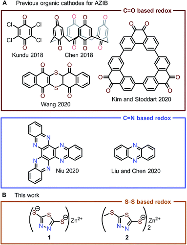 | ||
| Fig. 1 (A) State-of-the-art organic cathode materials for AZIBs are mostly based on the redox of quinone/phenazine. (B) Zn-thiolate cathode materials reported in this work. | ||
With the intention to fundamentally understand and improve the electrochemical behavior of DMcT for AZIB applications, we combine the benefits of previously established synthetic modifications and metal ion complexation in Zn2+-DMcT complexes 1 and 2 (Fig. 1A). To determine how these structural modifications impact voltage polarization and cycle stability, we investigate the electrochemical performance of 1 and 2 as OEMs in AZIBs. Spectroscopic analysis coupled with pH-dependent studies of the best performing OEM 2 shows a predominantly Zn2+-based (de)insertion mechanism followed by minor H+ (de)insertion. The gradual capacity decay in Zn-2 cells likely results from the formation of (i) soluble thiol 5-(methylthio)-1,3,4-thiadiazole-2-thiol (4) via H+ insertion and (ii) non-redox-active 2,5-bis(methylthio)-1,3,4-thiadiazole (5) via a proposed redox-induced methyl shift reaction. Optimization of the Zn-2 system with a concentrated Zn2+ electrolyte and a Nafion membrane inhibits H+ insertion and significantly improves capacity retention. Our study illustrates the viability of the thiolate/disulfide redox couple in AZIBs and provides practical methods for optimizing the performance of organosulfur OEMs.
Result and discussion
Synthesis and characterization of DMcT derivatives 1–3
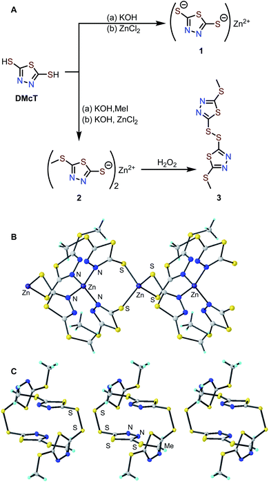
Zn complexes of 2,5-dimercapto-1,3,4-thiadiazole (1) and 5-(methylthio)-1,3,4-thiadiazole-2-thiol (2) were prepared by treating the corresponding potassium salts with an aqueous solution of ZnCl2 (Fig. 2A).34 The Zn-thiolate complexes form as easily isolable precipitates, and elemental analysis of complexes 1 and 2 is consistent with the corresponding empirical formulas (see ESI†). The solid-state structures of 1 and 2 were investigated by powder X-ray diffraction (PXRD). While the PXRD of 1 shows poor crystallinity (Fig. S4†), that of 2 exhibits many sharp diffraction peaks suitable for structure determination. The PXRD pattern of 2 indicates an I4 space group with lattice parameters of a = b = 18.137 Å, c = 8.710 Å, and the diffraction pattern matches the simulated pattern obtained from the single-crystal X-ray diffraction data of 2 (Fig. S5†).35 The crystal structure contains two Zn sites coordinated by either four N atoms (Zn–N distance: 2.036 Å) or four S atoms (Zn–S distance: 2.355 Å) in tetrahedral geometries. The ZnN4 and ZnS4 units are arranged alternately to afford a one-dimensional coordination polymer (Fig. 2B).To elucidate the redox mechanism of 2, the oxidation product of 2 was independently isolated by chemical oxidation with H2O2 to afford the corresponding disulfide (3) in 32% yield. Single crystals suitable for XRD analysis were obtained by slow evaporation of an ethyl acetate solution of 3. Single-crystal XRD analysis shows molecules of 3 pack in a P1 bar space group with lattice parameters of a = 7.7086, b = 8.5728, c = 9.4538, α = 85.498°, β = 86.274°, γ = 80.635° (Fig. 2C and S7†). Based on the unit cells of 2 and 3, the removal of Zn2+ causes a ca. 14% volume contraction.
Solid-state cyclic voltammetry study
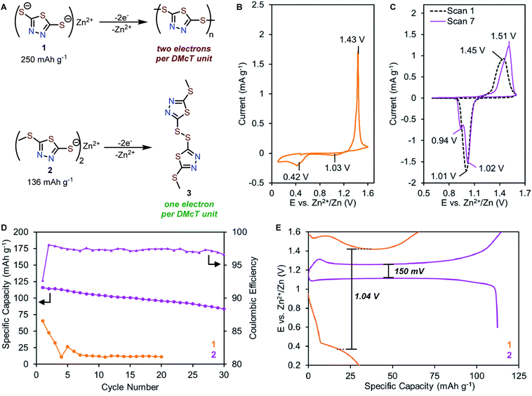
Compounds 1 and 2 feature similar thiolate functional groups that are expected to form disulfide bonds upon oxidation at 1.1–1.4 V vs. Zn2+/Zn.30–32 Compound 1 is known to undergo oxidation to form a mixture of dimers, oligomers, and polymers. Complete electropolymerization of 1 requires a total of two electrons per DMcT unit (Fig. 3A, top), affording a high theoretical capacity of 250 mA h g−1. In contrast, compound 2 is unable to undergo electropolymerization since one redox-active thiolate is synthetically blocked. The oxidation of 2 generates disulfide 3 as the only product, affording a theoretical capacity of 136 mA h g−1 (Fig. 3A, bottom).The electrochemical properties of 1 and 2 in the solid-state were evaluated in coin-type cells with a Zn metal anode, Zn-thiolate cathode, and 1 M ZnSO4 as the electrolyte. The solid-state CV of 1 shows a single oxidation peak at 1.43 V vs. Zn2+/Zn (Fig. 3B), corresponding to the oxidation of 1 to a mixture of dimers, oligomers, and polymers. The reverse scan reveals two reduction peaks at 1.03 V and 0.42 V (Fig. 3B), which are assigned to the reduction of DMcT dimer and DMcT oligomer/polymer, respectively.27–31,36 The 1.01 V redox polarization of 1 indicates poor electrochemical kinetics, which renders 1 impractical for energy storage applications.
By comparison, the CV of 2 shows a broad oxidation peak at 1.45 V followed by a reduction peak at 1.01 V, suggesting 2 undergoes a simple thiolate/disulfide redox mechanism (Fig. 3C). As 2 can only form dimers upon electrochemical oxidation, the voltage hysteresis is significantly reduced by 0.57 V compared to 1. In subsequent scans, the primary redox couple of 2 shifts anodically, and a second reduction peak gradually appears at 0.94 V (Fig. 3C, purple trace). This observation suggests that 2 has a more complex electrochemical mechanism, which will be discussed in detail below.
Preliminary galvanostatic cycling experiments
To elucidate how molecular modification affects the cycling performance of 1 and 2, galvanostatic charge–discharge (GCD) experiments were performed at a rate of 0.5C (125 mA g−1 for 1, 68 mA g−1 for 2) with voltage cut-offs selected based on solid-state CV studies. Zn-1 cells deliver initial capacities of only 66 mA h g−1, corresponding to 26% of theoretical values (Fig. 3D and S9†). The cell capacity quickly fades to <5% after five cycles. Similar to the CV study, the GCD profile of 1 exhibits a charge plateau at ca. 1.42 V and a sloping discharge plateau at ca. 0.34 V with a high voltage hysteresis of 1.04 V (Fig. 3E and S9†). In contrast, Zn-2 cells achieve a specific capacity of 116 mA h g−1, which decays over 30 cycles to 72% of the initial capacity with an average coulombic efficiency of 97% (Fig. 3D and S10†). The Zn-2 cells exhibit a single charge plateau at 1.26 V and a primary discharge plateau at 1.10 V with a small voltage hysteresis of 150 mV (Fig. 3E). Interestingly, a secondary discharge plateau can be seen at ca. 1.0 V (Fig. S10†), consistent with the appearance of a second peak in later CV scans.Primary redox mechanism of 2 in AZIB
The emergence of a new reduction peak/plateau suggests the development of a secondary redox process, prompting further investigation into the redox mechanism of 2. First, we utilized ex situ X-ray fluorescence spectroscopy (XRF) to quantify the amount of Zn in fully charged or discharged samples of 2. After charging, the Zn content in 2 is reduced to <30% of pristine values (from 1035 to 289 counts per second, Fig. 4B green trace and S18†), indicating that most of the Zn2+ ions are extracted from the cathode material during oxidation. After discharging, the Zn content returns to pristine values (1046 counts per second, red trace), indicating Zn2+ insertion occurs during reduction. The significant variation of Zn content in the cathode material reveals that Zn2+ is a predominant charge carrier in thiolate/disulfide redox.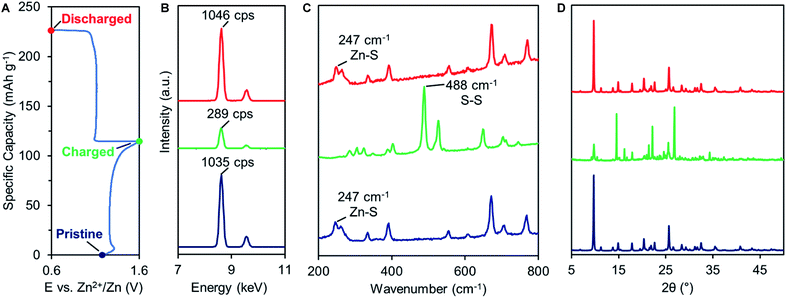 | ||
| Fig. 4 (A) Typical GCD profile of 2. Ex situ (B) XRF, (C) Raman, and (D) PXRD analysis of pristine (blue), charged (green), and discharged (red) 2. | ||
Raman spectroscopy was also performed on charged and discharged samples of 2 to identify the primary redox-active species during cycling (Fig. 4C). Upon charging, the Zn–S vibrational feature at 247 cm−1 disappears while a new S–S vibrational feature emerges at 488 cm−1, indicating Zn2+ deinsertion and formation of disulfide 3. The S–S vibrational assignment was confirmed using a pristine sample of 3, prepared by chemical oxidation (Fig. S19†). Upon discharge, the Zn–S vibration returns while the S–S vibration disappears. The Raman spectrum of charged 2 was compared to that of ZnSO4 to evaluate a potential SO42− (de)insertion mechanism. The signature SO42− Raman signals (1022, 1071, 1081 cm−1) are not observed in the charged sample, indicating that SO42− does not participate as a charge carrier (Fig. S19 and 20†).
The Zn2+-based (de)insertion mechanism was further verified by ex situ PXRD and SEM analysis (Fig. 4D, S5 and 6†). After the first cycle, charged 2 exhibits a PXRD pattern nearly identical to the pristine sample of disulfide 3, while discharged 2 retains the PXRD pattern of pristine 2. After 60 cycles, discharged 2 exhibits a slightly broader PXRD pattern compared to pristine 2 (Fig. S5†), suggesting a morphological change may have occurred during cycling. We utilized SEM to assess the morphology of pristine and cycled electrodes of 2. Pristine 2 shows an irregular particle morphology that transforms into star-shaped crystals after 60 charge–discharge cycles (Fig. S6†). Morphology changes are common for organic electrode materials and are likely due to the disruption caused by ion insertion/desertion and volume change. Taken together, these studies suggest that the primary redox mechanism for 2 is the formation/breaking of the disulfide bond accompanied by Zn2+ (de)insertion (Fig. 5A, top). Given that Zn2+ is the predominant charge carrier, the discharge plateau at 1.10 V likely corresponds to Zn2+ insertion. However, understanding the mechanism of the secondary discharge plateau at 1.0 V could provide insight into the gradual capacity decay observed in Zn-2 cells.
Evaluating proton (de)insertion mechanism in 2
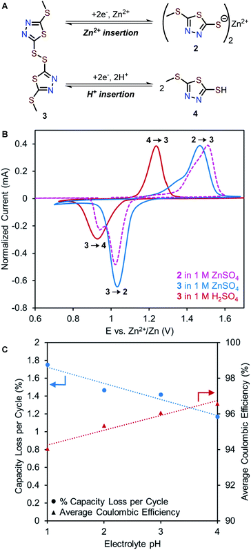
While the most common and widely accepted AZIB mechanism involves the reversible (de)insertion of Zn2+, co-insertion of Zn2+ and H+ is also possible, as observed in many metal oxide cathode materials (e.g., MnO2, and NaV3O8·1.5H2O)37–39 and recently in quinone- and phenazine-based OEMs.22,40 Given the acidic nature of 1 M ZnSO4 (pH 4.39), both Zn2+ and H+ could potentially serve as charge carriers in the redox of 2. Proton insertion should afford 5-(methylthio)-1,3,4-thiadiazole-2-thiol (4, Fig. 5A, bottom).To evaluate a potential H+ (de)insertion mechanism, three-electrode solid-state CV studies were performed using either 1 M ZnSO4 or 1 M H2SO4 as the electrolyte. The working electrode was prepared with disulfide 3 to avoid biasing which ion was (de)inserted (Fig. 5A). The CV graph in 1 M H2SO4 is adjusted to pH = 4 based on the Nernst equation to represent the mildly acidic environment of 1 M ZnSO4 (Fig. 5B and S8†). The first reduction peak in the solid-state CV of 2 in 1 M ZnSO4 (pink trace) aligns with the reduction of 3 in 1 M ZnSO4 (blue trace), confirming Zn2+ insertion (3 to 2) occurs at 1.03 V. Meanwhile, the second reduction peak in the solid-state CV of 2 (pink trace) aligns with the reduction of 3 in 1 M H2SO4 (red trace), suggesting H+ insertion (3 to 4) occurs at 0.95 V. Furthermore, galvanostatic intermittent titration technique (GITT) was employed to determine the diffusion coefficients for each redox process (see ESI†). As Zn2+ is larger than H+, the diffusion coefficient for Zn2+ insertion is expected to be slower than that of H+ insertion.38,41 The diffusion coefficients were determined to be 3.94 × 10⁻¹¹ cm2 s−1 for Zn2+ insertion ( and 1.31 × 10⁻⁹ cm2 s−1 for H+ insertion (Fig. S13†). These CV and GITT experiments support the existence of a primary Zn2+ (de)insertion mechanism at ca. 1.0–1.1 V and a secondary H+ (de)insertion mechanism at ca. 0.9–1.0 V.
To investigate the effects of H+ insertion on the cycling stability of 2, pH-dependent galvanostatic cycling studies were conducted using coin cells of 2 at 0.2C (27 mA g−1). The degree of H+ (de)insertion is expected to increase as the electrolyte becomes more acidic, leading to higher capacity contribution of the H+ plateau. Interestingly, the capacity contribution due to H+ insertion remains at ca. 20 mA h g−1 per cycle regardless of pH (Fig. S11†). Meanwhile, the overall capacity diminishes faster with lower coulombic efficiency as the concentration of H+ increases (Fig. 5C). For example, Zn-2 cells with pH = 4 electrolyte exhibit a 1.17% capacity loss per cycle and an average coulombic efficiency of 96.6%, while cells with pH = 1 electrolyte exhibit a 1.75% capacity loss per cycle and an average coulombic efficiency of 94.0% (Fig. 5C and S12†). Collectively, these experiments indicate that increasing the H+ concentration of the electrolyte is detrimental to the cycling performance. We hypothesize this effect can be explained by the formation of 4 in acidic electrolytes, which could have a higher solubility than 2 due to its low molecular weight and hydrophilicity.23
Mechanism of capacity fading
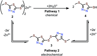
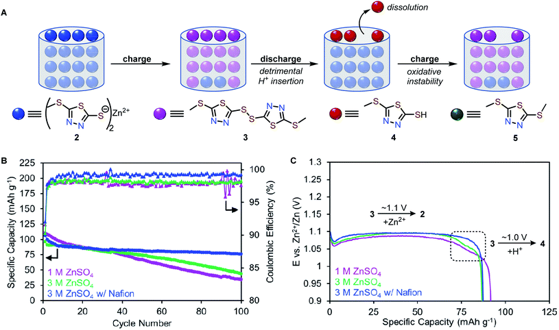
The conversion of 2 to 4 can occur via two pathways (Scheme 1). Pathway 1 involves hydrolysis of 2 to afford 4, which is a process that does not involve electrochemistry. Pathway 2 involves electrochemical conversion from 2 to 4via3, which is consistent with the secondary discharge plateau at 1.0 V (vide supra). We found that 2 does not dissolve in protic solvents in any measurable quantity, likely due to its polymeric solid-state structure. Therefore, the formation of 4via Pathway 1 is assumed to be negligible, leaving electrochemical Pathway 2 as the active mechanism for the conversion of 2 to 4.Next, we evaluate the relative solubility of pristine samples of 3 and 4 in aqueous electrolytes using UV-vis spectroscopy. Stirring 3 and 4 in a 1 M ZnSO4 solution for 30 minutes results in the formation of new bands around 306 and 297 nm, respectively, indicating the dissolution of 3 and 4 in the electrolyte (Fig. S22†). Assuming the same extinction coefficients in aqueous ZnSO4 solutions and 1 M Zn(OTf)2 in MeOH (ε = 1.07 × 10⁴ M−1 cm−1 for 3 and 1.02 × 10⁴ M−1 cm−1 for 4, Fig. S21–23†), the concentrations of 3 and 4 were calculated to be 0.044 mM and 7.7 mM, respectively (Fig. S22†). These experiments confirm that 4 is the most soluble redox-active species in aqueous electrolytes, and if formed, it can contribute to substantial capacity fading.
We propose a possible series of events that accounts for the capacity decay of 2 (Fig. 6A). Upon charging, Zn2+ deinserts from Zn-thiolate 2 to form disulfide 3. Upon discharging, Zn2+ inserts to most interior thiolate sites. Since the terminal thiolate sites cannot provide a tetrahedral environment for Zn2+ to coordinate, these sites preferentially undergo H+ insertion to form 4. Because compound 4 has a higher solubility than other redox-active species, partial dissolution of 4 occurs during each cycle, which is responsible for the capacity decay and low coulombic efficiency observed in Zn-2 cells.
Mechanism-driven optimization of Zn-2 cells
We hypothesize that preventing the dissolution of 4 can improve the cycling stability of Zn-2 cells. We found that the solubility of 4 is decreased by three-fold from 7.7 mM to 2.4 mM in 3 M ZnSO4 (Fig. S22†). Galvanostatic cycling studies at a rate of 1C (136 mA g−1) in 3 M ZnSO4 show the capacity retention improves from 31% (in 1 M ZnSO4) to 45% over 100 cycles and the average coulombic efficiency of 2 increases from 97.9% (in 1 M ZnSO4) to 98.1%, and (Fig. 6B, S14 and 15†). The H+ insertion plateau still exists at ca. 1.0 V in 3 M ZnSO4, but the capacity contribution is reduced (10 mA h g−1) compared to cells in 1 M ZnSO4 electrolyte (20 mA h g−1, Fig. 6C and S15†). The reduced proton insertion likely stems from a nearly two-fold increase of Zn2+ ions compared to H+ (Table S3†).Encouraged by the improved stability in 3 M ZnSO4 electrolyte, we theorized that increasing the Zn2+ conductivity would further enhance cycling stability. The use of Nafion in AZIBs has been shown to enhance Zn2+ ion conductivity.42,43 Indeed, coin cells of 2 with Nafion and 3 M ZnSO4 electrolyte show the best cycling performance, achieving a specific capacity of 107 mA h g−1 with 71% capacity retention over 100 cycles and an average coulombic efficiency of 99% (Fig. 6B and S16†). Notably, the H+ insertion plateau is absent in Zn-2 cells with Nafion (Fig. 6C blue trace), suggesting that increasing Zn2+ ion conductivity suppresses H+ insertion (Fig. 6C and S16†). Under the optimized conditions, variable-rate cycling studies of Zn-2 cells shows capacities of ca. 75 mA h g−1 at 3C (408 mA g−1 Fig. S16†). While the cycling performance was significantly improved, Zn-2 cells still exhibit a 0.4% capacity loss per cycle, perhaps due to the intrinsic chemical instability of 2 during cycling.
Chemical instability of 2
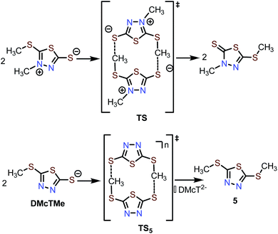
During post-mortem analysis of Zn-2 cells, a noticeable stench was detected, indicating the formation of volatile S-containing compounds. Various cell components, e.g., cathode and anode, were extracted with CH2Cl2 and analyzed by GC-MS (Fig. S24 and 25†). Both cathode and anode contain a decomposition product with m/z = 178, which can be assigned to dimethylated DMcT (5, Scheme 2). Since pristine 2 and 3 do not decay to 5 in the electrolyte, it is reasonable to hypothesize that formation of 5 is induced during thiolate/disulfide redox. Interestingly, methyl shifting has been observed for an analogous DMcT derivative (Scheme 2, top), which proceeds through a bimolecular transition state TS.44 The formation of 5 could proceed through a similar transition state TS5, which involves the bimolecular interaction of two DMcTMe motifs (Scheme 2, bottom). In this case, a neutral (two radical DMcTMe motifs, n = 0) or monoanionic (one radical DMcTMe motif and one anionic DMcTMe motif, n = ˙−) transition state would be favored over a dianionic (two anionic DMcTMe motifs, n = 2−) transition state, as the coulombic repulsion between the two DMcTMe motifs would be significantly reduced. This could explain why decomposition to 5 is triggered by the oxidation of the DMcTMe anion (Fig. 6A). We are currently designing new Zn-thiolate complexes that would be more resilient toward such a methyl shift decomposition process.Conclusion
In summary, our study describes the first application of a thiolate/disulfide-based redox mechanism in AZIBs. Electrochemical studies show that 1 exhibits irreversible electropolymerization, similar to parent DMcT, suggesting that complexation with Lewis acidic Zn2+ does little to improve electrochemical behavior. However, methylation of one thiolate group in 1 to sulfide in 2 leads to a significant reduction of voltage hysteresis from 1.04 V to 0.15 V, enabling the application of DMcT in AZIB. Investigation of the redox mechanism of 2 reveals that both Zn2+ and H+ insertion occurs, but Zn2+ is the predominant charge carrier. Detailed spectroscopic studies indicate that capacity decay in Zn-2 cells likely stems from the formation of (i) soluble thiol 4via H+ insertion and (ii) non-redox-active 5via a proposed redox-induced methyl shift. Importantly, the formation and dissolution of 4 can be inhibited by high concentrations of Zn2+ and the use of a Nafion membrane. Our work highlights the importance of synthetic modification and mechanistic investigation as tools for systematically improving the electrochemical behavior of OEMs. Furthermore, our study demonstrates the viability of the thiolate/disulfide redox couple in AZIB applications, providing a new redox platform for the design of next-generation OEMs for sustainable energy storage.Experimental section
All synthetic procedures were carried out under nitrogen (or argon) atmosphere using an MBraun glovebox and/or standard Schlenk techniques unless stated otherwise. 1H and 13C NMR spectra were recorded on Bruker 400 MHz spectrometer and were externally referenced to the NMR residual solvent peaks. ATR-IR spectra were measured using a Nicolet IR 200 with a diamond ATR accessory. The pH was measured using an Oakton pH 5+ handheld meter. Zn-thiolate cathode powders were prepared by milling a 70![[thin space (1/6-em)]](https://www.rsc.org/images/entities/char_2009.gif) :
:![[thin space (1/6-em)]](https://www.rsc.org/images/entities/char_2009.gif) 20
20![[thin space (1/6-em)]](https://www.rsc.org/images/entities/char_2009.gif) :
:![[thin space (1/6-em)]](https://www.rsc.org/images/entities/char_2009.gif) 10 mixture of active material, carbon black (Super P), and PVDF (polyvinylidene fluoride) binder, which was used directly in coin cell fabrication. Because the initial electrochemical behavior is known to be significantly different due to reorganization of the crystal lattice in OEMs,45,46 we performed a single galvanostatic cycle at 0.5C (Fig. S9 and 10†) prior to cyclic voltammetry (CV) experiments. Cyclic voltammetry experiments were performed with a Biologic SP-150 single-channel potentiostat. Galvanostatic cycling experiments were performed with a LAND CT2001A battery testing system. Raman spectra were measured using a Renishaw Raman IR microprobe with a 514 nm laser beam. X-ray fluorescence (XRF) spectra were measured by an Olympus/Innov-X X-5000 XRF analyzer with a tantalum X-ray tube source and a silicon drift detector. Unless otherwise noted, all solvents were degassed and dried using a Pure Process Technology (PPT) solvent purification system and stored under an atmosphere of nitrogen over 4 Å molecular sieves. DMSO-d6 (Cambridge Isotope Labs) was dried over CaH2 and vacuum transferred onto 4 Å molecular sieves prior to use. CDCl3 (Cambridge Isotope Labs) was degassed by three freeze–pump–thaw cycles and stored over 4 Å molecular sieves prior to use. All glassware were dried at 175 °C before use. All reagents were purchased from Sigma Aldrich unless otherwise noted.
10 mixture of active material, carbon black (Super P), and PVDF (polyvinylidene fluoride) binder, which was used directly in coin cell fabrication. Because the initial electrochemical behavior is known to be significantly different due to reorganization of the crystal lattice in OEMs,45,46 we performed a single galvanostatic cycle at 0.5C (Fig. S9 and 10†) prior to cyclic voltammetry (CV) experiments. Cyclic voltammetry experiments were performed with a Biologic SP-150 single-channel potentiostat. Galvanostatic cycling experiments were performed with a LAND CT2001A battery testing system. Raman spectra were measured using a Renishaw Raman IR microprobe with a 514 nm laser beam. X-ray fluorescence (XRF) spectra were measured by an Olympus/Innov-X X-5000 XRF analyzer with a tantalum X-ray tube source and a silicon drift detector. Unless otherwise noted, all solvents were degassed and dried using a Pure Process Technology (PPT) solvent purification system and stored under an atmosphere of nitrogen over 4 Å molecular sieves. DMSO-d6 (Cambridge Isotope Labs) was dried over CaH2 and vacuum transferred onto 4 Å molecular sieves prior to use. CDCl3 (Cambridge Isotope Labs) was degassed by three freeze–pump–thaw cycles and stored over 4 Å molecular sieves prior to use. All glassware were dried at 175 °C before use. All reagents were purchased from Sigma Aldrich unless otherwise noted.
Funding
This work was supported in part through Lubrizol Corporation, Ralph E. Powe Junior Faculty Enhancement Award by Oak Ridge Associated Universities, the National Science Foundation Graduate Research Fellowship under Grant No. DGE-1343012, the National Science Foundation under CBET-2124604, the Sustainability Institute at Ohio State University, and the Center for Emergent Materials, NSF MRSEC, under award number DMR-2011876.Data availability
Crystallographic data for 3 has been deposited at the CCDC. Data for this paper, including experimental details, synthetic procedures, electrochemical details, crystallographic details, and Fig. S1–S25 are available at ESI.†Author contributions
The manuscript was written by MRT, CW, and SZ. MRT and CW contributed equally. All authors have given approval to the final version of the manuscript.Conflicts of interest
A provisional patent has been filed under the names of S. Z., M. R. T., C. R., and P. A. All other authors declare no competing interests.Acknowledgements
The authors would like to the Wade and McGrier laboratories for ATR-IR, Dr Alicia Friedman for HRMS, Drs Tanya Whitmer and Dan Conroy for NMR, Tyler Weaver for XRF, and Dr Barbara Dunlap for Raman.References
- Z. Yang, J. Zhang, M. C. W. Kintner-Meyer, X. Lu, D. Choi, J. P. Lemmon and J. Liu, Electrochemical Energy Storage for Green Grid, Chem. Rev., 2011, 111, 3577–3613 CrossRef CAS PubMed.
- A. Manthiram, Materials Challenges and Opportunities of Lithium Ion Batteries, J. Phys. Chem. Lett., 2011, 2, 176–184 CrossRef CAS.
- A. Manthiram, An Outlook on Lithium Ion Battery Technology, ACS Cent. Sci., 2017, 3, 1063–1069 CrossRef CAS PubMed.
- L. Chen, Q. An and L. Mai, Recent Advances and Prospects of Cathode Materials for Rechargeable Aqueous Zinc-Ion Batteries, Adv. Mater. Interfaces, 2019, 6, 1900387 CrossRef.
- B. Tang, L. Shan, S. Liang and J. Zhou, Issues and Opportunities Facing Aqueous Zinc-Ion Batteries, Energy Environ. Sci., 2019, 12, 3288–3304 RSC.
- Z. Rong, R. Malik, P. Canepa, G. Sai Gautam, M. Liu, A. Jain, K. Persson and G. Ceder, Materials Design Rules for Multivalent Ion Mobility in Intercalation Structures, Chem. Mater., 2015, 27, 6016–6021 CrossRef CAS.
- H. Glatz, E. Lizundia, F. Pacifico and D. Kundu, An Organic Cathode Based Dual-Ion Aqueous Zinc Battery Enabled by a Cellulose Membrane, ACS Appl. Energy Mater., 2019, 2, 1288–1294 CrossRef CAS.
- D. Kundu, P. Oberholzer, C. Glaros, A. Bouzid, E. Tervoort, A. Pasquarello and M. Niederberger, Organic Cathode for Aqueous Zn-Ion Batteries: Taming a Unique Phase Evolution toward Stable Electrochemical Cycling, Chem. Mater., 2018, 30, 3874–3881 CrossRef CAS.
- C. Xia, J. Guo, Y. Lei, H. Liang, C. Zhao and H. N. Alshareef, Rechargeable Aqueous Zinc-Ion Battery Based on Porous Framework Zinc Pyrovanadate Intercalation Cathode, Adv. Mater., 2018, 30, 1705580 CrossRef PubMed.
- F. Ming, H. Liang, Y. Lei, S. Kandambeth, M. Eddaoudi and H. N. Alshareef, Layered MgXV2O5·nH2O as Cathode Material for High-Performance Aqueous Zinc Ion Batteries, ACS Energy Lett., 2018, 3, 2602–2609 CrossRef CAS.
- K. W. Nam, S. S. Park, R. dos Reis, V. P. Dravid, H. Kim, C. A. Mirkin and J. F. Stoddart, Conductive 2D Metal–Organic Framework for High-Performance Cathodes in Aqueous Rechargeable Zinc Batteries, Nat. Commun., 2019, 10, 4948 CrossRef PubMed.
- Y. Ru, S. Zheng, H. Xue and H. Pang, Layered V-MOF Nanorods for Rechargeable Aqueous Zinc-Ion Batteries, Mater. Today Chem., 2021, 21, 100513 CrossRef CAS.
- M. Walter, K. V. Kravchyk, C. Böfer, R. Widmer and M. V. Kovalenko, Polypyrenes as High-Performance Cathode Materials for Aluminum Batteries, Adv. Mater., 2018, 30, 1705644 CrossRef PubMed.
- B. Pan, J. Huang, Z. Feng, L. Zeng, M. He, L. Zhang, J. T. Vaughey, M. J. Bedzyk, P. Fenter, Z. Zhang, A. K. Burrell and C. Liao, Polyanthraquinone-Based Organic Cathode for High-Performance Rechargeable Magnesium-Ion Batteries, Adv. Energy Mater., 2016, 6, 1600140 CrossRef.
- I. A. Rodríguez-Pérez, Y. Yuan, C. Bommier, X. Wang, L. Ma, D. P. Leonard, M. M. Lerner, R. G. Carter, T. Wu, P. A. Greaney, J. Lu and X. Ji, Mg-Ion Battery Electrode: An Organic Solid's Herringbone Structure Squeezed upon Mg-Ion Insertion, J. Am. Chem. Soc., 2017, 139, 13031–13037 CrossRef PubMed.
- D. J. Kim, D. J. Yoo, M. T. Otley, A. Prokofjevs, C. Pezzato, M. Owczarek, S. J. Lee, J. W. Choi and J. F. Stoddart, Rechargeable Aluminium Organic Batteries, Nat. Energy, 2019, 4, 51–59 CrossRef CAS.
- Z. Guo, Y. Ma, X. Dong, J. Huang, Y. Wang and Y. Xia, An Environmentally Friendly and Flexible Aqueous Zinc Battery Using an Organic Cathode, Angew. Chem., Int. Ed., 2018, 57, 11737–11741 CrossRef CAS PubMed.
- G. Dawut, Y. Lu, L. Miao and J. Chen, High-Performance Rechargeable Aqueous Zn-Ion Batteries with a Poly(Benzoquinonyl Sulfide) Cathode, Inorg. Chem. Front., 2018, 5, 1391–1396 RSC.
- Q. Zhao, W. Huang, Z. Luo, L. Liu, Y. Lu, Y. Li, L. Li, J. Hu, H. Ma and J. Chen, High-Capacity Aqueous Zinc Batteries Using Sustainable Quinone Electrodes, Sci. Adv., 2018, 4, eaao1761 CrossRef PubMed.
- B. Häupler, C. Rössel, A. M. Schwenke, J. Winsberg, D. Schmidt, A. Wild and U. S. Schubert, Aqueous Zinc–Organic Polymer Battery with a High Rate Performance and Long Lifetime, NPG Asia Mater., 2016, 8, 283 CrossRef.
- Y. Ma, X. Xie, R. Lv, B. Na, J. Ouyang and H. Liu, Nanostructured Polyaniline-Cellulose Papers for Solid-State Flexible Aqueous Zn-Ion Battery, ACS Sustainable Chem. Eng., 2018, 6, 8697–8703 CrossRef CAS.
- Z. Tie, L. Liu, S. Deng, D. Zhao and Z. Niu, Proton Insertion Chemistry of a Zinc–Organic Battery, Angew. Chem., Int. Ed., 2020, 59, 4920–4924 CrossRef CAS PubMed.
- Q. Wang, Y. Liu and P. Chen, Phenazine-Based Organic Cathode for Aqueous Zinc Secondary Batteries, J. Power Sources, 2020, 468, 228401 CrossRef CAS.
- D.-P. Wei, L. Cao and L.-L. Wang, An Investigation into the Antiwear, Antioxidation, and Anticorrosion Behaviour of Some Derivatives of 2,5-Dimercapto-1,3,4-Thiadiaxole, Lubr. Sci., 1995, 7, 365–377 CrossRef CAS.
- Y. Liang, Z. Tao and J. Chen, Organic Electrode Materials for Rechargeable Lithium Batteries, Adv. Energy Mater., 2012, 2, 742–769 CrossRef CAS.
- M. Liu, S. J. Visco and L. C. De Jonghe, Electrode Kinetics of Organodisulfide Cathodes for Storage Batteries, J. Electrochem. Soc., 1990, 137, 750–759 CrossRef CAS.
- S. Picart and E. Geniès, Electrochemical Study of 2,5-Dimercapto-1,3,4-Thiadiazole in Acetonitrile, J. Electroanal. Chem., 1996, 408, 53–60 CrossRef.
- N. Oyama, T. Tatsuma, T. Sato and T. Sotomura, Dimercaptan–Polyaniline Composite Electrodes for Lithium Batteries with High Energy Density, Nature, 1995, 373, 598–600 CrossRef CAS.
- Y. Kiya, G. R. Hutchison, J. C. Henderson, T. Sarukawa, O. Hatozaki, N. Oyama and H. D. Abruña, Elucidation of the Redox Behavior of 2,5-Dimercapto-1,3,4-Thiadiazole (DMcT) at Poly(3,4-Ethylenedioxythiophene) (PEDOT)-Modified Electrodes and Application of the DMcT–PEDOT Composite Cathodes to Lithium/Lithium Ion Batteries, Langmuir, 2006, 22, 10554–10563 CrossRef CAS PubMed.
- E. Shouji and D. A. Buttry, A Mechanistic Study of the Influence of Proton Transfer Processes on the Behavior of Thiol/Disulfide Redox Couples, J. Phys. Chem. B, 1999, 103, 2239–2247 CrossRef CAS.
- N. Oyama, J. M. Pope and T. Sotomura, Effects of Adding Copper(ii) Salt to Organosulfur Cathodes for Rechargeable Lithium Batteries, J. Electrochem. Soc., 1997, 144, L47–L51 CrossRef CAS.
- T. Sotomura, T. Tatsuma and N. Oyama, An Organosulfur Polymer Cathode with a High Current Capability for Rechargeable Batteries, J. Electrochem. Soc., 1996, 143, 3152–3157 CrossRef CAS.
- N. Oyama and O. Hatozaki, New Composite Cathodes for Lithium Rechargeable Batteries, Mol. Cryst. Liq. Cryst. Sci. Technol., Sect. A, 2000, 349, 329–334 CrossRef CAS.
- S. Shi, T. J. Katz, B. V. Yang and L. Liu, Use of Thiazyl Chlorides, Alkyl Carbamates, and Thionyl Chloride To Fuse 1,2,5-Thiadiazoles to Quinones and To Oxidize, Chlorinate, and Aminate Them, J. Org. Chem., 1995, 60, 1285–1297 CrossRef CAS.
- J. Zhang, X. Ma, W. Kong, F. Xie, S. Yuan, X. Song, Z. Lu and X. Xuan, A Sulfur Coordination Polymer with Wide Bandgap Semiconductivity Formed from Zinc(ii) and 5-Methyl-Sulfanyl-1,3,4-Thia-Diazole-2-Thione, Acta Crystallogr., Sect. C: Struct. Chem., 2019, 75, 1243–1249 CrossRef CAS PubMed.
- J. M. Pope, T. Sato, E. Shoji, N. Oyama, K. C. White and D. A. Buttry, Organosulfur/Conducting Polymer Composite Cathodes, J. Electrochem. Soc., 2002, 149, A939 CrossRef CAS.
- X. Jia, C. Liu, Z. G. Neale, J. Yang and G. Cao, Active Materials for Aqueous Zinc Ion Batteries: Synthesis, Crystal Structure, Morphology, and Electrochemistry, Chem. Rev., 2020, 120, 7795–7866 CrossRef CAS PubMed.
- W. Sun, F. Wang, S. Hou, C. Yang, X. Fan, Z. Ma, T. Gao, F. Han, R. Hu, M. Zhu and C. Wang, Zn/MnO2 Battery Chemistry With H+ and Zn2+ Coinsertion, J. Am. Chem. Soc., 2017, 139, 9775–9778 CrossRef CAS PubMed.
- F. Wan, L. Zhang, X. Dai, X. Wang, Z. Niu and J. Chen, Aqueous Rechargeable Zinc/Sodium Vanadate Batteries with Enhanced Performance from Simultaneous Insertion of Dual Carriers, Nat. Commun., 2018, 9, 1656 CrossRef PubMed.
- Y. Wang, C. Wang, Z. Ni, Y. Gu, B. Wang, Z. Guo, Z. Wang, D. Bin, J. Ma and Y. Wang, Binding Zinc Ions by Carboxyl Groups from Adjacent Molecules toward Long-Life Aqueous Zinc–Organic Batteries, Adv. Mater., 2020, 32, 2000338 CrossRef CAS PubMed.
- T. Wu and W. Lin, Boosting Proton Storage in Layered Vanadium Oxides for Aqueous Zinc-ion Batteries, Electrochim. Acta, 2021, 394, 139134 CrossRef CAS.
- M. Ghosh, V. Vijayakumar and S. Kurungot, Dendrite Growth Suppression by Zn2+-Integrated Nafion Ionomer Membranes: Beyond Porous Separators toward Aqueous Zn/V2O5 Batteries with Extended Cycle Life, Energy Technol., 2019, 7, 1–10 CrossRef.
- M. Ghosh, V. Vijayakumar, B. Anothumakkool and S. Kurungot, Nafion Ionomer-Based Single Component Electrolytes for Aqueous Zn/MnO2 Batteries with Long Cycle Life, ACS Sustainable Chem. Eng., 2020, 8, 5040–5049 CrossRef CAS.
- A. Espinosa, R. García, P. Molina and A. Tárraga, Unexpected Transalkylation on 3-Alkyl-2-Alkylthio-1,3,4-Thiadiazolium-5-Thiolates: A Computational and Experimental Mechanistic Study, Org. Biomol. Chem., 2010, 8, 1623–1628 RSC.
- M. Lee, J. Hong, J. Lopez, Y. Sun, D. Feng, K. Lim, W. C. Chueh, M. F. Toney, Y. Cui and Z. Bao, High-Performance Sodium–Organic Battery by Realizing Four-Sodium Storage in Disodium Rhodizonate, Nat. Energy, 2017, 2, 861–868 CrossRef CAS.
- Z. Wei, D. Wang, X. Yang, C. Wang, G. Chen and F. Du, From Crystalline to Amorphous: An Effective Avenue to Engineer High-Performance Electrode Materials for Sodium-Ion Batteries, Adv. Mater. Interfaces, 2018, 5, 1800639 CrossRef.
Footnotes |
| † Electronic supplementary information (ESI) available. CCDC 2095600. For ESI and crystallographic data in CIF or other electronic format see DOI: 10.1039/d1sc04231a |
| ‡ Madison R. Tuttle and Christopher Walter contributed equally to this work. |
| This journal is © The Royal Society of Chemistry 2021 |

