
 Open Access Article
 This Open Access Article is licensed under a Creative Commons Attribution-Non Commercial 3.0 Unported Licence
Supramolecular photocatalysts fixed on the inside of the polypyrrole layer in dye sensitized molecular photocathodes: application to photocatalytic CO2 reduction coupled with water oxidation†
Fazalurahman
Kuttassery‡
 a,
Hiromu
Kumagai
b,
Ryutaro
Kamata
a,
Yusuke
Ebato
a,
Masanobu
Higashi
c,
Hajime
Suzuki
d,
Ryu
Abe
d and
Osamu
Ishitani
*a
a,
Hiromu
Kumagai
b,
Ryutaro
Kamata
a,
Yusuke
Ebato
a,
Masanobu
Higashi
c,
Hajime
Suzuki
d,
Ryu
Abe
d and
Osamu
Ishitani
*a
aDepartment of Chemistry, Tokyo Institute of Technology, 2-12-1-NE-1, O-okayama, Meguro-ku, Tokyo 152-8550, Japan. E-mail: ishitani@chem.titech.ac.jp
bInstitute of Multidisciplinary Research for Advanced Materials, Tohoku University, 2-1-1, Katahira, Aoba-ku, Sendai, Miyagi 980-8577, Japan
cThe OCU Advanced Research Institute for Natural Science and Technology, Osaka City University, 3-3-138 Sugimoto, Sumiyoshi-ku, Osaka City, Osaka 558-8585, Japan
dDepartment of Energy and Hydrocarbon Chemistry, Graduate School of Engineering, Kyoto University, Katsura, Nishikyo-ku, Kyoto 615-8510, Japan
First published on 15th September 2021
Abstract
The development of systems for photocatalytic CO2 reduction with water as a reductant and solar light as an energy source is one of the most important milestones on the way to artificial photosynthesis. Although such reduction can be performed using dye-sensitized molecular photocathodes comprising metal complexes as redox photosensitizers and catalyst units fixed on a p-type semiconductor electrode, the performance of the corresponding photoelectrochemical cells remains low, e.g., their highest incident photon-to-current conversion efficiency (IPCE) equals 1.2%. Herein, we report a novel dye-sensitized molecular photocathode for photocatalytic CO2 reduction in water featuring a polypyrrole layer, [Ru(diimine)3]2+ as a redox photosensitizer unit, and Ru(diimine)(CO)2Cl2 as the catalyst unit and reveal that the incorporation of the polypyrrole network significantly improves reactivity and durability relative to those of previously reported dye-sensitized molecular photocathodes. The irradiation of the novel photocathode with visible light under low applied bias stably induces the photocatalytic reduction of CO2 to CO and HCOOH with high faradaic efficiency and selectivity (even in aqueous solution), and the highest IPCE is determined as 4.7%. The novel photocathode is coupled with n-type semiconductor photoanodes (CoOx/BiVO4 and RhOx/TaON) to construct full cells that photocatalytically reduce CO2 using water as the reductant upon visible light irradiation as the only energy input at zero bias. The artificial Z-scheme photoelectrochemical cell with the dye-sensitized molecular photocathode achieves the highest energy conversion efficiency of 8.3 × 10⁻²% under the irradiation of both electrodes with visible light, while a solar to chemical conversion efficiency of 4.2 × 10⁻²% is achieved for a tandem-type cell using a solar light simulator (AM 1.5, 100 mW cm−2).
Introduction
The reduction of CO2 to useful carbon resources using sunlight as the energy source and water as the electron donor is expected to provide a sustainable solution to the energy and environmental problems currently facing our society.1,2 In this regard, photocatalytic CO2 reduction systems with transition metal complexes acting as (i) redox photosensitizers that absorb visible light to initiate electron transfer and (ii) catalysts that accept electrons from redox photosensitizers to reduce CO2 have drawn much attention, as these complexes exhibit tunable visible light absorption and redox properties as well as high CO2 reduction selectivity.3,4 For example, a mixed system comprising [Ru(bpy)3]2+ (bpy = 2,2′-bipyridine) as the redox photosensitizer and [Ru(X2bpy)(CO)2Cl2] as the catalyst efficiently and selectively catalyses the photoreduction of CO2 in the presence of sacrificial electron donors such as 1-benzyl-1,4-dihydronicotinamide to give CO and HCOOH, the ratio of which can be controlled by changing the reaction conditions such as solution pH and bpy substituents (X).5–7 Despite the abundance of photocatalytic systems that comprise only metal complexes and can efficiently promote the photoreduction of CO2 in the presence of sacrificial electron donors, these systems cannot use water as an electron donor owing to their relatively low oxidation power and the difficulty of the four-electron oxidation of two water molecules. However, in order to be practical, photocatalytic CO2 utilization systems should inevitably employ water as an electron donor owing to its low cost and abundance.8Hybrid systems that comprise metal complexes as (photo)catalysts and semiconductor materials and feature excited states with oxidation powers sufficient to oxidize water to O2 and/or H2O2 have been actively investigated to mitigate the above problem.9–11 Most of such hybrid systems are photoelectrochemical cells featuring a photocathode for CO2 reduction and a photoanode for water oxidation, with the sequential excitation of these photoelectrodes endowing them with strong reduction and oxidation powers.8 Such photoelectrochemical cells, also known as artificial Z-scheme cells, can be broadly classified into two groups, both of which feature n-type semiconductor photoanodes (e.g., CoOx-deposited BiVO4 (ref. 12) and reduced SrTiO3 (ref. 13)) for water oxidation. In the first group, the photocathode comprises a metal complex that is deposited on a visible-light-responsive semiconductor material and acts a CO2 reduction catalyst but does not absorb light, i.e., light is absorbed only by the semiconductor electrode (Scheme 1a).13–15 The systems of the second group feature dye-sensitized molecular photocathodes consisting of a p-type semiconductor and a supramolecular photocatalyst with redox photosensitizer and catalyst units connected to each other (Scheme 1b).10–12 The redox photosensitizer unit absorbs light and then transfers an electron from the valence band of the p-type semiconductor to the catalyst unit, which reduces CO2. The hole produced in the valence band of the p-type semiconductor is filled with an electron from the n-type semiconductor photoanode, which photochemically draws up electrons from water. Therefore, in these systems, the p-type semiconductor does not absorb light, which is their largest difference from the systems of the first group. As the two systems differ in their requirements for metal complexes and semiconductor materials, one expects a broad range of suitable complexes and materials as well as construction methods. Despite the availability of photoelectrochemical cells that promote CO2 photoreduction using water as an electron donor and visible light as an energy source, their performance metrics, especially the efficiency of light energy to chemical energy conversion, are still low.
 | ||
| Scheme 1 Two types of photocathodes for photoelectrochemical CO2 reduction. (a) Systems comprising a p-type semiconductor as the light absorbing unit and a metal complex as the catalyst. (b) Systems with dye-sensitized molecular photocathodes comprising a redox photosensitizer as the light absorbing unit, a metal complex as the catalyst, and a p-type semiconductor as the electron relay. VB = valence band, CB = conduction band. | ||
Although the photoelectrochemical systems of the second group are very rare examples of the use of molecular photocatalysts for CO2 reduction coupled with water oxidation,10–12 these systems can potentially employ various redox photosensitizers with strong absorption in the visible region, which is advantageous for visible-light-driven photocathode construction. The dye-sensitized molecular photocathodes16,17 initially reported by Meyers et al.18,19 and our groups9–11 featured metal complex-based photocatalysts with anchoring groups such as –COOH and –PO3H2 adsorbed on the electrode surface. In these systems, the photosensitizer units are only monomolecularly adsorbed on the electrode, and the visible light absorption abilities of such dye-sensitized molecular photocathodes are therefore very low. In addition, the rapid detachment of the metal complex-based photocatalysts from the electrode due to weak immobilization via anchoring groups results in low photocathode durability.20–23 As the absorption ability of a single photosensitizer molecule is not high, the number of photosensitizer units on the p-type semiconductor electrode should be increased to elevate the corresponding light absorption ability.
The methods of overcoming these bottlenecks can be broadly classified into two main types. On the one hand, one can introduce a protective metal oxide layer by atomic layer deposition to increase the durability of the dye-sensitized molecular photocathode by suppressing the detachment of metal complexes with anchoring groups.24–26 However, this approach does not increase the visible light absorption of the photocathode. Methods of the second type rely on the introduction of a polymer layer, e.g., Meyers'19 and our12,27 groups employed the reductive electropolymerization of vinyl groups in the diimine ligands of metal complexes to afford a polymer layer that contained both the photosensitizer and catalyst units on the semiconductor electrode and, compared to the photoelectrode with only the anchoring groups described above, more strongly absorbed visible light owing to the accumulation of photosensitizer units.19,27–32 The reductive electropolymerization of molecular complexes on the dye-sensitized molecular photocathode also drastically suppressed the desorption of metal complexes from the electrode and enhanced the durability of photocatalysts for CO2 reduction.19,27 However, the dye-sensitized molecular photocathodes prepared via the reductive polymerization of vinyl groups required a relatively negative applied potential to achieve maximal photocurrent, and the photocurrent density remained low, probably because of the low conductivity of the saturated hydrocarbon chains formed by vinyl group polymerization. As a result, the incident photon-to-current conversion efficiencies (IPCEs) were 1.2% or less.12 A photoelectrochemical cell comprising the dye-sensitized molecular photocathode fabricated by the reductive polymerization of vinyl groups and a CoOx/BiVO4 photoanode was reported as the most robust photocatalytic system for CO2 reduction with water without any external bias, with the photoenergy conversion efficiency (ECE) reaching 1.7 × 10⁻²%.12
The replacement of saturated hydrocarbon chains in photocathodes with conductive polymers is a promising way of reducing polymer layer resistance and increasing the efficiency of the dye-sensitized molecular photocathode. In this regard, pyrrole and its derivatives have attracted much attention owing to their high oxidative polymerization ability, relatively mild polymerization conditions, synthetic versatility, and the high conductivity of the produced polypyrrole films.28,29,33–35 Functional polypyrrole films containing metal complex units have been reported for various applications, e.g., catalytic reactions, sensors, and drug delivery.28,29,33–41 Deronzier et al. reported that a system with a polypyrrole layer containing a Re(I) complex catalyst on Pt electrodes showed higher durability for electrocatalytic CO2 reduction than the system with the corresponding mononuclear Re(I) complex in solution.33,36,42 Morikawa et al. deposited a polypyrrole layer containing a Ru(II) complex catalyst onto a p-type semiconductor photoelectrode, i.e., used a method of the first type according to the abovementioned classification.14,43–46 However, the construction of dye-sensitized molecular photocathodes with conducting polypyrrole for combining redox photosensitizer molecules and a p-type semiconductor electrode has not been reported so far.
Herein, we prepare new dye-sensitized molecular photocathodes via the formation of polypyrrole films containing both the photosensitizer and catalytic metal complexes on NiO electrodes and systematically investigate the molecular design of metal complex monomers with pyrrole groups as well as oxidative polymerization methods to develop the most efficient dye-sensitized molecular photocathode for CO2 reduction (maximum IPCE = 4.7%). The developed photocathode is combined with two n-type semiconductor photoanodes (CoOx/BiVO4 and RhOx/TaON) for water oxidation to develop systems for the photoelectrocatalytic reduction of CO2 with water using visible light as the only energy input, and the maximum ECE is determined as 8.3 × 10⁻²%.
Results and discussion
Optimization of redox photosensitizer layer on electrodes
Initially, we attempted to develop suitable polymerization methods for Ru(II) complexes with pyrrole groups on the NiO electrode, for which two types of Ru(II) trisdiimine complexes containing one or two diimine ligand(s) with two pyrrole groups, that is, 4,4′-bis((1H-pyrrol-1-yl)methyl)-2,2′-bipyridine ligand (Pyrbpy), were synthesized (PyrRu and Pyr2Ru in Scheme 2). The cyclic voltammograms of these complexes recorded under Ar in acetonitrile (MeCN) containing 0.1 M Et4NBF4 are shown in Fig. S1a and S1c,† respectively. In the case of PyrRu, one reversible and one irreversible oxidation wave were observed at Eox1/2 = 0.86 V and Eoxp = 1.19 V vs. Ag/AgNO3, respectively; the former was attributed to the one-electron oxidation of the central Ru(II) to Ru(III), as that of [Ru(dmb)3]2+ (dmb = 4,4′-dimethyl-2,2′-bipyridine) is observed at Eox1/2 = 0.77 V,47 and the latter was attributed to the oxidation of pyrrole groups. On the other hand, the cyclic voltammogram of Pyr2Ru featured only one broad large oxidation wave at Eoxp = 1.00 V, which was attributed to the combination of Ru(II) → Ru(III) oxidation and pyrrole group oxidation. These results suggest that the oxidative polymerization of the pyrrole groups of Pyr2Ru and PyrRu may proceed at a potential more positive than ∼1 V. Both cyclic voltammograms recorded at negative potentials featured three reversible reduction waves attributable to the stepwise one-electron reduction of the diimine ligands of the Ru complexes as reported earlier (Fig. S1b and S1d†).47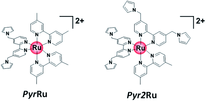 | ||
| Scheme 2 Molecular structures of Ru sensitizers (PyrRu and Pyr2Ru) containing the Pyrbpy ligand(s). | ||
A NiO nanoparticle-modified transparent fluorine-doped tin oxide (FTO) electrode was prepared by the previously reported squeeze method9,10 and used as the working electrode for the oxidative electropolymerization (induced by 25 or 50 potential sweeps between E = 0 and +1.35 V vs. Ag/AgNO3) of Ru(II) complexes with pyrrole groups. Fig. 1a shows the I–V curves of PyrRu recorded for 25 sequential potential sweeps, revealing that the current increased with increasing sweep number. The cyclic voltammogram of the electrode after 25 sweeps (Fig. 1b) indicated that 8.2 nmol cm−2 of electrochemically active Ru complexes was immobilized on NiO, with the difference between the maxima of oxidation and reduction waves (ΔE) equaling 51 mV. The polymerization of metal complexes initiated by the oxidation of pyrrole group(s) should initiate the binding of Ru(II) complexes through C–C bond formation between the pyrrole groups, and the propagation of this process should generate a polypyrrole layer containing Ru(II)trisdiimine complex units on the electrode surface to form a Ru complex-based dye-coated NiO/PolyPyrRu electrode. The singlet metal-to-ligand charge transfer (1MLCT) absorption band of the Ru complex dye units was clearly observed in the UV-vis diffuse reflectance (DR) spectrum of NiO/PolyPyrRu (Fig. 1e). Scanning electron microscopy (SEM) images of the electrodes before and after polymerization suggested that the electropolymerization of metal complex units occurred not only on the surface of the NiO electrode but also on deeper-lying NiO particles (Fig. 2c).
 | ||
| Fig. 1 Cyclic voltammograms recorded during the oxidative electropolymerization of PyrRu on NiO (electrode area = 2.5 cm2) in Ar-saturated MeCN containing PyrRu (0.5 mM) and Et4NBF4 (0.1 M): (a) 25 and (c) 50 cycles between 0 and +1.35 V vs. Ag/AgNO3 at 100 mV s−1. Cyclic voltammograms of NiO/PolyPyrRu as the working electrode recorded in MeCN containing 0.1 M Et4NBF4 as the electrolyte (counter electrode = Pt coil, reference electrode = Ag/AgNO3) at 10 mV s−1: (b) 25 and (d) 50 cycles. (e) DR spectra of NiO/PolyPyrRu and bare NiO electrodes. (f) Visible light responses of the I–V plots of NiO/PolyPyrRu working electrodes (area = 2.5 cm2) in CO2-purged 50 mM NaHCO3 (electrolyte) recorded using a Xe lamp with a Y-48 cutoff filter (λ = 460–650 nm), a Pt coil counter electrode and a Ag/AgCl reference electrode. | ||
 | ||
| Fig. 2 SEM (side view) images of (a) NiO-PRu-PolyPyr-RuC2RuCAT1 after 25 cycles, (b) NiO/PRu-PolyPyr-RuC2RuCAT2, (c) NiO/PolyPyrRu, and (d) NiO on FTO. | ||
Although an increase in the sweep number to 50 (Fig. 1c) increased the amount of electrode-deposited Ru(II) complexes (14.4 nmol cm−2, Fig. 1d), it also increased the difference between the peaks of the oxidation and reduction waves (ΔE = 83 mV, cf. ΔE = 51.0 mV for 25 sweeps), i.e., electron mobility concomitantly decreased. The responses of the I–V curves of the polymer electrodes to visible light were investigated in CO2-purged aqueous solutions containing 50 mM NaHCO3 as the electrolyte (Fig. 1f), and the photocurrent density (16.7 μA cm−2) of the electrode prepared by 25 sweeps exceeded that of the electrode prepared using 50 sweeps. These results clearly indicate that the sweep number of 25 is more suitable for molecular photoelectrode fabrication via pyrrole polymerization.
Fig. S2† shows the results obtained using Pyr2Ru as the starting complex and 25 sweeps between E = 0 and +1.35 V, revealing that the number of electrochemically active Ru complexes on the electrode exceeded that observed when PyrRu was used as the starting complex. However, upon irradiation, the former electrode afforded a lower photocurrent than the latter. The large ΔE of the electrode prepared from Pyr2Ru (ΔE = 133 mV) also indicated that the electron mobility of the corresponding polymer was lower than that of the polymer prepared from PyrRu. These results provided useful guidance for the fabrication of molecular photoelectrodes from NiO and Ru(II) trisdiimine complexes connected with polypyrrole moieties, suggesting that the optimal conditions correspond to the use of Ru(II) complexes with only one Pyrbpy ligand and 25 sweeps between E = 0 and +1.35 V. Therefore, these polymerization conditions were chosen for subsequent experiments.
Preparation of dye-sensitized molecular photocathodes
Scheme 3 presents three Ru(II) complexes prepared to develop two kinds of polypyrrole-based dye-sensitized molecular photocathodes. PRuPyr has three different diimine ligands, namely [2,2′-bipyridine]-4,4′-diylbis(phosphonic acid) ((H2O3PCH2)2bpy, anchor to the NiO electrode), dmb, and Pyrbpy. One of the other two Ru(II) complexes was dissolved in MeCN and polymerised with the PRuPyr attached to the NiO electrode to form a polypyrrole layer. PyrRuC2bpy has a free diimine moiety that can react with other metal ions after polymerization to introduce the catalyst unit, while PyrRuC2RuCAT is a supramolecular photocatalyst bearing both redox photosensitizer Ru(II) and catalytic Ru(II) units connected to each other via an ethylene chain.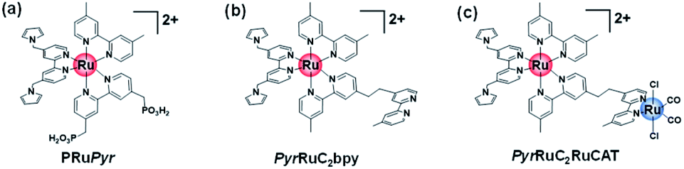 | ||
| Scheme 3 Molecular structures of (a) PRuPyr, (b) PyrRuC2bpy, and (c) PyrRuC2RuCAT. | ||
A three-step method was used to prepare NiO/PRu-PolyPyr-RuC2RuCAT1 as a dye-sensitized molecular photocathode (Scheme 4 and Fig. S3†). The NiO electrode was first modified with PRuPyr to give NiO/PRuPyr, in which the methylphosphonic acid groups of the diimine ligand work as anchors to the NiO electrode (process 1) (Scheme 4a). In the second step, NiO/PRuPyr was used as the working electrode for the oxidative electropolymerization of PyrRuC2bpy dissolved in MeCN containing Et4NBF4 (0.1 M) as an electrolyte (process 2) (Scheme 4b). Oxidative cyclic voltammetry cycling was carried out 25 times between E = 0 and +1.35 V vs. Ag/AgNO3 at 100 mV s−1, and the gradual increase of redox wave intensity after each scan (Fig. 3a) indicated the development of a polymer layer on the electrode to give NiO/PRu-PolyPyr-RuC2bpy. Finally, NiO/PRu-PolyPyr-RuC2bpy with free diimine moieties was reacted with [Ru(CO)2Cl2]n in MeCN solution at room temperature to give NiO/PRu-PolyPyr-RuC2RuCAT1 with Ru(diimine)(CO)2Cl2-type complexes in the polypyrrole layer as catalytic units (process 3) (Fig. S3†) (Scheme 4c).
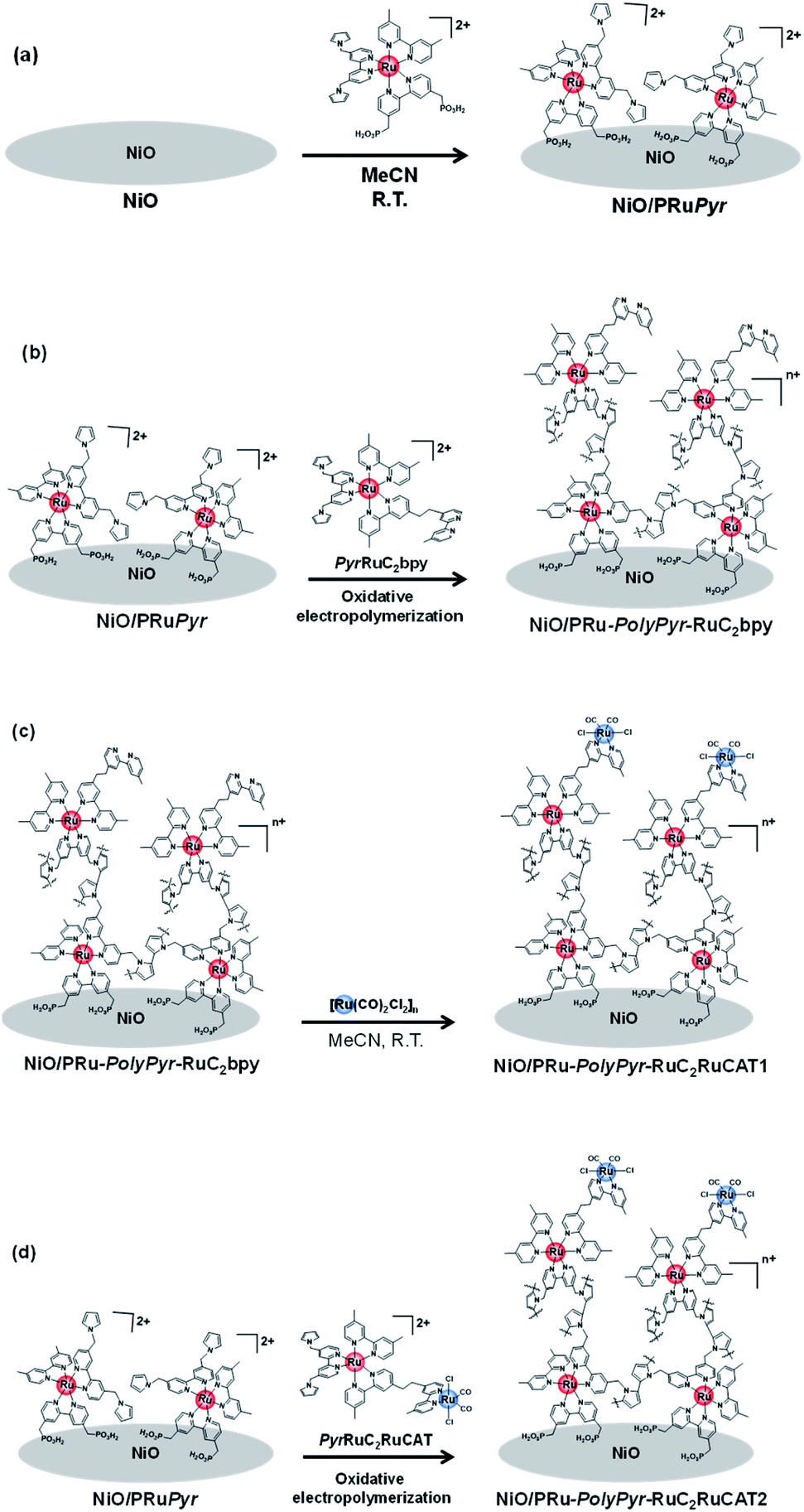 | ||
| Scheme 4 Preparation of (a) NiO/PRuPyr (step 1), (b) NiO/PRu-PolyPyr-RuC2bpy (step 2), and (c) NiO/PRu-PolyPyr-RuC2RuCAT1 (step 3) electrodes of a three step method of photocathode fabrication and (d) fabrication of NiO/PRu-PolyPyr-RuC2RuCAT2 electrode by a two-step method (step 2). | ||
 | ||
| Fig. 3 Cyclic voltammograms recorded during the electropolymerization of (a) PyrRuC2bpy and (c) PyrRuC2RuCAT on NiO/PRuPyr (area = 2.5 cm2) in Ar-saturated MeCN containing the corresponding complex (0.5 mM) and Et4NBF4 (0.1 M) as an electrolyte. The applied potential was repeatedly cycled (25 times) between 0 and +1.35 V vs. Ag/AgNO3 at 100 mV s−1. Cyclic voltammograms of (b) NiO/PRu-PolyPyr-RuC2RuCAT1 and (d) NiO/PRu-PolyPyr-RuC2RuCAT2 electrodes recorded in Ar-purged MeCN containing 0.1 M Et4NBF4 using a Ag/AgNO3 reference electrode and a Pt counter electrode (scan rate = 10 mV s−1). | ||
The synthesized electrodes were characterized by cyclic voltammetry (Fig. 3b and d), spectrophotometry, time-of-flight secondary ion mass spectrometry (TOF-SIMS), X-ray photoelectron spectroscopy (XPS), and SEM-based morphological analysis.
Fig. 4a shows the UV-vis DR spectra of NiO/PRu-PolyPyr-RuC2RuCAT1, revealing an increase in the intensity of the 1MLCT absorption band of Ru complexes after polymerization (process 2), while no such increase was observed after the formation of Ru catalyst units (process 3). This is reasonable, as Ru(diimine)(CO)2Cl2-type complexes have no strong absorption at wavelengths above 350 nm.12 The Fourier transform infrared (FT-IR) DR spectrum of NiO/PRu-PolyPyr-RuC2RuCAT1 showed two strong broad peaks at 2058 and 1986 cm−1, which were attributed to the C![[double bond, length as m-dash]](https://www.rsc.org/images/entities/char_e001.gif) O stretches of CO ligands in catalyst units, whereas no such peaks were observed for NiO/PRu-PolyPyr-RuC2bpy (Fig. 4b). The CO stretching frequencies well agreed with those of the corresponding binuclear Ru(II) complex ([cis-(CO)-trans-(Cl)-Ru(CO)2Cl2(bpyC2bpy)Ru(dmb)2](PF6)2 (bpyC2bpy = 1,2-bis(4′-methyl-[2,2′-bipyridine]-4-yl)ethane)) drop-cast on the NiO electrode (2058 and 1991 cm−1).12Fig. 4c and d show the X-ray photoelectron spectra of NiO/PRu-PolyPyr-RuC2RuCAT1 with the Ru catalyst unit and catalyst-free NiO/PRu-PolyPyr-RuC2bpy. Although both compounds featured a Ru 3d peak at 281.1 eV (Fig. 4c), only NiO/PRu-PolyPyr-RuC2RuCAT1 showed a Cl 2p peak at 198.4 eV (Fig. 4d). These results suggested that the Ru(II) catalyst units on and/or in the polypyrrole polymer on the electrode existed predominantly in the form of cis-(CO)-trans-(Cl)-Ru(diimine)(CO)2Cl2, which has been investigated as a catalyst for CO2 reduction in various photo- and electrocatalytic reactions.48–50
O stretches of CO ligands in catalyst units, whereas no such peaks were observed for NiO/PRu-PolyPyr-RuC2bpy (Fig. 4b). The CO stretching frequencies well agreed with those of the corresponding binuclear Ru(II) complex ([cis-(CO)-trans-(Cl)-Ru(CO)2Cl2(bpyC2bpy)Ru(dmb)2](PF6)2 (bpyC2bpy = 1,2-bis(4′-methyl-[2,2′-bipyridine]-4-yl)ethane)) drop-cast on the NiO electrode (2058 and 1991 cm−1).12Fig. 4c and d show the X-ray photoelectron spectra of NiO/PRu-PolyPyr-RuC2RuCAT1 with the Ru catalyst unit and catalyst-free NiO/PRu-PolyPyr-RuC2bpy. Although both compounds featured a Ru 3d peak at 281.1 eV (Fig. 4c), only NiO/PRu-PolyPyr-RuC2RuCAT1 showed a Cl 2p peak at 198.4 eV (Fig. 4d). These results suggested that the Ru(II) catalyst units on and/or in the polypyrrole polymer on the electrode existed predominantly in the form of cis-(CO)-trans-(Cl)-Ru(diimine)(CO)2Cl2, which has been investigated as a catalyst for CO2 reduction in various photo- and electrocatalytic reactions.48–50
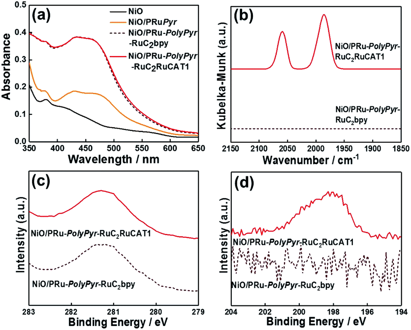 | ||
| Fig. 4 (a) UV-vis (DR) absorption spectra of NiO/PRu-PolyPyr-RuC2RuCAT1 prepared by the three-step method (red), NiO (black), and samples obtained after process 1 (NiO/PRuPyr, orange) and process 2 (NiO/PRu-PolyPyr-RuC2bpy, dotted brown). (b) FT-IR (DR) spectra of NiO/PRu-PolyPyr-RuC2RuCAT1 (red) and NiO/PRu-PolyPyr-RuC2bpy (dotted brown) recorded at a scan rate of 2 cm−1 s−1. (c) Ru 3d and (d) Cl 2p X-ray photoelectron spectra of NiO/PRu-PolyPyr-RuC2RuCAT1 (red) and NiO/PRu-PolyPyr-RuC2bpy (dotted brown). | ||
The SEM images of NiO/PRu-PolyPyr-RuC2RuCAT1 and the bare NiO electrode reveals that polypyrrole-containing Ru complex units formed not only on the surface of the NiO electrode but also inside the NiO layer (Fig. 2a and d). The Ru complexes could sufficiently penetrate into the depth of electrodes owing to the porosity of the NiO electrode.
Fig. 5 shows the results of TOF-SIMS analysis, indicating the distribution of elements in the depth direction from the electrode surface, with the sputter time on the x-axis corresponding to the cross-sectional component in the depth direction.
 | ||
| Fig. 5 TOF-SIMS spectra of (a) NiO/PRu-PolyPyr-RuC2RuCAT1, (b) NiO/PRu-PolyPyr-RuC2bpy, (c) NiO/PRuPyr, and (d) NiO electrodes. | ||
Although the density of Ru+ species on the electrode surface was highest for NiO/PRu-PolyPyr-RuC2RuCAT1, a relatively high intensity of these species was observed throughout the entire range of the NiO layer. This finding supports the conclusion that Ru complex units were fixed not only on the surface of the electrode, but also within its interior. Both the photosensitizer and catalyst moieties should be similarly dispersed on and in the NiO electrode because of the similarity of the TOF-SIMS spectra of NiO/PRu-PolyPyr-RuC2RuCAT1 and NiO/PRu-PolyPyr-RuC2bpy. A comparison of these spectra with that of NiO-PRuPyr indicates that polymerization increased the number of Ru complex units, especially in the NiO layer. The densities of BF4− and Et4N+ in NiO/PRu-PolyPyr-RuC2RuCAT1 were also measured using the TOF-SIMS analysis (Fig. S4†). BF4− was observed throughout the entire range of the NiO layer while no Et4N+ was detected. This indicates that remove of reductants ions were achieved by the post handling after the polymerization (Experimental section).
We determined the total amount of the adsorbed Ru complexes on each electrode by using the ICP-MS analysis. The results are summarized in Table 1. The amount of the photosensitizers clearly increased after the oxidative polymerization: the amount of Ru(II) photosensitizer of NiO/PRu-PolyPyr-RuC2bpy (step-2) was 30.2 nmol cm−2 while that of NiO/PRuPyr (after the step-1) was 6.2 nmol cm−2. After incorporation of the catalysts into the polymer electrode a total amount of Ru complexes increase again to 40.1 nmol cm−2. Therefore, the adsorbed amount of the Ru catalysts was 9.9 nmol cm−2 in the case of NiO/PRu-PolyPyr-RuC2RuCAT1, which is about one third of the photosensitizers. This means about 14 nmol cm−2 of the free bpy units remained in NiO/PRu-PolyPyr-RuC2RuCAT1. Limitation of space in the polypyrrole polymer might suppress the reaction of these bpy units with the precursor of the catalyst in the step 3.
| Sample | n Rutotal (nmol) | n RuPS (nmol) | n RuCAT (nmol) |
n
RuPS![[thin space (1/6-em)]](https://www.rsc.org/images/entities/char_2009.gif) :nRuCAT :nRuCAT |
|---|---|---|---|---|
| a Total amount in the electrode, which was estimated by using ICP-MS analysis. b Amount of the photosensitizers. c Amount of the catalysts. | ||||
| NiO/PRuPyr | 15.5 | 15.5 | 0 | — |
| NiO/PRu-PolyPyr-RuC2bpy | 75.4 | 75.4 | 0 | — |
| NiO/PRu-PolyPyr-RuC2RuCAT1 | 100.3 | 75.4 | 24.9c | 3:1 |
| NiO/PRu-PolyPyr-RuC2RuCAT2 | 40.7 | 28.1 | 12.1c | 2.3:1 |
The amounts of electrochemically active photosensitizers after each step were determined by cyclic voltammetric analysis of the film (Table 2).27 The electroactive photosensitizers were also increased after each adsorption steps of the photosensitizers: 2.0 nmol cm−2 (NiO/PRuPyr) and 9.6 nmol cm−2 (NiO/PRu-PolyPyr-RuC2bpy). After the introduction of the catalysts, the amounts of electrochemically active photosensitizers slightly increased (11.6 nmol cm−2, NiO/PRu-PolyPyr-RuC2RuCAT1) probably because of small morphology change of the polypyrrole phase during the reaction. The proportion of the electroactive photosensitizers to the total amount of the photosensitizers was about 0.3 (Table 2). Although this result indicates that major part of the immobilized photosensitizers was silent during the electrochemical scans, the non-electroactive photosensitizers possibly worked in the photocatalytic reactions owing to slower electron hoping than the time scale of the CV measurements and/or electron transfer in the excited state.
| Sample | Ru(ICP-MS)a (nmol cm−2) | Ru(CV)b (nmol cm−2) | Ru (CV) |
|---|---|---|---|
| Ru(ICP-MS) | |||
| a Total amounts of Ru complexes in each electrode, that were measured by using ICP-MS analysis. b Amounts of electroactive Ru complexes measure by using CV analysis. | |||
| NiO/PRuPyr | 6.2 | 2.0 | 0.32 |
| NiO/PRu-PolyPyr-RuC2bpy | 30.2 | 9.6 | 0.32 |
| NiO/PRu-PolyPyr-RuC2RuCAT1 | 40.1 | 11.6 | 0.29 |
| NiO/PRu-PolyPyr-RuC2RuCAT2 | 16.3 | 4.4 | 0.27 |
The stability of NiO/PRu-PolyPyr-RuC2RuCAT1 in an aqueous solution containing 50 mM NaHCO3 (this solution was used for photocatalytic CO2 reduction, as described below) was checked by spectrophotometric and electrochemical analyses using NiO/PRuPyr as a reference sample without polymerization. The voltammograms of NiO/PRu-PolyPyr-RuC2RuCAT1 recorded before and after 24 h soaking in the above solution (Fig. 6a) indicated that much less than 5% of the electroactive Ru(II) complexes was detached from the electrode, whereas, in the case of NiO/PRuPyr (Fig. 6b), more than 70% of PRuPyr adsorbed on the NiO electrode through methylphosphonic acid groups was detached into the aqueous solution. A much stronger immobilization of the Ru complex units in the polypyrrole layer on the electrode was also confirmed by spectrophotometric analysis. Specifically, the 1MLCT absorption band in the UV-vis (DR) spectrum of NiO/PRu-PolyPyr-RuC2RuCAT1 remained almost unchanged after soaking (Fig. 6c), and no Ru complexes were observed in the soaking solution (Fig. 6e). On the other hand, almost no 1MLCT absorption was observed in the UV-vis (DR) spectrum of soaked NiO/PRuPyr, and the absorption of dissolved PRuPyr was observed in the corresponding soaking solution (Fig. 6d and f). These results indicated that the fixation of Ru complexes using the polypyrrole layer is a very powerful means of preventing their detachment from the electrode in this solution.
 | ||
| Fig. 6 Stability of photocathodes against 24 h soaking in 50 mM aqueous NaHCO3 in the dark. Cyclic voltammograms of (a) NiO/PRu-PolyPyr-RuC2RuCAT1 and (b) NiO/PRuPyr before and after soaking. UV-vis (DR) absorption spectra of (c) NiO/PRu-PolyPyr-RuC2RuCAT1 and (d) NiO/PRuPyr before and after soaking. UV-vis absorption spectra of soaking solutions obtained for (e) NiO/PRu-PolyPyr-RuC2RuCAT1 and (f) NiO/PRuPyr. | ||
Another dye-sensitized molecular photocathode (NiO/PRu-PolyPyr-RuC2RuCAT2) was prepared by a simple two-step method. In this case, the NiO/PRuPyr electrode was used as the working electrode for the oxidative electropolymerization of PyrRuC2RuCAT, which already has both photosensitizer and catalyst units, in MeCN containing Et4NBF4 (0.1 M) as an electrolyte. Oxidative cyclic voltammetry cycling was performed between 0 and +1.35 V vs. Ag/AgNO3 at 100 mV s−1 (Scheme 4a and d), i.e., under the same polymerization conditions as those used for NiO/PRu-PolyPyr-RuC2RuCAT1. The voltammograms recorded during electrochemical polymerization (Fig. 3c) resembled those obtained after process 2 using PyrRuC2bpy (Fig. 3a). This is reasonable, as the oxidation potential of the incorporated catalyst unit is more positive than that of the pyrrole groups (Fig. S5†). In other words, the catalyst unit incorporation did not affect the oxidative polymerization of pyrrole groups. We can use the amounts of the Ru complexes in NiO/PRuPyr and NiO/PRu-PolyPyr-RuC2RuCAT2, which were obtained by using the ICP-MS analysis, to determine both amounts of the photosensitizers and catalysts in NiO/PRu-PolyPyr-RuC2RuCAT2 because we can assume that the adsorbed amounts of the photosensitizer and catalyst units to NiO/PRuPyr (step 2 in the two-step method) was same to each other because the Ru(II)–Ru(II) supramolecule with the 1:1 ratio between the photosensitizer and catalyst units was used as the monomer for the polymerization. These results are summarized in Table 1. Both amounts of the adsorbed photosensitizers and the catalysts in NiO/PRu-PolyPyr-RuC2RuCAT2 were less than half of those in NiO/PRu-PolyPyr-RuC2RuCAT1. This difference was ascribed to the much higher bulkiness of the RuCAT unit of PyrRuC2RuCAT compared to that of the free diimine unit of PyrRuC2bpy, which possibly suppressed the supply of PyrRuC2RuCAT to NiO particles at the electrode depth. The number of active Ru complexes in NiO/PRu-PolyPyr-RuC2RuCAT2 estimated by cyclic voltammetry of the polymer electrode (4.4 nmol cm−2, Fig. 3d) was smaller than that of the electrode prepared using the abovementioned three-step method (11.6 nmol cm−2, Fig. 3b).
In the case of NiO/PRu-PolyPyr-RuC2RuCAT2, similar structures and stabilities of Ru complex units in the polypyrrole layer were confirmed by UV-vis DR spectroscopy (Fig. 7a), FT-IR spectroscopy (Fig. 7b), TOF-SIMS (Fig. 7c), and SEM (Fig. 2b). Notably, the catalytic unit with the cis-(CO)-trans-(Cl)-Ru(diimine)(CO)2Cl2 structure did not change during oxidative polymerization. This is one of critical differences of the oxidative polymerization method of the pyrrole groups from the previously reported reductive polymerization method using a similar Ru(II)–Ru(II) supramolecular photocatalyst with vinyl groups instead of the pyrrole groups, noticeable shifts in CO stretching frequencies were observed after the reductive polymerization.12 This finding suggested the formation of Ru–C bonds during the reductive polymerization, which induced the desorption of complexes from the electrode during photocatalytic reactions.12 Such decomposition process of the photoanode was not observed in the system using NiO/PRu-PolyPyr-RuC2RuCAT2.
 | ||
| Fig. 7 (a) UV-Vis (DR) absorption spectra of NiO/PRu-PolyPyr-RuC2RuCAT2 (red), NiO/PRuPyr (orange), and NiO (black). (b) FT-IR (DR) spectra of NiO/PRu-PolyPyr-RuC2RuCAT2 (red) and PyrRuC2RuCAT cast on NiO (blue). (c) TOF-SIMS spectra of NiO/PRu-PolyPyr-RuC2RuCAT2. | ||
Photoresponses of dye-sensitized molecular photocathodes
Fig. 8a presents the I–V curve (linear sweep voltammogram) of NiO/PRu-PolyPyr-RuC2RuCAT1 recorded during irradiation at λex = 460–650 nm in CO2-purged aqueous 50 mM NaHCO3 as the electrolyte, revealing a photocathodic current response starting from E = +0.4 V vs. Ag/AgCl. The photocurrent steadily increased up to E = −0.2 V, saturating at more negative potentials. This photocurrent increase was faster than that of a previously reported NiO/PRu-PolyVinyl-RuC2RuCAT photocathode12 prepared by a similar three-step method except for the reductive polymerization of the vinyl groups of the Ru photosensitizer units instead of the oxidative polymerization of the pyrrole groups. Specifically, the maximum photocurrent (61 μA cm−2) was achieved even at E = −0.2 V in the case of NiO/PRu-PolyPyr-RuC2RuCAT1, whereas E = −0.5 V was required to maximize the photocurrent of NiO/PRu-PolyVinyl-RuC2RuCAT (28.0 μA cm−2 at E = −0.2 V, 38.0 μA cm−2 at E = −0.5 V). At E = 0 V, NiO/PRu-PolyPyr-RuC2RuCAT1 maintained ∼83% of the maximum photocurrent density, whereas this number equalled only 45% for NiO/PRu-PolyVinyl-RuC2RuCAT. These results strongly indicated that the electric resistance of the polypyrrole layer in NiO/PRu-PolyPyr-RuC2RuCAT1 was lower than that of the polyvinyl layer in NiO/PRu-PolyVinyl-RuC2RuCAT.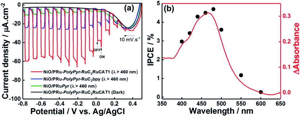 | ||
| Fig. 8 (a) Responses of NiO/PRuPyr (green), NiO/PRu-PolyPyr-RuC2bpy (blue), and NiO/PRu-PolyPyr-RuC2RuCAT1 (red) to irradiation at λex = 460–650 nm (intensity = 28.2 mW cm−2) in CO2-purged 50 mM aqueous NaHCO3 (pH 6.6, Ag/AgCl reference electrode, Pt wire counter electrode). (b) Effect of wavelength on the IPCE of NiO/PRu-PolyPyr-RuC2RuCAT1 at −0.3 V vs. Ag/AgCl in a CO2-purged 50 mM NaHCO3 aqueous solution (pH 6.6, black dots). The red line shows the UV-vis absorption spectrum of NiO/PRu-PolyPyr-RuC2RuCAT1 with subtracted absorbance of the NiO electrode. | ||
The dependence of IPCE on the wavelength of irradiated light (Fig. 8b) well agreed with the behaviour of the 1MLCT absorption band of Ru complex photosensitizer moieties. Therefore, the cathodic photocurrent was exclusively generated by the excitation of Ru photosensitizer moieties in the polymerized layer on the NiO electrode. The maximum IPCE (4.7% at λex = 480 nm) was approximately four times higher than that of a previously reported system with NiO/PRu-PolyVinyl-RuC2RuCAT (IPCE = 1.2%).12
The responses of photocathodes obtained after each fabrication step were observed at E = −0.7 V and equaled 9.8 μA cm−2 for NiO/PRuPyr prepared by process 1 and 24.5 μA cm−2 for NiO/PRu-PolyPyr-RuC2bpy prepared by process 2. Both of these values were much lower than that observed for NiO/PRu-PolyPyr-RuC2RuCAT1 (57 μA cm−2).
Photoelectrochemical CO2 reduction over dye-sensitized molecular photocathodes
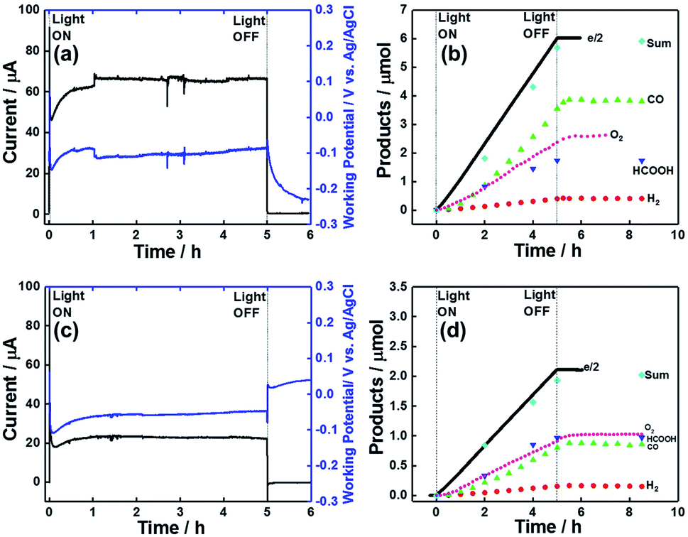
The photocatalytic activity of dye-sensitized molecular photocathodes for CO2 reduction under external bias was evaluated using them as working electrodes and Pt wire as a counter electrode. These electrodes were set in each compartment of an H-shaped cell, in which the compartments were separated using a Nafion® membrane, and a Ag/AgCl (Sat. KCl aq.) KCl reference electrode was set in the same compartment as the dye-sensitized molecular photocathode. Aqueous 50 mM NaHCO3 as the electrolyte was introduced into the cell and purged with CO2 for 30 min. The compartment with the dye-sensitized photocathode was irradiated at λex = 460–650 nm using a 300 W Xe lamp with a cutoff filter under applied biases of Eapp = 0, −0.3, and −0.7 V. During irradiation, CO2 flowed into the solution, and the flow gas was analysed by a micro-GC to determine the levels of the produced CO and H2. The reaction solution was sampled using a syringe through a septum cap attached to the cathodic compartment. Fig. 9a shows the irradiation time–dependent photocurrent at Eapp = −0.7 V in the system with NiO/PRu-PolyPyr-RuC2RuCAT1 as the photocathode, revealing that a continuous photocathodic current of 57 to 43 μA was observed over 24 h. CO and HCOOH were continuously formed as major products along with small amounts of H2 (Fig. 9b). The CO2 reduction selectivity equalled 92%, while the faradaic efficiency (Fred) of this reduction equalled 96% after 24 h irradiation, even though the photocatalytic reaction proceeded in an aqueous solution with pH 6.8. The product turnover numbers after 24 h irradiation equalled 566.3 (CO), 184.7 (HCOOH), and 72.3 (H2) (entry 2 in Table 3), and the number of Ru catalyst moieties was estimated by ICP-MS analysis as 24.9 nmol (see experimental). | ||
| Fig. 9 Time courses of (a and c) photocurrent and (b and d) product levels expressed as half of electrons passed (black line), CO (green triangles), HCOOH (blue triangles), and H2 (red circles). (a and b) NiO/PRu-PolyPyr-RuC2RuCAT1, (c and d) NiO/PRu-PolyPyr-RuC2RuCAT2 (electrode area = 2.5 cm2, applied bias (E) = −0.7 V vs. Ag/AgCl) were irradiated at λex = 460–650 nm (32 mW cm−2) in CO2-purged 50 mM aqueous NaHCO3 (pH 6.6). | ||
| Entry | Electrode | Irradn time (h) | E app (V) | Light intensity (mW cm−2) | Products/μmol (TON) | F red (%) | CO2 red selectivity (%) | ||
|---|---|---|---|---|---|---|---|---|---|
| CO | HCOOH | H2 | |||||||
| a Applied potential vs. Ag/AgCl. b Faradaic efficiency of the total production of CO, HCOOH. c Without process 1. d Not detected. e Reference 12. | |||||||||
| 1 | NiO/PRu-PolyPyr-RuC2RuCAT1 | 5 | −0.7 | 32 | 3.8 (152.6) | 1.0 (40.2) | 0.4 (16.1) | 91 | 93 |
| 2 | 24 | −0.7 | 32 | 14.1 (566.3) | 4.6 (184.7) | 1.8 (72.3) | 96 | 92 | |
| 3 | 24 | −0.3 | 27 | 5.2 (208.8) | 2.9 (116.5) | 1.0 (40.2) | 91 | 89 | |
| 4 | 24 | 0.0 | 28 | 2.2 (88.4) | 2.1 (84.3) | 0.9 (36.1) | 71 | 82 | |
| 5 | 24 | −0.7 | 8 | 4.9 (196.8) | 3.2 (128.5) | 1.1 (44.2) | 87 | 89 | |
| 6 | NiO/PRu-PolyPyr-RuC2RuCAT2 | 24 | −0.7 | 36 | 7.8 (619) | 3.4 (269.8) | 1.4 (111.1) | 93 | 89 |
| 7 | NiO/PRu-PolyPyr-RuC2RuC2bpy | 5 | −0.7 | 36 | 0.1 | 0.1 | 1.1 | 92 | 19 |
| 8 | NiO/PolyPyr-RuC2RuCATc | 5 | −0.7 | 32 | 0.2 | 0.6 | <0.1 | 83 | 91 |
| 9 | NiO/PRuPyr | 5 | −0.7 | 32 | n.d.d | n.d.d | <0.1 | 9 | n.d.d |
| 10e | NiO/PRuC2RuCAT | 5 | −0.7 | 27 | <0.1 | 0.2 | <0.1 | 56 | 82 |
Control experiments performed without irradiation, without applied potential, or under an Ar atmosphere using phosphate buffer (pH 7.4) instead of NaHCO3 as an electrolyte gave no or less CO2 reduction products (Table S5†), suggesting that light, applied bias, and CO2 are required for photocatalytic CO2 reduction. Compared to NiO/PRu-PolyPyr-RuC2RuCAT1, the catalyst unit–free NiO/PRu-PolyPyr-RuC2bpy showed no significant activity for CO2 reduction but afforded some H2 upon irradiation (entry 7 in Table 3), which indicated that the Ru catalyst unit is essential for the photocatalytic reduction of CO2 in this photoelectrochemical system.
Fig. 10a shows a GC-MS chromatogram of the gas phase formed in the photocathode compartment after 24 h irradiation of the system containing 13CO2 and NaH13CO3, indicating the almost selective formation of 13CO (m/z = 29). On the other hand, a similar experiment with ordinary CO2 and NaHCO3 afforded a main peak at m/z = 28 (12CO; Fig. 10b). Fig. 11 shows the 1H NMR spectra of the reaction solution formed in the cathodic compartment after irradiation. In the case of 13CO2 and NaH13CO3, a doublet attributable to H13COO− was observed at 8.26 ppm (JCH = 196 Hz) because of 1H–13C coupling, while a singlet was observed at 8.26 ppm for the system with ordinary CO2 and NaHCO3. These isotope labelling experiments confirmed that CO2 acted as a source of carbon in the photocatalytic reduction products (CO and HCOOH).
 | ||
| Fig. 10 GC-MS chromatograms of the gas phase formed in cells after irradiation, showing the peaks at m/z = 28 and 29 (12CO and 13CO, respectively). NiO/PRu-PolyPyr-RuC2RuCAT1 was subjected to an applied bias of E = −0.7 V vs. Ag/AgCl and irradiated at λex = 460–650 nm in CO2-purged 50 mM aqueous NaHCO3 (pH = 6.6) for 24 h using (a) 13CO2 and NaH13CO3 and (b) ordinary CO2 and NaHCO3. | ||
 | ||
| Fig. 11 1H NMR spectra of the solution obtained after photoelectrochemical reduction. NiO/PRu-PolyPyr-RuC2RuCAT1 was subjected to a potential of E = −0.7 V vs. Ag/AgCl and irradiated at λex = 460–650 nm in CO2-purged 50 mM aqueous NaHCO3 (pH = 6.6) for 24 h using 13CO2 and NaH13CO3 (blue) or ordinary CO2 and NaHCO3 (red). | ||
After the photocatalytic reaction, the photocathode was analysed by UV-vis DR spectroscopy, FT-IR (DR) spectroscopy, and XPS. Almost no changes were observed in the UV-vis DR spectra after the reaction (Fig. 12a), and no desorbed Ru(II) trisdiimine complexes were observed in the reaction solution (Fig. 12b). These results indicate that the Ru(II) photosensitizer units were stable and that the polypyrrole layer was strong enough to keep the Ru photosensitizer units in its layer during the photocatalytic reaction for at least one day. Fig. 12c shows the expanded FT-IR (DR) spectra depicting the νCO bands before and after the reaction. Although these bands were still observed after the reaction, they were shifted to lower wavenumbers (νCO = 1945, 2030 cm−1), which suggest that the Cl− ligands of Ru catalyst units were replaced with electron-donating ligands such as OH− or HCOO−. The exchange of Cl− ligands during the photocatalytic reaction was further confirmed by the disappearance of the Cl 2p peaks in the X-ray photoelectron spectra (Fig. 12d), which indicate that the loss of Cl− mostly proceeded within the initial 15 min of the photocatalytic reaction. As the concentration change of Ru catalyst units could not be determined, one cannot discuss the reason(s) of why the photocatalytic reaction rate decreased with time, even though it remained at 76% of the initial value after 24 h (Fig. 9a).
 | ||
| Fig. 12 (a) UV-Vis DR spectra of NiO/PRu-PolyPyr-RuC2RuCAT1 before (red) and after (blue) photoelectrochemical CO2 reduction (−0.7 V vs. Ag/AgCl, λex = 460–650 nm, 24 h) in CO2-purged 50 mM aqueous NaHCO3. (b) UV-vis absorption spectrum of the reaction solution after the photocatalytic reaction. (c) FT-IR (DR) spectra of NiO/PRu-PolyPyr-RuC2RuCAT1 before (red) and after (blue) the photocatalytic reaction. (d) Cl 2p spectra of NiO/PRu-PolyPyr-RuC2RuCAT1 before and after the photocatalytic reaction for various times. | ||
The formation of reduction products became slower at lower applied potentials, i.e., at Eapp = −0.3 and 0 V (entries 3 and 4 in Table 3), even though the photocurrents at Eapp ≤ −0.2 V were similar (Fig. 8). The back electron transfer from the reduced Ru complex units to the electrode might have proceeded more efficiently at Eapp = −0.3 V than at Eapp = −0.7 V. It should be noted, however, that photocatalytic CO2 reduction still actively proceeded even at Eapp = 0 V. Interestingly, the HCOOH:CO ratio at these lower applied potentials exceeded that obtained at Eapp = −0.7 V (entry 2 in Table 3). A similar change in reduction product ratio, that is, a decrease in the fraction of CO, was observed with decreasing irradiation intensity (32 → 8 mW cm−2) even at Eapp = −0.7 V (entries 2 and 5 in Table 3 and Fig. S6†). These results suggest that slower electron injection into the catalyst units favours the formation of HCOOH. Ishida et al. reported a similar phenomenon in homogeneous solutions, i.e., the HCOOH:CO ratio increased with decreasing irradiation intensity in the homogeneous photocatalytic reduction of CO2 promoted by a mixture of Ru(bpy)(CO)2Cl2 and [Ru(bpy)3]2+ (bpy = 2,2′-bipyridine), and proposed that slower injection into the one-electron-reduced intermediate produced from the Ru catalyst induces the formation of a Ru catalyst dimer, with further reduction affording HCOOH.51 Kubiak et al. proposed that in the electrocatalytic reduction of CO2 using Ru(6Mesbpy)(CO)2Cl2, the bpy ligand of which has bulky mesityl groups at 6,6′-positions to suppress dimerization, slower electron injection into a Ru(II) formate complex as an intermediate of both CO and HCOOH formation induces the loss of the formate ligand from the Ru catalyst unit.52 Although we cannot clarify the real reason of why faster electron injection into the Ru catalyst unit favours CO production, we note that the selectivity for CO2 over H2 remained high even in slower-electron-injection systems.
Subsequently, we determined the optimal number of potential sweeps in the polymerization of PyrRuC2bpy with NiO/PRuPyr (process 2) for the photocatalytic reduction of CO2 (Fig. S7,†Table 4). The best performance was obtained for the photoelectrode prepared by 25 sweeps (entry 4, Table 4), in good agreement with the electrochemical properties of the photoelectrodes described in the section “Optimization of redox photosensitizer layer on electrodes.” Notably, the photoelectrode prepared by continuous electrolysis at a fixed potential (1.3 V vs. Ag/AgNO3) for 30 min exhibited poor photocatalytic performance (entry 6, Table 4).
| Entry | Number of sweeps | e −/2 μmol | Product/μmol | F red (%) | CO2 red. selectivity (%) | ||
|---|---|---|---|---|---|---|---|
| CO | HCOOH | H2 | |||||
| a Electrolysis for the polymerization was performed at 1.3 V vs. Ag/AgNO3 for 30 min. b Without using PRuPyr to make the photocathode. | |||||||
| 1 | 5 | 0.99 | 0.2 | 0.4 | 0.1 | 77 | 70 |
| 2 | 10 | 1.69 | 0.6 | 0.6 | 0.1 | 83 | 90 |
| 3 | 20 | 4.12 | 2.5 | 1.0 | 0.3 | 91 | 93 |
| 4 | 25 | 4.89 | 2.9 | 1.0 | 0.3 | 91 | 92 |
| 5 | 50 | 2.99 | 2.0 | 0.7 | 0.2 | 97 | 94 |
| 6 | Fixeda | 1.35 | 0.6 | 0.6 | 0.1 | 94 | 91 |
| 7 | 25b | 0.95 | 0.2 | 0.6 | <0.1 | 83 | 91 |
To check the necessity of the first process of NiO/PRu-PolyPyr-RuC2RuCAT1 fabrication (process 1), we performed the direct polymerization of PyrRuC2bpy on the NiO electrode without PRuPyr using 25 potential sweeps between 0 and +1.35 V vs. Ag/AgNO3 at 100 mV s−1, and the electrode was then reacted with [Ru(CO)2Cl2]n in MeCN solution at room temperature, as in processes 2 and 3 for the synthesis of NiO/PRu-PolyPyr-RuC2RuCAT1 (entry 7 in Table 4).
Although this photocathode without phosphonic acid anchoring groups showed a certain photoresponse, its photocatalytic activity was much poorer than that of NiO/PRu-PolyPyr-RuC2RuCAT1 (entry 7 in Table 4). Therefore, process 1 was concluded to be important for the synthesis of an efficient dye-sensitized molecular photocathode.
Fig. 9c and d show the photocatalytic performance of the system with NiO/PRu-PolyPyr-RuC2RuCAT2 as a photocathode under an applied bias of −0.7, revealing the continuous production of CO and HCOOH as the main products for 24 h. The faradaic efficiency of reduction was 93% after 24 h. As the number of Ru catalyst units in this photoelectrode (12.6 nmol) was much smaller than that in NiO/PRu-PolyPyr-RuC2RuCAT1 (24.9 nmol), the amount of reduction products was also smaller in the former system. However, the TONs obtained for NiO/PRu-PolyPyr-RuC2RuCAT2 (entry 6 in Table 3) exceeded those obtained for NiO/PRu-PolyPyr-RuC2RuCAT1 (entry 2 in Table 3).
In conclusion of this section, both NiO/PRu-PolyPyr-RuC2RuCAT1 and NiO/PRu-PolyPyr-RuC2RuCAT2 were found to be good dye-sensitized molecular photocathodes for photocatalytic CO2 reduction, exhibiting high selectivity, durability, and faradaic efficiency and featuring IPCEs much higher (IPCEmax = 4.7%) and onset potentials more positive than those of previously reported dye-sensitized molecular photocathodes (IPCEmax < 2%)11,12,19,27 such as NiO/PRu-PolyVinyl-RuC2RuCAT with a polyvinyl polymer layer instead of the polypyrrole layer.12 The faster electron hopping through the conjugated polypyrrole assembly should generate a higher photocurrent density at a lower bias in comparison with the polyvinyl-based electrodes. Therefore, polypyrrole systems are highly promising for the fabrication of good full-cell devices that drive photocatalytic CO2 reduction using water as the reductant under zero bias conditions with visible light irradiation as the only energy input. Owing to the faster speed of product formation, we chose NiO/PRu-PolyPyr-RuC2RuCAT1 as a photocathode for constructing full cells as follows.
Full cells for photocatalytic CO2 reduction coupled with water oxidation
We chose two types of photoanodes, i.e., BiVO4 modified with CoOx as a co-catalyst (CoOx/BiVO4)53,54 and TaON modified with RhOx as a co-catalyst (RhOx/TaON),55 as they were reported as stable semiconductor photoanodes for water oxidation under visible light irradiation with sufficient stability and sufficiently negative conduction band potentials to pass electrons to the valence band of NiO.56,57 The photoelectrochemical properties of CoOx/BiVO4 and RhOx/TaON were first checked by measuring their light responses (λex = 400–650 nm, 41.2 mW cm−2) (Fig. 13a, blue and gray lines), and in both cases, we observed good overlaps with the I–V curve of the NiO/PRu-PolyPyr-RuC2RuCAT1 photocathode (red line) in CO2-purged aqueous solutions containing 50 mM NaHCO3 as the electrolyte (pH = 6.6). Therefore, the above electrodes were then used for photocatalytic CO2 reduction. Relatively stable photocurrents continuously flowed in both photoanodes under low applied biases (Eapp = 0 or 0.1 V vs. Ag/AgCl) and visible light irradiation in the same solutions (Fig. 13b and S8†). We used two types of photoelectrochemical cells with the NiO/PRu-PolyPyr-RuC2RuCAT1 photocathode and the CoOx/BiVO4 or RhOx/TaON photoanode. One type of cells featured a two-compartment system where the photocathode and the photoanode were separated from each other by a Nafion® membrane and were irradiated using different light sources (32–34 mW cm−2 at λex = 460–650 nm for the photocathode, 28–32 mW cm−2 at λex = 400–650 nm for the photoanode (Scheme 5a). In cells of the other (tandem) type, both photoelectrodes were set in the same compartment. Simulated solar light (AM1.5) first illuminated the photocathode, and then the permeated light illuminated the photoanode (Scheme 5b, Fig. S9 and S10†). No external bias was applied to the photoelectrodes in either cell type, that is, visible light was the only energy source. | ||
| Fig. 13 (a) I–V curves of CoOx/BiVO4, RhOx/TaON, and NiO/PRu-PolyPyr-RuC2RuCAT1 as working electrodes recorded in CO2-purged aqueous NaHCO3 (50 mM) upon irradiation. Scan rate = 10 mV s−1, λex = 400–650 nm (41 mW cm−2) for CoOx/BiVO4 and RhOx/TaON, and λex = 460–650 nm (28mW cm−2) for NiO/PRu-PolyPyr-RuC2RuCAT1. (b) Time-dependent photocurrents of CoOx/BiVO4 at Eapp = 0 V (blue) and RhOx/TaON at E = 0 V (light grey) and 0.1 V (dark grey) vs. Ag/AgCl. | ||
 | ||
| Scheme 5 Schematics of a full cell comprising a CoOx/BiVO4 or RhOx/TaON photoanode and a NiO/PRu-PolyPyr-RuC2RuCAT1 photocathode. (a) Irradiation of a full cell with two compartments separated by a Nafion® membrane. (b) Tandem-type full cell with a single compartment. | ||
Fig. 14a shows the time courses of the electrode photocurrent and working potential in the two-component system with the CoOx/BiVO4 photoanode, revealing that they were stable during 5 h irradiation. During this irradiation, CO and HCOOH were constantly produced in the photocathodic compartment, while O2 was produced in the photoanodic compartment (Fig. 14b). The following results were obtained after 5 h: CO (3.90 μmol, TONCO = 156.6), HCOOH (1.82 μmol, TONHCOOH = 73.1), and O2 (2.60 μmol). The much lower amount of produced H2 (0.42 μmol) indicated high selectivity for CO2 reduction (93%). The faradaic efficiencies of the photocathode and photoanode equaled 99 and 87%, respectively. The highest energy conversion efficiency obtained in the reported full cells with dye-sensitized molecular photocathodes equaled 8.3 × 10⁻²% (Table 5). The full cell with the RhOx/TaON photoanode also drove the photocatalytic reduction of CO2 with water (Fig. 14c and d). The main product were also CO (0.88 μmol, TONCO = 35.3) and HCOOH (0.97 μmol, TONHCOOH = 39.0), and a high selectivity was observed for CO2 reduction (92%) in the photocathodic compartment, while O2 (1.02 μmol) was formed in the photoanodic compartment. Although a smaller photocurrent density was observed in this system, the faradaic efficiency of O2 evolution significantly improved to Fanode = 98% with Fcathode = 96%. The energy conversion efficiency equaled 2.0 × 10⁻²% (Table 5). The selectivity of O2 evolution in the system with the RhOx/TaON photoanode was higher than that in the system with the CoOx/BiVO4 photoanode, which produced O2 as well as H2O2, in line with previous reports.58–60
 | ||
| Fig. 14 (a and c) Time courses of electrode photocurrent (black) and working potential (blue), and (b and d) product amounts formed during visible light irradiation. Data recorded for photoelectrochemical cells with the NiO/PRu-PolyPyr-RuC2RuCAT1 photocathode and (a and b) the CoOx/BiVO4 photoanode (photocathode: λex = 460–650 nm, 32 mW cm−2, photoanode: λex = 400–650 nm, 28 mW cm−2) or (c and d) the RhOx/TaON photoanode (photocathode: λex = 460–650 nm, 34.4 mW cm−2, photoanode: λex = 400–650 nm, 32.2 mW cm−2) without any bias in aqueous CO2-purged NaHCO3 (50 mM, pH 6.6). | ||
| Photo-anode | Light intensity (mW cm−2) | Irradn time (h) | Products/μmol | F cathode (%) | F anode (%) | CO2 red. selectivity (%) | ECE (10−2%) | ||||
|---|---|---|---|---|---|---|---|---|---|---|---|
| e −/2 | CO | HCOOH | H2 | O2 | |||||||
| a At λex = 460–650 nm for photocathode. b At λex = 400–650 nm for photoanode. c AM1.5. | |||||||||||
| Two-component systems | |||||||||||
| CoOx/BiVO4 | 32.0a, 28.0b | 5 | 6.0 | 3.9 | 1.7 | 0.4 | 2.6 | 99 | 87 | 93 | 8.3 |
| RhOx/TaON | 34.4a, 32.2b | 5 | 2.1 | 0.9 | 1.0 | 0.2 | 1.0 | 96 | 97 | 92 | 2.0 |
|
|||||||||||
| One-component systems | |||||||||||
| CoOx/BiVO4 | 100c | 1 | 1.6 | 0.6 | 0.9 | 0.1 | 0.6 | 98 | 74 | 92 | 4.8 |
| RhOx/TaON | 100c | 1 | 1.0 | 0.4 | 0.5 | <0.1 | 0.5 | 95 | 96 | 95 | 2.7 |
The mechanism of the photocatalytic reduction of CO2 with water as the reductant in the full-cell system is illustrated in Scheme 5. Visible light is sequentially absorbed by the Ru(II) photosensitizer unit in the photocathode and n-type semiconductor (BiVO4 or TaON) in the photocathode, in which a two-photon process, the so-called Z-scheme, induces electron transfer from the photoanode to the photocathode, and causes both strong reduction and oxidation powers on each side. The produced active electron is finally transferred to the Ru(II) catalyst unit, and the hole is transferred to the co-catalyst (CoOx or RhOx).
These Z-scheme electron transfer processes continuously proceed during irradiation, inducing the two-electron reduction of one CO2 molecule on the photocathode and the four-electron oxidation of two water molecules to furnish CO, HCOOH, and O2 (partial two-electron oxidation of one water molecule to afford H2O2 also occurs on the CoOx/BiVO4 photoanode).
Conclusions
The introduction of a polypyrrole assembly into a dye-sensitized molecular photocathode as a connector between the redox photosensitizer, catalyst, and NiO electrode increased the photocatalytic performance of this electrode for CO2 reduction, especially IPCE, which was more than three times higher than that of a previously reported dye-sensitized molecular photocathode constructed by the polymerization of vinyl groups instead of pyrrole groups. The maximum photocurrent was obtained even at a low applied potential (E = −0.2 V vs. Ag/AgCl). The durability of the modified photoelectrode was reasonably good, i.e., 81% of the initial photocurrent was maintained even after 24 h irradiation. Full cells comprising this novel dye-sensitized molecular photocathode and the CoOx/BiVO4 or RhOx/TaON photocathode could efficiently and selectively reduce CO2 with water using visible light as the only energy source without any external bias, and the highest energy conversion efficiency was achieved in the reported full-cell systems with dye-sensitized molecular photocathodes.Experimental
General procedures
1H NMR (400 MHz) and 31P NMR (162 MHz) spectra were recorded on a JEOL ECA400-II spectrometer. Transmission FT-IR spectra of metal complexes in MeCN were recorded using a JASCO FT/IR-6600 spectrometer at a resolution of 1 cm−1. FT-IR spectra in DR mode were recorded using an FT/IR-6600 spectrometer equipped with a DR unit (DR-81, JASCO) at a resolution of 2 cm−1. Electrospray ionization-mass spectroscopy (ESI-MS) analyses were performed using a Shimadzu LC-MS-2010 system with MeCN as the mobile phase. Inductively coupled plasma mass spectrometry (ICP-MS) analyses were performed in H2O:HCl:H2SO4 (1:1:1) mixed acid solutions containing Ru complexes desorbed from the electrode. SEM images were obtained using a Hitachi S4700 system. The electrochemical analysis of metal complexes in MeCN solution and oxidative polymerization were performed in a three-electrode system using a BAS760Es electrochemical analyser. TOF-SIMS analyses were performed using a 5-100-AD instrument (ION-TOF GmbH). UV-vis absorption spectra in DR mode were recorded using a JASCO V-565 spectrophotometer. X-ray photoelectron spectra were recorded using a Shimadzu ESCA-4000 instrument, and Ru 3d and Cl 2p binding energies were corrected using the C 1s peak at 285.0 eV as a reference. The light responses of I–V curves during photoelectrochemical CO2 reduction were measured using a Hokuto Denko potentiostat (Hokuto Denko HZ-7000) with a MAX 303 light source equipped with HOYA Y48 (λ > 460 nm) or L42 (λ > 400 nm) cutoff filters. Gas analysis was carried out using a micro-GC instrument (Agilent), and isotopic labelling studies were performed using GC-MS (Shimadzu MS-2010).
Materials
Acetonitrile (MeCN) was distilled twice after refluxing over P2O5 overnight and then distilled over CaH2 immediately before use. Tetrabutylammonium tetrafluoroborate (Et4NBF4) was recrystallized from MeCN/ethyl acetate and then dried under reduced pressure at 373 K overnight before utilization. 13CO2 (99% 13C) was purchased from Cambridge Isotope Laboratories, Inc. NaH13CO3 (98% 13C) was purchased from Sigma Aldrich. 4,4′-Bis(bromomethyl)-2,2′-bipyridine,61 1,2-bis(4′-methyl-[2,2′-bipyridin]-4-yl)ethane (bpyC2bpy),62 4,4′-bis-(methylphosphonate)-2,2′-bipyridine ((Et2O3PCH2)2bpy),61 [Ru(dmb)2]Cl2,63,64 and [Ru(CO)2Cl2]n65 as well as NiO10 and CoOx/BiVO4 (ref. 12) photoanodes were prepared as reported elsewhere. Pyrrole (TCI, >99%) was freshly distilled under reduced pressure and immediately used for synthesis. All other reagents and solvents were commercially available and used without further purification. The synthetic scheme and 1H NMR spectra of all other metal complexes are given in the ESI† (SI-1).Synthesis
:2) mixture containing 0.1 M NH4PF6, and the product was isolated from the organic layer. The crude solids were recrystallized from acetone–diethyl ether to yield the final product as red crystals (50 mg, 72%). 1H NMR (400 MHz, acetone-d6) δ/ppm: 8.39 (s, 4H), 7.98 (s, 2H), 7.66 (d, J = 5.8 Hz, 2H), 7.55 (dd, 5.8, 2 Hz, 4H); 7.29 (m, 4H); 7.01 (m, 2H), 6.85 (t, J = 2.4 Hz, 4H), 6.28 (t, J = 2.4 Hz, 4H), 5.36 (s, 4H), 2.57 (d, J = 6 Hz, 12H). ESI-MS (in MeCN): m/z = 392.0 [M–2PF6−]2+. Elemental analysis: C (49.22%), H (3.81%), and N (10.25%), calculated for C44H42N8P2F12Ru: C (49.15%), H (3.94%), and N (10.42%).
:2) mixture containing 0.1 M NH4PF6. The product was isolated from the organic layer, and the obtained solids were precipitated from DCM–diethyl ether to yield the final product as red solids (19.8 mg, 51.2%). 1H NMR (400 MHz, acetone-d6) δ/ppm: 8.59 (s, 2H), 8.30 (s, 4H); 7.85 (dd, J = 10.4, 5.6 Hz, 4H), 7.70 (d, J = 6 Hz, 2H), 7.31 (d, J = 5.6 Hz, 2H), 7.0 (dd, 4H), 6.76 (dt, J = 9.2, 2 Hz, 8H), 6.11 (dt, J = 9.2, 2 Hz, 8H), 5.37 (d, J = 4.4 Hz, 8H), 2.49 (s, 6H). ESI-MS (in MeCN): m/z = 457.0 ([M–2PF6]2+). Elemental analysis: C (51.86%), H (4.24%), and N (11.54%), calculated for C52H48N10P2F12Ru: C (51.82%), H (4.02%), and N (11.61%).
![[P with combining low line]](https://www.rsc.org/images/entities/char_0050_0332.gif) O3Et2), −144 (sep., 2P, F6−). ESI-MS (in MeCN): m/z = 528 ([M–2PF6]2+). Elemental analysis: C (44.98%), H (3.87%), N (9.08%), calculated for C44H44N8O6P4F12Ru: C (42.83%), H (3.59%), and N (9.08%).
:1, v/v) and recrystallized from acetone–ether to yield the final product as red solids (85.4 mg, 76%). 1H NMR (400 MHz, acetone-d6) δ/ppm, 8.76 (s, 2H), 8.61 (s, 4H), 8.52–8.42 (m, 2H), 8.30 (s, 2H), 7.93–7.73 (m, 6H), 7.50–7.40 (m, 2H), 7.37–7.28 (m, 2H), 7.26–7.16 (m, 2H), 7.04–6.94 (m, 2H), 6.75 (t, J = 2.4 Hz, 4H), 6.12 (t, J = 2.4 Hz, 4H); 5.38 (d, J = 2.4 Hz, 4H), 3.2 (m, 4H), 2.5 (m, 12H). ESI-MS (in MeCN): m/z = 483 ([M–2PF6]2+). Elemental analysis: C (53.86%), H (4.09%), and N (11.39%), calculated for C56H52N10P2F12Ru: C (53.86%), H (4.36%), and N (11.02%).
:1, 10 mL) was refluxed for 5 h under Ar and then evaporated. The obtained red solid was recrystallized from acetone–ether to yield the final product as red solids (34 mg, 96%). 1H NMR (400 MHz, acetone-d6) δ/ppm: 8.98–8.88 (m, 2H); 8.37–8.17 (m, 6H), 7.85 (s, 2H), 7.60–7.35 (m, 8H), 7.22–7.02 (m, 4H), 6.94–6.86 (m, 2H), 6.73 (t, J = 2.4 Hz, 4H), 6.16 (t, J = 2.4 Hz, 4H), 5.24 (d, J = 6.4 Hz, 4H), 3.25 (d, J = 7.8 Hz, 4H), 2.5 (m, 12H). ESI-MS (in MeCN): m/z = 597 ([M–2PF6]2+). FT-IR (cast film) νCO/cm−1: 1996, 2060. Elemental analysis: C (47.26%), H (3.28%), N (9.58%); calculated for C58H52N10Cl2O2P2F12Ru2: C (47.27%), H (3.70%), and N (9.34%).
O3Et2), −144 (sep., 2P, F6−). ESI-MS (in MeCN): m/z = 528 ([M–2PF6]2+). Elemental analysis: C (44.98%), H (3.87%), N (9.08%), calculated for C44H44N8O6P4F12Ru: C (42.83%), H (3.59%), and N (9.08%).
:1, v/v) and recrystallized from acetone–ether to yield the final product as red solids (85.4 mg, 76%). 1H NMR (400 MHz, acetone-d6) δ/ppm, 8.76 (s, 2H), 8.61 (s, 4H), 8.52–8.42 (m, 2H), 8.30 (s, 2H), 7.93–7.73 (m, 6H), 7.50–7.40 (m, 2H), 7.37–7.28 (m, 2H), 7.26–7.16 (m, 2H), 7.04–6.94 (m, 2H), 6.75 (t, J = 2.4 Hz, 4H), 6.12 (t, J = 2.4 Hz, 4H); 5.38 (d, J = 2.4 Hz, 4H), 3.2 (m, 4H), 2.5 (m, 12H). ESI-MS (in MeCN): m/z = 483 ([M–2PF6]2+). Elemental analysis: C (53.86%), H (4.09%), and N (11.39%), calculated for C56H52N10P2F12Ru: C (53.86%), H (4.36%), and N (11.02%).
:1, 10 mL) was refluxed for 5 h under Ar and then evaporated. The obtained red solid was recrystallized from acetone–ether to yield the final product as red solids (34 mg, 96%). 1H NMR (400 MHz, acetone-d6) δ/ppm: 8.98–8.88 (m, 2H); 8.37–8.17 (m, 6H), 7.85 (s, 2H), 7.60–7.35 (m, 8H), 7.22–7.02 (m, 4H), 6.94–6.86 (m, 2H), 6.73 (t, J = 2.4 Hz, 4H), 6.16 (t, J = 2.4 Hz, 4H), 5.24 (d, J = 6.4 Hz, 4H), 3.25 (d, J = 7.8 Hz, 4H), 2.5 (m, 12H). ESI-MS (in MeCN): m/z = 597 ([M–2PF6]2+). FT-IR (cast film) νCO/cm−1: 1996, 2060. Elemental analysis: C (47.26%), H (3.28%), N (9.58%); calculated for C58H52N10Cl2O2P2F12Ru2: C (47.27%), H (3.70%), and N (9.34%).
Fabrication of photocathodes
:1, v/v) solution (4 mL) of PRuPyr (5 μM) in the dark overnight, washed with MeCN–methanol (9:1, v/v), and dried in air. The total amount of the metal complex adsorbed on the NiO electrode (nPRuPyr) was determined from the difference in the absorbance of the solution before and after adsorption as well as by the ICP-MS analysis of H2O:HCl:H2SO4 (1:1:1) mixed acid solutions containing the Ru complex desorbed from the NiO/PRuPyr electrode, as described later in detail.
| nCV = S/Fν | (1) |
485 C mol−1), and ν is the scan rate (0.01 V s−1). The areal density of electroactive Ru units was calculated by dividing nCV by the area of the electrode (2.5 cm2).
The total number of Ru units (ntotal), that is, Ru photosensitizer units + RuCAT units adsorbed on the electrodes, was estimated by ICP-MS analysis of H2O:HCl:H2SO4 (1:1:1) mixed acid solutions containing the Ru complexes desorbed from the electrodes. Similarly the total number of the photosensitizers estimated using the electrode after the step-2 (nPS). The corresponding concentration was estimated from calibration plots prepared using the standard Ru atomic absorption standard solution (Aldrich, 1000 μg mL−1 Ru in 5% HCl). The amount of RuCAT units (ncat) was estimated using eqn (2) and calculated as the average of four experimental trials, as shown in Tables S1–S4.†
| ncat = (ntotal − nPS) | (2) |
Product TONs were calculated as
| TON = [product]/ncat | (3) |
Fabrication of the RhOx/TaON photoanode
Particulate TaON was prepared according to a previously reported method.66 Ta2O5 (2 g) particles were heated in a flow of NH3 (20 mL min−1) at 1123 K for 15 h. Rh species (0.7 wt% metal basis) was loaded on TaON particles by impregnation with aqueous Na3[RhCl6]·nH2O followed by heating at 673 K for 30 min in air to afford RhOx/TaON.55 The as-prepared RhOx/TaON particles were deposited on a Ti substrate as follows. The particles (60 mg) were dispersed in acetone (25 mL) by 5 min sonication, and an aliquot of this dispersion (60 μL) was dropped onto the Ti substrate and dried in air at room temperature. The drop-casting/drying cycle was repeated 20 times. The representative amount of RhOx/TaON particles on Ti was approximately 2.9 mg. The coated area was 1.5 cm × 4 cm. Post-necking was applied to provide sufficient conductivity between the particles as well as between the particles and the substrate.55,57,66–69 The RhOx/TaON electrodes were coated with 50 μL of methanolic TaCl5 (10 mM) and then dried in air at room temperature. After this process was performed five times, the electrode was heated in an NH3 flow (10 mL min−1) at 723 K for 30 min.Photoelectrochemical measurements and photocatalytic CO2 reduction using dye-sensitized molecular photocathodes
The IPCEs of the electrodes were measured according to previous reports.12,27 Photocatalytic performance was also evaluated using a previously reported method, with the vital parts briefly outlined below. Photoelectrochemical CO2 reduction was conducted in a Pyrex H-shaped cell with two compartments containing aqueous NaHCO3 (15–18 mL, 50 mM) and separated by a Nafion® film (Aldrich, Nafion 117). The working electrode (photocathode) and a Ag/AgCl reference electrode were placed in the cathode compartment, while a Pt wire counter electrode was placed in the anode compartment. The three-electrode setup was connected to a potentiostat (HZ-7000, Hokuto Denko). The reaction was conducted by flowing CO2 into the cathode compartment for 30 min. The photoanode was irradiated using a 300 W Xe lamp (MAX-303, Asahi Spectra) equipped with a cutoff filter (HOYA Y48 for λex = 460–650 nm) and the CO and H2 produced in the gas phase were analyzed using a micro-GC MGC3000A (Inficon), while HCOOH in the solution was analyzed using a capillary electrophoresis apparatus (Agilent 7100 L, Otsuka Electronics).Photocatalytic CO2 reduction with water oxidation (two-compartment setup)
The reaction was carried out using the two-compartment cell and setup explained in the previous section, except that a CoOx/BiVO4 or a RhOx/TaON photoanode was used instead of a Pt wire counter electrode. An HZ-7000 potentiostat was used in the non-resistance ammeter mode. The photocathode (2.5 cm2) was irradiated at λex = 460–650 nm using a 300 W Xe lamp with a cutoff filter. CoOx/BiVO4 (1.2–2.0 cm2) was irradiated at λex = 400–650 nm using a 300 W Xe lamp (Asahi Spectra, MAX-302) with a cutoff filter (HOYA, L42) and an IR-cut filter. CO, H2, HCOOH, and O2 were analyzed as described previously for half-cell experiments.ECE (%) was calculated as
| ECE = Echemical/Ephoton × 100% | (4) |
000 s) = 2.22 kJ. The total chemical energies of the generated CO, HCOOH, and H2 (Echemical) were calculated using eqn (5)–(8).| CO2 → CO + 0.5O2 ΔG0 = +257 kJ mol−1: ΔE0 = 1.33 | (5) |
| CO2 + H2O → HCOOH + 0.5O2 ΔG0 = +270 kJ mol−1: ΔE0 = 1.43 V | (6) |
| H2O → H2 + 0.5O2 ΔG0 = +237 kJ mol−1: ΔE0 = 1.23 V | (7) |
| Echemical = Σ[product] × 2FVtheoretical | (8) |
Photocatalytic CO2 reduction with water oxidation (one-compartment setup)
In a tandem cell with a one-compartment setup, the photocathode and photoanode were placed in a face-to-face configuration. The HAL-320 (Asahi Spectra, light intensity = 100 mW cm−2) lamp containing a built-in AM 1.5G filter (350–1100 nm) was used as a single light source for irradiation. The photocathode was irradiated from the back side, and the photons transmitted through this electrode then reached the front side of the photoanode.Data availability
All the data supporting this article have been included in the main text and the ESI.†Author contributions
Fazalurahman Kuttassery: most of experiments and writing of manuscript. H. Kumagai: photoanode preparation and discussion. Ryutaro Kamata: methodology and discussion. Yusuke Ebato: setting up of gas analysis system, discussion, Masanobu Higashi: photoanode preparation, Hajime Suzuki: photoanode preparation, Ryu Abe: photoanode preparation and discussion, Osamu Ishitani: conceptualization, funding acquisition, and supervision; writing, review, and editing of manuscript.Conflicts of interest
There are no conflicts to declare.Acknowledgements
This work was supported by JST CREST grant number JPMJCR13L1 in “Molecular Technology,” JST Strategic International Collaborative Research Program (PhotoCAT), and JSPS KAKENHI Grant numbers JP20H00396 and JP17H06440 in Scientific Research on Innovative Areas “Innovations for Light-Energy Conversion (I4LEC)”. We thank Center for Advanced Materials Analysis, Tokyo Institute of Technology for the SEM, ICP-MS and TOF-SIMS measurements.Notes and references
- M. Z. Jacobson, Energy Environ. Sci., 2009, 2, 148–173 Search PubMed.
- S. C. Peter, ACS Energy Lett., 2018, 3, 1557–1561 Search PubMed.
- H. Takeda and O. Ishitani, Coord. Chem. Rev., 2010, 254, 346–354 Search PubMed.
- Y. Yamazaki, H. Takeda and O. Ishitani, J. Photochem. Photobiol., C, 2015, 25, 106–137 Search PubMed.
- Y. Tamaki, T. Morimoto, K. Koike and O. Ishitani, Proc. Natl. Acad. Sci. U.S.A., 2012, 109, 15673–15678 Search PubMed.
- Y. Tamaki and O. Ishitani, ACS Catal., 2017, 7, 3394–3409 Search PubMed.
- Y. Tamaki, K. Watanabe, K. Koike, H. Inoue, T. Morimoto and O. Ishitani, Faraday Discuss., 2012, 155, 115–127 Search PubMed.
- K. Maeda, Adv. Mater., 2019, 31, 1808205 Search PubMed.
- G. Sahara, R. Abe, M. Higashi, T. Morikawa, K. Maeda, Y. Ueda and O. Ishitani, Chem. Commun., 2015, 51, 10722–10725 Search PubMed.
- G. Sahara, H. Kumagai, K. Maeda, N. Kaeffer, V. Artero, M. Higashi, R. Abe and O. Ishitani, J. Am. Chem. Soc., 2016, 138, 14152–14158 Search PubMed.
- H. Kumagai, G. Sahara, K. Maeda, M. Higashi, R. Abe and O. Ishitani, Chem. Sci., 2017, 8, 4242–4249 Search PubMed.
- R. Kamata, H. Kumagai, Y. Yamazaki, M. Higashi, R. Abe and O. Ishitani, J. Mater. Chem. A, 2021, 9, 1517–1529 Search PubMed.
- K. Sekizawa, S. Sato, T. Arai and T. Morikawa, ACS Catal., 2018, 8, 1405–1416 Search PubMed.
- S. Sato, T. Arai, T. Morikawa, K. Uemura, T. M. Suzuki, H. Tanaka and T. Kajino, J. Am. Chem. Soc., 2011, 133, 15240–15243 Search PubMed.
- Q. Wang, J. Warnan, S. Rodríguez-Jiménez, J. J. Leung, S. Kalathil, V. Andrei, K. Domen and E. Reisner, Nat. Energy, 2020, 5, 703–710 Search PubMed.
- C. D. Windle and R. N. Perutz, Coord. Chem. Rev., 2012, 256, 2562–2570 Search PubMed.
- Y. Kou, S. Nakatani, G. Sunagawa, Y. Tachikawa, D. Masui, T. Shimada, S. Takagi, D. A. Tryk, Y. Nabetani, H. Tachibana and H. Inoue, J. Catal., 2014, 310, 57–66 Search PubMed.
- B. H. Farnum, K.-R. Wee and T. J. Meyer, Nat. Chem., 2016, 8, 845–852 Search PubMed.
- T.-T. Li, B. Shan and T. J. Meyer, ACS Energy Lett., 2019, 4, 629–636 Search PubMed.
- B. Zhang and L. Sun, Chem. Soc. Rev., 2019, 48, 2216–2264 Search PubMed.
- P. D. Tran, V. Artero and M. Fontecave, Energy Environ. Sci., 2010, 3, 727–747 Search PubMed.
- R. L. House, N. Y. M. Iha, R. L. Coppo, L. Alibabaei, B. D. Sherman, P. Kang, M. K. Brennaman, P. G. Hoertz and T. J. Meyer, J. Photochem. Photobiol., C, 2015, 25, 32–45 Search PubMed.
- F. Li, H. Yang, W. Li and L. Sun, Joule, 2018, 2, 36–60 Search PubMed.
- D. Wang, Q. Huang, W. Shi, W. You and T. J. Meyer, Trends Chem., 2021, 3, 59–71 Search PubMed.
- A. K. Vannucci, L. Alibabaei, M. D. Losego, J. J. Concepcion, B. Kalanyan, G. N. Parsons and T. J. Meyer, Proc. Natl. Acad. Sci. U.S.A., 2013, 110, 20918–20922 Search PubMed.
- D. Wang, F. Niu, M. J. Mortelliti, M. V. Sheridan, B. D. Sherman, Y. Zhu, J. R. McBride, J. L. Dempsey, S. Shen and C. J. Dares, Proc. Natl. Acad. Sci. U.S.A., 2020, 117, 12564–12571 Search PubMed.
- R. Kamata, H. Kumagai, Y. Yamazaki, G. Sahara and O. Ishitani, ACS Appl. Mater. Interfaces, 2019, 11, 5632–5641 Search PubMed.
- J. Mola, E. Mas-Marza, X. Sala, I. Romero, M. Rodríguez, C. Viñas, T. Parella and A. Llobet, Angew. Chem., Int. Ed., 2008, 47, 5830–5832 Search PubMed.
- L. Wang, K. Fan, H. Chen, Q. Daniel, B. Philippe, H. Rensmo and L. Sun, Catal. Today, 2017, 290, 73–77 Search PubMed.
- D. L. Ashford, A. M. Lapides, A. K. Vannucci, K. Hanson, D. A. Torelli, D. P. Harrison, J. L. Templeton and T. J. Meyer, J. Am. Chem. Soc., 2014, 136, 6578–6581 Search PubMed.
- D. L. Ashford, B. D. Sherman, R. A. Binstead, J. L. Templeton and T. J. Meyer, Angew. Chem., Int. Ed., 2015, 54, 4778–4781 Search PubMed.
- L. Wu, A. Nayak, J. Shao and T. J. Meyer, Proc. Natl. Acad. Sci. U.S.A., 2019, 116, 11153–11158 Search PubMed.
- A. Deronzier and J. C. Moutet, Acc. Chem. Res., 1989, 22, 249–255 Search PubMed.
- D. Martineau, M. Beley, P. C. Gros, S. Cazzanti, S. Caramori and C. A. Bignozzi, Inorg. Chem., 2007, 46, 2272–2277 Search PubMed.
- L. Wang, K. Fan, Q. Daniel, L. Duan, F. Li, B. Philippe, H. Rensmo, H. Chen, J. Sun and L. Sun, Chem. Commun., 2015, 51, 7883–7886 Search PubMed.
- A. Deronzier and J.-C. Moutet, Coord. Chem. Rev., 1996, 147, 339–371 Search PubMed.
- S. Cosnier, A. Deronzier and J.-C. Moutet, J. Electroanal. Chem. Interfacial Electrochem., 1986, 207, 315–321 Search PubMed.
- S. Cosnier, A. Deronzier and J.-C. Moutet, J. Mol. Catal., 1988, 45, 381–391 Search PubMed.
- J. Ochmanska and P. G. Pickup, J. Electroanal. Chem. Interfacial Electrochem., 1989, 271, 83–105 Search PubMed.
- G. I. Dzhardimalieva, L. N. Rabinskiy, K. A. Kydralieva and I. E. Uflyand, RSC Adv., 2019, 9, 37009–37051 Search PubMed.
- A. Riul, D. S. dos Santos, K. Wohnrath, R. Di Tommazo, A. C. P. L. F. Carvalho, F. J. Fonseca, O. N. Oliveira, D. M. Taylor and L. H. C. Mattoso, Langmuir, 2002, 18, 239–245 Search PubMed.
- A. Deronzier, P. Jardon, A. Martre, J.-C. Moutet, C. Santato, V. Balzani, A. Credi, F. Paolucci and S. Roffia, New J. Chem., 1998, 22, 33–37 Search PubMed.
- T. Arai, S. Sato, K. Uemura, T. Morikawa, T. Kajino and T. Motohiro, Chem. Commun., 2010, 46, 6944–6946 Search PubMed.
- T. Arai, S. Sato, T. Kajino and T. Morikawa, Energy Environ. Sci., 2013, 6, 1274–1282 Search PubMed.
- S. Sato, T. Arai and T. Morikawa, Inorg. Chem., 2015, 54, 5105–5113 Search PubMed.
- T. Arai, S. Sato and T. Morikawa, Energy Environ. Sci., 2015, 8, 1998–2002 Search PubMed.
- Y. Tamaki, K. Tokuda, Y. Yamazaki, D. Saito, Y. Ueda and O. Ishitani, Front. Chem., 2019, 7, 327 Search PubMed.
- J.-M. Lehn and R. Ziessel, J. Organomet. Chem., 1990, 382, 157–173 Search PubMed.
- S. Chardon-Noblat, A. Deronzier, R. Ziessel and D. Zsoldos, Inorg. Chem., 1997, 36, 5384–5389 Search PubMed.
- G. Balducci, E. Iengo, N. Demitri and E. Alessio, Eur. J. Inorg. Chem., 2015, 26, 4296 Search PubMed.
- Y. Kuramochi, J. Itabashi, K. Fukaya, A. Enomoto, M. Yoshida and H. Ishida, Chem. Sci., 2015, 6, 3063–3074 Search PubMed.
- C. W. Machan, M. D. Sampson and C. P. Kubiak, J. Am. Chem. Soc., 2015, 137, 8564–8571 Search PubMed.
- A. Iwase, H. Ito, Q. Jia and A. Kudo, Chem. Lett., 2016, 45, 152–154 Search PubMed.
- A. Iwase, S. Ikeda and A. Kudo, Chem. Lett., 2017, 46, 651–654 Search PubMed.
- M. Higashi, Y. Kato, Y. Iwase, O. Tomita and R. Abe, J. Photochem. Photobiol., A, 2021, 419, 113463 Search PubMed.
- R. Abe, M. Higashi and K. Domen, J. Am. Chem. Soc., 2010, 132, 11828–11829 Search PubMed.
- M. Higashi, K. Domen and R. Abe, J. Am. Chem. Soc., 2012, 134, 6968–6971 Search PubMed.
- K. Fuku and K. Sayama, Chem. Commun., 2016, 52, 5406–5409 Search PubMed.
- K. Fuku, Y. Miyase, Y. Miseki, T. Funaki, T. Gunji and K. Sayama, Chem.–Asian J., 2017, 12, 1111–1119 Search PubMed.
- K. Sayama, ACS Energy Lett., 2018, 3, 1093–1101 Search PubMed.
- G. Will, G. Boschloo, S. N. Rao and D. Fitzmaurice, J. Phys. Chem. B, 1999, 103, 8067–8079 Search PubMed.
- L. Sun, H. Berglund, R. Davydov, T. Norrby, L. Hammarström, P. Korall, A. Börje, C. Philouze, K. Berg, A. Tran, M. Andersson, G. Stenhagen, J. Mårtensson, M. Almgren, S. Styring and B. Åkermark, J. Am. Chem. Soc., 1997, 119, 6996–7004 Search PubMed.
- G. Gaines Jr, P. Behnken and S. Valenty, J. Am. Chem. Soc., 1978, 100, 6549–6559 Search PubMed.
- W. Wacholtz, R. Auerbach and R. Schmehl, Inorg. Chem., 1987, 26, 2989–2994 Search PubMed.
- P. A. Anderson, G. B. Deacon, K. H. Haarmann, F. R. Keene, T. J. Meyer, D. A. Reitsma, B. W. Skelton, G. F. Strouse and N. C. Thomas, Inorg. Chem., 1995, 34, 6145–6157 Search PubMed.
- G. Hitoki, T. Takata, J. N. Kondo, M. Hara, H. Kobayashi and K. Domen, Chem. Commun., 2002, 1698–1699 Search PubMed.
- M. Higashi, K. Domen and R. Abe, Energy Environ. Sci., 2011, 4, 4138–4147 Search PubMed.
- M. Higashi, K. Domen and R. Abe, J. Am. Chem. Soc., 2013, 135, 10238–10241 Search PubMed.
- M. Higashi, O. Tomita and R. Abe, Top. Catal., 2016, 59, 740–749 Search PubMed.
Footnotes |
| † Electronic supplementary information (ESI) available: Synthetic strategy and 1H-NMR spectra of metal complexes synthesized (SI-I), additional electrochemical, characterization, photoelectrochemical CO2 reduction and single cell artificial Z-scheme data (Fig. S1–S10). Quantitative estimation of Ru(II) by ICP-MS analysis of photocathodes (Tables S1–S4), Summary of photoelectrochemical CO2 reduction under controlled experimental conditions (Table S5). See DOI: 10.1039/d1sc03756k |
| ‡ Present address: Department of Chemistry, University of Calicut, Malappuram, Kerala 673635, India. |
| This journal is © The Royal Society of Chemistry 2021 |