
 Open Access Article
 This Open Access Article is licensed under a Creative Commons Attribution-Non Commercial 3.0 Unported Licence
Mechanistic study of photocatalytic CO2 reduction using a Ru(II)–Re(I) supramolecular photocatalyst†
Kei
Kamogawa
a,
Yuushi
Shimoda
b,
Kiyoshi
Miyata
b,
Ken
Onda
*b,
Yasuomi
Yamazaki‡
 a,
Yusuke
Tamaki
a and
Osamu
Ishitani
*a
a,
Yusuke
Tamaki
a and
Osamu
Ishitani
*a
aDepartment of Chemistry, Tokyo Institute of Technology, O-okayama 2-12-1, NE1, Meguro-ku, Tokyo 152-8550, Japan. E-mail: ishitani@chem.titech.ac.jp
bDepartment of Chemistry, Kyushu University, Fukuoka 819-0395, Japan. E-mail: konda@chem.kyushu-univ.jp
First published on 20th May 2021
Abstract
Supramolecular photocatalysts comprising [Ru(diimine)3]2+ photosensitiser and fac-[Re(diimine)(CO)3{OC(O)OC2H4NR2}] catalyst units can be used to reduce CO2 to CO with high selectivity, durability and efficiency. In the presence of triethanolamine, the Re catalyst unit efficiently takes up CO2 to form a carbonate ester complex, and then direct photocatalytic reduction of a low concentration of CO2, e.g., 10% CO2, can be achieved using this type of supramolecular photocatalyst. In this work, the mechanism of the photocatalytic reduction of CO2 was investigated applying such a supramolecular photocatalyst, RuC2Re with a carbonate ester ligand, using time-resolved visible and infrared spectroscopies and electrochemical methods. Using time-resolved spectroscopic measurements, the kinetics of the photochemical formation processes of the one-electron-reduced species RuC2(Re)−, which is an essential intermediate in the photocatalytic reaction, were clarified in detail and its electronic structure was elucidated. These studies also showed that RuC2(Re)− is stable for 10 ms in the reaction solution. Cyclic voltammograms measured at various scan rates besides temperature and kinetic analyses of RuC2(Re)− produced by steady-state irradiation indicated that the subsequent reaction of RuC2(Re)− proceeds with an observed first-order rate constant of approximately 1.8 s−1 at 298 K and is a unimolecular reaction, independent of the concentrations of both CO2 and RuC2(Re)−.
Introduction
Currently, serious problems are being faced in terms of global warming, energy shortage and the dwindling of carbon resources. CO2 reduction using sunlight, for its use as an energy source, is one of the useful photochemical reactions that can be utilised for producing energy and carbon resources to replace fossil fuels, leading to the suppression of CO2 emission into the atmosphere.Photocatalytic CO2 reduction systems in which metal complexes are used both as photosensitizers and catalysts have been the subject of several research studies for approximately 40 years. Particularly, numerous studies have focused on fac-[ReI(diimine)(CO)3L]n+-type complexes, which act as catalysts in various photocatalytic systems to selectively reduce CO2 to CO with high efficiency.1–4 Several of these photocatalytic systems are well known to work more efficiently in the presence of triethanolamine (TEOA), even when it does not act as a reductant and when a stronger reductant such as 1-benzyl-1,4-dihydronicotinamide or 1,3-dimethyl-2-phenyl-2,3-dihydro-1H-benzo[d]imidazole (BIH) is also present in the reaction solution. Although there have been several proposed reaction mechanisms for the photocatalytic reduction of CO2 using this type of Re(I) complex as a photocatalyst or a catalyst,4–8 the actual mechanism has not yet been elucidated. Particularly, a lack of information on the reactivity of the one-electron-reduced species (OERS) of Re complexes, which is produced as an essential intermediate in the photocatalytic reaction, is one of the reasons that has hindered further mechanistic investigation.
We previously reported that a TEOA adduct, fac-[Re(diimine)(CO)3(OC2H4NR2)] (R = CH2CH2OH), in which deprotonated TEOA is ligated with an O− atom, reacts with CO2 dissolved in solution to give the corresponding carbonate ester complex, fac-[Re(diimine)(CO)3{OC(O)OCH2CH2NR2}] (eqn (1)), which acts as the main catalyst in many photocatalytic CO2 reduction reactions using fac-[ReI(diimine)(CO)3L]n+-type complexes in the presence of TEOA.9 A typical example of this is the photocatalytic CO2 reduction using fac-Re(bpy)(CO)3X (bpy = 2,2′-bipyridine; X = Br or Cl) as the sole metal complex in a reaction carried out in a mixed solvent of N,N-dimethylformamide (DMF) and TEOA. This system was first reported by Lehn and co-workers1 and is one of the most studied photocatalytic systems for CO2 reduction.4 It has been elucidated that in the initial stage of the photocatalytic reaction, fac-Re(bpy)(CO)3X is converted to the corresponding carbonate ester complex fac-[Re(bpy)(CO)3(OC(O)OCH2CH2NR2)], which acts as the main catalyst but not as a photocatalyst.9 It is also thought that the residual fac-Re(bpy)(CO)3X acts as a redox photosensitizer to initiate photochemical electron transfer from TEOA to fac-[Re(bpy)(CO)3(OC(O)OCH2CH2NR2)]. However, the process behind the formation of the OERS of [Re(diimine)(CO)3(OC(O)OCH2CH2NR2)]-type complexes and their reactivities has not yet been reported. This reaction of the formation of a CO2 adduct is an equilibrium reaction that has a very large equilibrium constant, i.e., K = [Re(bpy)(CO)3(OC(O)OCH2CH2NR2)]/[CO2][Re(bpy)(CO)3(OCH2CH2NR2)] = 1.7 × 10³ M−1 (eqn (1)).9 Thus, this reaction in which CO2 is captured can be applied for the photocatalytic and electrocatalytic reduction of low concentrations of CO2.10,11
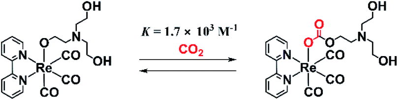 | (1) |
Recently, various supramolecular photocatalysts have been developed in which photosensitiser and catalyst units are connected to each other via a chemical bond.12–14 Some of the reported Ru(II)–Re(I) supramolecular photocatalysts (for example RuC2Re in Scheme 1) have been reported to be more efficient photocatalysts compared with a mixed system involving Ru(II) photosensitiser and Re(I) catalyst mononuclear complexes (Ru and Re).10,12,15–17 In photocatalytic CO2 reduction reactions using supramolecular photocatalysts with various Re(I) catalyst units such as Re(diimine)(CO)3Cl and [Re(diimine)(CO)2{P(p-F-C6H4)3}2]+, the CO2 adduct of the Re(I) catalyst unit is also produced in the initial stage of the photocatalytic reaction, which acts as the actual photocatalyst in CO2 reduction.18,19 In a system using the supramolecular photocatalyst with a carbonate ester ligand the photocatalytic reduction of CO2 proceeds efficiently in the Re catalyst unit even under a 10% CO2 atmosphere, with a similar quantum yield (Φ) and turnover number (TON) for the formation of CO compared with the reaction carried out under a 100% CO2 atmosphere. This type of supramolecular photocatalyst has recently been applied in various combined systems with solid materials, e.g., Z-scheme-type photocatalysts with semiconductor materials that can induce the photocatalytic reduction of CO2 using water as a reductant and only visible light as an energy source,20 and in a light-harvesting photocatalyst based on a mesoporous organosilica material.21
 | ||
| Scheme 1 Structures and abbreviations of the Ru(II)–Re(I) supramolecular photocatalyst and the model Ru(II) and Re(I) complexes, as well as the structure of BIH. | ||
Although fac-[Re(diimine)(CO)3(OC(O)OCH2CH2NR2)]-type complexes, including supramolecular photocatalysts, act as fascinating catalysts, several questions regarding their kinetics, thermodynamics, and mechanism in CO2 reduction, such as the process behind the formation of the OERS and its reactivity, remain unanswered. Clarification of these questions is important in the development of more efficient and durable photocatalytic systems for CO2 reduction.
In this study, the processes behind the formation of the OERS of RuC2Re and its reactivity using time-resolved infrared and visible (TR-IR and TR-vis) spectroscopy and electrochemical methods are examined.
Results and discussion
Photocatalysis of RuC2Re for CO2 reduction in DMSO–TEOA solution
To observe both the stretching bands of the CO ligands and the C![[double bond, length as m-dash]](https://www.rsc.org/images/entities/char_e001.gif) O group of the carbonate ester ligand in the supramolecular Ru(II)–Re(I) photocatalyst, when carrying out the Fourier-transform infrared (FT-IR) spectroscopic measurements, it is necessary to use a solvent that has a high transmittance in the absorption region of these vibrations, i.e., between 1600 and 2100 cm−1. N,N-Dimethylacetamide (DMA) and DMF containing TEOA mixed solutions, which have been commonly used in photocatalytic reactions involving Re(I) complexes as catalysts, barely transmit infrared light in some parts of this region. Thus, in this study, mixed dimethyl sulfoxide (DMSO)–TEOA (5
O group of the carbonate ester ligand in the supramolecular Ru(II)–Re(I) photocatalyst, when carrying out the Fourier-transform infrared (FT-IR) spectroscopic measurements, it is necessary to use a solvent that has a high transmittance in the absorption region of these vibrations, i.e., between 1600 and 2100 cm−1. N,N-Dimethylacetamide (DMA) and DMF containing TEOA mixed solutions, which have been commonly used in photocatalytic reactions involving Re(I) complexes as catalysts, barely transmit infrared light in some parts of this region. Thus, in this study, mixed dimethyl sulfoxide (DMSO)–TEOA (5![[thin space (1/6-em)]](https://www.rsc.org/images/entities/char_2009.gif) :1 v/v) and DMSO–tetrahydrofuran (THF)–TEOA (5:5:2 v/v) solutions were used, the transmittances of which are good enough to allow FT-IR measurements to be carried out (Fig. S1 in the ESI†). First, it was confirmed that RuC2Re exhibits sufficient photocatalytic activity in DMSO–TEOA solution. A CO2-saturated DMSO–TEOA (5:1 v/v) solution containing RuC2Re (0.05 mM) and 1,3-dimethyl-2-phenyl-2,3-dihydro-1H-benzo[d]imidazole (BIH, 0.1 M) as a sacrificial electron donor was irradiated at λex = 490–620 nm (λmaxex = 530 nm). Continuous and selective formation of CO was observed during the irradiation, as shown in Fig. 1a, with a very high turnover number (TONCO = 2100) and selectivity (ΓCO > 99%) of the formation of CO after 18 h of irradiation. The quantum yield of the production of CO (ΦCO) was determined to be 40% using 480 nm monochromatic light with a light intensity of 5.0 × 10⁻⁹ einstein s−1 (Fig. S2†). These results show that RuC2Re efficiently reduces CO2 to CO in DMSO–TEOA (5:1 v/v) with high selectivity and durability as well as in DMF–TEOA (5:1 v/v) and DMA–TEOA (5:1 v/v), which were used as solvents in previous studies.1,2,10–20
:1 v/v) and DMSO–tetrahydrofuran (THF)–TEOA (5:5:2 v/v) solutions were used, the transmittances of which are good enough to allow FT-IR measurements to be carried out (Fig. S1 in the ESI†). First, it was confirmed that RuC2Re exhibits sufficient photocatalytic activity in DMSO–TEOA solution. A CO2-saturated DMSO–TEOA (5:1 v/v) solution containing RuC2Re (0.05 mM) and 1,3-dimethyl-2-phenyl-2,3-dihydro-1H-benzo[d]imidazole (BIH, 0.1 M) as a sacrificial electron donor was irradiated at λex = 490–620 nm (λmaxex = 530 nm). Continuous and selective formation of CO was observed during the irradiation, as shown in Fig. 1a, with a very high turnover number (TONCO = 2100) and selectivity (ΓCO > 99%) of the formation of CO after 18 h of irradiation. The quantum yield of the production of CO (ΦCO) was determined to be 40% using 480 nm monochromatic light with a light intensity of 5.0 × 10⁻⁹ einstein s−1 (Fig. S2†). These results show that RuC2Re efficiently reduces CO2 to CO in DMSO–TEOA (5:1 v/v) with high selectivity and durability as well as in DMF–TEOA (5:1 v/v) and DMA–TEOA (5:1 v/v), which were used as solvents in previous studies.1,2,10–20 | (2) |
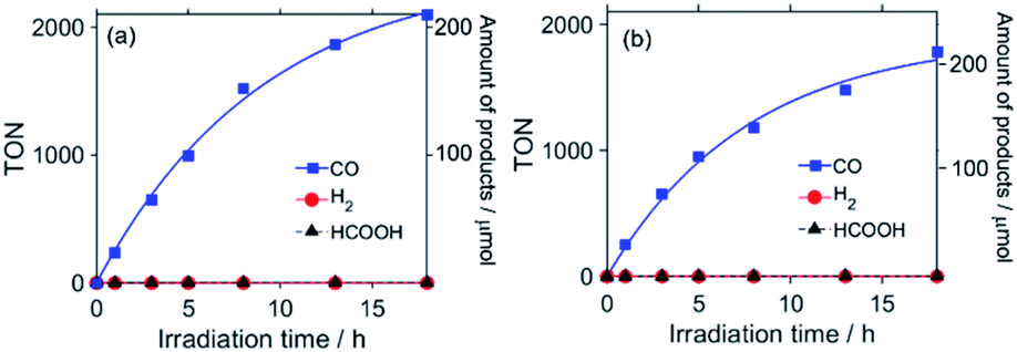 | ||
| Fig. 1 Photocatalytic formation of CO (blue), H2 (red), and formic acid (black) as a function of irradiation time. CO2-saturated (a) DMSO–TEOA (5:1 v/v) and (b) DMSO–THF–TEOA (5:5:2 v/v) solutions containing RuC2Re (0.05 mM) and BIH (0.1 M) were irradiated at λex = 490–620 nm. | ||
The photocatalytic reaction was monitored using 13CO2 by measuring the 1H and 13C nuclear magnetic resonance (NMR) spectra before and after irradiation. A 13CO2-saturated DMSO-d6 solution containing TEOA (1.26 M), RuC2Re (0.14 mM), and BIH (0.1 M) was irradiated in an NMR tube at λex = 490–620 nm (λmax = 530 nm) for 22 h. In the 1H NMR spectrum recorded before irradiation, peaks attributed to BIH (δ/ppm: 7.51–7.46 (m, 2H), 7.42–7.36 (m, 3H), 6.56 (dd, 2H, J = 5.5, 3.2 Hz), 6.38 (dd, 2H, J = 5.5, 3.2 Hz), 4.80 (s, 1H), and 2.42 (s, 6H)) were observed, but there were no peaks associated with its oxidised form (Fig. S3†). After the photocatalytic reaction, these peaks, which are related to BIH, decreased and new peaks that can be attributed to BI+ (δ/ppm: 8.06 (br, 2H), 7.88–7.68 (m, 7H), and 3.85 (s, 6H)) appeared. The concentrations of the reduced BIH and formed BI+, which is a two-electron oxidised and deprotonated compound of BIH (eqn (2)), are almost the same (0.086 M). In the 13C NMR spectrum (nuclear Overhauser effect, NOE, complete 1H-decoupling method) recorded after irradiation of the sample, peaks attributed to 13CO (δ = 184.8 ppm) and H13CO3− (δ = 156.8 ppm), which were not observed before irradiation, were observed (Fig. S4†). The integral ratio of the H13CO3− peak against the peaks of TEOA (1.26 M) as an internal standard for the integration was 2.01 ± 0.05. The concentration of H13CO3− produced during the irradiation was calculated using this value and the natural abundance of 13C in TEOA (1.07%), as shown in eqn (3).22
| [H13CO3−] = (2.01 ± 0.05) × [TEOA] × 3 × 0.0107 = 0.082 ± 0.002 M | (3) |
Thus, the amount of reacted BIH was found to be almost equivalent to the amount of H13CO3− produced. As previously mentioned, 13CO was detected in the 13C NMR spectrum of the reaction solution after irradiation. In a similar experiment using ordinary CO2 instead of 13CO2, the 13CO peak was not observed. Note at this point that most of the produced CO should be released into the gas phase in the NMR tube because of the relatively low solubility of CO. Hence, these results clearly demonstrate that one molecule of CO2 accepts two electrons from one molecule of BIH, with another CO2 molecule serving as the final O2− acceptor. Therefore, the overall reaction equation of the photocatalytic reaction using RuC2Re as a photocatalyst and BIH as a sacrificial electron donor in DMSO–TEOA is shown in eqn (4).
| 2CO2 + BIH → CO + HCO3− + BI+ | (4) |
Time-resolved spectroscopy
In the FT-IR spectrum of RuC2Re dissolved in DMSO–TEOA (5:1 v/v), recorded in an IR cell with an optical path length (d) of 0.2 mm, the stretching bands of the CO ligands can be clearly observed at 2018, 1911, and 1888 cm−1 and the CO stretching band of the carbonate ester ligand can also be observed at 1668 cm−1 (Fig. S5†). However, because of the relatively low transmittance of the solvent in the range of 1600–1700 cm−1 and some technical issues that arose during the measurements,23 the DMSO–TEOA (5:1 v/v) solvent was found to be not suitable for measuring the TR-IR spectra, for which an IR cell of d = 0.5 mm had to be used at these wavelengths. Hence, the solvent was diluted by adding THF, as it exhibits very high transmittance in the region of 1600–2100 cm−1, to produce DMSO–THF–TEOA (5:5:2 v/v), which was then used as a solvent to carry out the TR-IR measurements in an IR cell of d = 0.5 mm. Fig. 1b shows the formation of the reduction products in the photocatalytic reaction using RuC2Re in DMSO–THF–TEOA (5:5:2 v/v), under the same conditions as shown in Fig. 1a, except for the use of the different solvents to give TONCO > 1800 and ΓCO > 99%. This clearly indicates that RuC2Re is an efficient photocatalyst for CO2 reduction, even in DMSO–THF–TEOA. Fig. S7c† and 4c show the FT-IR spectra of RuC2Re in DMSO–THF–TEOA (5:5:2 v/v). The stretching bands of the CO ligands can be observed at 2019, 1913, and 1890 cm−1, besides the CO stretching band of the carbonate ester ligand at 1670 cm−1. The absorption band at 1619 cm−1 can be attributed to the stretching bands of the diimine ligands of Ru and Re. It has already been reported that the spectra of fac-Re(diimine)(CO)3-type complexes feature a diimine stretching band in this region.24 Actually, the spectra of Ru and Re feature this band at 1619 and 1621 cm−1, respectively (Fig. S6†). Notably, DMSO–TEOA (5:1 v/v) was mainly used as a solvent in the experiments to avoid concentration changes in the complex associated with CO2 bubbling, which volatilises the THF in the DMSO–THF–TEOA solutions.
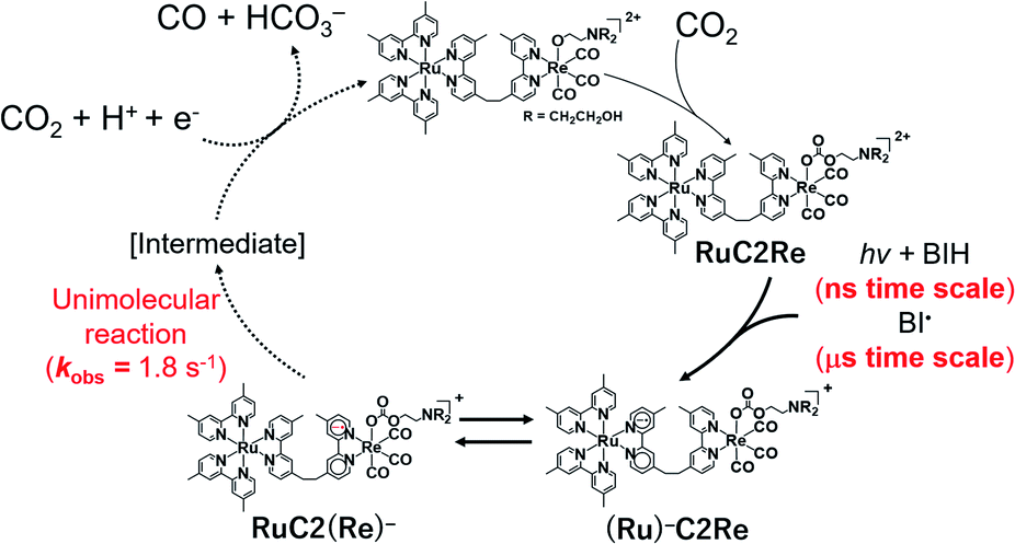
TR-IR measurements of CO2-saturated reaction solutions containing RuC2Re and BIH were performed using the pump–probe method applying the second harmonic (532 nm) of a Nd:YVO4 laser as the pump pulse. Fig. 2 and S7† display the TR-IR spectra in the region of the stretching vibrations of the CO ligands (1830–2050 cm−1) in DMSO–TEOA (5:1 v/v) and DMSO–THF–TEOA (5:5:2 v/v), respectively, in which it can be observed that virtually the same results were obtained in both solvents. Two sets of negative bleaching bands (νCO = 2017, 1913, and 1896 (sh) cm−1 in DMSO–TEOA; νCO = 2016, 1912, and 1896 (sh) cm−1 in DMSO–THF–TEOA) and two sets of new absorption bands attributed to a reaction intermediate shifted ∼25 cm−1 lower than the wavenumbers of the bleaching bands (νCO = 1993, 1880 (sh), and 1865 cm−1 in DMSO–TEOA; νCO = 1992, 1880 (sh), and 1864 cm−1 in DMSO–THF–TEOA) gradually appeared after the excitation. Bleaching bands were observed at similar wavenumbers to those of the ground state of RuC2Re (Fig. 2d and S7c†), which can be attributed to a decrease not only in the ground state of RuC2Re but also the excited state of the Ru unit (3(Ru)*C2Re) and the OERS of the Ru unit ((Ru)−C2Re). As shown in Scheme 2 these three states have similar νCO bands because of the weak interaction between the Ru and the Re units of this binuclear complex.25,26 These changes in the TR-IR spectra proceed via two steps, a fast process (Fig. 2a and S7a†) and a subsequent slower process (Fig. 2b and S7b†). The fast process proceeded for several of tens of nanoseconds after the excitation, which can be attributed to the production of RuC2(Re)−via reductive quenching of the excited state of the Ru unit (Process 1 shown in Scheme 2) followed by fast intramolecular electron transfer to the Re unit (Process 2 shown in Scheme 2). In the photocatalytic reduction of CO2 using RuC2Re and BIH in DMF–TEOA solution, we previously reported that BIH˙+ produced in Process 1 is deprotonated and converts to BI˙ (Process 3 shown in Scheme 2), which has a strong reducing power (Epox = −1.93 V vs. Ag/AgNO3 (−2.11 vs. Fc+/0)).16 Therefore, the slower process, which proceeded up to several microseconds in the DMSO–TEOA and DMSO–THF–TEOA solutions, can also be attributed to the reduction of ground state RuC2Re by BI˙ (Process 4 shown in Scheme 2). The UV-vis absorption spectra of Ru, Re, and RuC2Re shown in Fig. 3 clearly indicate that the intramolecular electronic interaction between the Ru and Re units is weak in the ground state as the RuC2Re spectrum can be well simulated via the summation of the Ru and Re spectra. Since the driving force of intramolecular electron transfer from the reduced Ru unit to the Re unit is estimated to be ΔGet = −30 meV, calculated from the difference between the first redox potentials of Ru (E(Ru/Ru−) = −1.63 V vs. Ag/AgNO3 (−1.81 V vs. Fc+/0)) and Re (E(Re/Re−) = −1.60 V vs. Ag/AgNO3 (−1.78 V vs. Fc+/0)) (Fig. S8† and 9(b)), the electron transfer from the OER Ru unit to the Re unit is slightly exergonic, and this intramolecular electron transfer should be reversible. These electron transfer reactions, which proceed via a through-bond mechanism, should be sufficiently faster than Process 4, i.e., the reduction of RuC2Re in its ground state by BI˙, and pseudo-equilibrium between (Ru)−C2Re and RuC2(Re)− was achieved within 60 ns (end of Process 1, Scheme 2) when the forward and reverse electron transfer rates became equal.25,26
 | ||
| Fig. 2 TR-IR spectra measured at the indicated time delay after pulsed 532 nm excitation, (a) up to 60 ns and (b) up to 24 μs. A DMSO–TEOA (5:1 v/v) solution containing RuC2Re (0.2 mM) and BIH (0.1 M) was irradiated using 532 nm pump light (50 Hz) and probed (100 Hz). (c) DFT-calculated TR-IR spectrum of Re− (10 cm−1 Gaussian full width at half maximum (FWHM)). (d) FT-IR spectrum of RuC2Re (6 mM) in DMSO–TEOA (5:1 v/v); d = 0.2 mm. | ||
 | ||
| Scheme 2 Production processes of a one-electron-reduced species by BIH. | ||
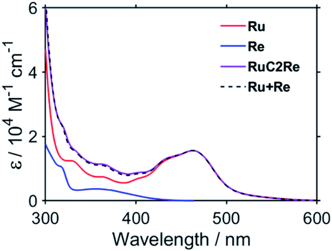 | ||
| Fig. 3 UV-vis absorption spectra of Ru (red), Re (blue), and RuC2Re (purple). The fitting result is shown as a dashed black line. | ||
Fig. 4a shows the TR-IR spectra of RuC2Re in the region of νCO of the carbonate ester ligand and the diimine ligand vibrations (1600–1750 cm−1) measured in DMSO–THF–TEOA. Two negative bands can be observed in the spectra at 1676 and 1622 cm−1 after the excitation, which can be attributed to the νCO of the carbonate ester ligand and the diimine ligands of RuC2Re, where the bleaching band of νCO (1676 cm−1) is shifted to a higher wavenumber compared with νCO (1670 cm−1, Fig. 4c), which indicates partial overlap of this negative peak with the positive band attributed to the νCO of the carbonate ester ligand of RuC2(Re)−, which forms on this timescale. As the reduction of the Re unit increases the electron density on the π* orbital of the carbonate ester ligand, it is predicted that the νCO of the carbonate ester ligand of RuC2(Re)− should shift to a lower wavenumber compared to that of RuC2Re. It can be expected that the overlap of the νCO bands of RuC2Re and RuC2(Re)− is a result of this small shift. Under the assumption that the shapes of the νCO absorption bands of the carbonate ester ligands of RuC2Re and RuC2(Re)− are the same, the 1630–1700 cm−1 region of the TR-IR spectrum was fitted using the FT-IR spectrum of RuC2Re, from which the νCO of the carbonate ester ligand of RuC2(Re)− was estimated to be 1664 cm−1 (Fig. S9†). This indicates that the νCO shift of the carbonate ester ligand caused by the OERS of the Re unit is only 6 cm−1 and is much smaller than that of the CO ligands (24 cm−1). These spectral results strongly suggest that the structure of the carbonate ester ligand of RuC2(Re)− is retained and that the additional electron is mainly localised on the diimine ligand in the Re unit. The corresponding positive band to the bleaching band at 1622 cm−1 cannot be observed between 1600 and 2100 cm−1, which should be red-shifted because of the increase in the electron density on the π* orbital of the diimine ligand(s).
 | ||
| Fig. 4 (a) TR-IR spectra measured at the indicated time delay after pulsed 532 nm excitation. A DMSO–THF–TEOA (5:5:2 v/v) solution containing RuC2Re (1.0 mM) and BIH (0.1 M) was irradiated with 532 nm pump light (50 Hz) and probed (100 Hz). (b) DFT-calculated TR-IR spectrum of Re− (10 cm−1 Gaussian FWHM; scaling factor = 0.965). (c) FT-IR spectrum of RuC2Re (3 mM) in DMSO–THF–TEOA (5:5:2 v/v); d = 0.5 mm. | ||
Density functional theory (DFT) was applied to support the assignment of the peaks of RuC2(Re)− observed in the TR-IR spectra. As the electronic interaction between the Ru and Re units is weak as described above, DFT calculations were performed for a model mononuclear complex of the Re unit, i.e., Re and its OERS Re−, to simplify the calculations. Fig. 2c and 4b show the calculated IR spectra, which are in good agreement with the TR-IR spectra, as can be observed in the data presented in Table 1. The singly occupied molecular orbital (SOMO) of Re− is mainly distributed on the diimine ligand (Fig. S10†). Mulliken analysis was performed to examine the difference in charge density between Re and Re− in more detail, with the results presented in Table S1.† The data obtained show that the most negatively charged ligand is the diimine. However, the charge densities at the carbonate ester bonds of Re and Re− are very similar, which is consistent with the slight shift in the νCO band of the carbonate ester ligand, and strongly supports the distribution of the added electron in RuC2(Re)− as described above. It is noteworthy that, because of the flexibility of the carbonate ester ligand, there are several possible stable structures of Re and Re−, with the calculations for all of the structures giving similar results, as shown in Fig. S11 and Table S2.†
:5:2 v/v) and DFT-calculated gas phase Re
| Calculated νCO (cm−1) of Re | Experimental νCO (cm−1) of RuC2Re | |
|---|---|---|
| Nonreduced state | 2011, 1915, 1902 (CO ligands) | 2019, 1913, 1890 |
| 1658 (carbonate ester) | 1670 | |
| One-electron-reduced state | 1985, 1878, 1852 (CO ligands) | 1992, 1880 (sh), 1864 |
| 1656 (carbonate ester) | 1664 (fitting result) |
Fig. 5 shows the TR-IR spectra measured on a longer timescale, i.e., up to 10 ms after excitation. It is noteworthy that, even after 10 ms, the νCO bands of the CO ligands do not change, although there is a gradual decrease in the intensities of the bleaching and positive bands. This decay in the bands is thought to be caused by the diffusion of the reduced species to the out of the probe light region due to the flow of the solution and/or the oxidation of the OERS by contaminated O2. These results strongly indicate that RuC2(Re)− is stable up to 10 ms, even under an atmosphere of CO2.
 | ||
| Fig. 5 TR-IR spectra measured at the indicated time delay after pulsed 526 nm excitation. A DMSO–TEOA (5:1 v/v) solution containing RuC2Re (0.2 mM) and BIH (0.1 M) was irradiated using 526 nm pump light (25 Hz) and probed (50 Hz). | ||
Fig. 6 shows the TR-vis absorption of a CO2 saturated DMSO–TEOA (5:1 v/v) solution containing RuC2Re and BIH measured using the randomly interleaved pulse train (RIPT) method applying the second harmonic (532 nm) of a Nd:YAG laser as the pump pulse.27 After the excitation, the absorption band at λmax = 519 nm was observed to increase in intensity. Although the broad absorption band at >580 nm also initially increased in intensity, it started to decrease in intensity 5 μs after the excitation (Fig. 6a). The absorption changes at 519 and 621 nm are shown in the spectrum in Fig. 7, in which the TR-IR behaviour of the absorbance at 1865 cm−1 of RuC2(Re)− can also be observed (Fig. 2b). The absorption at 519 nm was observed to increase in intensity immediately after excitation and then more slowly up to 30 μs, which corresponds to the temporal behaviour of the absorption at 1865 cm−1. Since the feature of the absorption band at λmax = 519 nm is similar to the previously reported results for the OERS of other Ru(II)–Re(I) supramolecular photocatalysts, it can be attributed to the absorption band of (Ru)−C2Re and RuC2(Re)−, of which the Ru unit or the Re unit is respectively reduced to its one-electron-reduced form.12,28 As the intramolecular electron transfers between the Ru and Re units of the OERS of RuC2Re (Processes 2 and 2′ in Scheme 2) proceed on the nanosecond timescale as described above, the equilibrium between them should be quickly reached and, afterward, the ratio between (Ru)−C2Re and RuC2(Re)− should not change. Although the ratio between (Ru)−C2Re and RuC2(Re)− could not be determined because of the molar extinction coefficients of the OERS of the Re unit not being known, it is thought that the [RuC2(Re)−]/[(Ru)−C2Re] ratio is greater than 1 because of the following reasons: (1) the shape of the absorption band is quite different from that of the OERS of Ru (Ru−) (Fig. S12†) and (2) the first reduction potential of Re (E1/2 = −1.60 V vs. Ag/AgNO3 (−1.78 V vs. Fc+/0) which is described in detail below) is more positive than that of Ru (E1/2 = −1.63 V vs. Ag/AgNO3 (−1.81 V vs. Fc+/0)). The slow increase in the growth of the absorption band at λmax = 519 nm can be attributed to another formation process of the OERS of RuC2Re, to which the electron donor is BI˙, because of the similarity in the timescale of the growth of the TR-IR absorption band at 1865 cm−1 attributed to RuC2(Re)− (Fig. 2b). Another absorption band at 621 nm was observed to grow for up to 5 μs after the excitation and then decreased as described above. This decay was observed to proceed on the same timescale as the second-step increase at 519 nm. The TD-DFT calculations in Fig. S13† show that this broadband can be attributed to BI˙, which is produced in Process 3, as shown in Scheme 2. The decay of this band proceeds on the same timescale as the slower growth of the absorption band at λmax = 519 nm, which validates Process 4 shown in Scheme 2, i.e., that the reduction of RuC2Re in the ground state by BI˙ proceeds on this timescale.
 | ||
| Fig. 6 TR-vis spectra at the indicated time delay recorded after 532 nm excitation of RuC2Re (0.2 mM) in a CO2-saturated DMSO–TEOA (5:1 v/v) solution containing BIH (0.1 M): (a) up to 50 μs and (b) up to 1.5 ms. | ||
 | ||
| Fig. 7 Temporal changes in ΔAbs at 519 and 621 nm (TR-vis, green and orange), and 1865 cm−1 (TR-IR, blue), normalised at 30 μs. | ||
Fig. 6b shows the TR-vis spectra measured on a longer timescale, i.e., up to 1.5 ms after excitation. The spectra show that the shape of the absorption band of the OERS of RuC2Re does not change between 50 μs and 1.5 ms after laser excitation, which means that the OERS of RuC2Re, i.e., (Ru)−C2Re and RuC2(Re)−, are stable on this timescale. This is consistent with the experimental TR-IR results.
UV-vis absorption spectral changes during and after steady-state irradiation
To elucidate the kinetics of the subsequent reaction of the one-electron-reduced Re unit, the following experiments were performed. A CO2-saturated DMSO–TEOA (5:1 v/v) solution containing RuC2Re (0.05 mM) and BIH (0.1 M) was irradiated under a 500 W xenon (Xe) arc lamp fitted with a bandpass filter at 2.6 × 10⁻⁸ einstein s−1 using strong steady-state light at 480 nm, much higher light intensity than that used in the photocatalytic reactions (see Fig. S2,† for example), and visible absorption spectral changes were measured during and after the irradiation. Fig. 8a shows the spectral changes that take place during the irradiation, in which a broad absorption band appears at λmax = 515 nm, which can be attributed to a mixture of (Ru)−C2Re and RuC2(Re)− according to similarity to the TR-vis results, shown in Fig. 6. This result indicates that the rate of production of the OERS is faster than the rate of the subsequent reaction of the OERS over this time period. The rate of accumulation of the OERS can be seen to decrease in line with the irradiation time. This is because the subsequent reaction is accelerated by the increase in the concentration of the OERS. When the irradiation was continued for 1.7 s and then stopped, the absorption band of the accumulated OERS began to decrease, as shown in Fig. 8b. Fig. 8c shows the temporal changes in ΔAbs at 519 nm, of which the decay curve can be well fitted using a single exponential function, where the observed first-order rate constant is kobs = 1.8 ± 0.1 s−1. We performed this experiment four times to determine the error in kobs. Since, in this experiment, the steady-state light was irradiated from only one direction and the solution was not stirred during the reaction, the reaction solution should reflect the concentration gradient of the OERS. To evaluate the effect that diffusion has on the concentration gradient, the same experiment was carried out, except that Ru was used instead of RuC2Re, the OERS (Ru−) of which is stable on this timescale. In this process, an argon-saturated DMSO–TEOA (5:1 v/v) solution containing Ru (0.05 mM) and BIH (0.1 M) was irradiated at 480 nm (5.3 × 10⁻⁹ einstein s−1) to accumulate Ru− (Fig. S14a†). Although the absorption band of the accumulated Ru− slowly decayed after the irradiation was stopped because of diffusion (Fig. S14b†), the rate of decay was approximately 37 times slower than that of the OERS of RuC2Re, as shown in Fig. 8c. Since the charges of the OERSs of RuC2Re and Ru are the same and the molecular radius of the OERS of RuC2Re is larger than that of Ru, the diffusion of the OERS of RuC2Revia a concentration gradient should be slower than that of Ru. Thus, the effect of diffusion is almost negligible when evaluating the rate constant of the subsequent reaction of RuC2(Re)−, which is k = 1.8 s−1. Note that this decay can be fitted using a first-order kinetics model but not using a second-order model. Hence, the disproportionation of the OERS of RuC2Re does not proceed as the main process of the subsequent reaction(s) of the OERS of RuC2Re.
 | ||
| Fig. 8 (a) Visible differential absorption spectra of RuC2Re (0.05 mM) in a CO2-saturated DMSO–TEOA (5:1 v/v) solution containing BIH (0.1 M) during irradiation at 480 nm (2.6 × 10⁻⁸ einstein s−1) (b) and after irradiation. (c) Temporal changes in ΔAbs at λ = 519 nm of RuC2Re (blue) and Ru (red, see Fig. S14 in the ESI†) during and after the irradiation. | ||
Electrochemistry
To examine the subsequent reaction of the one-electron-reduced Re unit in more detail, cyclic voltammograms (CVs) of Re as a model of the Re unit of RuC2Re were recorded at various scan rates in a CO2-saturated DMSO–TEOA (5:1 v/v) solution containing Re (1 or 2 mM) and tetraethylammonium tetrafluoroborate (Et4NBF4, 0.1 M) as a supporting electrolyte. At slow scan rates, e.g., 200 mV s−1 (Fig. 9a), an irreversible one-electron reduction wave at Ep = −1.66 V vs. Ag/AgNO3 (−1.84 V vs. Fc+/0) and a catalytic wave at Ecatp = −2.00 V (−2.18 V vs. Fc+/0) are observed. Fig. S15† shows the dependence of the scan rate on the first one-electron reduction wave of the process at Ep = −1.66 V vs. Ag/AgNO3 (−1.84 V vs. Fc+/0), in which it can be seen that upon increasing the scan rate, the process becomes more reversible. At 30 V s−1 using an ultra-micro glassy carbon working electrode, the first reduction wave is reversible and the Ered1/2 is −1.60 V vs. Ag/AgNO3 (−1.78 V vs. Fc+/0) (Fig. 9b). These results indicate that the subsequent chemical reaction of the OERS of Re, i.e., Re−, should proceed on the timescale of the CV experiments. Thus, the CVs of Re were fitted via digital simulation using an ALS/CHI620EX electrochemical analyser under the assumption that the process proceeds via an EC mechanism, as shown in eqn (5) and (6), where the background currents were subtracted from the CVs before the fitting. The fittings of the CVs were found to be reasonable, as shown in Fig. 10, with the rate constant of the chemical reaction of Re− (kc) determined as 2.1 s−1. | (5) |
 | (6) |
 | ||
| Fig. 9 (a) CV of Re (2 mM) in a CO2-saturated DMSO–TEOA mixed solution; WE: glassy carbon (diameter = 3 mm), RE: 0.01 mM Ag/AgNO3, CE: Pt wire, supporting electrolyte: 0.1 M Et4NBF4 (0.1 M), scan rate: 200 mV s−1, T = 298 K. (b) CV of Re measured in a DMSO–TEOA (5:1 v/v) solution under a CO2 atmosphere; WE: glassy carbon ultra-micro electrode (diameter = 33 μm), RE: 0.01 mM Ag/AgNO3, CE: Pt wire, supporting electrolyte: Et4NBF4 (0.1 M), scan rate: 30 V s−1. | ||
 | ||
| Fig. 10 Background subtracted CVs (red) and simulated CVs (black) of Re (1 mM); parameters: E1 = −1.60 V (ks = 0.1 cm s−1), kc = 2.1 s−1, D = 1.15 × 10⁻⁶ cm2 s−1. WE: glassy carbon (diameter = 3 mm), RE: 0.01 mM Ag/AgNO3, CE: Pt wire, supporting electrolyte: 0.1 M Et4NBF4 (0.1 M), scan rate: 200–1000 mV s−1, T = 298 K. | ||
Note that if the reduction potential of the intermediate produced by the subsequent reaction of Re− (eqn (6)) is close to or more positive than −1.60 V, the value of kc may be overestimated from its actual value because this intermediate is also reduced on the electrode, i.e., via an ECE mechanism; however, it does not induce a large difference in the value of kc. The calculated value is actually close to the experimental result using the steady-state light described above (k = 1.8 s−1). Also note that the kc value is not dependent on the concentration of Re in the solution. Additionally, both the reversibility of the first reduction wave and the value of kc are independent of the concentration of CO2 in the solution (Fig. S16†). Hence, CO2 is not involved in the subsequent reaction of Re−, and the disproportionation of the two molecules of Re− is also omitted from possible processes in CO2 reduction.
The first reduction wave of Re becomes more irreversible at a higher temperature, which indicates that the subsequent reaction of Re− is accelerated (Fig. S17†). Good linear Arrhenius plots were obtained, as shown in Fig. 11, and the activation energy of the subsequent reaction of Re− was obtained as Ea = 46 kJ mol−1. The results of the electrochemical measurements of Re can be summarised as follows. The lifetime of Re− was calculated to be ∼500 ms. Neither the disproportionation of Re− nor a bimolecular reaction between Re− and CO2 proceeds in the subsequent reaction of Re−. In other words, Re− reacts according to first-order kinetics, with an activation energy of Ea = 46 kJ mol−1. Note that the chemical properties of Re− and the reduced Re unit of RuC2(Re)− are similar to each other because of the weak interactions between the Ru and the Re units in RuC2Re. These results indicate that the subsequent reaction of RuC2(Re)− is a unimolecular reaction, such as the structural change of the reduced Re unit (Fig. 12).
 | ||
| Fig. 11 Arrhenius plot from which kc is derived. | ||
 | ||
| Fig. 12 Proposed mechanism of CO2 reduction using RuC2Re. | ||
Although we do not have conclusive evidence about the following processes including the structure of the intermediate produced by the unimolecular process of the one-electron reduced Re unit in RuC2(Re)−, we can presume a possible mechanism based on our experimental results and previously reported information as follows. Recombination of the carbonate ester ligand, i.e., change of the Re–O bond to a Re–C bond, followed by dissociation of a C–O bond gives the corresponding carboxylate Re complex [(diimine)(CO)3Re–C(O)OR] (R = C2H4N(CH2CH2OH)2 or H). Reduction of this complex might induce elimination of CO from the carboxylate ligand of the metal complex, which has been proposed in some photocatalytic and electrocatalytic CO2 reduction reactions using metal complexes as catalysts.5,8,29–31 This recombination mechanism is also supported by our previously reported linear relationships between CO formation rates and concentrations of the carbonate ester Re complexes in both photocatalytic and electrocatalytic CO2 reduction reactions. This relationship is maintained even under a low concentration of CO2 such as under Ar gas impregnated with only 0.5% CO2.
Another mechanism is elimination of the carbonate ester ligand from the one-electron reduced species of the Re complex giving a five-coordinated 17-electron species, i.e., [Re0(diimine)(CO)3]. Formation of a CO2 coordinated complex [ReII(diimine)(CO)3(CO2)] from the five-coordinated 17-electron species has been proposed in some photochemical CO2 reduction reactions using fac-[ReI(diimine)(CO)3L]n+-type complexes as catalysts.5,8 However, this elimination mechanism cannot explain the relationships between CO formation rates and concentrations of the carbonate ester Re complex as described above. In other words, this mechanism contradicts the previously reported high photocatalytic activity of the carbonate ester Re complexes even under a low concentration of CO2.
The identification of the real mechanism is in progress in our laboratory.
Conclusions
Efficient photocatalytic reduction of CO2 using RuC2Re as a photocatalyst and BIH as a sacrificial electron donor has been demonstrated to proceed in both DMSO–TEOA (5:1 v/v) and DMSO–THF–TEOA (5:5:2 v/v) solutions. The material balance of this photocatalytic reaction is shown in eqn (4), in which two molecules of CO2 and one molecule of BIH make one molecule each of CO, HCO3−, and BI+. The OERS RuC2(Re)−, as an essential intermediate in the photocatalytic reaction, is produced via two processes, namely, (1) the reductive quenching of the excited Ru unit followed by intramolecular electron transfer from the OERS of the Ru unit to the Re unit and (2) the reduction of RuC2Re in the ground state by BI˙, which is produced in process (1), followed by deprotonation. In RuC2(Re)−, the added electron is localised on the diimine ligand of the Re unit. Unimolecular reactions of RuC2(Re)− and its model mononuclear complex (Re−) proceed independently of the concentrations of CO2 and the reduced and unreduced complexes in the reaction solution. The subsequent reaction of RuC2(Re)− was found to proceed with an observed first-order rate constant of 1.8 s−1 at 298 K, which is not dependent on either the concentrations of CO2 or the OERS of RuC2Re. In the reaction of Re−, the activation energy, Ea, was estimated to be 46 kJ mol−1. Although the structure of the “second” intermediate in the photocatalytic reduction remains unknown, it has already been elucidated that the second electron injection process involving the intermediate, which is necessary for the formation of CO and HCO3− (eqn (4)), proceeds in two ways, i.e., via re-excitation of the Ru unit in the intermediate followed by reductive quenching and intramolecular electron transfer to the catalyst unit or via electron donation from reduced metal complexes, such as another intermediate made from the OERS of RuC2Re, or BI˙, which was elucidated in a previous study using a RuC2Re derivative fixed on an Al2O3 surface.32
Experimental
General procedures
1H and 13C NMR spectra were recorded using a JEOL ECA400II (400 MHz) spectrometer. The residual protons of acetonitrile-d3 and the 13C of TEOA were used as internal standards in these measurements. FT-IR and UV-vis absorption spectra were recorded using JASCO FT-IR 6600 and JASCO V-565 spectrophotometers, respectively. CVs were recorded on an ALS/CHI620EX electrochemical analyser using DMSO–TEOA (5:1 v/v) solutions containing Et4NBF4 (0.1 M) as a supporting electrolyte, a glassy carbon disc working electrode (diameter = 3 mm, 1 mm or 33 μm), a Ag/AgNO3 (0.01 M) reference electrode, and a Pt counter electrode. iR compensation was performed using the positive feedback method, which was implemented using the ALS/CHI620EX analyser.
Prior to its use in the measurements, DMSO was dried over 4 Å molecular sieves at room temperature, before being distilled in the presence of calcium hydride at reduced pressure. TEOA was distilled under reduced pressure (<133 Pa) prior to its use. After distillation, both solvents were stored under an Ar atmosphere. Et4NBF4 was dried under vacuum overnight at 100 °C prior to its use. All other reagents were of reagent grade quality and were used without further purification.
Synthesis
BIH and fac-[(dmb)2Ru(bpyC2bpy)Re(CO)3MeCN](PF6)2 (RuC2Re(MeCN), dmb = 4,4′-dimethyl-2,2′-bipyridine, bpyC2bpy = (4′-methyl-[2,2′-bipyridine]-4-yl)-CH2CH2-(4′-methyl-[2,2′-bipyridine]-4-yl)) were synthesised according to procedures published in the literature.19,33,34fac-[Re(dmb)(CO)3(CH3CN)]+ (Re(MeCN)) was prepared according to the method for the synthesis of fac-[Re(bpy)(CO)3(CH3CN)]+ described in the literature, except that fac-Re(dmb)(CO)3Br was used as a starting material.1
RuC2Re(MeCN) was dissolved in DMSO, and the resulting solution was kept at room temperature in the dark under an Ar atmosphere for 4 h for changing the MeCN ligand of all of the added Re complexes to the DMSO ligand because TEOA attacks the MeCN ligand of the Re complexes and an imino ester ligand is produced.9 After this time, TEOA was added into the solution (DMSO:TEOA = 5:1 v/v), which was kept under an Ar atmosphere in the dark at room temperature for a period of more than 5 h. The resulting solution was bubbled with CO2 to give a DMSO–TEOA (5:1 v/v) solution containing RuC2Re.
To synthesise a DMSO–TEOA (5:1 v/v) solution containing Re, the above method for RuC2Re was followed with Re(MeCN) used in place of RuC2Re(MeCN).
Photocatalytic reactions
To carry out TON measurements, DMSO–THF–TEOA (5:5:2 v/v, 2.4 mL) or DMSO–TEOA (5:1 v/v, 2 mL) solutions containing RuC2Re (0.05 mM) and BIH (0.1 M) in 11 mL volume Pyrex test tubes were purged with CO2 for 20 min and then irradiated at 490–620 nm (λmax = 530 nm) using an Iris-MG merry-go-round irradiation instrument equipped with a light-emitting diode (LED) light source (CELL System Co.). To carry out quantum yield measurements, in an 11 mL necked quartz cubic cell (path length: 1 cm), a CO2-saturated DMSO–TEOA (5:1 v/v, 4 mL) solution containing RuC2Re (0.05 mM) and BIH (0.1 M) was irradiated at λex = 480 nm (5.0 × 10⁻⁹ einstein s−1) using a 300 W Xe lamp (Asahi Spectra MAX-303) equipped with a bandpass filter in a Shimadzu QYM-01 photoreaction quantum yield evaluation system. The sample temperature was kept at 25 °C ± 0.1 °C using an IWAKI CTS-134A temperature bath. The gaseous products, i.e., CO and H2, and formic acid in the solution were analysed via gas chromatography using a TCD (GL Sciences GC323) and a capillary electrophoresis system (Agilent Technologies 7100L), respectively.
Labelling experiments using 13CO2
An NMR tube containing a DMSO-d6 solution, TEOA (1.26 M), RuC2Re (0.14 mM), and BIH (0.1 M) was deaerated three times via a freeze–pump–thaw method, before adding 13CO2 (537 mmHg). The 1H and 13C NMR spectra were measured before and after irradiation for 22 h using the same light source used in the photocatalytic reactions. The integration of the peaks using the NOE complete 1H-decoupling method (EXMOD: nne, scan: 115, relaxation time: 400 s) was applied to determine the concentration of H13CO3−, using the carbon in TEOA as an internal standard. The long relaxation time minimized the effects of NOE. The relaxation time should be 5 times longer than 13C spin–lattice relaxation times (T1) for integration.35 Since T1 of HCO3− was reported to be 10 s or less,36 400 s which we used as the delay time should be long enough for this measurement.UV-vis absorption spectra during irradiation
In the case of RuC2Re, a CO2-saturated DMSO–TEOA (5:1 v/v) solution containing RuC2Re (0.05 mM) and BIH (0.1 M) in an 11 mL necked quartz cubic cell (path length: 1 cm) was irradiated at λex = 480 nm (2.6 × 10⁻⁸ einstein s−1) using a 500 W Xe arc lamp equipped with a bandpass filter. In the case of Ru, an Ar-saturated DMSO–TEOA (5:1 v/v) solution containing Ru (0.05 mM) and BIH (0.1 M) in an 11 mL necked quartz cubic cell (path length: 1 cm) was irradiated at λex = 480 nm (5.3 × 10⁻⁹ einstein s−1) using a 500 W Xe arc lamp equipped with a bandpass filter. The temporal changes in the UV-vis absorption spectra were measured using a Photal MCPD-9800 photodiode array spectrometer (Ohtsuka Electronics Co., Ltd.). The sample temperature was kept at 25 °C ± 0.1 °C using an IWAKI CTS-134A temperature bath.
TR-vis spectroscopy
TR-vis spectroscopic measurements were performed using a picoTAS-ns-W2 picosecond transient absorption spectroscopy system (UNISOKU Co., Ltd.), operated using the RIPT method and a flow cell system (light pass length: 0.2 cm), as shown in Fig. S18.† A CO2-saturated DMSO–TEOA (5:1 v/v) solution containing the complex and BIH (0.1 M) was irradiated using Nd:YAG laser pulses at λex = 532 nm (pulse width < 350 ps: 5 Hz).
TR-IR spectroscopy
TR-IR spectroscopic measurements were performed using a pump–probe method applying a subnanosecond laser for the pump pulse and a femtosecond Ti:sapphire laser for the probe pulse. The details of this procedure have been reported previously in the literature.37–39 A tunable mid-infrared probe pulse was generated using a combination of optical parametric amplification and difference frequency generation (Light Conversion Ltd. Topas Prime, tunable range: 2500–12000 nm; pulse energy: 40 μJ per pulse; bandwidth: 150 cm−1) from a portion of the output of a femtosecond Ti:sapphire chirped-pulse amplifier (Spitfire Ace, Spectra-Physics; pulse duration: 120 fs; central wavelength: 800 nm; repetition rate: 1 kHz). The visible pump pulse was obtained by generating the second harmonic (532 nm) of a Nd:YVO4 laser (InnoLas Laser Co. Picolo-AOT picosecond Nd:YVO4 laser system; wavelength: 1064 nm; pulse duration: 0.6 ns) or the second harmonic (526.5 nm) of a laser (TECH-1053 basic diode-pumped Q-switched laser, Laser-export Co.; wavelength: 1053 nm; pulse duration: 10 ns) using an LBO crystal. The pump pulse was synchronised to the probe light via a function generator. The function generator reduced the repetition of a trigger pulse to 100 Hz. The fluence of the pump pulse was approximately 7 mJ cm−2. The time control of the pump light and the probe light was performed by digitally controlling the delay using the function generator. The pump light and the probe light were focused to a FWHM of 220 and 200 μm, respectively. The probe light transmitted through the sample cell was guided to a polychromator (Horiba Co. TRIAX 190) coupled with a multichannel MCT array detector system (Infrared Systems Development FPAS-6416-D). The MCT detector was electronically gated at 100 Hz and was synchronised to the pulse generator, which prevents the detection of the unnecessary probe light. A homemade solution cell composed of BaF2 window plates and a 0.5 mm Teflon spacer was filled with the sample solution. The samples were prepared as follows: CO2 was bubbled into 20 mL of DMSO–TEOA (5:1 v/v) or DMSO–THF–TEOA (5:5:2 v/v) solutions containing the complex for 1 h. After the bubbling process was complete, BIH (448 mg, 0.1 M) was added to the solutions and additional CO2 bubbling was conducted for approximately 15 min before carrying out the TR-IR measurements. CO2 bubbling was continued during the measurements. In the case of the DMSO–THF–TEOA (5:5:2 v/v) solution, CO2-saturated THF was added every 10 min to compensate for the concentration changes that arise because of the volatilisation of THF.
Quantum chemical calculations
Quantum chemical calculations based on DFT were performed using the Gaussian 16 package.40 Vibrational spectra were calculated after geometry optimisation of the ground and OER states. The LanL2DZ basis set and M06 functional were used to compare the calculated and experimental TR-IR spectra. Time-dependent DFT (TDDFT) calculations of the excited states were also performed in DMSO solution using the general basis set of 6-311G++(d,p) used for geometry optimisation.Digital simulation
The digital simulations of the CVs were performed by using an ALS/CHI620EX electrochemical analyser. Diffusion coefficients and E1/2 values were determined from the CVs, assuming a heterogeneous rate constant of 0.1 cm s−1. The rate constant of the chemical reaction (kc) was determined by fitting the background subtracted CVs measured at various scan speeds.Data availability
All the data supporting this article have been included in the main text and the supplementary material.Author contributions
K. Kamogawa: most of experiments, writing of manuscript. Y. Shimoda: TR-IR measurements, DFT calculations. K. Miyata: TR-IR measurements, DFT calculations. K. Onda: TR-IR measurements, DFT calculations, writting of the TR-IR part. Y. Yamazaki: discussion. Y. Tamaki: supervision of experiments, discussion. O. Ishitani: conceptualization, funding acquisition, and supervision; writing, review, and editing of manuscript.Conflicts of interest
There are no conflicts to declare.Acknowledgements
This work was supported by JSPS KAKENHI Grant Numbers JP20H00396 and JP17H06440 in Scientific Research on Innovative Areas “Innovations for Light-Energy Conversion (I4LEC)”.Notes and references
- (a) J. Hawecker, J.-M. Lehn and R. Ziessel, J. Chem. Soc., Chem. Commun., 1983, 536–538 Search PubMed; (b) J. Hawecker, J.-M. Lhen and R. Ziessel, Helv. Chim. Acta, 1986, 69, 1990–2012 Search PubMed.
- (a) H. Hori, F. P. A. Johnson, K. Koike, O. Ishitani and T. Ibusuki, J. Photochem. Photobiol., A, 1996, 96, 171–174 Search PubMed; (b) H. Takeda, K. Koike, H. Inoue and O. Ishitani, J. Am. Chem. Soc., 2008, 130, 2023–2031 Search PubMed.
- (a) T. Morimoto, C. Nishiura, M. Tanaka, J. Rohacova, Y. Nakagawa, Y. Funada, K. Koike, Y. Yamamoto, S. Shishido, T. Kojima, T. Saeki, T. Ozeki and O. Ishitani, J. Am. Chem. Soc., 2013, 135, 13266–13269 Search PubMed; (b) J. Rohacova and O. Ishitani, Chem. Sci., 2016, 7, 6728–6739 Search PubMed.
- (a) Y. Kuramochi, O. Ishitani and H. Ishida, Coord. Chem. Rev., 2018, 373, 333–356 Search PubMed; (b) Y. Tamaki, H. Takeda and O. Ishitani, in Molecular Technology, ed. H. Yamamoto and T. Kato, Wiley-VCH Verlag GmbH & Co. KGaA, 2019, vol. 1, pp. 209–249 Search PubMed.
- Y. Kou, Y. Nabetani, D. Masui, T. Shimada, S. Takagi, H. Tachibana and H. Inoue, J. Am. Chem. Soc., 2014, 136, 6021–6030 Search PubMed.
- Y. Hayashi, S. Kita, B. S. Brunschwig and E. Fujita, J. Am. Chem. Soc., 2003, 125, 11976–11987 Search PubMed.
- J. Agarwal, E. Fujita, H. F. Schaefer and J. T. Muckerman, J. Am. Chem. Soc., 2012, 134, 5180–5186 Search PubMed.
- T. W. Schneider, M. Z. Ertem and J. T. Muckerman, ACS Catal., 2016, 6, 5473–5481 Search PubMed.
- T. Morimoto, T. Nakajima, S. Sawa, R. Nakanishi, D. Imori and O. Ishitani, J. Am. Chem. Soc., 2013, 135, 16825–16828 Search PubMed.
- T. Nakajima, Y. Tamaki, K. Ueno, E. Kato, T. Nishikawa, K. Ohkubo, Y. Yamazaki, T. Morimoto and O. Ishitani, J. Am. Chem. Soc., 2016, 138, 13818–13821 Search PubMed.
- H. Kumagai, T. Nishikawa, H. Koizumi, T. Yatsu, G. Sahara, Y. Yamazaki, Y. Tamaki and O. Ishitani, Chem. Sci., 2019, 10, 1597–1606 Search PubMed.
- B. Gholamkhass, H. Mametsuka, K. Koike, T. Tnabe, M. Furue and O. Ishitani, Inorg. Chem., 2005, 44, 2326–2336 Search PubMed.
- Y. Tamaki, K. Koike, T. Morimoto, Y. Yamazaki and O. Ishitani, Inorg. Chem., 2013, 52, 11902–11909 Search PubMed.
- Y. Kuramochi and O. Ishitani, Inorg. Chem., 2016, 55, 5702–5709 Search PubMed.
- Y. Tamaki and O. Ishitani, ACS Catal., 2017, 7, 3394–3409 Search PubMed.
- Y. Tamaki, K. Koike, T. Morimoto and O. Ishitani, J. Catal., 2013, 304, 22–28 Search PubMed.
- A. M. Cancelliere, F. Puntoriero, S. Serroni, S. Campagna, Y. Tamaki, D. Saito and O. Ishitani, Chem. Sci., 2020, 11, 1556–1563 Search PubMed.
- E. Kato, H. Takeda, K. Koike, K. Ohkubo and O. Ishitani, Chem. Sci., 2015, 6, 3003–3012 Search PubMed.
- K. Ohkubo, Y. Yamazaki, T. Nakashima, Y. Tamaki, K. Koike and O. Ishitani, J. Catal., 2016, 343, 278–289 Search PubMed.
- (a) H. Kumagai, G. Sahara, M. Higashi, R. Abe and O. Ishitani, Chem. Sci., 2017, 8, 4242–4249 Search PubMed; (b) G. Sahara, H. Kumagai, K. Maeda, N. Kaeffer, V. Artero, M. Higashi, R. Abe and O. Ishitani, J. Am. Chem. Soc., 2016, 138, 14152–14158 Search PubMed.
- Y. Ueda, H. Takeda, T. Yui, K. Koike, Y. Goto, S. Inagaki and O. Ishitani, ChemSusChem, 2015, 8, 439–442 Search PubMed.
- *NIST Physical Measurement Laboratory, http://www.nist.gov/pml/data/comp.cfm.
- The FT-IR cell with d = 0.2 mm was too thin to allow the DMSO–TEOA (5:1 v/v) solution to flow because of its high viscosity. Although we could solve this problem by increasing the thickness of the flow IR cell to d = 0.5 mm and all of the stretching bands of the CO ligands were measurable even when using this thick cell, the absorbance of the solvent was too high for the CO stretching band of the carbonate ester ligand to be measured.
- S. Sato, Y. Matubara, K. Koike, M. Falkenström, T. Katayama, Y. Ishibashi, H. Miyasaka, S. Taniguchi, H. Chosrowjan, N. Mataga, N. Fukuzawa, S. Koshihara, K. Onda and O. Ishitani, Chem.–Eur. J., 2012, 18, 15722–15734 Search PubMed.
- K. Koike, D. C. Grills, Y. Tamaki, E. Fujita, K. Ohkubo, Y. Yamazaki, M. Saigo, T. Mukuta, K. Onda and O. Ishitani, Chem. Sci., 2018, 9, 2961–2974 Search PubMed.
- Y. Yamazaki, K. Ohkubo, D. Saito, T. Yatsu, Y. Tamaki, S. Tanaka, K. Koike, K. Onda and O. Ishitani, Inorg. Chem., 2019, 58, 11480–11492 Search PubMed.
- T. Nakagawa, K. Okamoto, H. Hanada and R. Katoh, Opt. Lett., 2016, 41, 1498–1501 Search PubMed.
- S. Sato, K. Koike, H. Inoue and O. Ishitani, Photochem. Photobiol. Sci., 2007, 6, 454–461 Search PubMed.
- M. D. Sampson, J. D. Froehlich, J. M. Smieja, E. E. Benson, I. D. Sharp and C. P. Kubiak, Energy Environ. Sci., 2013, 6, 3748–3755 Search PubMed.
- J. A. Keith, K. A. Grice, C. P. Kubiak and E. A. Carter, J. Am. Chem. Soc., 2013, 135, 15823–15829 Search PubMed.
- H. Ishida, K. Tanaka and T. Tanaka, Organometallics, 1987, 6, 181–186 Search PubMed.
- D. Saito, Y. Yamazaki, Y. Tamaki and O. Ishitani, J. Am. Chem. Soc., 2020, 142, 19249–19258 Search PubMed.
- E. Hasegawa, T. Seida, N. Chiba, T. Takahashi and H. Ikeda, J. Org. Chem., 2005, 70, 9632–9635 Search PubMed.
- X.-Q. Zhu, M.-T. Zhang, A. Yu, C.-H. Wang and J.-P. Cheng, J. Am. Chem. Soc., 2008, 130, 2501–2516 Search PubMed.
- P. Giraudeau, J. L. Wang and E. Baguet, C. R. Chim., 2006, 9, 525–529 Search PubMed.
- H. Yamada, F. A. Chowdhury, K. Goto and T. Higashii, Int. J. Greenhouse Gas Control, 2013, 17, 99–105 Search PubMed.
- T. Mukuta, N. Fukazawa, K. Murata, A. Inagaki, M. Akita, S. Tanaka, S. Koshihara and K. Onda, Inorg. Chem., 2014, 53, 2481–2490 Search PubMed.
- T. Mukuta, S. Tanaka, A. Inagaki, S. Koshihara and K. Onda, ChemistrySelect, 2016, 1, 2802–2807 Search PubMed.
- T. Mukuta, P. Simpson, J. G. Vaughan, B. W. Skelton, S. Stagni, M. Massi, K. Koike, O. Ishitani and K. Onda, Inorg. Chem., 2017, 56, 3404–3413 Search PubMed.
- M. J. Frisch, G. W. Trucks, H. B. Schlegel, G. E. Scuseria, M. A. Robb, J. R. Cheeseman, G. Scalmani, V. Barone, G. A. Petersson, H. Nakatsuji, X. Li, M. Caricato, A. V. Marenich, J. Bloino, B. G. Janesko, R. Gomperts, B. Mennucci, H. P. Hratchian, J. V. Ortiz, A. F. Izmaylov, J. L. Sonnenberg, D. Williams-Young, F. Ding, F. Lipparini, F. Egidi, J. Goings, B. Peng, A. Petrone, T. Henderson, D. Ranasinghe, V. G. Zakrzewski, J. Gao, N. Rega, G. Zheng, W. Liang, M. Hada, M. Ehara, K. Toyota, R. Fukuda, J. Hasegawa, M. Ishida, T. Nakajima, Y. Honda, O. Kitao, H. Nakai, T. Vreven, K. Throssell, J. A. Montgomery Jr, J. E. Peralta, F. Ogliaro, M. J. Bearpark, J. J. Heyd, E. N. Brothers, K. N. Kudin, V. N. Staroverov, T. A. Keith, R. Kobayashi, J. Normand, K. Raghavachari, A. P. Rendell, J. C. Burant, S. S. Iyengar, J. Tomasi, M. Cossi, J. M. Millam, M. Klene, C. Adamo, R. Cammi, J. W. Ochterski, R. L. Martin, K. Morokuma, O. Farkas, J. B. Foresman, and D. J. Fox, Gaussian 16, Revision A.03, Gaussian, Inc., Wallingford CT, 2016 Search PubMed.
Footnotes |
| † Electronic supplementary information (ESI) available. See DOI: 10.1039/d1sc02213j |
| ‡ Present address: Department of Materials and Life Science, Graduate School of Science and Engineering, Seikei University, 3-3-1 Kichijoji-kitamachi, Musashino-shi, Tokyo 180-8633, Japan. |
| This journal is © The Royal Society of Chemistry 2021 |