
 Open Access Article
 This Open Access Article is licensed under a
 Creative Commons Attribution 3.0 Unported Licence
Perspective on intermetallics towards efficient electrocatalytic water-splitting
Carsten
Walter
 ,
Prashanth W.
Menezes
* and
Matthias
Driess
*
,
Prashanth W.
Menezes
* and
Matthias
Driess
*
Derpartment of Chemistry: Metalorganics and Inorganic Materials, Technische Universität Berlin, Strasse des 17. Juni 135, Sekr. C2, Berlin 10623, Germany. E-mail: prashanth.menezes@mailbox.tu-berlin.de; matthias.driess@tu-berlin.de
First published on 8th June 2021
Abstract
Intermetallic compounds exhibit attractive electronic, physical, and chemical properties, especially in terms of a high density of active sites and enhanced conductivity, making them an ideal class of materials for electrocatalytic applications. Nevertheless, widespread use of intermetallics for such applications is often limited by the complex energy-intensive processes yielding larger particles with decreased surface areas. In this regard, alternative synthetic strategies are now being explored to realize intermetallics with distinct crystal structures, morphology, and chemical composition to achieve high performance and as robust electrode materials. In this perspective, we focus on the recent advances and progress of intermetallics for the reaction of electrochemical water-splitting. We first introduce fundamental principles and the evaluation parameters of water-splitting. Then, we emphasize the various synthetic methodologies adapted for intermetallics and subsequently, discuss their catalytic activities for water-splitting. In particular, importance has been paid to the chemical stability and the structural transformation of the intermetallics as well as their active structure determination under operating water-splitting conditions. Finally, we describe the challenges and future opportunities to develop novel high-performance and stable intermetallic compounds that can hold the key to more green and sustainable economy and rise beyond the horizon of water-splitting application.
 Carsten Walter | Carsten Walter obtained his PhD in 2019 from Technische Universität Berlin, Germany, under the supervision of Prof. Matthias Driess and Dr Prashanth W. Menezes on the bioinspired heterogeneous catalysts for water oxidation. He is currently working as a post-doctoral research fellow in the same group and his research interests include the synthesis of functional materials for application in electrocatalytic water splitting and their structure–activity relationship. |
 Prashanth W. Menezes | Prashanth W. Menezes received his PhD in 2009 from the Max Planck Institute for Chemical Physics of Solids in Dresden, Germany, in solid-state and structural chemistry. He then joined the Technische Universität München in 2010 to work in the direction of inorganic chemistry with a focus on novel materials. In 2012, he joined the Driess group at the Technische Universität Berlin and since then serves as a group leader for inorganic materials. His research focuses on the design, development, properties, and (surface) structural understanding of novel unconventional catalysts in heterogeneous catalysis, especially in the area of redox oxygen catalysis, (photo)electrocatalytic water splitting as well as electrochemical redox reactions. |
 Matthias Driess | Matthias Driess is a full professor of metalorganics and inorganic materials at the Department of Chemistry of Technische Universität Berlin. He obtained his PhD degree and completed his habilitation at the University of Heidelberg in Germany. He serves as a deputy of the Cluster of Excellence UniSysCat and is a Director of the UniSysCat-BASF SE joint lab BasCat, and of the Chemical Invention Factory (CIF) for Start-ups in Green Chemistry. He is a member of the German National Academy of Sciences (Leopoldina), the Berlin-Brandenburg Academy of Sciences and Humanities, and the European Academy of Sciences. |
1. Introduction
The rising global demand for energy is experiencing major challenges with its exponential growth and nearly entire dependency on fossil fuels.1 Depletion of these natural resources and the inconvenient impact on climate with its carbon emissions stipulate alternative strategies in energy supply.2 In the last few years, tremendous efforts have been dedicated to fulfil the required energy demand by renewable and green technologies and are expected to continue to grow in the years to come.3 In this regard, hydrogen (H2) is considered as an abundant and clean fuel that can be used as a chemical energy store with a minimal loss of energy.4,5 H2 has the highest chemical energy per mass with 143 MJ kg−1 (ref. 6) and its energy density is three times higher than that of diesel or gasoline (47 MJ kg−1). Once produced, H2 is a clean synthetic fuel, energy supplier for households and the economy, and an important raw material for the chemical industry.6,7 A practical and attractive approach to produce inexpensive, reliable, and highly pure H2 is electrochemical water splitting.8,9 Depending on the pH value of the electrolyte, water splitting is realized with a polymer electrolyte membrane (PEM) electrolyzer in acidic conditions, neutral water or with alkaline electrolyzer (AEC), and at high temperatures with neutral water with solid oxide electrolysis (SOEL).10 Generally, these technologies are referred to as water electrolyzer cells (WEC) and considered as the most promising technologies for power-to-(P2G) gas conversion.3,10 WECs have their own characteristic merits and shortcomings depending on the process conditions, efficacy, materials, and purity of the product. So far, SOEL has shown the highest efficiency of the WEC technologies but demands challenging material properties due to its high-temperature process of 700–900 °C.10Alternatively, PEM technology provides high energy efficiency and fast H2 production rate with high purity, however, impedes their catalyst scope mainly to precious metal and metal oxides resulting in the high cost and limiting their widespread industrial application.10,11 In comparison to PEM, an AEC is considered the mellow approach and has widely been used as the leading technology in large-scale industrial applications.10,12 Mediating H2 evolution in alkaline media allows replacing noble metals with earth-abundant materials, that either are not stable in acidic conditions or only show poor activities.13 Therefore, AECs have attracted research to explore various 3d transition metals as alternative catalysts for benchmarking noble-metal IrOx, RuOx, and Pt systems.14,15
Over the years, to bring the WECs to cost parity, numerous classes of cost-effective electrocatalysts such as metal oxides/(oxy)hydroxide,16 chalcogenides,17,18 pnictides,19,20 phosphates,21 phosphites,22 borophosphates,23,24 borides,25 selenides,26 carbides,27 alloys,28 and their heterostructures, have been reported either as cathodes or anodes and a majority of them have shown promising results in comparison to the state-of-the-art catalysts. The reason for superior activity is often described as the presence of a higher number of active sites on the surface, better reaction kinetics as well as the modified electronic properties. In this regard, intermetallic compounds possess complex structures with distinct chemical bonding and have already been found applications in magnetism, superconductivity, shape-memory effects, H2 storage, and recently even for heterogenous catalysis.29 Due to covalent bonds, intermetallics are considered as (electro-)chemical stable with high electric conductivity. The high activity is often related to a high number of active sites resulting from the highly ordered structure with voids.30 These enhanced attractive physical, chemical, and electronic properties with suitable element specificity in intermetallic compounds have attracted considerable interest as ideal electrocatalysts for water splitting.
In this perspective, we focus on the most recent advances in electrocatalytic water-splitting with intermetallic materials (Scheme 1). First of all, we present the fundamental understanding of electrocatalytic water splitting and its evaluation parameters. Next, in order to give the readers a conception of the development methodologies, we discuss the underlying aspects as well as advanced synthetic strategies in detail. Subsequently, we review the electrocatalytic performance of numerous noble-metal and non-noble metal-based intermetallic compounds that have been tested for water splitting in acidic, neutral, and alkaline media. Special emphasis has been given to the understanding of the nature of precatalyst and active catalysts, their modifications, electronic modulations, and structure–activity relation under reaction conditions. In the end, we highlight the future perspectives and challenges of intermetallic compounds for water splitting as well as we provide some proposed topics that are potentially interesting for future research. We consider that this perspective will provide valuable guidelines and deep insights into the field and will also inspire many to research a similar direction.
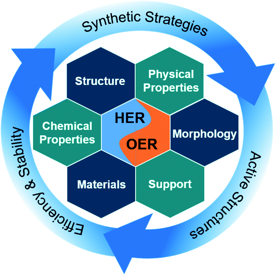 | ||
| Scheme 1 Intermetallics for water splitting describing the synthesis strategies to access intermetallic materials with different morphological, structural, chemical, and physical properties with diverse elemental composition. This includes insights into active structure and the reasons for their high efficiency and stability in electrochemical water spitting. | ||
2. Electrochemical water-splitting
For hydrogen production by electrochemical conversion of water to oxygen and hydrogen, the free energy of ΔG = 238 kJ mol−1 is needed to mediate the reaction (eqn (1)).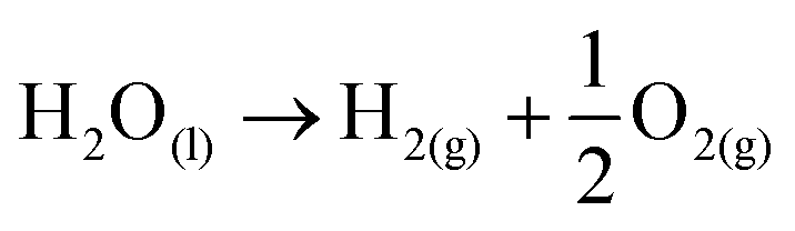 | (1) |
Although it is seemingly a simple straightforward reaction adjunct to plain electrochemistry, the energy loss entangled to mechanistic intricacy demands strenuous efforts to facilitate water splitting.1,31
2.1 Fundamentals
Water splitting is divided into two half-reactions, water reduction at the cathode for the hydrogen evolution reaction (HER) and water oxidation for oxygen evolution reaction (OER) at the anode.32,33Cathode (HER):
| 2H+ + 2e− → H2E0Red = 0.00 V | (2) |
Anode (OER):
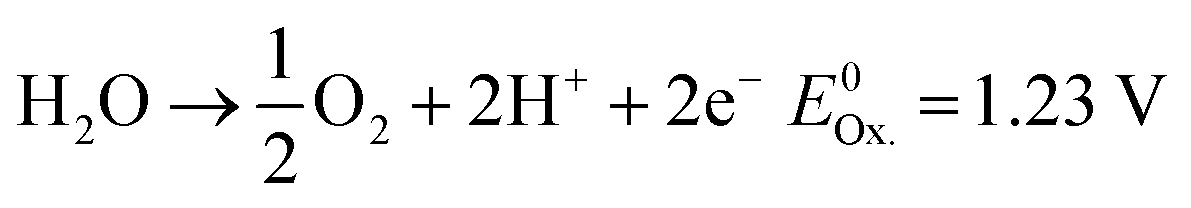 | (3) |
OER in particular requires significantly more energy than HER due to comparably more intermediates and reaction steps.34 Accounting for the sluggish uphill reaction, OER is still referred to as the bottleneck of overall water splitting, and that is why, in the last few years, immense efforts have been dedicated to seek alternative materials that can effectively reduce the kinetic limitation of OER and enable optimal reaction conditions.21 Both reactions take place at the electrode surface (anode and cathode) together with the electrolyte and require consideration of the inner and outer Helmholtz layers.35 The performance of these reactions can be measured separately using electrochemical techniques, which can be used to determine the exact values of the applied potentials.36 In this regard, the electrochemical HER and OER can be expressed in terms of two redox pairs. In OER, the reduced form H2O and the oxidized form O2 form the redox couple (O2/H2O).2 The HER is composed of the reduced form H2 and the oxidized form H+ to form the redox couple (H+/H2). Each of both redox systems have different degrees of reducing and oxidizing power as described in the eqn (2) and (3)2 and can be described electrochemically by the redox potential E of the redox system.2 The redox potential can be described mathematically by the Nernst equation (see eqn (13)):37
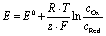 | (4) |
The constant z describes the number of electrons occurring in the redox system and R is defined as the general gas constant.36 The standard potentials are characteristic of each redox system and cannot be determined experimentally. They form a parameter for the strength of the reducing or oxidizing effect of such a system and thus indicate whether electrons are taken up or released.36,38 Only the total potential of a galvanic element can be measured and the potential difference between two redox pairs can be determined to a reference.36
2.2 Reaction mechanisms
The HER is kinetically favored and takes place relatively thermodynamically uninhibited with the formation of the single intermediate M–Hads which requires ideally a binding energy of 0 V.41,42 Its kinetics are defined by two intermediate steps with three possible pathways, the Volmer, and the Heyrovsky or Tafel step with two-electron transfers (see eqn (5)–(7), Fig. 1a).32,43,44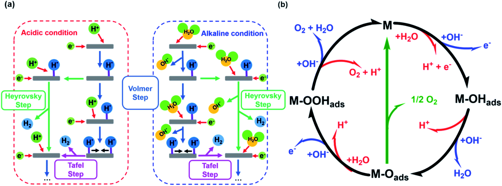 | ||
| Fig. 1 (a) HER mechanism in acidic and alkaline conditions with the Volmer reaction (blue), Heyrovsky reaction (green), and Tafel reaction (purple). Adapted with permission from ref. 39 copyright 2018, Springer Nature (b) OER mechanism for acidic (red) and alkaline (blue) conditions. The black line shows the OER pathway via an active site with the M–OOHads intermediate. The alternative pathway via two M–Oads intermediates is shown in green. Adapted with permission from ref. 40, copyright 2017, RSC Publishing. | ||
Volmer:
| M + H2O + e− → M–Hads + OH− | (5) |
Heyrovsky:
| M–Hads + H2O + e− → M + H2 + OH− | (6) |
Tafel:
| M–Hads + M–Hads → 2M + H2 | (7) |
The second step depends on the surface concentration of active sites. On surfaces with low concentrations of active sites, the Heyrovsky reaction is preferred (eqn (6)). In this case, a second water molecule is adsorbed at the same active site followed by electron transfer and desorption of dihydrogen and a hydroxyl ion.45 The Tafel reaction is the dominant mechanism on catalyst surfaces with a high concentration of active sites. Chemical desorption of dihydrogen is mediated by two active sites close to each other. The distance between the two active sites should not be more than the van der Waals radius of two adsorbed hydrogen atoms, the closer they are more likely this reaction path occurs.45
The mechanism of the OER is thermodynamically more demanding than for HER with complex kinetics that varies depending on the pH of the electrolyte and the catalyst material (Fig. 1b).46 The fourfold is the limiting factor in this reaction, which contains at least three intermediates.40,47 There are several pathways discussed in the literature for varying mechanisms under alkaline and acidic conditions.13,48–51 For the OER under alkaline conditions, the oxide pathway or the electrochemical oxide pathway with two active sites and single-site catalysis have been established (eqn (8)–(10)).45,52
| M + OHaq− → M–OHads + e− | (8) |
| M–OHads + OHaq− → M–Oads + H2O + e− | (9.1) |
| M–OHads + M–OHads → M–Oads + M + H2O + e− | (9.2) |
| M–Oads + OHaq− → M–OOHads + e− | (10) |
The last step is often described as proceeding concerted, but can also be divided into two intermediate-steps and proceed via the M–OOads− intermediate, which determines the overall reaction rate (eqn (11) and (12)).40,52
| M–OOHads + OHaq− → M–OOads− + H2O | (11) |
| M–OOads− → M + O2 + e− | (12) |
The proposed mechanisms for one or two active sites differ only slightly and include the same intermediates as M–OHads and M–Oads.40,52 The main difference is the final O–O bond formation and release of dioxygen.40 The reaction via two catalytically active sites takes place through two M–Oads intermediates with a direct combination of both to form 2M and O2 (eqn (13)).
| M–Oads + M–Oads → 2M + O2 | (13) |
Ideally, the binding of the intermediates requires 1.23 eV each, so that free energy of 4.92 eV is required for all four proton-coupled electron transfer (PCET) steps.2 All formed intermediates (M–OHads, M–Oads, M–OOHads, M–OOads−) influence the kinetics of the reaction and have a limiting effect on the reaction rate (higher overpotential) if the adsorption or desorption or formation of the respective intermediate proceeds energetically unfavorably.52 The route via a single active site with the formation of the M–OOads− intermediate as discussed above is rarely found in the literature but is taken into account for investigations of kinetic barriers during OER.52 Despite these differences, there is mutual consensus about the crucial importance of bond interactions in M–O within these intermediates (M–OHads, M–Oads, M–OOHads, M–OOads−). The M–O bond characteristics of the active species M are essential for the overall electrocatalytic activity.40
2.3 Activity evaluation criteria
The activity parameters are the most important criteria to evaluate the activity, efficiency, and stability of a catalyst. The overpotential of an electrochemical process is the additional potential required to catalyze the intended reaction at the thermodynamically determined reversible potential (E0) under ideal conditions.53 Typically the overpotential η at a current density of 10 mA cm−2 (η10) derived from CVs or LSVs is used as a benchmark to compare the activities of electrocatalysts and corresponds to the ∼10% solar-to-chemicals efficiency.54,55 On the other hand, because of the tremendous growth in the field, researchers have now started to evaluate and compare η100 and η500 in addition to η10 which is highly recommended if a catalyst reaches high current densities. In this way, the evaluation of a catalyst activity would be closer to industrial application standards.The description of the catalyst activity via the Tafel slope provides a lot of information about the properties of the catalyst material and is recommended to measure under steady-state conditions.56 The Tafel slope can provide insights into the dynamics of the catalytic processes taking place on the surface and provide information about kinetics and inhibitions during the water oxidation catalysis.52 It indicates how much the potential has to increase in order to increase the resulting (measured) current j by an order of magnitude.52 It is an indication of how efficiently and dynamically an electrode or the catalyst applied to it, reacts to an applied potential and generates a catalytic current. This also takes into account any changes in the mechanism with different η and can be used to determine which of the PCET reaction in the mechanism is the rate-determining step.2,45,57
During the HER, the Volmer step is the RDS when the reaction is defined by the adsorption and discharge of H+ on the catalyst surface, which is indicated by a Tafel slope of ∼120 mV dec−1 (eqn (5)).45 In the case of a low Hads concentration on the surface, the Heyrovsky step is dominant (eqn (6)). A second H+ will be adsorbed at the same active site followed by discharge and desorption of H2 and is indicated by a Tafel slope of ∼40 mV dec−1. If the Hads concentration on the surface is high, a direct combination of the intermediates is possible to generate H2 (eqn (7)) and resulting in a Tafel slope of ∼30 mV dec−1.52 For the OER process, a Tafel slope of 120 mV dec−1 indicates that the overall reaction kinetics is dominated by the coordination of the hydroxide step (eqn (8)).57 A Tafel slope of 40 mV dec−1, indicates the RDS of the electrochemical formation of M–Oads (eqn (9.1)).57,58 Alternatively the M–Oads formation can proceed via two metal centers indicated by a Tafel slope of 30 mV dec−1 (eqn (9.2)). If the reaction is determined by the formation and desorption of O2, a Tafel slope of 15 mV dec−1 is expected (eqn (13)).57
On the other hand, theoretical modelling has suggested that a Tafel slope of 120 mV dec−1 is not necessarily accompanied by the Volmer step as RDS. Kinetic studies based on microkinetic analysis gave the same Tafel slope for different elementary steps based on intermediate coverage on the surface and mass transport effects. Especially considering newly proposed radical coupling mechanisms rather than a single-site mechanism for OER.52 Further, Liu and co-workers suggested based on calculations that the thermodynamic-kinetic model is also highly dependent on factors such as binding environments, temperature, and electrolyte pH that should also be accounted into the design strategy for catalysts.59
Electrochemical impedance spectroscopy (EIS) is also a powerful tool to investigate mechanisms in electrochemical reactions, charge transfer processes in materials, and surface properties of electrodes.60 It provides very precise results on the electrical conductivity of a material and is a frequently based technique.38 From the obtained impedance spectra, conclusions can be drawn about the ability of materials to store electrical energy and transfer electrical charge.61 The electrodes are measured with a two or three-electrode set-up where the potentiostat transmits an alternating potential with varying frequency (ω) to the sample. By generating a signal proportional to the generated current. An analyzer then determines the impedance Z of the system from the alternating current flowing through the sample and the alternating voltage generated by a generator.61 Similarly, the determination of the electrochemically active surface (ECSA) is an in situ method, which determines the number of active centers responsible for the respective reaction on the surface (AECSA) and thus their size.62–64 Other ex situ methods such as BET65 measurement (BET = Brunauer Emmett Teller) to determine the surface area by adsorbing gas molecules such as nitrogen (N2) can be problematic particularly in the case of porous structures since the accessibility to the interior of the structure depends on the size of the adsorbed molecule.62 Surfaces determined with N2 can be smaller than with krypton or water and provide different results than surfaces determined with ECSA.62,66 Both analytical methods to evaluate the surface of the catalyst have their own merits and disadvantages and should be considered carefully. While the BET does not necessarily correspond to the ECSA and could result in an unfair comparison between catalysts with different surface densities of active sites, the ECSA analysis suffers from inaccuracies due to the yet non-trivial determination of the roughness factor.13 Therefore, it is highly recommended to represent activity plots normalized to both BET and ECSA. In addition to the activity indicators, the long-term stability of the system is also a crucial parameter considering their use for commercial applications. This is typically measured via cyclic voltammetry (CV), galvanostatic chronoamperometry (CA) or potentiostatic chronopotentiometry (CP) electrolysis measurement.
Another valuable insight is the faradaic efficiency (FE), which is defined as the efficiency of electron transfer provided by the external circuit to promote the electrochemical HER or OER reaction. At a constant current density applied for a certain period of time of the experiment, a gas sample is taken with a gas-tight syringe and analyzed with a gas chromatograph (GC) calibrated for H2 or O2. The faradaic efficiency is then calculated from the volume of the generated gas during electrocatalysis, in comparison to the current over time and gives directly correlates the number of electrons needed to generate a mole of gas.67–69 The turnover frequency (TOF) is another important descriptor to evaluate the catalytic activity which provides the generated H2 or O2 molecules per second at a single active site. However, the precise determination of TOF remains challenging due to the complexity involved in identifying the total number of such active sites and therefore, only a rough estimation is possible.15
By calculations of density functional theory (DFT), potential materials suitable for HER and OER can be identified and sorted according to their catalytic activity based on the adsorption (ΔEH) and binding energy (ΔG) of the above-discussed intermediates.70,71 According to the derived calculations from the DFT, a close relationship between the overpotential and ΔG of the surface adsorbed intermediates can be expressed. With a few exceptions, DFT provides good predictions about the OER and HER activity of the materials.3 For instance, if ΔGHads ≈ 0 then the material should possess the optimal binding strength for the intermediate and is considered as a good catalyst for HER. But if is ΔG < 0, Hads is bound too strong and desorption of H2 is the RDS shifting kinetics via the Heyrovsky or Tafel mechanism.53 A ΔG > 0 indicates a too weakly bounded Hads and therefore, the kinetics is limited by the adsorption of the intermediate, and the reaction proceeds via the Volmer step.53 DFT calculations have also been applied to study the relationships of ΔG in each individual reaction pathway and the activity for both alkaline and acidic media.72
3. Introduction to intermetallics
Intermetallic compounds belong to the class of alloys but are distinct by the difference between the subclasses on how the atoms are ordered in the crystalline phase.73 The bonding in intermetallics involves the combination of partly ionic or covalent interactions instead of weak metallic bonds making them an ordered lattice. Depending on their structure, alloys are initially classified into two different categories: as a solid solution or as an intermetallic compound (Fig. 2).29 Solid solutions alloys with metal species of similar atomic radius, electronic character, and crystal structure identical to that of the parent metal form a substitutional solid solution with a statistical distribution of the atoms on the lattice sites (Fig. 2a).29 If the atomic radius of an element is sufficiently small to fit into the lattice spaces of the parent metal, an interstitial solid solution forms (Fig. 2b). In these cases, the composition in the degree of mixing can vary almost at will.29,74 Based on a linear interpolation between the properties of the parent materials, the same physical properties can be expected in the resulting alloy.74 The situation is different when two metals A and B to form an intermetallic compound (Fig. 2c). Intermetallic phases are specified by a clearly defined stoichiometric composition of the elements such as AB, AB2, A3B, or even complex mixtures such as A6B23.74 Ideally, the metals A and B are not randomly distributed but are arranged at specific positions in the unit cell and differ for A and B.74 This often results in physical properties that are distinct from the physical properties of the composite elements with a well-ordered crystal structure disparate from those of the parent elements.74,75 Hence, a semiconductor can be derived from two metallic conductors in an intermetallic phase, or a magnetic intermetallic phase can be formed from non-magnetic composing materials.74,76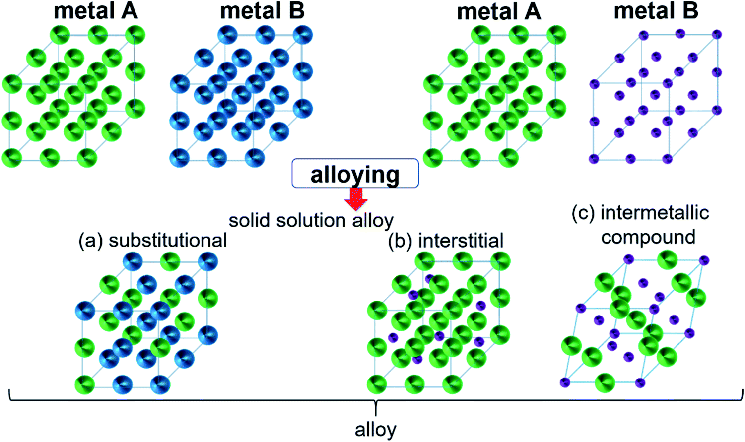 | ||
| Fig. 2 Formation of structures of bimetallic compounds in a solid phase when alloyed: (a) substitutional and (b) interstitial solid-solution alloys and (c) intermetallic compound. Adapted with permission from ref. 29, copyright 2016, American Chemical Society. | ||
Intermetallic systems have the advantage that a heterogeneous catalytic process such as the adsorption of reactants on the catalyst surface or the activation of reactants mediating the reaction to the desired target product can be assigned to the suitable incorporated species which can cooperate via so-called interfaces in the composite material. When it comes to composite materials, intermetallics have a particularly large number of interfaces between the different types of atoms in their structure. A particularly pronounced synergism between activation of the reactants on the surface by one metal and realization of the reaction by fine-tuning of the redox potential with the help of the other can be achieved.77 The synergetic effect of the two metallic components improves the properties compared to the individual homometallic components.
Recently, it has been shown that most of the compounds containing anions/nonmetals are unstable under water splitting conditions (especially in OER) and depending on the testing period, they transform either partially or completely to their corresponding mostly layered oxide/oxyhydroxide structures. Such surface/bulk transformed materials from non-oxidic materials have proven to be more active compared to the bare oxide materials due to either high ECSA leading to higher accessible active sites or better electronic conductivity. As the intermetallic compounds are element specific with complex crystal structures and can be formed by both active and conducting elements, they are naturally considered good candidates for electrocatalytic water splitting.
4. Chemical synthetic strategies of intermetallics
Most of the so far known 6000 binary intermetallics are mainly derived from solid-state techniques since they have been primarily investigated for their physical and structural properties.74,76,78 Intermetallic compounds often show increased stability, selectivity, and activity for a variety of catalytic processes due to their complex structure and bonding characteristics,73,76,79 and therefore, over the years, many new advanced synthetic approaches to control their particle size, shape, morphology, and surface area have been developed to gain wider adoption.30,76 In the following, several important strategies for the synthesis of intermetallics, starting from single crystals to nanostructures, towards catalytic HER and OER have been discussed in detail.4.1 High-temperature solid-state methods
A historical approach to the synthesis of intermetallics is the thermal annealing method in a protective atmosphere or evacuated conditions at relatively high temperatures to produce thermodynamically stable products in large single crystals from μm up to mm scale.80 Though little control remains of the reaction pathway during synthesis (temperature, pressure), and often exploratory efforts are required to attain the desired phase-pure and functional compounds.80,81 Giving access to a broad variety of metallic alloy and intermetallic phases, this method is often used to study materials for their physical, chemical, and mechanical properties.82–86 The benign technique to develop and predesign intermetallic precursors for the catalytic application has given rise to a large number of water-splitting electrocatalysts.87–90For instance, Lasia and co-workers synthesized Ni–Mo91 and Ni–Mo–Al92 based intermetallic phases for HER of various compositions by mixing the elemental powders in stoichiometric amounts and melted under an inert atmosphere. While mixing Ni with Mo gave phase pure Ni4Mo and Ni3Mo, the Ni–Mo–Al phase was a mixture of Ni2Al3 or Ni2Al3/NiAl3 with NiAl5Mo2.91,92 Similarly, a phase pure Ni3Al was prepared in vacuum at temperatures between 600–1250 °C by the group of Liu using commercially available Ni carbonyl and gas atomized Al powder as precursors. The resulting material of a highly porous morphology showed excellent performances in HER catalysis.93,94 Meanwhile, Ni3Al prepared by Han et al. in vacuum at a temperature of 1000 °C using the induction melting technique showed good activity during electrocatalytic OER.95
Along this direction, mixing elemental Al and Co metal powders followed by heating in the Ar atmosphere resulted in the formation of an intermetallic nanoporous Al9Co2 framework that after additional sulfurization acted as a highly efficient precatalyst for HER.96
Motivated by the previous results, we recently synthesized polycrystalline MnGa4 by annealing a stoichiometric mixture of Mn and Ga in an evacuated quartz ampule to 900 °C for four days to ensure homogeneity of the mixture, then cooled down and annealed at 380 °C for further ten days.97 Identical conditions were also chosen to prepare Fe6Ge5 from Fe powder and Ge chips where the stoichiometric amount of metals were sealed at 1000 °C for two days before annealing again at 650 °C for seven days.98 Both intermetallic phases were examined for catalytic OER in alkaline conditions that showed significant activity and stability.97,98 In addition, through solid–gas reaction from a mixture of copper and nickel powders, a highly conductive antiperovskite-based hybrid Cu1−xNNi3−y was synthesized and after Fe3+ treatment, the formation of a p-Cu1−xNNi3−y/FeNiCu with a core–shell structure was observed. Such rational design of the catalyst displayed high conductivity and porosity resulting in a remarkable activity towards OER (Fig. 3a).99
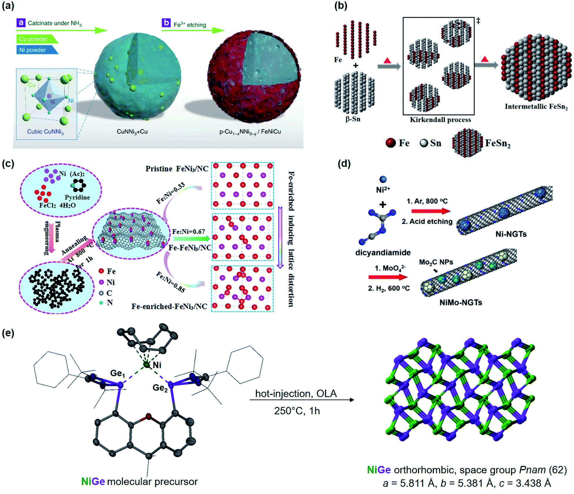 | ||
| Fig. 3 (a) Schematic representation of the synthesis of p-Cu1−xNNi3−y/FeNiCu by solid–gas reactions of CuNNi3 + Cu and NH3 followed by Fe3+ etching. Reprinted with permission from ref. 99, copyright 2018, Nature Publishing Group (b) illustration of the formation of intermetallic FeSn2 and close packing of the individual atomic layers of Fe and Sn (tetragonal, I4/mcm) via the Kirkendall process. Adapted with permission from ref. 102, copyright 2020, Wiley-VCH (c) synthesis and the fabrication procedure of FeNi3/NC, Fe–FeNi3/NC and Fe-enriched-FeNi3/NC. Reprinted with permission from ref. 103, copyright 2020, Elsevier (d) illustrated synthesis protocol of NiMo-NGTs. Reprinted with permission from ref. 104, copyright 2016, American Chemical Society (e) synthesis of NiGe from the molecular bis(germylene)-Ni complex. Adapted with permission from ref. 105, copyright 2020, Wiley-VCH. | ||
The solid-state techniques have been further extended for the preparation of intermetallic phases containing five or more metal elements with high entropic order. Jin et al. were successfully synthesized Al97Ni1Co1Ir1 and Al96Ni2Ir2 by melting using an induction-melting furnace under Ar protection.100 Subsequently, the prepared phases were melted again in a quartz tube and injected onto a spinning Cu roller to prepare the ribbons that were then chemically etched in a 0.5 M NaOH solution to prepare nanoporous high-entropy alloys (np-HEAs) for the HER catalysis.100 Very similarly, Ding et al. designed a quinary FeCoNiCrNb0.5 from their corresponding elemental powders. The eutectic high entropy alloy (EHEA) with a porous nanostructure and high corrosion resistance was successfully applied as a catalyst for OER.101
Apart from using traditional induction furnaces and overcome their limitations, arc-melting became a viable method to rapidly (re)melt and refine structures as well as remove high and low-density inclusions during melting.106 It is a quite simple and straightforward technique and has widely been applied to attain various noble, i.e. PtDy,107 Al2Pt108 and non-noble metal-based, i.e. Ti2Ni,87 TiCo2,109 Ni2Ta110 intermetallic compounds for HER and OER. Along this line, lamellar nanostructured Ni–Co–Al was prepared by arc melting the homogenized raw materials at 1200 °C under Ar atmosphere that showed convincing results for alkaline HER.111 In a similar approach, the noble metal-based Hf2B2Ir5 phase was obtained via a two-step process in which the metals were first arc melted in Ar at about 1200 °C for several weeks and then applied through spark plasma sintering (SPS) to retrieve the electrode material for OER catalysis.112 Moreover, in a unique strategy, Jian and co-workers synthesized nanoporous hybrid Cu12−x−yCoxMoyAl88 (x![[thin space (1/6-em)]](https://www.rsc.org/images/entities/char_2009.gif) =0 or 3, y=0 or 1) electrodes by arc melting pure Cu, Al, Co, and Mo metals in an Ar atmosphere and successively chemically-etched them in a N2-purged 6 M KOH electrolyte at 70 °C for 3h. The synthesized electrodes were successfully applied for overall water splitting, while the OER electrodes were additionally electrochemically oxidized in a dealloying step at 1.57V vs. RHE for 20min under alkaline conditions.113
=0 or 3, y=0 or 1) electrodes by arc melting pure Cu, Al, Co, and Mo metals in an Ar atmosphere and successively chemically-etched them in a N2-purged 6 M KOH electrolyte at 70 °C for 3h. The synthesized electrodes were successfully applied for overall water splitting, while the OER electrodes were additionally electrochemically oxidized in a dealloying step at 1.57V vs. RHE for 20min under alkaline conditions.113
4.2 Chemical reduction
A relatively mild approach at ambient pressure and low temperature is the chemical reduction of metallic precursors in adequate solvents. Varying the reducing agents from the low reducing power of ethanol and linoleic acid to strong with NaBH4 and N2H4 gives control over unwanted reactions where noble metals have dominated the reduction process leading to core–shell structures. With the additional use of surfactants and the specific choice of solvents, various noble and non-noble nanoparticles (NPs), e.g. FeIr3, NiPd, CoPd2, CuRh, NiPt, etc., can be prepared, with varying size and shape from hexagonal or star-shaped to spherical and even small network-like structures.115–117 Compared to solid-state, this approach allows overcoming the kinetics energy barrier in the disorder-to-order transition at lower temperatures (<350 °C) allowing structure transition into a well-defined nanoparticular system with proposed composition.118 To improve the catalytic activity of catalysts for water splitting, the active sites must have an optimal balance between adsorption and dissociation of intermediates, high electronic conductivity, cost, and stability. Therefore, the chemical reduction is an efficient technique to modulate the electronic structure, reduce or inhibit noble metal content, modify morphology and surface on the atomic level.118Taking advantage of this approach, nano particular PdBi2119 and Pd3Pb114 on Pt were prepared that showed the potential of nanoscale surface engineering by modifying rather inactive materials into highly efficient HER catalysts (Fig. 4). Both systems were attained at relatively mild conditions below 200 °C giving highly ordered NPs with improved intrinsic activity.114,119 Concurrently, IrNi and IrPt nanoframes were synthesized by reducing corresponding metal salt precursors and etching the framework. The as-attained IrNi systems encompassed a high ECSA and improved intrinsic activity compared to bare Ir. Not only was IrNi more active than bare Ir towards OER, but it also showed improved long-term stability mediating the challenging reaction in acidic media.120
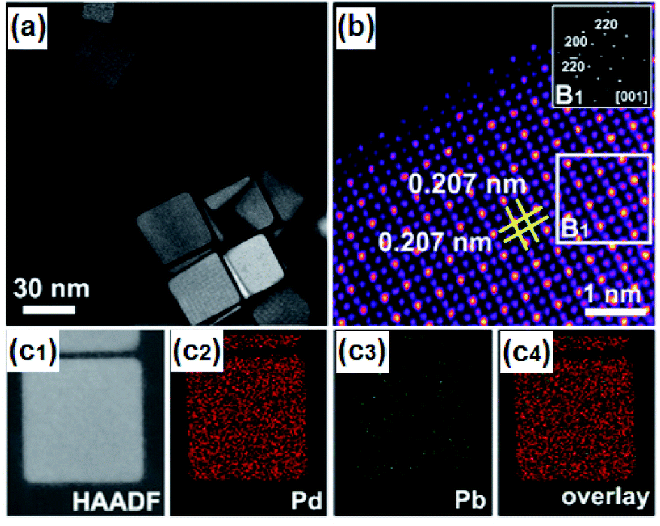 | ||
| Fig. 4 (a) HAADF-STEM image of Pd3Pb with (b) atomic-resolution HAADF-STEM image and FFT pattern in the inset, and (c1–c4) EDS mappings of Pd3Pb. Reprinted with permission from ref. 114, copyright 2019, American Chemical Society. | ||
At moderately high temperatures, we prepared the intermetallic FeSn2 phase by reducing a stirred mixture of iron(III) and tin(II) salt in a solution of polyethylene glycol and ethylene glycol under a rapid and constant flow of N2. The growth of intermetallic FeSn2 nanocrystals transpired by the interspersing of Fe into the interlayers of metallic Sn through a Kirkendall process (Fig. 3b).102 An analogous one-pot reduction was also used to prepare isotypic CoSn2 nanocrystals at 170 °C.97 Both materials were tested for water splitting catalysis with very high activity for both OER and HER.97,102
The hot injection is another viable reduction technique to synthesize monodisperse NPs, via rapid nucleation, followed by controlled growth of nuclei to form larger particles, and is well developed for the preparation of quantum dots. By varying stabilizing ligands, precursors, reaction time, and temperature, various phases of different sizes and morphologies can be achieved.121 In this respect, for the synthesis of popcorn-shaped GaPt3 NPs, Lim et al. used Ga(C5H7O2)3 precursor in oleylamine (OLA) and preheated to 200 °C under Ar atmosphere. To this solution, PtI2 was injected, and the mixture was heated up to 280 °C for 30 min followed by an instant cooling in a cold water bath. The intermetallic GaPt3 phase was examined for HER in all pH ranges (alkaline, acidic, and neutral).122 Alternatively, Lim et al. used the hot-injection method to prepare GaPd2 nanomaterials with different morphology such as polyhedrons, NPs, and nanowires just by using different solvents that exhibited both high catalytic HER activity and stability and were far superior to a commercial Pd catalyst.123 Furthermore, the same group synthesized GePt3 and Ge2Pt and concluded that by tuning the composition of the solvents and reagents as well as the reaction temperature, distinct phases of intermetallic compounds active for HER can be realized.124 In the meantime, Schaak and co-workers reported a lower-temperature route to colloidal metal silicide NPs such as Pd2Si, Ni2Si, and Cu3Si that were efficient for HER in acidic media.125
4.3 Hydro(solvo)thermal route
Hydrothermal or solvothermal synthesis is generally defined as a chemical reaction occurring at aqueous or non-aqueous solvents at elevated temperatures above the boiling point of the reaction medium and above atmospheric pressure. This synthetic technique is rather straightforward compared to the high-temperature solid-state and requires mostly moderate temperatures. By controlling the suitable selection of reaction conditions (precursor composition, pH, solvent, heating rate, temperature, pressure, concentration, etc.), pure phases with distinct sizes and morphology can be obtained. Currently, this method has been regarded as one of the versatile and relatively simple approaches to access numerous amorphous and crystalline structures.81Although a variety of intermetallic compounds have been synthesized under such conditions and applied for manifold applications, their utilization as electrocatalysts for water splitting is rather limited.126–129 Recently, intermetallic NiMo with a surface containing SiO was obtained in reducing hydrothermally grown NiMoO4 in the H2 atmosphere. This porous NiMo composite was tested for HER with performances close to Pt.130 In another approach, Jin et al., constructed intermetallic MoNi4 networks for OER, HER, and overall water splitting by treating nickel foam (NF) with ammonium molybdate via a hydrothermal reaction and then post-treated in H2 atmosphere at temperatures between 300–600 °C.131 Similarly, IrRu@Te intermetallic particles were attained when a mixture of Ir and RuCl3 was mixed together with Na2TeO3 in water and heated for 18 h in an autoclave at 180 °C. Without the addition of Na2TeO3, the unsupported IrRu phase was extracted but showed less activity when tested for OER under acidic and neutral conditions.132 Furthermore, PdCu3 was prepared solvothermally by mixing Pd(acac)2, Cu(acac)2 and cetyltrimethylammonium bromide (CTAB) together with OLA in a Teflon-lined autoclave at 180 °C for 24 h. The resulting Pd–Cu phase was successfully tested for HER with Pt-like activity.129
4.4 Wet impregnation
Wet impregnation is a well-known and effective technique for the preparation of heterogeneous catalysts, to significantly influence the physical and morphological properties by altering the microstructure.133,134 With suitable precursors, NPs are impregnated into a porous established electrode framework (support) to either enhance the electronic or ionic conductivity of the electrode or to enhance the catalytic activity, if both are not sufficient.135,136Carbon-supported structurally ordered IrV3 NPs with a significantly reduced proportion of Ir and optimal distribution within the structure with a maximized number of neighboring Ir/V bimetallic sites were synthesized from a solution of IrCl3 and VCl3 mixed carbon black. To obtain the intermetallic phase, the well-dispersed suspension was dried and heated at 800 and 1000 °C under H2/Ar (5%) for 3 h. The ordered structure was able to efficiently promote the water dissociation and enhance the kinetics for alkaline HER.137 Likewise, PtNi/C was prepared in the same fashion but at a much lower temperature.138
The group of Li used N-doped graphite nanotubes as a highly active substrate for their intermetallic Ni–Mo nanocatalysts, (Fig. 3d). First, the Ni–N-doped graphite nanotubes were prepared by pyrolysis followed by acid etching, and then the N-doped graphite tubes with residue Ni (Ni-NGTs) were impregnated in an aqueous ammonium molybdate solution. Under reductive conditions at 600 °C, NGT supported Ni–Mo nanocatalyst was obtained with superior activity and stability in HER catalysis.104 Interestingly, recent work of Wu and coworkers revealed that highly efficient HER can also be accomplished by using MXene-supported Pt3Ti (Pt/Ti3C2Tx) through wet-impregnation.139
4.5 Single source precursor-derived synthesis
The single-source precursor (SSP) approach is a versatile technique to explore bimetallic or even polymetallic materials. The pre-coordination in metalorganic precursors allows defined assembling of atoms on the molecular level and even altering the chemical behavior giving access to materials that are not approachable in traditional ways.140 SSPs enable a relatively good control over the composition, morphology, structural and electronic properties of desired materials. A large number of described metalorganic SSPs provide wide-range access to numerous materials and owing to their low decomposition temperature, various crystalline and amorphous structures have been reported.1For intermetallic phases, Vela and co-workers compared the SSPs with the conventional precursor approach and they found that the SSP approach is more reliable as different reduction potentials of separate metal ions can be a limiting factor and lead to phase segregation or other unwanted side products.141 Further, the SSP techniques provide phase tuning by the change of ligand coordination environment and temperature that is generally lower than solid-state synthesis.141,142 Even though SSP is a very convenient strategy to synthesize phase pure intermetallic compounds for water splitting, less attention has been given considering the amount of complexities involved in designing a suitable molecular precursor.
Lately, DiSalvo's group synthesized an ammonium nickel molybdate with the formula NH4HNi2(OH)2(MoO4)2 and reduced the SSP to attain a Mo7Ni7 and a Ni0.92Mo0.08 phase. Thus yielded intermetallics exhibited promising results for alkaline HER.143 Learning lessons from our previous works,19,26,28,144–148 we reported a premediated synthesis of xanthene-based bis(germylene)-Ni complex and utilized it as a low-temperature precursor to form monodisperse ultra-small nickel germanide (NiGe) nanocrystals (Fig. 3e). Strikingly, the NiGe exhibited substantially low overpotentials for OER surpassing the state-of-the-art Ni-, Fe, Co, and benchmarked NiFe, and noble-metal-based catalysts.105 Furthermore, we were also able to access the intermetallic FeAs phase from a novel dinuclear arsenide iron complex LBFeAs2FeLB (LB = CH(CtBuNDipp)2) as SSP through a hot-injection method at moderate temperature. FeAs yielded in small spherical particles of about 10 nm in diameter with high surface area and was effective to catalyze OER.149 It is important to note that in recent years, SSP-derived materials have attained immense attention for the preparation of novel intermetallic compounds in nano form that otherwise are usually prepared via high-temperature routes and are relatively unexplored for electrocatalytic water-splitting.
4.6 Electrodeposition
A very common strategy to transform molecular precursors into electrocatalysts is the electrophoretic decomposition of these precursors at a certain applied potential to form a coating on a substrate.1 Though this strategy often lacks a complete understanding of the correlation between the electrochemical parameters and the resulting microstructure, it is a facile route to access amorphous and nanocrystalline structured films.150 Usually, intermetallic coatings protect against corrosion or improve mechanical properties and are of industrial importance.151,152Pure intermetallic coatings fabricated by electrodeposition without using templates or post-heating techniques remain challenging and only a few examples exist.153 But the simplicity of this method and low cost in comparison to other deposition methods yielding in highly active species makes this approach attractive and admirable for application in electrocatalysis.154 Intermetallic Fe4Zn9–FeZn13 composite as reported by the group of Das or Ni–Zn coatings composed of NiZn, NiZn3, Ni2Zn11, and NiZn7.33 phases synthesized by Jovic et al. proved to be efficient for water electrolysis. The use of simple precursors such as sulfates or chlorides in an aqueous solution to achieve adherent and evenly distributed film at low temperatures makes this approach benign and feasible.155,156 On the other end, an approach described by Ballesteros et al. resulted in phase pure CuZn5 films on a Ni foil. Using an aqueous solution of copper and zinc sulfate glycine and a conventional three-electrode set-up, only the size of the spherical crystallites covering the electrode changed depending on the applied potential and the films tested for HER catalysis with moderate activity154 Alternatively, Jovic et al. synthesized phase pure NiSn films of varying morphology with varying the current density which showed remarkable activity for OER when tested in alkaline solution.157
4.7 Physical vapour deposition
Physical vapor deposition (PVD) is a widely known and applied technique for film preparation on various substrates based on evaporation or sputtering principles.158 This very energy-demanding technology allows precise regulation not only on morphology and layer thickness during film synthesis but also allows material composition far from the thermodynamic equilibrium while forming the targeted species permitting synthesis of ‘new’ materials.158,159Utilizing this approach, Al–Ni electrodes were fabricated by PVD of aluminum onto a nickel substrate yielding in a coating ∼20 μm thick layers on the surface.160 The films were then annealed at 610 °C followed by selective aluminum leaching in a strongly alkaline electrolyte. XRD analysis revealed the formation of a mixture of the intermetallic Al3Ni2 and Al3Ni phases in the films since the Al3Ni2 phase grows faster than the Al3Ni phase. It was proposed that longer heat treatment will lead to solely an Al3Ni2 phase. The prepared electrodes were investigated for activity in alkaline water electrolysis with convincing results but showed severe instability of the materials.160
4.8 Other methods
Another convenient route to synthesize intermetallics is the melt-spinning technique. This method has shown great potential in nanostructuring to affect the physical and morphological properties of a material. Especially, for amorphous metallic compounds and due to their capacity of producing nanograins, melt-spinning has been utilized since the early 1980s.161 Several intermetallic phases such as FeCoNiAlTi HEI162 for HER and Cu/Al7Cu4Ni@Cu4Ni163 and NiIrRuAl NPNWs164 for overall water splitting have been fabricated via this facile approach to fine-tune their properties for efficient catalysis (Fig. 5).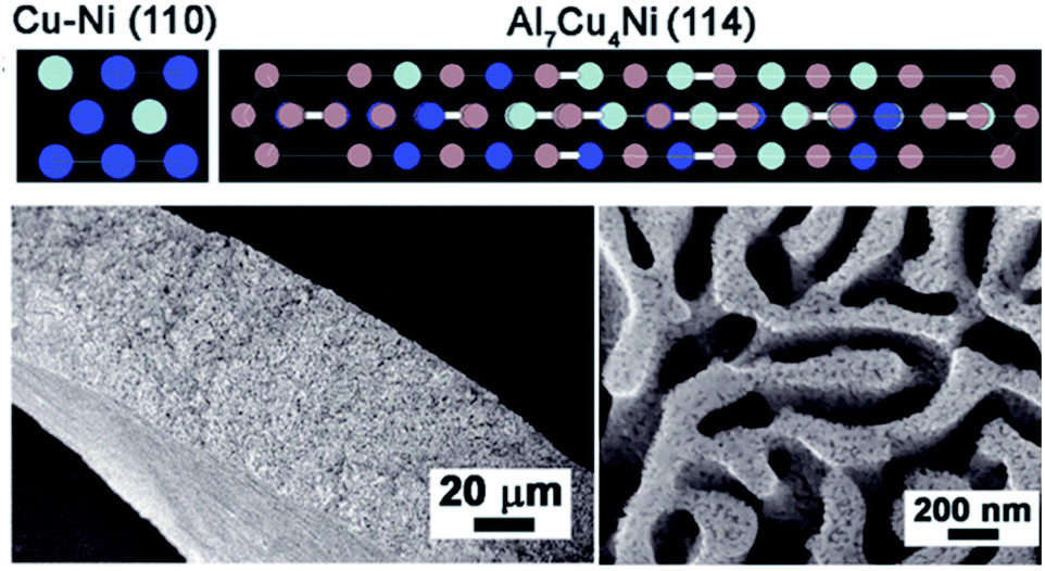 | ||
| Fig. 5 Top: Representative crystalline structure of Cu4Ni alloy and the Al7Cu4Ni intermetallic compound (Cu: blue; Ni: gray; Al: magenta). Bottom left: Cross-sectional SEM picture of Bi-NP Cu12Ni1Al2.6 Bottom right: SEM picture of top-view of Bi-NP Cu12Ni1Al2.6 with bimodal nanoporous structures consisting of micrometer- and nanometer-scale pore channels. Reprinted with permission from ref. 163, copyright 2018, Wiley-VCH. | ||
One of the interesting approaches is high-intensity ultrasound treatment which has recently been used to synthesize the intermetallic AlNi phase. Here, commercially available Al–Ni alloy powder (50 wt% Ni) was dispersed in a water/ethanol mixture and sonicated for 1 h. The acoustic cavitation during the treatment is responsible for the initiation of redox processes on the particle surface leading to changes in its composition. Depending on the water: ethanol composition the different intermetallic Al3Ni2 and Al3Ni phases could be obtained and were successfully investigated for HER catalysis.165,166
Other ingenious methods such as laser ablation or plasma process synthesis have also been utilized to produce PtCo/CoOx167 nanocomposites and FeNi3103 for efficient OER. Lately, the ball milling technique was used to attain Ni50Mo40Ti10 and Ni50Mo50168 for HER and NiFe169 for efficient OER electrocatalysis. Based on the stoichiometry mixing the Fe and Ni at different molar ratios, FeNi3 nitrogen-doped carbon (FeN3/NC) was obtained using a plasma–liquid reaction (Fig. 3c). Plasma engineering improves the electrical properties and surface area and has proven to be a reliable electrocatalyst for OER and ORR.103
Apart from the synthesis, it is also important to thoroughly characterize the intermetallic compounds to understand their geometric and electronic properties so that they can readily be used for electrocatalysis. Usually, powder X-ray and single-crystal X-ray diffraction methods are used to determine their crystallinity, phase identification, and structural analysis with complementary theoretical calculations. Similarly, the surface structural characterization of (amorphous or crystalline) intermetallic compounds are performed by various techniques such as scanning electron microscopy, transmission electron microscopy, selected area electron diffraction, high angle annular dark-field scanning transmission electron microscopy, electron energy-loss spectroscopy, X-ray photoelectron spectroscopy. Besides, the coordination structure of intermetallics is revealed by Raman and X-ray absorption spectroscopy.170
5. Intermetallics for hydrogen evolution
Intermetallic phases have attracted many research groups to investigate their unique properties for water-splitting capability. Especially, intermetallic combinations of transition metals, as composite catalysts for HER, have been the subject of manifold experimental and theoretical studies.171 The pronounced synergism arises from a combination of transition metals with empty or half-filled d-orbitals with metals having more filled orbitals. The latter transition metals have internally paired d-electrons not available for bonding in the pure metal but in combination, giving exceptional charge-transfer capabilities to the formed intermetallic phase. This leads to exceptional electrocatalytic behavior in their intermetallic bi- or a multi-elemental compound that often surpasses precious metals as described by Brewer–Engel valence-bond theory for bonding in metals.172–174According to the concept, various intermetallic combinations of transition metals, such as Hf2Fe, Hf2Co, PtMo, Pt–Mo, ZrPt, Nb–Pd systems, PdTa, and TiPt have been used as electrode material for HER in alkaline media and compared with the conventional transition metal-based materials. In contrast to the conventional cathodes, the intermetallics have shown significant electrocatalytic enhancement with Pt2Mo and Hf2Fe as the most efficient HER catalysts.175,176
5.1 Noble metal-based intermetallics
In electrocatalysis, especially, Pt-based intermetallics have shown high catalytic activity and often outperform non-noble-based alloys.177 Though in water-splitting, many transition metal-based electrodes have demonstrated high electrocatalytic performance in HER, Pt is still considered the highest active catalyst in alkaline and acidic electrolytes.3 With optimal structural properties to adsorb H+ more efficiently, it shows the lowest overpotential and is the most active material in HER.178,179 Therefore, attempts have been made to reduce the proportion of Pt in catalyst materials and design new materials by contemporaneously benefitting from cooperative effects in these composites and boosting electrocatalysis.180 Intermetallic phases of PtDy and PtMo2 with only 50 at% of Pt in their structure showed the highest activity in alkaline HER when compared to their corresponding phases with higher or lower Pt proportion.107,181–183 These observations have also been made for the Ho–Pt and Dy–Pt phases, which were significantly more active than the pure Pt during alkaline HER.184Platinum–germanium NPs were synthesized using the hot injection technique to derive GePt3 and Ge2Pt, both tested for HER activity in 0.5 M H2SO4 electrolyte. While the Ge2Pt phase was found not to be active, GePt3 showed a low overpotential of η–10 = 53 mV and long-term stability during HER catalysis over 12 h. Compared to Pt black and Pt/C, GePt3 displayed higher specific activity corresponding to Pt content and higher mass activity compared to Pt black.124 The group of Tuan synthesized GaPt3 NPs in a similar approach to that of Ge–Pt that acted as highly efficient and stable electrocatalysts for HER. The catalyst was tested in 1 M KOH, phosphate-buffered solution (PBS), and 0.5 M H2SO4 electrolyte resulting in η−10 of 48, 103, and 27 mV, and operated stably under prolonged conditions for over 48 h.122 Another platinum-based intermetallic, Pt3Ti NPs on a two-dimensional transition metal carbide (Pt/Ti3C2Tx) at different temperatures was investigated recently by Li et al. for HER in 0.1 M HClO4 as the electrolyte. The Pt3Ti NPs prepared at 550 °C (Pt/Ti3C2Tx-550) showed the highest activity η−10 of only 32.7 mV.139
In the recent past, Chen et al. compared ordered and disordered phases of PtNi NPs for activity in alkaline HER. The unexpected results showed that the disordered phase was more active than the ordered one. Experimental and theoretical investigations suggested more PtIV and NiII species on the surface of D-PtNi/C as well as a synergetic effect between the formation of Ni/Pt–OH bonds and the increased disordering degree of Pt and Ni atoms on the surface of D-PtNi/C that enhanced the HER in comparison to the ordered species.138 Besides, Krstajic and co-workers synthesized MoPt3via an arc-melting route and investigated the kinetic and physical behavior of the material during acidic HER where they underlined a prominent role of Mo in the catalytic process once the MoPt3 electrode was activated by polishing the surface.185 In addition, a Pt-based silicide was prepared by magnetron-sputtering, giving an electrode of flat morphology containing uniformly spherical NPs with sizes of 10–20 nm. The Pt2Si was tested in 0.5 M H2SO4 electrolyte for HER resulting in η−10 of 78 mV and a Tafel slope of 30.5 mV dec−1.186
Electrode materials containing Pd have also been a focus of research as it is an interesting substitute for Pt. Although Pd is a noble metal, its price is much lower and shows similar activity to Pt in HER.187,188 Replacing the Pt with Pd has shown to be very efficient and phases of intermetallic PdBi2 has proven to be a sufficient replacement in HER catalysis and closely operating at Pt level.119,189 In a direct comparison of Pd-based intermetallic (Pd2Si) often show higher activity than their counterparts with non-noble transition metals (Ni2Si).125
Jana et al. synthesized PdCu3 by chemical reduction in OLA 180 °C and the addition of CTAB to control the reduction rates of Pd and Cu, giving spherical NPs that were highly active towards electrochemical HER. In acidic media (0.5 M H2SO4) high activity of PdCu3 was correlated to the dealloying of Cu from the structure resulting in the formation of active Pd sites with a low coordination number to facilitate the HER.129 Moreover, in a shape-controlled approach, gallium–palladium (GaPd2) nanomaterials were fabricated to drive the electrocatalytic HER. By changing the surfactant during synthesis, GaPd2 polyhedrons, NPs, and nanowires were achieved which were then examined for HER in 0.5 M H2SO4. The GaPd2 NPs exhibited the highest activity with η−10 of 24 mV and a Tafel slope of 57.2 mV dec−1 followed by the polyhedrons (η−10 of 33 mV) and the nanowires (η−10 50 mV). The enhanced activity of the nanowires and stability for 24 h, superior to commercial Pd, was attributed to the increased surface area and the synergetic effect of Pd and Ga within the material.123 Lately, the group of Wu decorated intermetallic Pd3Pb nanoplates with a submonolayer of Pt to enhance acidic HER catalysis. They concluded that the very high activity resulted from the intermetallic substrate that stabilized the atomic structure of the active Pt layer as well as stabilized the electronic structure for effective electron transfer from Pd3Pb to Pt facilitating the electrocatalytic HER.114
Although Pt and Ru-based materials have been considered the best working electrocatalysts for HER, very recently, Ir has also garnered significant attention towards HER.190,191 As Ir can provide better stability at a high anodic potential than Ru in acidic conditions, it is considered as one of the very few catalysts driving efficient OER and HER in a broad range of pH.191 Making use of the bifunctionality with an oxophilic metal to promote the water dissociation and production of hydrogen intermediates, a structurally ordered intermetallic Ir3V was synthesized by Chen and co-workers to facilitate the HER. Vanadium being a highly oxophilic metal with the strongest metal–OH bond among the transition metals formed a structurally ordered phase with Ir (Ir3V) resulting in superior electrocatalytic behavior for alkaline HER. The achieved η−10 was only 9.0 mV even under prolonged conditions and revealed a Tafel slope of 24.1 mV dec−1 and clearly outmatching Pt/C and Ir/C references.137
5.2 Non-noble metal-based intermetallics
Completely replacing noble metals as catalyst materials remains a challenge in HER, especially since pure Mo, Fe, Co, or Ni bind H+ too weakly or too strong and therefore, are more or less inactive in HER.192 But when these metals were alloyed, a positive effect on the HER activity was observed with improved H+ adsorption characteristics and reduced overpotentials.193 Demonstrating exceptional physical and chemical properties, non-noble intermetallics have attracted many research groups to profoundly study this new class of materials for application in HER.194In this respect, Rosalbinao et al. revealed that the electrocatalytic properties of Fe could be increased by forming intermetallic phases of Fe with rare earth metals. By the appropriate combination of 3d6-orbitals of Fe with 5d1-orbitals of Ce or La, according to the Brewer–Engel valence-bond theory, the HER performance of the final material was significantly enhanced to industrial standard. In their series, they found that the Fe–MM (MM = mixed metal) alloy, primary (Fe) crystals surrounded by a Fe17R2 phase (R content is Ce 5.5, Pr 1.5, Nd 1.5, Sm 0.5, Eu 0.2, Gd 0.3, Tb 0.5 and Dy 0.5 in at%) noted as Fe90MM10 and Fe90Ce10 to be most active for the alkaline HER.89 Furthermore, the positive effect of Ce in the structure was also observed in Ni–Zn-coatings containing the intermetallic NiZn3, Ni2Zn11, and NiZn7.33 phases. The composite material embedded with CeO2 NPs increasing HER activity than the one without the inclusion of CeO2.156
In order to surpass the performance of Raney nickel electrodes, Ti2Ni and TiNi were synthesized which showed considerably good performances in HER with small activation energies to mediate the reaction and extend higher stability than the Raney nickel references.87,195,196 Intense studies on the Ti–Ni system revealed a decreasing trend for HER activity in the order TiNi2 > TiNi3 > TiNi4 > Ti2Ni > TiNi > Ti3Ni > TiNi0.7 in which only TiNi3 exhibited the highest activity.197 The Raney nickel system with Ni3Al as analogous to TiAl with a similar face-centered cubic unit cell as well as structural order has also been investigated as the catalyst material for HER.198 Early reported phase pure Ni2Al3 and NiAl3 with minor impurities of Ni2Al3 were tested in 1 M KOH for HER activity and demonstrated good activity and stability. The porosity of the electrode material could be increased with Al content and the addition of Mo in the alloyed material could even further increase the HER activity.92 Comparable observations were made when the intermetallic phases of TiAl, FeAl, and NiAl were additionally alloyed with 2 at% of transition metals M = Ti, V, Cr, Mn, Fe, Co, Ni, and Cu. Additional alloying in general influenced activity, but, the more electron-rich the alloying metal became, the stronger the influence was on the overpotential and the HER activity.199 Similarly prepared Ni3Al by Wu et al. and Dong et al. through elemental powder reaction revealed enhanced porosity of the electrode materials and activity for alkaline HER. They observed that the intermetallic phase showed increased corrosion resistance and acquired a higher surface area due to the porous structure, as well as lower charge transfer resistance enhancing the HER compared to the pure Ni phase.93,94 Besides, Ni-based intermetallic phases combined with rare earth elements such as La or Mm (Mm = mixed metal) also displayed promotional effects on HER activity. Tamura's group studied LaNi5- and MmNi5-type alloys as electrode materials for HER and found that it shows Pt/Pd-like behavior and activity.200–202 Recently, a Ni–Co–Al lamellar nanostructure was attained by arc melting technique and tested for HER in a 1 M KOH electrolyte. Additional aging of Ni–Co–Al in an oven and etching in alkaline media, the material was dealloyed resulting in a higher ECSA resulting in a higher HER activity with η−10 of 178 mV when compared to a Ni foil standard.111 In a very different approach, Sun et al. synthesized Al7Cu4Ni@Cu4Ni core/shell nanocrystals by a melting-spinning method for highly efficient HER in alkaline media. The hybrid material showed η−10 of 139 mV and a Tafel slope of 110 mV dec−1 mediating the HER over a prolonged time of 8 h with a minimal shift of ∼14 mV. The high activity was accounted to the Ni incorporation that leads to a bimodal nanoporous architecture that simultaneously facilitates electrolyte access and electron transport as well as adapts the binding energy for H+ in nearby Cu atoms.163
Mo-based intermetallics are considered as a suitable substitute for electrode materials in HER since their activity often proved to be much higher with more favorable kinetics than pure Mo or Ni-based electrodes.91,203–205 McKone et al. directly compared the HER activity of Ni and Ni–Mo nanopowders revealing enhanced per-surface-atom activity compared to the bare Ni.206 Meanwhile, the group Jaramillo investigated intermetallic phases of NiMo, NiMoCo, CoMo, and NiMoFe for HER in acidic conditions and found a much higher activity than for Pt deposited on rotating disc electrodes.207 MoNi4 supported by MoO2 cuboids grown on NF via hydrothermal synthesis and annealing in the H2 atmosphere have shown remarkable activity towards HER, favoring the largely reduced Volmer step. With η−10 of 15 mV and a Tafel slope of 30 mV dec−1, this catalyst is considered as the best Pt-free HER catalyst in alkaline media.208 A study on ordered Mo7Ni7, disordered Ni0.92Mo0.08, and pure Ni powders for HER activity was also conducted that revealed the highest activity for the disordered species. Due to the high surface area, the disordered Ni0.92Mo0.08 favored the catalytic process, but when mass-specific activity was normalized to the surface area (determined by BET) rather than interfacial capacitance, the ordered Mo7Ni7 showed more intrinsically activity.143 A positive influence of Ti on the electrochemical performance in intermetallic NiMo was observed by Panek and co-workers. Ni50Mo40Ti10 demonstrated high intrinsic activity and much lower overpotentials for HER than the identically prepared Ni50Mo50.168 Enhancement of HER activity in Ni–Mo electrocatalysts was also achieved by including carbon nanostructures into the catalytic process. By caging Ni4Mo NPs into N-doped graphite tubes, a significant amplification of HER activity was observed with an η−10 as low as 65 mV a Tafel slope of 67 mV dec−1 to mediate acidic HER for 15 h.104 Additionally, the catalytic HER activity was improved by covering the surface of a porous NiMo network with N-doped graphene also strengthened the chemical stability of the system.130
Intermetallic stannides are known to possess unique chemical bonding with high electrical conductivity.86 The earlier work on nickel stannides, Ni3Sn and Ni3Sn2, fabricated via solid-state proved to be more active than their homometallic counterparts.88,209 Likewise, inspired by the previous works, Krstajic and his group electrodeposited Ni–Zn coatings and applied for alkaline HER and acquired promising results. The electrodes contained a mixture of different intermetallic phases (Ni, Ni3Sn, Ni(1+x)Sn(0<x>0.5), Ni3Sn4) with varying chemical composition, phase composition, and morphology, and the effect of morphology on the activity was the most pronounced.157
Most recently, Suen and co-workers systematically synthesized a series of intermetallics, MCo2 (M = Ti, Zr, Hf, and Sc) using a rapid arc-melting method and studied their effects on HER. In this series, TiCo2 displayed a promising activity with an η−10 of 70 mV, a Tafel slope of 33 mV dec−1, and stability of 12 h and, this activity was comparable to a Pt/C standard.109
Efforts to stabilize and fine-tune the electronic structure by chemical synergism and structural site-isolation have been made to fabricate highly active non-noble catalysts. Based on the concept, FeCoNiAlTi, a high-entropy intermetallic (HEI) possessing the unusual periodically ordered structure was synthesized.162 The partially dealloyed HEI by acid etching showed high alkaline HER activity with an η−10 of 88.2 mV, a Tafel slope of 40.1 mV dec−1, and stability of 40 h (Fig. 6a–c).162 Here, the lowering of the overpotential was ascribed to the chemical complexity and unique atomic configurations that deliver a strong synergistic function to alter the electronic structure by optimizing the required energy barrier for hydrogen evolution.
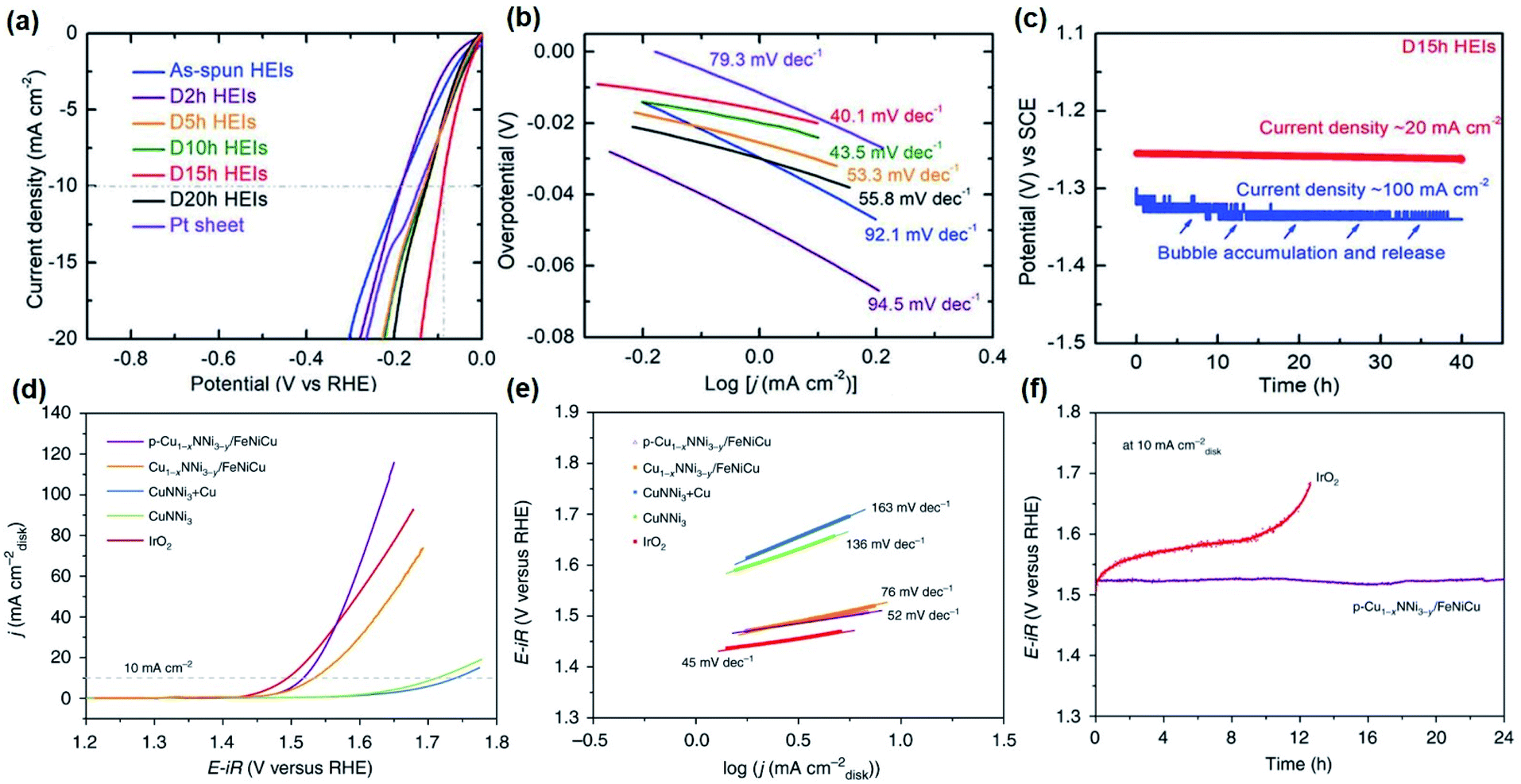 | ||
| Fig. 6 Electrocatalytic performance for HER and OER of selected catalysts: (a) HER LSV curves and (b) Tafel plots at a scan rate of 5 mV s−1 with iR loss correction of FeCoNiAlTi HEI and references in 1 M KOH. (c) Long-term stability measurement of the FeCoNiAlTi HEI at a current density of 20 and 100 mA cm−2 without iR loss correction. Figures (a–c) are reprinted with permission from ref. 162, copyright 2020, Wiley-VCH (d) OER LSV curves of Cu1−xNNi3−y/FeNiCu and references in 1M KOH at 5mVs−1. (e) Tafel slopes of Cu1−xNNi3−y/FeNiCu and references obtained from the steady-state measurements. (e) CP measurements of p-Cu1−xNNi3−y/FeNiCu and commercial IrO2 at 10mAcm−2. Figures (d–f) are reprinted with permission from ref. 99, copyright 2020, Nature Publishing Group. | ||
Apart from conventional intermetallic compounds, sulfur-based intermetallic Al25Co7S64 was also prepared by dealloying Al90Co10 in 6 M KOH followed by solid-vapor sulfurization was highly active for HER in acidic electrolyte. The Al–CoS2 showed η−10 of 70 mV a Tafel slope of 153.5 mV dec−1 and was found to be stable for 12 h.96 An up-to-date table on the activity parameters of intermetallics has been provided in Table 1.
| Catalyst (substrate) | Electrolyte | Current density (mA cm−2) | Overpotential (mV) | Tafel slope (mV dec−1) | Reference |
|---|---|---|---|---|---|
| a FTO = fluorine doped tin oxide, GC = glassy carbon, NF = nickel foam. | |||||
| Al7Cu4Ni@Cu4Ni (direct) | 0.1 M KOH | −10 | 139 | 110 | 163 |
| CoSn2 (NF) | 1 M KOH | −10 | 103 | — | 221 |
| CoSn2 (FTO) | 1 M KOH | −10 | 196 | 78 | 221 |
| np-AlNiCoIrMo HEA (GC) | 0.5 M H2SO4 | −10 | 18.5 | 33.2 | 100 |
| NiIrRuAl-3/1 (GC) | 0.1 M HClO4 | −10 | 14 | 23 | 164 |
| D-PtNi/C (GC) | 1 M KOH | −10 | 40 | 55 | 138 |
| FeCoNiAlTi HEI (direct) | 1 M KOH | −10 | 88.2 | 40.1 | 162 |
| Fe90Y10 (direct) | 1 M KOH | −250 | 470 | 125 | 89 |
| Fe90MM10 (direct) | 1 M KOH | −250 | 350 | 85 | 89 |
| Ni–Zn (steel) | 1 M NaOH | 2.47 | 0 | 119 | 156 |
| AlNiHT30 + L (Ni) | 1 M KOH | −100 | 123 | 76 | 160 |
| Ni3Al (direct) | 6 M KOH | −90.1 | 426 | 219 | 93 |
| Ni2Al3 @ 25 °C (Cu) | 1 M KOH | −250 | 280 | 200 | 92 |
| Ni2Al5 @ 25 °C (Cu) | 1 M KOH | −250 | 253 | 157 | 92 |
| NiAl3 @ 25 °C (Cu) | 1 M KOH | −250 | 136 | 99 | 92 |
| NiAl3Mo0.153 @ 25 °C (Cu) | 1 M KOH | −250 | 57 | 134 | 92 |
| NiAl3Mo0.262 @ 25 °C (Cu) | 1 M KOH | −250 | 60 | 99 | 92 |
| Ni–Co–Al (direct) | 1 M KOH | −10 | 178 | 158 | 111 |
| Ni–LaNi5 (Cu) | 1 M NaOH | −250 | 330 | 101 | 222 |
| Ni–MmNi3.4Co0.8Al0.8 (Cu) | 1 M NaOH | −250 | 351 | 113 | 222 |
| Mo7Ni7 (Ti) | 1 M KOH | −3.7 (BET) | 200 | — | 143 |
| Ni0.92Mo0.08 (Ti) | 1 M KOH | −1 (BET) | 200 | — | 143 |
| MoNi4 (Ni) | 1 M KOH | −10 | 15 | 30 | 208 |
| Porous MoNi4 networks (Ni) | 1 M KOH | −10 | 28 | 36 | 131 |
| Co3Mo (direct) | 1 M KOH | −10 | 12 | 40 | 113 |
| TiCo2 (direct) | 1 M KOH | −10 | 70 | 33 | 109 |
| HfCo2 (direct) | 1 M KOH | −10 | 87 | 47 | 109 |
| ScCo2 (direct) | 1 M KOH | −10 | 87 | 36 | 109 |
| GePt3 (FTO) | 0.5 M H2SO4 | −10 | 53 | 37 | 124 |
| PdCu3 (GC) | 0.5 M H2SO4 | −10 | 50 | 34 | 129 |
| Pt2Si (Ti) | 0.5 M H2SO4 | −40 | 78 | 30.5 | 186 |
| Pt–Dy (direct) | 8 M KOH (@25 °C) | −100 | 409 | 147 | 107 |
| Pt–Dy (direct) | 8 M KOH (@85 °C) | −100 | 139 | 141 | 107 |
| GaPt3 (GC) | 0.5 M H2SO4 | −10 | 27 | 43.3 | 122 |
| GaPt3 (GC) | 1 M KOH | −10 | 48 | 63.1 | 122 |
| GaPt3 (GC) | PBS | −10 | 103 | 85.3 | 122 |
| PdBi2 (GC) | 0.5 M HClO4 | −10 | 78 | 63 | 119 |
| GaPd2 nanowires (GC) | 0.5 M H2SO4 | −10 | 50 | 57.2 | 123 |
| Pd2Si (Ti) | 0.5 M H2SO4 | 192 | 192 | 131 | 125 |
| Ni2Si (Ti) | 0.5 M H2SO4 | 243 | 243 | 66 | 125 |
| Ir3V (GC) | 1 M KOH | −10 | 9.0 | 24.1 | 137 |
| np-Co(Al) (direct) | 0.5 M H2SO4 | −10 | 239 | 153.50 | 96 |
| Pt3Ti (carbon fiber) | 0.1 M HClO4 | −10 | 32.7 | 32.3 | 139 |
| AL-Pt/Pd3Pb (GC) | 0.5 M H2SO4 | −10 | 14 | 18 | 114 |
| NiMo-(a) (GC) | 1 M H2SO4 | −10 | 39 | — | 207 |
| NiMo-(a) (GC) | 1 M KOH | −10 | 30 | — | 207 |
| Porous NiMo (GC) | 0.5 M H2SO4 | −10 | 22 | 37 | 130 |
| NiMo-NHG (GC) | 0.5 M H2SO4 | −10 | 30 | 41 | 130 |
| NiMo (1 mg cm−2) (Ti) | 2 M KOH | −20 | 70 | — | 206 |
| NiMo (3 mg cm−2) (Ti) | 0.5 M H2SO4 | −20 | 80 | — | 206 |
| NiMo-NGTs (GC) | 0.5 M H2SO4 | −10 | 65 | 67 | 104 |
| Ni50Mo40Ti10 (573 K) (direct) | 5 M KOH | −100 | 215 | 249 | 168 |
| Ni50Mo50 (573 K) (direct) | 5 M KOH | −100 | 245 | 240 | 168 |
Although Pt and Pt-based alloys remain as the most active materials for HER with η−10 between 10–20 mV and Tafel slopes ranging from 25–30 mV dec−1,210 recently, several non-noble metal catalyst based have attracted tremendous attention. Especially, Mo-based catalysts such as CoMoS2 with η10 = 56 mV and a Tafel slope = 32 mV dec−1 or Co–MoC with η10 = 46 mV and a Tafel slope = 46 mV dec−1 running stable for over 500 h, are considered potential candidates to replace Pt in electrochemical HER.211,212 In comparison, judging from the HER activities, the intermetallic-based catalysts have added advantages (see Section 8) and are on par with the other benchmarking systems, thus, are the most suitable candidates for HER catalysis.213
6. Intermetallics for oxygen evolution reaction
6.1 Noble metal-based intermetallics
Traditionally, RuOx and IrOx are still considered as the best working electrode materials for OER but their low abundance and high cost have limited their broad industrial application.214,215 However, the extraordinary stability especially in acidic media still makes these elements the first choice as anodes. Ruthenium catalysts usually are slightly more active and iridium-based catalysts are considered more stable for OER. Taking this into account, intermetallic catalysts based on Ru and Ir have been investigated both in acidic and neutral OER. Xu et al. reported IrRu@Te accessed via a solvothermal approach that exhibited low η10 of 220 (Tafel slope = 35 mV dec−1), 245, and 309 mV in 0.5 M H2SO4, 0.05 M H2SO4, and neutral electrolytes maintaining continuous OER catalysis in strong acid (0.5 M H2SO4) for 20 h at 10 mA cm−2 with a minimal decline in activity.132Besides Ru and Ir, nanostructured Pt or prevailing intermetallic phases such as MoPt3–HfPd3 composite materials are proposed to provide substantially advanced electrocatalytic properties for OER.216 To develop corrosion-resistant catalysts for OER, Pt-based catalysts are the optimal alternative to realize highly active and long-term stable electrocatalysis. PtCo NPs embedded into CoOx matrices showed remarkable resistance against aggregation and dissolution in alkaline media.167 The observed η10 of 380 mV (Tafel slope = 71.2 mV dec−1) for OER was far lower compared to Co-oxide and Pt/C with appreciated long-term stability.167 In a novel approach to assemble intermetallics, Lee and co-workers uncovered rhombic dodecahedral IrNi and PtNi nanoframes. Within them, IrNi exhibited surprisingly high activity towards OER catalysis with η10 = 325.8 mV a Tafel slope of 48.6 mV dec−1 and was structurally stable for 5000 cycles outperforming the Ir/C reference catalyst with a low Tafel slope of 48.6 mV dec−1. The enhancement in the activity of IrNi was ascribed to the unique structural and chemical composition of the material.120 Recently, Antonyshyn et al. synthesized the intermetallic Al2Pt phase for efficient OER giving rise to a moderate η10 of 450 mV that was better than the Pt reference. In addition to the activity, it showed a stable performance after activation during the first 100 h for more than 450 h.108
6.2 Non-noble metal-based intermetallics
In the last few years, numerous oxide-based materials have been investigated to address the concerns of the activity and stability of electrocatalysts during OER. Nevertheless, the lack of good electrical conductivity to enable an efficient charge transfer process constrains their widespread use. In this respect, transition metal-based intermetallics have been regarded as the most suitable electrocatalysts for OER as they comprise both desired chemical and physical properties. As intermetallics can also be cost-effectively prepared on a large scale, they have now gained enormous attention in the field of water-splitting catalysts.217 The group of Schuhmann recently investigated several intermetallics such as NiAs (η10 = 360 mV, Tafel slope = 58.7 mV dec−1) and Ni2Si (η10 = 410 mV, Tafel slope = 70.9 mV dec−1) for noble metal-free OER in alkaline electrolytes. They observed enhanced intrinsic OER activity in several metalloids resulting from unique electronic and structural properties in certain composite materials.218 Around the same time, Proost and co-workers studied a series of Ni–Al compounds for efficient water oxidation. They synthesized a series of pure Ni, AlNi3, AlNi, and a composite of AlNi3 and Al3Ni5 as electrode material on a Si substrate and compared their activity towards OER. Out of all, AlNi3 exhibited the highest activity with an η10 of 300 mV operating stably at this current density under prolonged conditions for 4 h and a Tafel slope of 103 mV dec−1.219 Additionally, annealing of as prepared Ni3Al at different temperatures to study the coarsening effect on HER activated the electrocatalyst. The most stable and active species was received by annealing deposited Ni3Al at 1160 °C.95 On the other hand, advanced stability, and high intrinsic activity were achieved by Yang's group using a eutectic high entropy alloy (EHEA) as a template to synthesize the multicomponent porous structure (MCPS) FeCoNiCrNb0.5 for OER catalysis. Their composite material showed excellent performance reaching 288 mV at η10 with a Tafel slope of 27.67 mV dec−1 and durability for 30 h.101Of late, earth-abundant and considerably acid-stable tantalum-based intermetallics have also been considered as promising candidates for OER in acidic media. Schaak and co-workers reported a bimetallic series of Ta with Co, Ni, and Fe were produced by arc melting from the elemental metal powders in the stoichiometric composition. The obtained intermetallic Ni2Ta, Fe2Ta, and Co2Ta phases were pressed into pellets and used as electrodes for OER catalysis with Ni2Ta showing the highest activity at an η10 of 570 mV with the stability of over 60 h.110
Transition metal silicides have gained much attention lately for their specific crystal and electronic structures with high conductivity and stability that are the decisive factors for catalytic water-splitting.220 For application in anion exchange membrane fuel cells, bifunctional cobalt and nickel silicide have been decorated on silicon-oxy-carbide (SiOC) and tested for OER and oxygen reduction reaction (ORR). The synthesized Co/SiOC contained Co2Si and traces of pure Co while the Ni/SiOC consisted of a mixture of Ni2Si and Ni3Si. From both species, Ni/SiOC showed the highest performance in OER with η10 of 390 mV and exhibited better OER kinetics during catalysis.223 Following this, Kumar et al. used the molten LiI–KI eutectic mixture to access NiSi and Ni2Si via a reactive ionic Zintl solid (Na4Si4) and a Ni precursor. To reach a current density of 10 mA cm−2 an η of 570 mV was needed for NiSi and Ni2Si, which was comparable to a commercial IrO2 reference.224 In addition, porous Fe3Si, Fe5Si3, and FeSi have been prepared as intermetallic anode for zinc electrowinning. While the Fe3Si showed the best OER performance with η10 = 955 mV and a Tafel slope of 253 mV dec−1, the Fe5Si3 (η10 = 1072 mV, Tafel slope = 327 mV dec−1) exhibited better stability over 400 h.90
FeNi3 NPs on NC were synthesized by Mu and co-workers and the resulting FeNi3@NC electrocatalyst displayed excellent OER activity of η10 = 277 mV (Tafel slope = 77 mV dec−1) in alkaline conditions which they attribute to the unique structure with improved physical properties.225 To understand such systems more in-depth, Chen et al. studied a series of Fe–Ni intermetallics on NC gaining deeper insight into the role of iron in the structure. They synthesized various FeNi3/NC, Fe–FeNi3/NC, and Fe-enriched FeNi3/NC electrocatalysts and found the Fe-enriched FeNi3/NC was most active for OER with η10 of 360 mV and a Tafel slope of 82 mV dec−1 followed by Fe–FeNi3/NC (η10 = 390 mV, Tafel slope = 86 mV dec−1) and FeNi3/NC (η10 = 450 mV, Tafel slope = 141 mV dec−1) to reach the same current density concluding the higher Fe incorporation led to a positive effect giving more disorder to the structure.103 The influence of Fe in the Ni3Al structure was also investigated by Bai et al., where the highest activity for OER was observed Ni2/3Fe1/3Al with an η10 of 299 mV and a Tafel slope of 58.9 mV dec−1, which was much lower compared to Ni3/4Fe2/4Al, Ni1/2Fe1/1Al, and other alloy materials.169
Das and co-workers prepared ultra-small intermetallic NiZn phase using Ni NPs with organometallic Zn precursor using low-temperature solution chemistry. This non-precious electrocatalyst showed a substantial OER in alkaline solution with an estimated η10 of 283 mV, a Tafel slope of 73 mV dec−1, and stability of 16 h and surpassed the activity of pure Ni and Ni0.7Zn0.3 alloy.226 Similar observations were drawn also in a comparative study on NiSn coatings on electrodes used for alkaline OER. The electrodeposited NiSn films at different potentials showed higher intrinsic activity than bare Ni films and the most active intermetallic phase NiSn100 reached η40 at 473 mV and a Tafel slope of 64 mV dec−1.227
Antiperovskite materials are intermetallic compounds with a perovskite crystal structure but instead, the anion and cation positions are interchanged in the unit cell.228 Transition metals and nitrogen or carbon can form antiperovskite structures at suitable compositions (AXM3; A = Cu, Al, Zn, etc.; X = N or C; M = Ni, Fe, Co, etc.), and can be well engineered to demonstrate versatile properties for OER catalysis.99 The p-Cu1−xNNi3−y/FeNiCu from Shao's group exhibited superior OER activity (η10 of 260 mV and Tafel slope of 52 mV dec−1) in alkaline media with at long-term stability over 24 h exceeding the activity of IrO2 (Fig. 6d–f).99 Inspired by this, Zou et al. developed a new intermetallic antiperovskite Co3InC0.7N0.3 that showed impressive OER activity with η10 of 260 mV, Tafel slope of 76.2 mV dec−1 and moderate stability of 10 h, and presented valuable insights into the active structure of this unique material class.229
We investigated a manganese gallide (MnGa4) and iron germanide (Fe6Ge5), both prepared by solid-state synthesis for potential application in alkaline OER. The MnGa4 is a d-sp bonded Hume–Rothery intermetallic compound with strong directional (covalent) bonds, metallic behavior, and antiferromagnetic ordering.78,230 The prepared MnGa4 has a defective CsCl structure, where three-fourths of the Cs atoms are eliminated to form corner-linked cubes (MnGa8/2) and proved to be a magnificent precatalyst for the electrochemical OER with a η10 of 293 mV (Tafel slope = 98 mV dec−1) for more than 24 h.97 Alternatively, Fe6Ge5 crystal structure consisted of a dense packaging of Fe and Ge atoms, built up by polyhedral of five different Fe atoms forming square pyramids, distorted octahedral and pentagonal prisms with the Ge atoms. In comparison to pure Fe-based materials, the Fe6Ge5 showed superior OER activity with η10 of 221 mV and a Tafel slope of 32 mV dec−1 and was constantly mediated the reaction under high potential for more than a day. In continuation, we further developed synthetic strategies to obtain NiGe105 and FeAs149 from molecular SSPs. The nanoparticular intermetallic phases proved to be very efficient during alkaline OER exhibiting low overpotentials and prolonged stability of three weeks.105 A chemical reduction approach was also utilized to derived phase pure FeSn2 nanocrystals recorded one of the lowest η10 of 197 mV (Tafel slope = 33 mV dec−1) with the stability of over 60 h. This system was found to be even superior to analogous Fe-, FeNi as well as noble-metal-based materials.102 An up-to-date table on the activity parameters of intermetallics has been provided in Table 2.
| Catalyst (substrate) | Electrolyte | Current density (mA cm−2) | Overpotential (mV) | Tafel slope (mV dec−1) | Reference |
|---|---|---|---|---|---|
| a FTO = fluorine doped tin oxide, GC = glassy carbon, NF = nickel foam. | |||||
| FeAs (NF) | 1 M KOH | 10 | 252 | 32 | 149 |
| FeSn2 (NF) | 1 M KOH | 10 | 197 | 33 | 102 |
| CoSn2 (NF) | 1 M KOH | 10 | 230 | — | 221 |
| CoSn2 (FTO) | 1 M KOH | 10 | 299 | 89 | 221 |
| np-AlNiCoIrMo HEA (GC) | 0.5 M H2SO4 | 10 | 233 | 55.2 | 100 |
| NiIrRuAl-1/3 (GC) | 0.1 M HClO4 | 10 | 237 | 50 | 164 |
| Fe6Ge5 (FTO) | 1 M KOH | 10 | 322 | — | 98 |
| Fe6Ge5 (NF) | 1 M KOH | 10 | 228 | 56 | 98 |
| NiGe (FTO) | 1 M KOH | 10 | 322 | — | 105 |
| NiGe (NF) | 1 M KOH | 10 | 228 | 56 | 105 |
| Porous MoNi4 networks (Ni) | 1 M KOH | 10 | 280 | 79 | 131 |
| Co3Mo (direct) | 1 M KOH | 164 | 350 | 82 | 113 |
| FeNi3@NC (GC) | 1 M KOH | 10 | 277 | 77 | 225 |
| FeNi3/NC (GC) | 0.1 M KOH | 10 | 450 | 141 | 103 |
| Fe-enriched FeNi3/NC (GC) | 0.1 M KOH | 10 | 360 | 82 | 103 |
| MnGa4 (NF) | 1 M KOH | 10 | 293 | 98 | 97 |
| Co/SiOC (GC) | 0.1 M KOH | 10 | 440 | 118 | 223 |
| Ni/SiOC (GC) | 0.1 M KOH | 10 | 390 | 90 | 223 |
| NiSi (GC) | 0.1 M KOH | 10 | 570 | 119 | 224 |
| Ni2Si (GC) | 0.1 M KOH | 10 | 570 | 94 | 224 |
| Ni2Ta (direct) | 0.5 M H2SO4 | 10 | 570 | — | 110 |
| Co2Ta (direct) | 0.5 M H2SO4 | 10 | 600 | — | 110 |
| Fe2Ta (direct) | 0.5 M H2SO4 | 10 | 770 | — | 110 |
| IrNi-RF (GC) | 0.1 M HClO4 | 10 | 313.6 | 48.6 | 120 |
| FeSi (direct) | 1.6 M H2SO4 | 10 | 1107 | 634 | 90 |
| Fe5Si3 (direct) | 1.6 M H2SO4 | 10 | 1072 | 327 | 90 |
| Fe3Si (direct) | 1.6 M H2SO4 | 10 | 955 | 253 | 90 |
| PtCo-1 (GC) | 1 M KOH | 10 | 380 | 71.2 | 167 |
| PtCo-3 (GC) | 1 M KOH | 10 | 386 | 65.9 | 167 |
| IrRu@Te (GC) | 0.5 M H2SO4 | 10 | 220 | 35 | 132 |
| IrRu@Te (GC) | 0.05 M H2SO4 | 10 | 245 | — | 132 |
| IrRu@Te (GC) | PBS | 10 | 309 | — | 132 |
| Al2Pt (direct) | 0.1M HClO4 |
10 | 450 | — | 108 |
| AlNi3 (Si) | 1 M KOH | 10 | 300 | 46 | 219 |
| AlNi3/Al3Ni5 (Si) | 1 M KOH | 10 | 390 | 52 | 219 |
| AlNi (Si) | 1 M KOH | 10 | 310 | 47 | 219 |
| Ni3Al N-0 (direct) | 1 M KOH | 10 | 320 | 112 | 95 |
| Ni3Al N-1160 (direct) | 1 M KOH | 10 | 280 | 73 | 95 |
| Ni3Al N-1200 (direct) | 1 M KOH | 10 | 293 | 85 | 95 |
| Ni3Al N-1240 (direct) | 1 M KOH | 10 | 300 | 103 | 95 |
| Ni3Al N-1280 (direct) | 1 M KOH | 10 | 305 | 108 | 95 |
| Ni2/3Fe1/3Al (direct) | 1 M KOH | 10 | 299 | 58.9 | 169 |
| Co3InC0.7N0.3 (GC) | 1 M KOH | 10 | 350 | 76 | 229 |
| CuNNi3+Cu (GC) | 1 M KOH | 10 | 510 | 163 | 99 |
| CuNNi3 (GC) | 1 M KOH | 10 | 480 | 136 | 99 |
| Cu1−xNNi3−y/FeNiCu (GC) | 1 M KOH | 10 | 300 | 76 | 99 |
| p-Cu1−xNNi3−y/FeNiCu (GC) | 1 M KOH | 10 | 280 | 52 | 99 |
| NiZn (GC) | 1 M KOH | 10 | 283 | 73 | 226 |
| CusSn@Cu (Cu) | 1 M KOH | 50 | 384 | 177 | 232 |
| NiSn10 (Ni) | 1 M NaOH | 40 | 541 | 60 | 227 |
| NiSn60 (Ni) | 1 M NaOH | 40 | 516 | 63 | 227 |
| NiSn100 (Ni) | 1 M NaOH | 40 | 473 | 57 | 227 |
| FeCoNiCrNb0.5 (direct) | 0.1 M KOH | 10 | 288 | 27.67 | 101 |
| AlNiHT10 + L (Ni) | 1 M KOH | 100 | 338 | — | 160 |
The most active non-noble benchmarking systems for OER are based on metal oxides, (oxy)hydroxides, and chalcogenides. For instance, the η10 of several present NiFe or NiCo (oxy)hydroxides and oxide systems range only between 180 to 240 mV with Tafel slopes of 28–35 mV dec−1 that also remain stable for several hours even at higher current densities of 500 mA cm−2 and 1000 mA cm−2.33 Similarly, most of the other active materials such as perovskites, phosphides, alloys and carbides displaying overpotentials between 200–300 mV with Tafel slopes ranging from 40–80 mV dec−1 to facilitate OER have lately been reported. Interestingly, the OER activities of these materials are matched closely with recently reported intermetallic phases and likely to improve significantly based on the structural tuning, composition, and electronic conductivity (see Section 8) making them an intriguing class of materials for further investigations.231
7. Intermetallics for overall water-splitting
Electrocatalytic overall water-splitting with intermetallic phases is a relatively nascent field with only a few reported examples.29,30 An early study on several alloys and intermetallics, e.g. Ti2Ni, TiNi, TiCu, TiCo, and ZrNi from Miles revealed that proper combinations of elements can be favorably modified to facilitate HER and OER.Although no further investigations on structure, morphology, or physical properties were carried out, a correlation on periodic trends of overpotential and atomic number with modern values for electronic work functions was derived for water splitting.87 To increase the roughness factor, Møller's group fabricated AlNi electrodes for alkaline water electrolysis and highlighted the importance of large ESCA and low charge transfer resistance for efficient water splitting, although, the electrodes deteriorated dramatically during the harsh reaction conditions.160 Taking inspiration from the previous works, we carefully designed and developed a novel strategy for a controllable synthesis CoSn2 nanocrystals that contained both active and conducting sites.221 As anticipated, CoSn2 displayed an excellent η10 of 230 mV for OER, η−10 of 103 mV, and necessitated a cell potential of 1.55 V to reach 10 mA cm−2 in alkaline solution with almost 100% FE surpassing their Co and Sn counterparts.
In search of new overall water splitting electrocatalysts, Zhang and co-workers synthesized a noble metal-based intermetallic NiIrRuAl-1/3 with low content of Ir and Ru (34 at%) to form a hierarchically nanoporous nanowire structure with high ECSA that showed η10 of 237 mV (Tafel slope = 50 mV dec−1) for OER, while the NiIrRuAl-3/1 performed best in HER with η−10 of 14 mV (Tafel slope = 23 mV dec−1) and a cell potential of 1.464 V was required for NiIrRuAl-1/3//NiIrRuAl-3/1 in an acidic media with extended stability of 35 h outperforming IrO2 and Pt/C references.164 At the same time, a three-dimensional porous intermetallic MoNi4 network was constructed by Jin et al. that demonstrated impressive performance as electrode material displaying η−10 of the only 28 mV (Tafel slope = 36 mV dec−1) for HER, η10 of 280 mV (Tafel slope = 79 mV dec−1) for OER. When examined for bifunctional overall water splitting, a cell potential of 1.58 V at a current density of 10 mA cm−2 was observed with over 24 h stability, which was significantly better than the reference Ni electrodes.131 Soon after, an Al3(NiCoIrMo) intermetallic phase was accessed via solid-state route and partial dealloying to a reduced content of Ir in the structure (∼20 at%). The quinary nanoporous np-AlNiCoIrMo HEA needed η−10 of 18.5 mV (Tafel slope = 33.2 mV dec−1) for HER, η10 of 233 mV (Tafel slope = 55.2 mV dec−1) for OER, and overall cell voltage of 1.505 V with high durability of 48 h.100 Moreover, Shi and co-workers developed self-supported monolithic nanoporous Co3Mo/Cu electrodes from Cu12−x−yCoxMoyAl88 precursors, which showed unexpected performance for HER with η−10 of merely 12 mV (Tafel slope = 40 mV dec−1) while η164 for OER was 350 mV (Tafel slope = 82 mV dec−1) (Fig. 7).113 The catalyst was further tested for overall water-splitting resulting in a cell potential of 1.65 V to produce a current density of 100 mA cm−2.
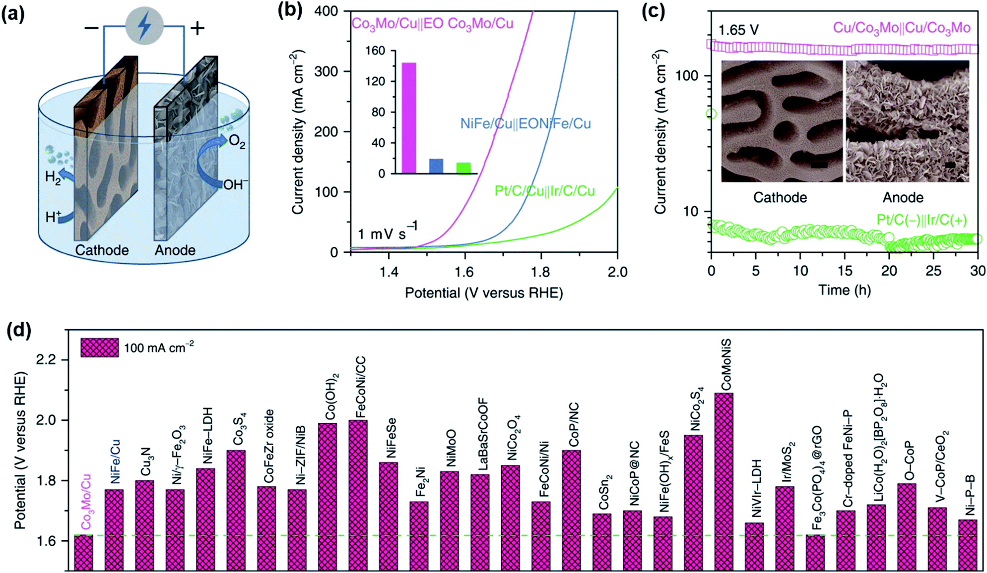 | ||
| Fig. 7 (a) Illustrated set-up of an overall water splitting cell with Co3Mo/Cu and EO Co3Mo/Cu electrodes as cathode and anode. (b) LSV curves for overall water splitting of Co3Mo/Cu‖EO Co3Mo/Cu and references in a 1 M KOH aqueous electrolyte and 0.5M NaCl (Inset: comparison of the received current density at a cell potential of 1.65 V). (c) Long term measurement of Co3Mo/Cu‖EO Co3Mo/Cu at 1.65 V in comparison to Pt/C/Cu‖Ir/C/Cu with inset depicting SEM images of Co3Mo/Cu cathode and EO Co3Mo/Cu anode after prolonged electrocatalysis (scale bar = 400nm). (d) The activity comparison of the cell potential of Co3Mo/Cu in alkaline media at a current density of 100mAcm−2 with various reported. Reprinted with permission from ref. 113, copyright 2020, Nature Publishing Group. | ||
It should be noted here that the activity presented in Tables 1 and 2, are only based on the overpotential, Tafel slope, electrolyte, and substrate effects. As the experimental conditions (pH, temperature, loading amount, film thickness, iR compensation, etc.) can differ in each case, the reader is referred to the respective references.
8. Insights into the active structures
Intermetallics are considered as a highly stable compound with higher resistance against chemical oxidation than single metal compounds due to their ordered structure with d-orbital interaction and covalent bonding.30,233 Currently, the high activity of intermetallic phases in the two different half-reactions of water splitting is often ascribed to the pronounced synergism of the different metallic species (active or electrically conductive), when no change in the original or pristine state of the structure was observed under catalytic conditions.96,171,229 If the catalyst is not stable during OER or HER catalysis, then it will be in its precatalytic state and the so-called pre-catalyst can transform in three possible ways: (i) near-surface, (ii) partial (core–shell), and (iii) complete transformation resulting into crystalline or amorphous structures (Fig. 8).16,234 In the case of near-surface, only the outermost layer of the catalysts are transformed typically by leaching or oxidation so that the reactants can participate in the reaction and contribute towards the net catalytic activity. The extent of transformation mainly depends upon the porosity or voids created by leaching (non)metals. In many cases, the structural transformation of the precatalyst is not continuous and ceased after a certain time interval when electrolyte can no longer penetrate through the precatalyst's core forming a stable core–shell phase. Under prolonged electrolysis, this process encompasses deep inside the core of the particles finally forming a stable active structure. The degree of conversion is not only limited to the leaching phenomenon but also depends on the size, morphology, composition of particles as well as the complex bonding situations of intermetallics. The transformation primarily results in increased ECSA, enhanced defect/disordered sites, higher electrical conductivity, surface or bulk activity, and structural porosity. In the following, we describe the type of transformation attained for intermetallic phases under electrocatalytic HER and OER conditions. | ||
| Fig. 8 Possible transformation pathways of a precatalyst into an active catalyst during catalytic OER and HER conditions. | ||
8.1 Active sites in HER
Most of the reported intermetallic compounds have shown no indication of transformation acting as chemically stable and highly resistant in a harsh HER environment.234 The high activity is explained by the specific surface composition of the formed materials.88 For instance, the remarkable HER performance of Ni and rare-earth-based intermetallics (Ni–LaNi5 and Ni–MmNi3.4–Co0.8Al0.8) was discussed in light of Brewer–Engel valence bond theory implying a synergistic effect of the hyper-electronic character of the Ni and the hypo-electronic character of the rare-earth element on the electrode surface to facilitate H+ adsorption (Heyrovsky step).222 The same synergistic effect of intermetallics was also revealed for Ni4Mo and Ni3Mo where d-orbitals of nickel (group VII) are more filled than those of molybdenum (group VI). Upon alloying, the d-orbitals interact and the catalyst becomes more active for HER when the d-band vacancies are introduced and becomes less active as d-band vacancies are filled.91 Similar observations have also been made for PtNi, LaNi5, TiNi3, ZrNi3, HfPd3, MoPt3, FeR (R = rare earth metals), and Ni–Mo-NGTs.89,104,138,176,222 In the case of NiIrRuAl, the charge transfer induced Ni gave rise to modified surface valence states that optimized the H+ adsorption and improved the catalytic HER activity.164 Pt2Si showed higher catalytic HER activity than Pt, by facilitating HO–H bond breaking and H+ adsorption through the incorporated Si and remained unchanged in the catalytic process.186 In addition, Pt3Ti139 and TiCo2 (ref. 109) also showed ideal conditions to adsorb H+ on the surface. Besides the optimal adsorption of H+ (Fig. 9c), the Pt3Ti proved to be very stable under electrocatalytic conditions in acidic HER. Only a minor change in activity was measured after 2000 CV cycles and the TEM showed that Pt3Ti phase was still intact (Fig. 9a and b).139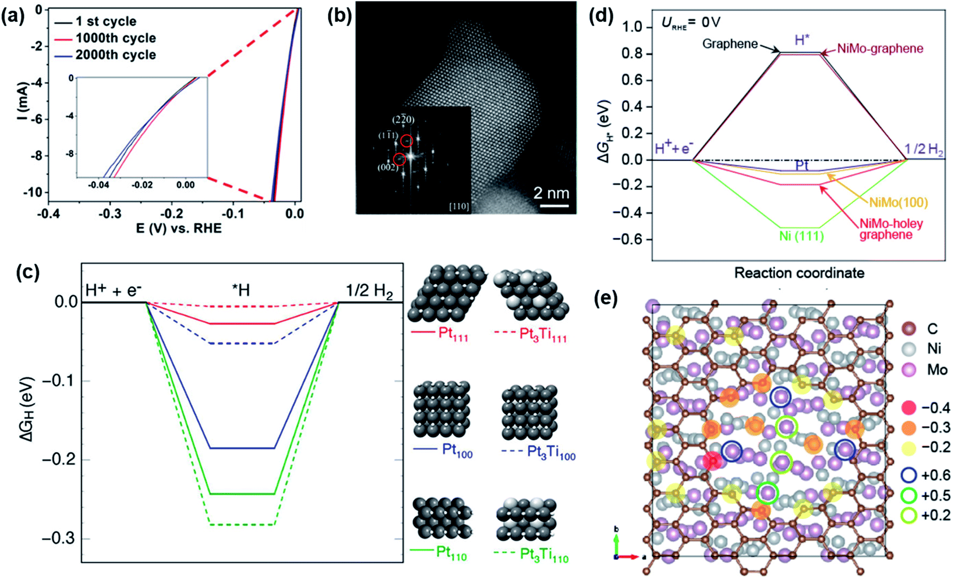 | ||
| Fig. 9 (a) HER LSV curves before and after the stability tests of intermetallic Pt3Ti. (b) HAADF-STEM image of Pt/Ti3C2Tx-550 (after 1000 cycles in HER) where the inset shows FFT pattern of a Pt3Ti NP. (c) DFT calculations of the free energy diagrams of the hydrogen evolution at the surfaces of Pt (111), Pt3Ti (111), Pt (100), Pt3Ti (100), Pt (110), and Pt3Ti (110). Figures (a–c) are reprinted with permission from ref. 139, copyright 2019, American Chemical Society (d) ΔG profiles calculated by DFT for the NiMo composites, showing the calculated free energy diagram of HER at the equilibrium potential for Pt, Ni(111), NiMo(100) graphene covered and bare as well as graphene covered and with a ∼1 nm hole, and a graphene sheet. (e) Bader charge population analysis of graphene covered NiMo(100) with a ∼1 nm hole. Figures (d and e) are reprinted with permission from ref. 130, copyright 2018, American Chemical Society. | ||
Along with the synergistic effect to enhance structural and electronic properties, and enhancement of the mass-specific surface area in the intermetallic phases has been observed, which significantly contributes to the HER activity.124,137,143 NiMo exhibited a much higher surface area and a larger turnover frequency per-surface atom resulting in a higher mass activity for HER. The tested intermetallic phase was stable in alkaline media and only degraded in acidic media. By the calculations of DFT and Bader charge population, it was demonstrated that NiMo had its optimal adsorption conditions and was stable when NiMo was covered with holey graphene and therefore possessed more active sites (Fig. 9d and e).206 By additionally covering the surface of NiMo with graphene, the dissolution of the intermetallic phase in acidic media was drastically reduced and enhanced the catalytic activity of the material.130 Ni50Mo40Ti10 and Ni50Mo50 were also found to be stable and highly active due to their enlarged surface area. Additionally, it was found that the presence of Ti in NiMo further increased the intrinsic activity for HER.168 The comparably high surface area that maximizes the exposure of active sites was also observed in Ti–Ni,196 Fe–Zn155 Pd2Si,125 Ni2Si,125 GaPt3,122 GaPd2,123 and Pt–Dy107 resulting in high HER performance. Jin et al. ascribed their efficiency and durability for their np-AlNiCoIrMo HEA to the high-entropy stabilizing effect of the quinary compound. The five different uniformly distributed elements with unique physiochemical properties attributed synergistically to the formation of the porous structure that was retained during HER.100 Similar conclusions were drawn for the FeCoNiAlTi HEI.162 Intriguingly, the bifunctional Co3Mo/Cu exhibited efficient HER and remained unchanged. The high activity of Co3Mo was attributed to the surfaces precisely composed of Co and Mo atoms, wherein their dissimilarity results in both ligand effect and strain effect to regulate the adsorption energies of the H* intermediate, leading to a high performance HER electrode.113
Apart from electrochemically stable electrodes, many reports show surface passivation and even transformation of the precatalyst during HER. In such cases, the transformation of the surface of the film or particles leads to a core–shell structure and the active materials typically exhibit an increased surface area.234 Despite reports on electrochemically stable Ni3Al electrodes for HER, Al-based electrodes tend to transform during catalysis due to Al leaching.93,94,235 Highly porous Ni3Al from Liu's group showed slight surface passivation after strongly alkaline (6 M KOH) HER catalysis. It was expected to form NiO and NiOOH/OOH on the surface, but it is unclear whether the formed species influenced the HER activity.93 In other reports, the Al leaching in alkaline solution is intended to increase the electrode activity by increasing the surface (porosity effect) through the created voids, and some phases were not stable and disintegrate during leaching.92 However, the intensity of the leaching process was dependent strongly on the initial stoichiometric and elemental composition, the structure, and the morphology of the starting material as well as the electrolyte.234 A loss of Al was also confirmed for Al7Cu4Ni@Cu4Ni in alkaline HER forming a core–shell structure. The stability of the material was ascribed to the stable Cu4Ni shell, in which the Ni atoms anchored with subsurface Al atoms forming strong Ni–Al bonds and suppress diffusion of Cu atoms.163 The same results were obtained for PdCu3 and PdBi2 where a loss of Cu and Bi resulted under HER forming in situ a Pd rich catalyst. Long-term HER experiments confirmed that the shell of the catalyst inhibited further leaching and remained stable once formed that indeed increased the H+ adsorption as well as the charge transfer through the catalyst.119,129 Analogous HER reaction pathways were observed when we investigated CoSn2 as a catalyst for water splitting. The surface leaching of Sn from the outermost layer of CoSn2 exposed abundant Co0 sites for HER for facile H+ adsorption and reduction to form H2 while unchanged bulk phase contributed in terms of electronic conductivity.221
A more drastic transformation of an intermetallic phase into an oxide phase during HER was observed in Ni–Co–Al on a Ni-foil by Zhou et al. X-ray photoelectron spectroscopy (XPS) data clearly revealed, that after HER, Al was oxidized into Al2O3; Ni into NiO and Al2NiO4 and Co into Co3O4 and Al2CoO4. Since no oxide species was present on the precatalyst material, the Al2NiO4/Al2CoO4 was considered as an active species contributing to the electrocatalytic performance towards HER in alkaline solution.111
8.2 Active sites in OER
In stark contrast to HER catalysts, the strongly oxidizing conditions of the OER force most of the non-oxides inexorably to form oxides and (oxy)hydroxides (at least at the surface) due to their thermodynamically more favorable stability.236 However, some of the reported intermetallic compounds show almost no or limited change in their crystal structure and morphology under OER conditions.234 For example, Mukherjee and co-workers reported intermetallic PtCo with CoOx composite for efficient OER and ORR. The sponge-shaped CoOx matrix surrounding PtCo NPs enforced synergic “spillover” effects and helped to preserve the structural and morphological integrity of PtCo NPs preventing their aggregation and dissolution in alkaline electrolytes.167 Likewise, the microstructure and element distribution of the np-AlNiCoIrMo HEA revealed no obvious microstructure coarsening and uniformly element distribution without aggregation after the OER durability test. It was stated that the bicontinuous nanoscale ligament-pore structure facilitates mass transport (both electrolyte and gas) and provided a conductive network for fast electron transfer and efficient electrochemical reactions.100 No visible transformation was reported for the intermetallic Ni/SiOC phase even after 10000 CV cycles of OER which was attributed to the presence of NiIII, giving increased conductivity to the material and providing higher affinity towards adsorption of OH* anions enhancing the OER.223 Retention of structural stability after OER was also reported for intermetallic AlNi3, AlNi3/Al3Ni5, and AlNi phases, however, a minor amount of Al leaching was unavoidable.169
As discussed earlier, in most cases, the transformation of the (pre)catalyst into the active species during OER catalysis is imminent. The nature of the formed catalyst is mainly defined by the structure of the precatalyst, electronic properties, the leaching ability and size of the leaching ion, and the transformation conditions strongly influenced by the pH of the electrolyte as well as the applied potential.16 The intermetallic NiSn synthesized by Jović et al. slowly oxidized on the surface into a β-NiOOH in alkaline OER that γ-NiOOH activated from bare Ni.227 Using Raman spectroscopy, Shen's group was also able to uncover in situ NiOOH active layer by etching of MoNi4 in alkaline OER conditions.131 The core–shell Cu1−xNNi3−y/FeNiCu, reported by Shao's group described the FeNiCu-(oxy)hydroxide as the active species in the HER process, that retained structural integrity post 24 h of OER.99 The group of Grin observed that the bulk Hf2B2Ir5 and major volume close to the surface did not change under the OER conditions. The formation of monoclinic HfO2 and IrOx(OH)y (SO4)z particles upon anodic treatment of the Hf2B2Ir5 was mainly related to the oxidation of the secondary phase HfB4Ir3 that was also present in minor amounts in addition to the self-controlled near-surface oxidation of Hf2B2Ir5. They concluded that the chemical bonding features of the Hf2B2Ir5 compound with a cage-like Ir–B framework, hosting Hf atoms, only allow near-surface oxidation and inhibit deep Ir leaching.112 Zhang and co-workers showed that the surface oxidation of NiIrRuAl led to an improvement of catalytic activity. By tuning the atomic ratio of Ir/Ru, it was demonstrated that a higher Ru content improves the intrinsic catalytic activity while more Ir effectively generates Ir oxides on the surface to retain the catalytic stability. More Ni content weakened the adsorption of oxygen-based intermediates by shifting down the Ir d-band center signifying its role in OER activity and it also leached from the surface structure leading to an increased concentration of oxygen species, drastically enhancing the OER activity.164
The persistent surface oxidation of intermetallics under OER often leads to a core–shell structure that usually consists of a crystalline or amorphously active shell and a conductive core that supports cooperative interactions of the elements.234 While thickness and properties of the surrounding layer vary depending on the starting material and transformation conditions, it is often observed that the oxide coating actively inhibits further oxidation of the material underneath.234,236 As an example, Ni2Ta, Co2Ta, and Fe2Ta anodes slowly corroded under acidic OER conditions and formed a protective oxide layer that indeed acted as a passivating oxide coating, allowing subsurface atoms to continue to participate in OER while limiting their dissolution.110 In another example, acid etching of IrNi to obtain nanocages induced an IrOx layer on the surface. This layer increased under continuous OER operation resulting in core–shell IrNi@IrOx. The unique feature of the inner lying IrNi and outer IrOx phase was concluded to be responsible for the high OER activity.120 In a recent approach, we observed similar transformations in FeSn2. After alkaline OER, the FeSn2 generated a goethite α-FeOOH shell with FeSn2 core. The α-FeOOH shell facilitated the OER while the intact intermetallic core enhanced electrical conductivity.102 Besides, the Ni2Si and NiSi prepared by Kumar et al. suffered substantial reorganization of the structure for alkaline OER. The SiOx species leached from the surface continuously to form an active NiOOH shell on both NiSi or Ni2Si.224
In many cases, the complete degradation of the precatalyst into a more crystalline or amorphous (oxy)hydroxide under OER has been reported. As the material is oxidized, it undergoes significant leaching of the nonmetallic component and facilitates major structural reorganization with substantially enhanced ECSA from the newly porous bulk-active structures that in turn increases the number of active sites for the OER.234 Different observations were made by Møller's group for their Al–Ni phase where they postulated that in alkaline conditions the material is thermodynamically not stable at zero potential and undergoes corrosion. Another possibility for dissolution was localized acid formation inside the porous structure during OER resulting from disturbances of oxygen bubbles on OH− migration into the inner active sites of the catalyst. As a consequence the pH is locally decreased, hence the structure is further weakened and corrosion will ultimately severely damage the structure.160 Similar observations were also made for intermetallic MnGa4 where three distinct crystalline MnOx phases: birnessite δ-MnO2, feitknechtite β-MnOOH, and hausmannite α-Mn3O4 were confirmed after the alkaline OER that was accompanied by an almost complete Ga loss from the structure (Fig. 10).97 The transformation trend was also extended for SSP-derived FeAs and NiGe precatalysts. In the case of FeAs, an active 2-line ferrihydrite phase was formed after alkaline OER with the severe dissolution of As in the structure. The Raman and in situ XAS described the reaction pathway and the defective edges/sites, as well as the presence of surface tetrahedral coordinated FeIII atoms, were ought to be the active centers for OER catalysis.149 On the other end, NiGe produced γ-NiOOH. The activity was attributed to the structural flexibility of Ni sites triggered by the defected structure with ionic intercalation of OH−/CO32− between the large interplanar spacing of γ-NiOOH, In both cases, the transformation resulted in higher ECSA values, and better electronic conductivities to promote favorable OER kinetics with improved charge transfer properties to facilitate the OER.105 Of late, we reported an intermetallic Fe6Ge5 as a novel alkaline OER precatalyst forming first an in situ metastable core–shell structure that slowly collapses in prolonged OER conditions finally to form a FeIIIOxHy.98
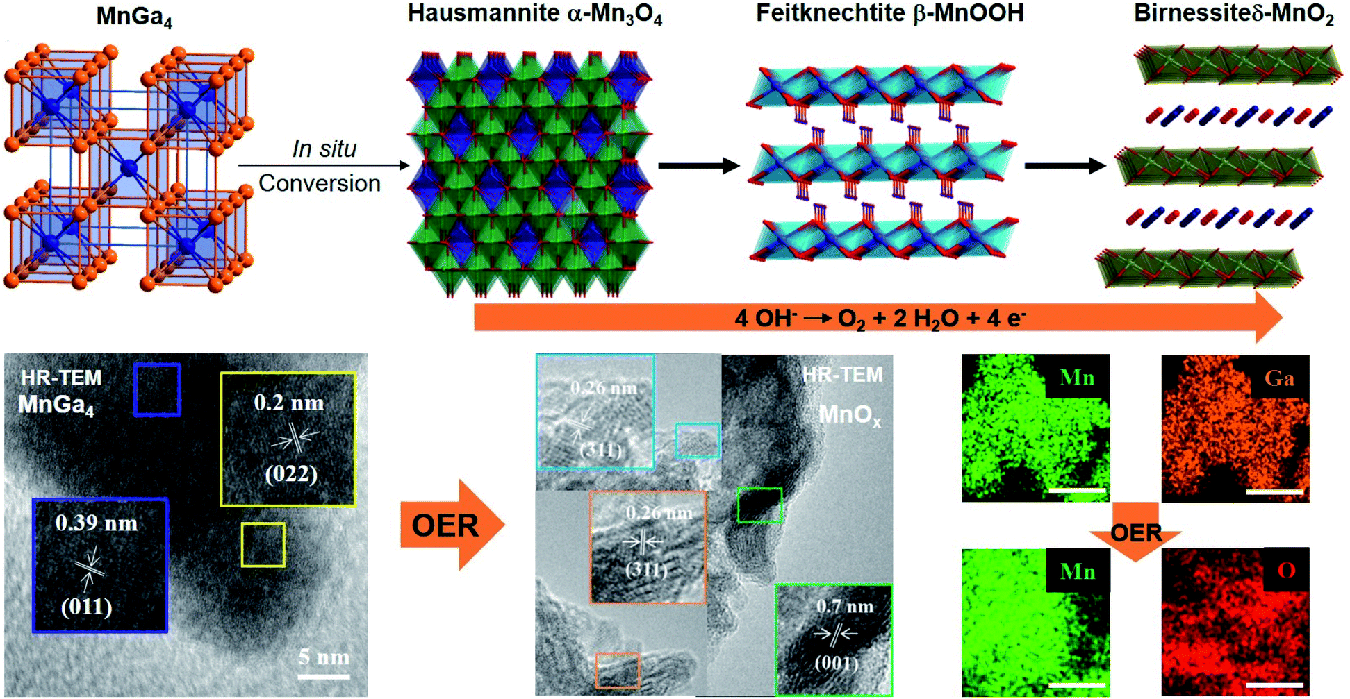 | ||
| Fig. 10 Proposed mechanism for the electroconversion of MnGa4 to δ-MnO2 with its intermediates (top). TEM images of MnGa4 and the transformed oxide species after OER in alkaline media (bottom left). EDX mapping of Mn and Ga in MnGa4 before alkaline OER and Mn and O mapping after. Adapted with permission from ref. 97, copyright 2019, Wiley-VCH. | ||
We recently investigated CoSn2 for overall water splitting where after alkaline OER, CoSn2 underwent a slow but rather complete structural transformation (Fig. 11). The loss of Sn from the structure of CoSn2 led to a disordered, defected, and vacant amorphous active material with a CoOx/CoOOH phase (with CoIII centered active species) that enables optimal adsorption of the oxygen species (Oad), thus facilitating the formation of adsorbed –OOH species (OOHad) by a nucleophilic attack, thereby promoting the deprotonation of OOHad to produce O2.221 However, in the case of HER, only surface Sn loss was observed exposing the Co0 site for H+ adsorption (Fig. 11).
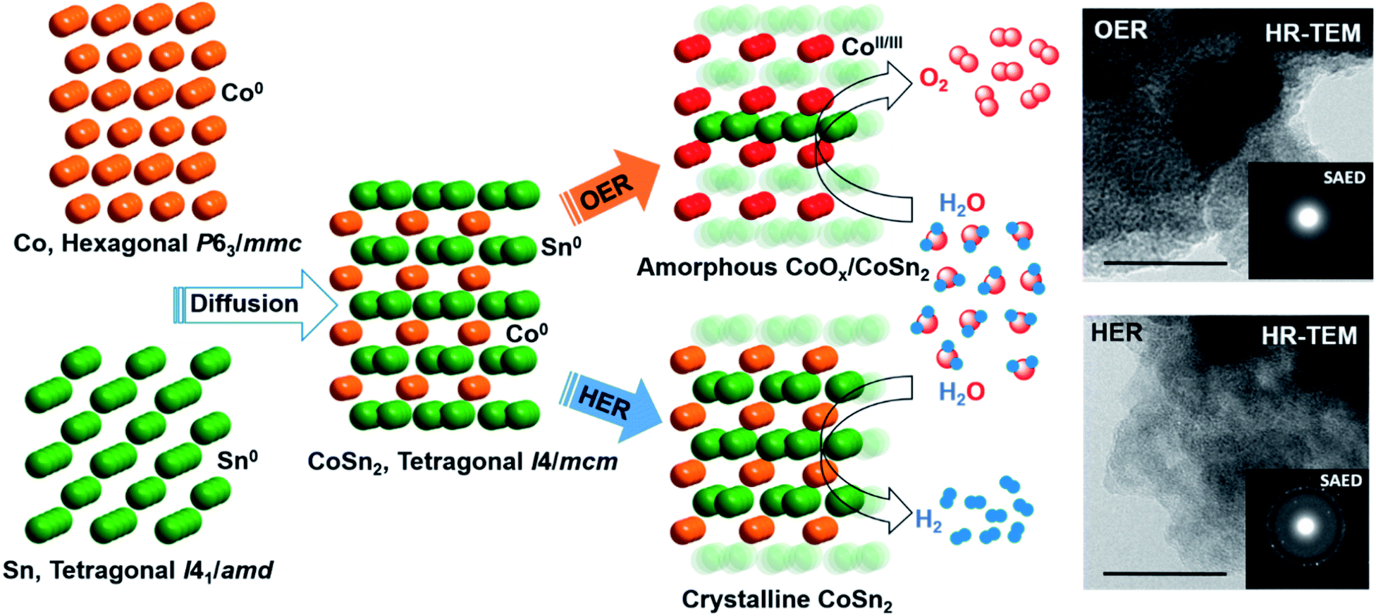 | ||
| Fig. 11 A synthetic approach to nanostructured CoSn2, with structural modification during alkaline HER and OER (left). TEM images of showing amorphous CoOx/CoSn2 after OER (top right) and crystalline CoSn2 after HER (bottom right) with SAED inset, scale bar = 10 nm. Adapted with permission from ref. 221 copyright 2018, Wiley-VCH. | ||
In all cases, the stability of the catalysts was also linked to the extent of structural transformations. If the transformation is very rapid and complete, no change in the stability curve is observed as the formed species are already sufficient to withhold the stable current under longer run.105 However, if the transformation is slower, an initial decrease in current was observed until a formation of core–shell is attained (not allowing further electrolyte permeability) and then a constant current at applied potentials is achieved.98 In both cases, the extent of transformation was found to be important to produce an enormous number of active sites, increased surface areas, or even electronic conductivity.
9. Conclusion and challenges
Intermetallic compounds have emerged as compelling advanced energy materials for HER, OER, and overall water splitting. In various examples, intermetallic catalysts are displayed to promote the challenging reactions of water splitting with enhanced activity, improved reaction kinetics, and long-lasting durability. In this perspective, we have highlighted the suitability of well-defined intermetallic (pre)catalysts for the design of high-performance electrocatalysts with complex interface structure, bonding characteristics, and electronic properties, which is essential to increase overall energetic efficiencies of the water-splitting reaction and stabilization of their active structures under operating conditions. Although substantial efforts have been devoted to exploring intermetallic compounds as novel catalysts for water splitting, they are relatively underdeveloped. Therefore, several critical aspects need to be taken into account for the further development of this field and are discussed below.One of the essential factors for designing an efficient electrocatalyst is by synthesizing the materials in nanoscale, increasing the number of active sites, active surface areas, and electronic conductivities. The properties of intermetallic compounds are closely associated with their size, shape, structure, composition, and crystal phase and hence, they must be tuned and optimized according to the need of electrocatalysis. In order to form an intermetallic compound, a large amount of energy is required, which is usually achieved with high-temperature annealing methods. Such solid-state techniques often predictably give rise to large agglomerated particles or even by-products and in most cases, with significantly decreased catalytic active surface areas.30 Thus, it is extremely interesting to design low-temperature novel synthetic strategies that can allow better atomic-level control over the stoichiometry, high dispersity of nanostructures with access to unique electronic and surface structures. In this regard, low-cost techniques such as wet impregnation, SSP, chemical reduction, and electrochemical approaches entail more attention. Similarly, looking at the various known classes of intermetallic compounds with different element combinations, a knowledge-guided simulation could also be highly important for their rational synthesis with desired HER and OER properties.28
Most importantly, it is now well-known that most of the intermetallic catalysts transform (either step-wise or completely) from their pristine state to active state under catalytic operating HER and OER conditions. Therefore, understanding the dynamic behavior of the catalyst through advanced ex situ and operando techniques to reveal the real active species, morphological and electronic changes, surface/bulk structure, and structure–activity relation during catalysis is of utmost significance. Indeed, efforts should also be devoted to testing the active intermetallic catalysts for OER and HER for a longer period at higher currents to observe their chemical stability. This will not only will help us to understand the reaction mechanism but also to further optimize the catalyst design with desired elements.
As the current studies have demonstrated the applicability of intermetallic compounds for electrocatalytic water splitting, it is now essential to examine them (either unifunctional or bifunctional) in industrially relevant conditions at elevated temperatures as well as at higher current densities in harsh alkaline or acidic environments. This step is pivotal, as the reaction conditions set for the lab-scale are entirely different when compared to the actual working electrolyzers. In addition to this, emphasis should also be given to the stability and the degradation of catalysts under operating conditions. Thus, future studies should be focussed on designing nanostructured intermetallic electrocatalysts with specific structure-types with porosity, precise control in their particle size and morphology with higher surface areas, enhanced electronic conductivity, structures with electrolyte permeability and bulk-activity, fast-redox switching sites, the maximum amount of edge sites, which have already been proven beneficial for non-oxidic materials.16,237 Like-wise, such designed intermetallics are expected to work under high current densities, elevated temperature, all-pH electrolytes, and for seawater splitting. In the near future, the research should also be concentrated on producing large electrodes with excellent mechanical and (electro)chemical stability, resistance to acidic/alkaline media, and bifunctionality.
The tunability of intermetallic materials by varying different metals could make this class of materials also interesting for electrocatalytic applications beyond water-splitting. In this context, we recently combined the electrochemical water-splitting and selective (almost 100%) oxygenation of organic substrates through in situ surface modification of intermetallic FeSn2 precatalyst. Selective oxygenation is a demanding approach and bears higher economic value than oxygen produced by water splitting. Therefore, intermetallic catalysts could be used to further explore this nascent field where H2 and oxygenated products can be liberated simultaneously, making it a lucrative technology. Alternatively, the same electrochemical technology with intermetallics can be applied in non-aqueous solvents to drive the other essential transformations such as regeneration of the triphenylphosphine from triphenylphosphine oxide as well as a one-pot Wittig olefination reaction that presently best driven by noble-metal catalysts.238
Furthermore, the scope of the intermetallics can easily be extended electrochemical carbon dioxide (CO2) reduction, a promising reaction to mitigate CO2 emissions, where presently transition metals (in particularly Cu) have been used predominantly to yield high-end multicarbon products. Notably, the intermetallics can also be of special interest for the kinetically sluggish oxygen reduction reaction (ORR), an important cathodic reaction of fuel cell which is presently mediated by the metals, alloys, and carbons, etc. Another alternative strategy would be to utilize intermetallics to achieve a systematic electrochemical reduction of heavy non-metal oxides with very strong E–O Bonds (E = Si, P, S).239 Besides, intermetallics have also shown promising electrocatalytic behavior methanol oxidation reaction,240 surface coatings,241 and supercapacitors. Although intermetallics is relatively an unexplored field for electrocatalysis, more fundamental and applied research pursued simultaneously to uncover novel classes of materials and study their intriguing unusual properties toward energy applications.
Author contributions
C. W. conducted the literature research and wrote the first draft of the manuscript. P. W. M. initiated the overall idea and contributed to the planning and writing of the manuscript. M. D. and P.W. M. discussed, supervised, and edited the final version of the perspective.Conflicts of interest
There are no conflicts to declare.Acknowledgements
The authors greatly acknowledge support from Deutsche Forschungsgemeinschaft (DFG, German Research Foundation) under Germany's Excellence Strategy – EXC 2008/1-390540038 – UniSysCat.Notes and references
- C. Panda, P. W. Menezes and M. Driess, Angew. Chem., Int. Ed., 2018, 57, 11130–11139 CrossRef CAS PubMed.
- M. G. Walter, E. L. Warren, J. R. McKone, S. W. Boettcher, Q. Mi, E. A. Santori and N. S. Lewis, Chem. Rev., 2010, 110, 6446–6473 CrossRef CAS PubMed.
- V. R. Stamenkovic, D. Strmcnik, P. P. Lopes and N. M. Markovic, Nat. Mater., 2016, 16, 57 CrossRef PubMed.
- T. Faunce, S. Styring, M. R. Wasielewski, G. W. Brudvig, A. W. Rutherford, J. Messinger, A. F. Lee, C. L. Hill, H. deGroot, M. Fontecave, D. R. MacFarlane, B. Hankamer, D. G. Nocera, D. M. Tiede, H. Dau, W. Hillier, L. Wang and R. Amal, Energy Environ. Sci., 2013, 6, 1074 RSC.
- N. S. Lewis, Science, 2007, 315, 798–801 CrossRef CAS PubMed.
- L. Schlapbach and A. Züttel, Nature, 2001, 414, 353–358 CrossRef CAS PubMed.
- I. Staffell, D. Scamman, A. Velazquez Abad, P. Balcombe, P. E. Dodds, P. Ekins, N. Shah and K. R. Ward, Energy Environ. Sci., 2019, 12, 463–491 RSC.
- M. M. Najafpour, G. Renger, M. Holynska, A. N. Moghaddam, E.-M. Aro, R. Carpentier, H. Nishihara, J. J. Eaton-Rye, J.-R. Shen and S. I. Allakhverdiev, Chem. Rev., 2016, 116, 2886–2936 CrossRef CAS PubMed.
- G. Glenk and S. Reichelstein, Nat. Energy, 2019, 4, 216–222 CrossRef CAS.
- A. Buttler and H. Spliethoff, Renewable Sustainable Energy Rev., 2018, 82, 2440–2454 CrossRef CAS.
- H. Lee, B. Lee, M. Byun and H. Lim, Energy Convers. Manage., 2020, 224, 113477 CrossRef CAS.
- M. J. Craig and M. García-Melchor, Nat. Catal., 2020, 3, 967–968 CrossRef CAS.
- E. Fabbri, A. Habereder, K. Waltar, R. Kötz and T. J. Schmidt, Catal. Sci. Technol., 2014, 4, 3800–3821 RSC.
- C. C. L. McCrory, S. Jung, J. C. Peters and T. F. Jaramillo, J. Am. Chem. Soc., 2013, 135, 16977–16987 CrossRef CAS PubMed.
- J. Kibsgaard and I. Chorkendorff, Nat. Energy, 2019, 4, 430–433 CrossRef.
- J. N. Hausmann, S. Mebs, K. Laun, I. Zebger, H. Dau, P. W. Menezes and M. Driess, Energy Environ. Sci., 2020, 13, 3607–3619 RSC.
- J. N. Hausmann, E. M. Heppke, R. Beltrán-Suito, J. Schmidt, M. Mühlbauer, M. Lerch, P. W. Menezes and M. Driess, ChemCatChem, 2020, 12, 1161–1168 CrossRef CAS.
- B. Chakraborty, R. Beltrán-Suito, V. Hlukhyy, J. Schmidt, P. W. Menezes and M. Driess, ChemSusChem, 2020, 13, 3222–3229 CrossRef CAS PubMed.
- C. Walter, P. W. Menezes, S. Orthmann, J. Schuch, P. Connor, B. Kaiser, M. Lerch and M. Driess, Angew. Chem., Int. Ed., 2018, 57, 698–702 CrossRef CAS PubMed.
- P. W. Menezes, A. Indra, C. Das, C. Walter, C. Göbel, V. Gutkin, D. Schmeißer and M. Driess, ACS Catal., 2017, 7, 103–109 CrossRef CAS.
- P. W. Menezes, C. Panda, C. Walter, M. Schwarze and M. Driess, Adv. Funct. Mater., 2019, 414, 1808632 CrossRef.
- P. W. Menezes, C. Panda, S. Loos, F. Bunschei-Bruns, C. Walter, M. Schwarze, X. Deng, H. Dau and M. Driess, Energy Environ. Sci., 2018, 11, 1287–1298 RSC.
- P. W. Menezes, A. Indra, I. Zaharieva, C. Walter, S. Loos, S. Hoffmann, R. Schlögl, H. Dau and M. Driess, Energy Environ. Sci., 2019, 12, 988–999 RSC.
- P. W. Menezes, C. Walter, B. Chakraborty, J. N. Hausmann, I. Zaharieva, A. Frick, E. von Hauff, H. Dau and M. Driess, Adv. Mater., 2021, 33, e2004098 CrossRef PubMed.
- S. Gupta, M. K. Patel, A. Miotello and N. Patel, Adv. Funct. Mater., 2020, 30, 1906481 CrossRef CAS.
- C. Panda, P. W. Menezes, C. Walter, S. Yao, M. E. Miehlich, V. Gutkin, K. Meyer and M. Driess, Angew. Chem., Int. Ed., 2017, 56, 10506–10510 CrossRef CAS PubMed.
- H. Vrubel and X. Hu, Angew. Chem., Int. Ed., 2012, 51, 12703–12706 CrossRef CAS PubMed.
- C. Panda, P. W. Menezes, S. Yao, J. Schmidt, C. Walter, J. N. Hausmann and M. Driess, J. Am. Chem. Soc., 2019, 141, 13306–13310 CrossRef CAS PubMed.
- S. Furukawa and T. Komatsu, ACS Catal., 2017, 7, 735–765 CrossRef CAS.
- L. Rößner and M. Armbrüster, ACS Catal., 2019, 9, 2018–2062 CrossRef.
- H. Wendt and G. Imarisio, J. Appl. Electrochem., 1988, 18, 1–14 CrossRef CAS.
- K. Zeng and D. Zhang, Prog. Energy Combust. Sci., 2010, 36, 307–326 CrossRef CAS.
- Z. Yan, H. Liu, Z. Hao, M. Yu, X. Chen and J. Chen, Chem. Sci., 2020, 11, 10614–10625 RSC.
- I. C. Man, H.-Y. Su, F. Calle-Vallejo, H. A. Hansen, J. Martínez, N. G. Inoglu, J. Kitchin, T. F. Jaramillo, J. K. Nørskov and J. Rossmeisl, ChemCatChem, 2011, 3, 1159–1165 CrossRef CAS.
- J. Suntivich, E. E. Perry, H. A. Gasteiger and Y. Shao-Horn, Electrocatalysis, 2013, 4, 49–55 CrossRef CAS.
- A. J. Bard and L. R. Faulkner, Electrochemical Methods. Fundamentals and Applications, 2nd edn, John Wiley & Sons Inc., New York, 2001 Search PubMed.
- J. Wang, Analytical Electrochemistry, 3rd edn, Wiley-VCH, Hoboken, N.J. USA, 2006 Search PubMed.
- D. Pletcher, R. Greff, R. Peat, L. M. Peter and J. Robinson, Instrumental Methods in Electrochemistry, 1st edn, Horwood Publishing, Chichester, 2001 Search PubMed.
- J. Wei, M. Zhou, A. Long, Y. Xue, H. Liao, C. Wei and Z. J. Xu, Nano-Micro Lett., 2018, 10, 75 CrossRef CAS PubMed.
- N.-T. Suen, S.-F. Hung, Q. Quan, N. Zhang, Y.-J. Xu and H. M. Chen, Chem. Soc. Rev., 2017, 46, 337–365 RSC.
- Y. Cheng and S. P. Jiang, Prog. Nat. Sci.: Mater. Int., 2015, 25, 545–553 CrossRef CAS.
- H. Dau, C. Limberg, T. Reier, M. Risch, S. Roggan and P. Strasser, ChemCatChem, 2010, 2, 724–761 CrossRef CAS.
- R. Parsons, Trans. Faraday Soc., 1958, 54, 1053 RSC.
- B. E. Conway and B. V. Tilak, Electrochim. Acta, 2002, 47, 3571–3594 CrossRef CAS.
- S. Anantharaj, S. R. Ede, K. Karthick, S. Sam Sankar, K. Sangeetha, P. E. Karthik and S. Kundu, Energy Environ. Sci., 2018, 11, 744–771 RSC.
- S. Anantharaj, S. R. Ede, K. Sakthikumar, K. Karthick, S. Mishra and S. Kundu, ACS Catal., 2016, 6, 8069–8097 CrossRef CAS.
- T. J. Meyer, M. H. V. Huynh and H. H. Thorp, Angew. Chem., Int. Ed., 2007, 46, 5284–5304 CrossRef CAS PubMed.
- J. O. Bockris, J. Chem. Phys., 1956, 24, 817–827 CrossRef CAS.
- J. Rossmeisl, Z.-W. Qu, H. Zhu, G.-J. Kroes and J. K. Nørskov, J. Electroanal. Chem., 2007, 607, 83–89 CrossRef CAS.
- B. E. Conway and B. V. Tilak, Adv. Catal., 1992, 38, 1–147 CAS.
- D. E. Hall, J. Electrochem. Soc., 1983, 130, 317 CrossRef CAS.
- T. Shinagawa, A. T. Garcia-Esparza and K. Takanabe, Sci. Rep., 2015, 5, 13801 CrossRef PubMed.
- S. Anantharaj, S. Noda, V. R. Jothi, S. Yi, M. Driess and P. W. Menezes, Angew. Chem., Int. Ed., 2021 DOI:10.1002/anie.202015738.
- K. S. Joya, Y. F. Joya, K. Ocakoglu and R. van de Krol, Angew. Chem., Int. Ed., 2013, 52, 10426–10437 CrossRef CAS PubMed.
- D. Voiry, M. Chhowalla, Y. Gogotsi, N. A. Kotov, Y. Li, R. M. Penner, R. E. Schaak and P. S. Weiss, ACS Nano, 2018, 12, 9635–9638 CrossRef CAS PubMed.
- S. Anantharaj, S. Noda, M. Driess and P. W. Menezes, ACS Energy Lett., 2021, 1607–1611 CrossRef CAS.
- E. Antolini, ACS Catal., 2014, 4, 1426–1440 CrossRef CAS.
- M. S. Burke, L. J. Enman, A. S. Batchellor, S. Zou and S. W. Boettcher, Chem. Mater., 2015, 27, 7549–7558 CrossRef CAS.
- J. Zhang, H. B. Tao, M. Kuang, H. B. Yang, W. Cai, Q. Yan, Q. Mao and B. Liu, ACS Catal., 2020, 10, 8597–8610 CrossRef CAS.
- D. D. Macdonald, Electrochim. Acta, 2006, 51, 1376–1388 CrossRef CAS.
- V. F. Lvovich, Impedance Spectroscopy: Applications to Electrochemical and Dielectric Phenomena, 1st edn, John Wiley & Sons Inc, Hoboken, N.J., 2012 Search PubMed.
- S. Trasatti and O. A. Petrii, Pure Appl. Chem., 1991, 63, 711–734 CAS.
- Y. Yoon, B. Yan and Y. Surendranath, J. Am. Chem. Soc., 2018, 140, 2397–2400 CrossRef CAS.
- H. Li, S. Chen, X. Jia, B. Xu, H. Lin, H. Yang, L. Song and X. Wang, Nat. Commun., 2017, 8, 15377 CrossRef CAS PubMed.
- S. Brunauer, P. H. Emmett and E. Teller, J. Am. Chem. Soc., 1938, 60, 309–319 CrossRef CAS.
- S. Jung, C. C. L. McCrory, I. M. Ferrer, J. C. Peters and T. F. Jaramillo, J. Mater. Chem. A, 2016, 4, 3068–3076 RSC.
- X. Zhao, P. Pachfule, S. Li, T. Langenhahn, M. Ye, C. Schlesiger, S. Praetz, J. Schmidt and A. Thomas, J. Am. Chem. Soc., 2019, 141, 6623–6630 CrossRef CAS PubMed.
- C. Chen, D. Yan, Y. Wang, Y. Zhou, Y. Zou, Y. Li and S. Wang, Small, 2019, 15, E1805029 CrossRef PubMed.
- U. Divya Madhuri and T. P. Radhakrishnan, ChemElectroChem, 2019, 6, 1984–1989 CrossRef CAS.
- B. M. Hunter, H. B. Gray and A. M. Müller, Chem. Rev., 2016, 116, 14120–14136 CrossRef CAS PubMed.
- A. B. Laursen, A. S. Varela, F. Dionigi, H. Fanchiu, C. Miller, O. L. Trinhammer, J. Rossmeisl and S. Dahl, J. Chem. Educ., 2012, 89, 1595–1599 CrossRef CAS.
- Q. Liang, G. Brocks and A. Bieberle-Hütter, JPhys Energy, 2021, 3, 26001 CrossRef.
- M. Sankar, N. Dimitratos, P. J. Miedziak, P. P. Wells, C. J. Kiely and G. J. Hutchings, Chem. Soc. Rev., 2012, 41, 8099–8139 RSC.
- K. H. J. Buschow, Rep. Prog. Phys., 1977, 40, 1179–1256 CrossRef CAS.
- J. Osswald, R. Giedigkeit, R. E. Jentoft, M. Armbrüster, F. Girgsdies, K. Kovnir, T. Ressler, Y. Grin and R. Schlögl, J. Catal., 2008, 258, 210–218 CrossRef CAS.
- M. Armbrüster, R. Schlögl and Y. Grin, Sci. Technol. Adv. Mater., 2014, 15, 34803 CrossRef PubMed.
- D. Li, L. Wang, M. Koike and K. Tomishige, J. Jpn. Pet. Inst., 2013, 56, 253–266 CrossRef CAS.
- V. Y. Verchenko, A. A. Tsirlin, d. Kasinathan, S. v. Zhurenko, A. A. Gippius and A. v. Shevelkov, Phys. Rev. Mater., 2018, 2, 44408 CrossRef CAS.
- F. Gao and D. W. Goodman, Chem. Soc. Rev., 2012, 41, 8009–8020 RSC.
- A. Stein, S. W. Keller and T. E. Mallouk, Science, 1993, 259, 1558–1564 CrossRef CAS PubMed.
- H. Kohlmann, Eur. J. Inorg. Chem., 2019, 2019, 4174–4180 CrossRef CAS.
- M. Tabuchi, M. Takahashi and F. Kanamaru, J. Alloys Compd., 1994, 210, 143–148 CrossRef CAS.
- R. Reddy, A. Yahya and L. Brewer, J. Alloys Compd., 2001, 321, 223–227 CrossRef CAS.
- L. Jia, J. R. Sun, H. W. Zhang, F. X. Hu, C. Dong and B. G. Shen, J. Phys.: Condens. Matter, 2006, 18, 9999–10007 CrossRef CAS.
- Y. Grin, F. R. Wagner, M. Armbrüster, M. Kohout, A. Leithe-Jasper, U. Schwarz, U. Wedig and H. Georg von Schnering, J. Solid State Chem., 2006, 179, 1707–1719 CrossRef CAS.
- M. Armbrüster, W. Schnelle, R. Cardoso-Gil and Y. Grin, Chem.–Eur. J., 2010, 16, 10357–10365 CrossRef PubMed.
- M. H. Miles, J. Electroanal. Chem. Interfacial Electrochem., 1975, 60, 89–96 CrossRef CAS.
- A. Bélanger and A. K. Vijh, Int. J. Hydrogen Energy, 1987, 12, 227–233 CrossRef.
- F. Rosalbino, D. Macciò, E. Angelini, A. Saccone and S. Delfino, J. Alloys Compd., 2005, 403, 275–282 CrossRef CAS.
- B. Shen, Y. He, W. Li, Z. Wang, L. Yu, Y. Jiang, X. Liu, J. Kang, H. Gao and N. Lin, Mater. Des., 2020, 191, 108645 CrossRef CAS.
- M. Gennero de Chialvo and A. Chialvo, J. Electroanal. Chem., 1998, 448, 87–93 CrossRef CAS.
- L. Birry and A. Lasia, J. Appl. Electrochem., 2004, 34, 735–749 CrossRef CAS.
- H. Dong, T. Lei, Y. He, N. Xu, B. Huang and C. T. Liu, Int. J. Hydrogen Energy, 2011, 36, 12112–12120 CrossRef CAS.
- L. Wu, Y. He, T. Lei, B. Nan, N. Xu, J. Zou, B. Huang and C. T. Liu, Mater. Chem. Phys., 2013, 141, 553–561 CrossRef CAS.
- M. Han, S. Li, C. Li, J. Wu, J. Han, N. Wang, Y. Liu and H. Liang, J. Alloys Compd., 2020, 844, 156094 CrossRef CAS.
- M. Wang, W. Zhang, F. Zhang, Z. Zhang, B. Tang, J. Li and X. Wang, ACS Catal., 2019, 9, 1489–1502 CrossRef CAS.
- P. W. Menezes, C. Walter, J. N. Hausmann, R. Beltrán-Suito, C. Schlesiger, S. Praetz, V. Yu Verchenko, A. V. Shevelkov and M. Driess, Angew. Chem., Int. Ed., 2019, 58, 16569–16574 CrossRef CAS.
- J. N. Hausmann, R. A. Khalaniya, C. Das, I. Remy-Speckmann, S. Berendts, A. V. Shevelkov, M. Driess and P. W. Menezes, Chem. Commun., 2021, 57, 2184–2187 RSC.
- Y. Zhu, G. Chen, Y. Zhong, Y. Chen, N. Ma, W. Zhou and Z. Shao, Nat. Commun., 2018, 9, 2326 CrossRef PubMed.
- Z. Jin, J. Lv, H. Jia, W. Liu, H. Li, Z. Chen, X. Lin, G. Xie, X. Liu, S. Sun and H.-J. Qiu, Small, 2019, 15, e1904180 CrossRef PubMed.
- Z. Ding, J. Bian, S. Shuang, X. Liu, Y. Hu, C. Sun and Y. Yang, Adv. Sustainable Syst., 2020, 4, 1900105 CrossRef CAS.
- B. Chakraborty, R. Beltrán-Suito, J. N. Hausmann, S. Garai, M. Driess and P. W. Menezes, Adv. Energy Mater., 2020, 10, 2001377 CrossRef CAS.
- K. Chen, S. Kim, R. Rajendiran, K. Prabakar, G. Li, Z. Shi, C. Jeong, J. Kang and O. L. Li, J. Colloid Interface Sci., 2021, 582, 977–990 CrossRef CAS PubMed.
- T. Wang, Y. Guo, Z. Zhou, X. Chang, J. Zheng and X. Li, ACS Nano, 2016, 10, 10397–10403 CrossRef CAS PubMed.
- P. W. Menezes, S. Yao, R. Beltrán-Suito, J. N. Hausmann, P. V. Menezes and M. Driess, Angew. Chem., Int. Ed., 2021, 60, 4690–4697 CrossRef.
- R. Knight, R. W. Smith and D. Apelian, Int. Mater. Rev., 1991, 36, 221–252 CrossRef CAS.
- D. Santos, B. Šljukić, C. Sequeira, D. Macciò, A. Saccone and J. L. Figueiredo, Energy, 2013, 50, 486–492 CrossRef CAS.
- I. Antonyshyn, A. M. Barrios Jiménez, O. Sichevych, U. Burkhardt, I. Veremchuk, M. Schmidt, A. Ormeci, I. Spanos, A. Tarasov, D. Teschner, G. Algara-Siller, R. Schlögl and Y. Grin, Angew. Chem., Int. Ed., 2020, 59, 16770–16776 CrossRef CAS PubMed.
- P. Zhang, H.-G. Xue and N.-T. Suen, Chem. Commun., 2019, 55, 14406–14409 RSC.
- J. S. Mondschein, K. Kumar, C. F. Holder, K. Seth, H. Kim and R. E. Schaak, Inorg. Chem., 2018, 57, 6010–6015 CrossRef CAS PubMed.
- F. Zhou, Y. Zhou, M. Jiang, J. Liang, C. Fu, C. Wang, J. Liu, H. Gao, M. Kang and J. Wang, Mater. Lett., 2020, 272, 127831 CrossRef CAS.
- A. M. Barrios Jiménez, U. Burkhardt, R. Cardoso-Gil, K. Höfer, S. G. Altendorf, R. Schlögl, Y. Grin and I. Antonyshyn, ACS Appl. Energy Mater., 2020, 3, 11042–11052 CrossRef.
- H. Shi, Y.-T. Zhou, R.-Q. Yao, W.-B. Wan, X. Ge, W. Zhang, Z. Wen, X.-Y. Lang, W.-T. Zheng and Q. Jiang, Nat. Commun., 2020, 11, 2940 CrossRef CAS PubMed.
- Y. Yao, X.-K. Gu, D. He, Z. Li, W. Liu, Q. Xu, T. Yao, Y. Lin, H.-J. Wang, C. Zhao, X. Wang, P. Yin, H. Li, X. Hong, S. Wei, W.-X. Li, Y. Li and Y. Wu, J. Am. Chem. Soc., 2019, 141, 19964–19968 CrossRef CAS PubMed.
- H. Bönnemann and R. M. Richards, Eur. J. Inorg. Chem., 2001, 2001, 2455–2480 CrossRef.
- C. Burda, X. Chen, R. Narayanan and M. A. El-Sayed, Chem. Rev., 2005, 105, 1025–1102 CrossRef CAS PubMed.
- D. Wang, Q. Peng and Y. Li, Nano Res., 2010, 3, 574–580 CrossRef CAS.
- M. Zhou, C. Li and J. Fang, Chem. Rev., 2021, 121, 736–795 CrossRef CAS.
- S. Sarkar, U. Subbarao and S. C. Peter, J. Mater. Chem. A, 2017, 5, 15950–15960 RSC.
- H. Jin, Y. Hong, J. Yoon, A. Oh, N. K. Chaudhari, H. Baik, S. H. Joo and K. Lee, Nano Energy, 2017, 42, 17–25 CrossRef CAS.
- Á. Coogan and Y. K. Gun'ko, Mater. Adv., 2021, 2, 146–164 RSC.
- S.-C. Lim, C.-Y. Chan, K.-T. Chen and H.-Y. Tuan, Electrochim. Acta, 2019, 297, 288–296 CrossRef CAS.
- S.-C. Lim, C.-Y. Chan, K.-T. Chen and H.-Y. Tuan, Nanoscale, 2019, 11, 8518–8527 RSC.
- S.-C. Lim, M.-C. Hsiao, M.-D. Lu, Y.-L. Tung and H.-Y. Tuan, Nanoscale, 2018, 10, 16657–16666 RSC.
- J. M. McEnaney and R. E. Schaak, Inorg. Chem., 2015, 54, 707–709 CrossRef CAS PubMed.
- J. Xie, X. B. Zhao, G. S. Cao and J. P. Tu, J. Power Sources, 2007, 164, 386–389 CrossRef CAS.
- D. Sun, L. Si, G. Fu, C. Liu, D. Sun, Y. Chen, Y. Tang and T. Lu, J. Power Sources, 2015, 280, 141–146 CrossRef CAS.
- B. Y. Xia, H. B. Wu, X. Wang and X. W. Lou, J. Am. Chem. Soc., 2012, 134, 13934–13937 CrossRef CAS PubMed.
- R. Jana, A. Bhim, P. Bothra, S. K. Pati and S. C. Peter, ChemSusChem, 2016, 9, 2922–2927 CrossRef CAS PubMed.
- Y. Ito, T. Ohto, D. Hojo, M. Wakisaka, Y. Nagata, L. Chen, K. Hu, M. Izumi, J. Fujita and T. Adschiri, ACS Catal., 2018, 8, 3579–3586 CrossRef CAS.
- Y. Jin, X. Yue, C. Shu, S. Huang and P. K. Shen, J. Mater. Chem. A, 2017, 5, 2508–2513 RSC.
- J. Xu, Z. Lian, B. Wei, Y. Li, O. Bondarchuk, N. Zhang, Z. Yu, A. Araujo, I. Amorim, Z. Wang, B. Li and L. Liu, ACS Catal., 2020, 10, 3571–3579 CrossRef CAS.
- S. P. Jiang, Mater. Sci. Eng. A, 2006, 418, 199–210 CrossRef.
- X. Ji, K. T. Lee, R. Holden, L. Zhang, J. Zhang, G. A. Botton, M. Couillard and L. F. Nazar, Nat. Chem., 2010, 2, 286–293 CrossRef CAS PubMed.
- Z. Liu, B. Liu, D. Ding, M. Liu, F. Chen and C. Xia, J. Power Sources, 2013, 237, 243–259 CrossRef CAS.
- G. Saravanan, R. Khobragade, L. Chand Nagar and N. Labhsetwar, RSC Adv., 2016, 6, 85634–85642 RSC.
- L.-W. Chen, X. Guo, R.-Y. Shao, Q.-Q. Yan, L.-L. Zhang, Q.-X. Li and H.-W. Liang, Nano Energy, 2021, 81, 105636 CrossRef CAS.
- H. Chen, G. Wang, T. Gao, Y. Chen, H. Liao, X. Guo, H. Li, R. Liu, M. Dou, S. Nan and Q. He, J. Phys. Chem. C, 2020, 124, 5036–5045 CrossRef CAS.
- Z. Li, Z. Qi, S. Wang, T. Ma, L. Zhou, Z. Wu, X. Luan, F.-Y. Lin, M. Chen, J. T. Miller, H. Xin, W. Huang and Y. Wu, Nano Lett., 2019, 19, 5102–5108 CrossRef CAS PubMed.
- S. Polarz, A. V. Orlov, M. W. E. van den Berg and M. Driess, Angew. Chem., Int. Ed., 2005, 44, 7892–7896 CrossRef CAS PubMed.
- C. L. Daniels, D. L. Mendivelso-Perez, B. A. Rosales, D. You, S. Sahu, J. S. Jones, E. A. Smith, F. P. Gabbaï and J. Vela, ACS Omega, 2019, 4, 5197–5203 CrossRef CAS PubMed.
- J. Pfrommer, M. Lublow, A. Azarpira, C. Göbel, M. Lücke, A. Steigert, M. Pogrzeba, P. W. Menezes, A. Fischer, T. Schedel-Niedrig and M. Driess, Angew. Chem., Int. Ed., 2014, 53, 5183–5187 CAS.
- P. M. Csernica, J. R. McKone, C. R. Mulzer, W. R. Dichtel, H. D. Abruña and F. J. DiSalvo, ACS Catal., 2017, 7, 3375–3383 CrossRef CAS.
- A. Indra, P. W. Menezes, I. Zaharieva, E. Baktash, J. Pfrommer, M. Schwarze, H. Dau and M. Driess, Angew. Chem., Int. Ed., 2013, 52, 13206–13210 CrossRef CAS PubMed.
- S. Yao, V. Forstner, P. W. Menezes, C. Panda, S. Mebs, E. M. Zolnhofer, M. E. Miehlich, T. Szilvási, N. Ashok Kumar, M. Haumann, K. Meyer, H. Grützmacher and M. Driess, Chem. Sci., 2018, 9, 8590–8597 RSC.
- R. Beltrán-Suito, P. W. Menezes and M. Driess, J. Mater. Chem. A, 2019, 7, 15749–15756 RSC.
- A. Indra, P. W. Menezes, I. Zaharieva, H. Dau and M. Driess, J. Mater. Chem. A, 2020, 8, 2637–2643 RSC.
- B. Chakraborty, S. Kalra, R. Beltrán-Suito, C. Das, T. Hellmann, P. W. Menezes and M. Driess, Chem.–Asian J., 2020, 15, 852–859 CrossRef CAS PubMed.
- R. Beltrán-Suito, V. Forstner, J. N. Hausmann, S. Mebs, J. Schmidt, I. Zaharieva, K. Laun, I. Zebger, H. Dau, P. W. Menezes and M. Driess, Chem. Sci., 2020, 11, 11834–11842 RSC.
- B. P. Daly and F. J. Barry, Int. Mater. Rev., 2003, 48, 326–338 CrossRef CAS.
- P. N. S. Casciano, R. L. Benevides, P. de Lima-Neto and A. N. Correia, Int. J. Electrochem. Sci., 2014, 9, e4428 Search PubMed.
- A. M. Russell, Adv. Eng. Mater., 2003, 5, 629–639 CrossRef CAS.
- S. Das, S. Jena, S. Banthia, A. Mitra, S. Das and K. Das, J. Alloys Compd., 2019, 792, 770–779 CrossRef CAS.
- J. C. Ballesteros, C. Gomez-Solis, L. M. Torres-Martinez and I. Juarez-Ramirez, Int. J. Electrochem. Sci., 2015, 4, 2892–2903 Search PubMed.
- S. Biswas, S. Das, S. Jena, A. Mitra, S. Das and K. Das, Surf. Coat. Technol., 2020, 402, 126299 CrossRef CAS.
- Z. Zheng, N. Li, C.-Q. Wang, D.-Y. Li, F.-Y. Meng and Y.-M. Zhu, J. Power Sources, 2013, 222, 88–91 CrossRef CAS.
- V. D. Jovic, U. Lacnjevac, B. M. Jovic, L. Karanovic and N. V. Krstajic, Int. J. Hydrogen Energy, 2012, 37, 17882–17891 CrossRef CAS.
- A. Baptista, F. Silva, J. Porteiro, J. Míguez and G. Pinto, Coatings, 2018, 8, 402 CrossRef.
- J. M. Schneider, S. Rohde, W. D. Sproul and A. Matthews, J. Phys. D: Appl. Phys., 2000, 33, R173–R186 CrossRef CAS.
- C. Kjartansdóttir, M. Caspersen, S. Egelund and P. Møller, Electrochim. Acta, 2014, 142, 324–335 CrossRef.
- Y. Zheng, H. Xie, Q. Zhang, A. Suwardi, X. Cheng, Y. Zhang, W. Shu, X. Wan, Z. Yang, Z. Liu and X. Tang, ACS Appl. Mater. Interfaces, 2020, 12, 36186–36195 CrossRef CAS PubMed.
- Z. Jia, T. Yang, L. Sun, Y. Zhao, W. Li, J. Luan, F. Lyu, L.-C. Zhang, J. J. Kruzic, J.-J. Kai, J. C. Huang, J. Lu and C. T. Liu, Adv. Mater., 2020, 32, e2000385 CrossRef PubMed.
- J.-S. Sun, Z. Wen, L.-P. Han, Z.-W. Chen, X.-Y. Lang and Q. Jiang, Adv. Funct. Mater., 2018, 28, 1706127 CrossRef.
- N. Liu, K. Yin, C. Si, T. Kou, Y. Zhang, W. Ma and Z. Zhang, J. Mater. Chem. A, 2020, 8, 6245–6255 RSC.
- P. V. Cherepanov, M. Ashokkumar and D. V. Andreeva, Ultrason. Sonochem., 2015, 23, 142–147 CrossRef CAS PubMed.
- P. V. Cherepanov, I. Melnyk and D. V. Andreeva, Ultrason. Sonochem., 2015, 23, 26–30 CrossRef CAS PubMed.
- S. Hu, G. Goenaga, C. Melton, T. A. Zawodzinski and D. Mukherjee, Appl. Catal. B, 2016, 182, 286–296 CrossRef CAS.
- J. Panek, J. Kubisztal and B. Bierska-Piech, Surf. Interface Anal., 2014, 46, 716–720 CrossRef CAS.
- Z. Bai, P. Wang, X. Chen, P. Chen and C. Liang, Int. J. Hydrogen Energy, 2020, 7, 5323–5331 Search PubMed.
- Y. Yang and M. Wei, J. Mater. Chem. A, 2020, 8, 2207–2221 RSC.
- M. M. Jaksic, Int. J. Hydrogen Energy, 1986, 11, 519–532 CrossRef CAS.
- M. M. Jaksic, J. Mol. Catal., 1986, 38, 161–202 CrossRef CAS.
- M. M. Jaksic, Int. J. Hydrogen Energy, 1987, 12, 727–752 CrossRef CAS.
- M. M. Jaksic, Int. J. Hydrogen Energy, 2001, 26, 559–578 CrossRef CAS.
- M. P. Marceta Kaninski, D. L. Stojic, D. P. Saponjic, N. I. Potkonjak and S. S. Miljanic, J. Power Sources, 2006, 157, 758–764 CrossRef CAS.
- D. L. Stojic, B. D. Cekic, A. D. Maksic, M. P. Marceta Kaninski and S. M. Scepan, Int. J. Hydrogen Energy, 2005, 30, 21–28 CrossRef CAS.
- H. Y. Kim, J. M. Kim, Y. Ha, J. Woo, A. Byun, T. J. Shin, K. H. Park, H. Y. Jeong, H. Kim, J. Y. Kim and S. H. Joo, ACS Catal., 2019, 9, 11242–11254 CrossRef CAS.
- H. Leidheiser, J. Am. Chem. Soc., 1949, 71, 3634–3636 CrossRef CAS.
- M. Escudero-Escribano, P. Malacrida, M. H. Hansen, U. G. Vej-Hansen, A. Velázquez-Palenzuela, V. Tripkovic, J. Schiøtz, J. Rossmeisl, I. E. L. Stephens and I. Chorkendorff, Science, 2016, 352, 73–76 CrossRef CAS PubMed.
- M. Luo, Y. Sun, L. Wang and S. Guo, Adv. Energy Mater., 2017, 7, 1602073 CrossRef.
- D. L. Stojic, T. D. Grozdic, M. P. Marceta Kaninski, A. D. Maksic and N. D. Simic, Int. J. Hydrogen Energy, 2006, 31, 841–846 CrossRef CAS.
- D. L. Stojic, T. Grozdic, M. P. Marceta Kaninski and V. D. Stanic, Int. J. Hydrogen Energy, 2007, 32, 2314–2319 CrossRef CAS.
- J. M. Jaksic, L. Vracar, S. G. Neophytides, S. Zafeiratos, G. Papakonstantinou, N. V. Krstajic and M. M. Jaksic, Surf. Sci., 2005, 598, 156–173 CrossRef CAS.
- D. Maccio, F. Rosalbino, A. Saccone and S. Delfino, J. Alloys Compd., 2005, 391, 60–66 CrossRef CAS.
- J. Jaksic, L. Vracar, S. G. Neophytides and N. Krstajic, J. New Mater. Electrochem. Syst., 2004, 3, 205–212 Search PubMed.
- Y. Zhu, M. Yuan, L. Deng, R. Ming, A. Zhang, M. Yang, B. Chai and Z. Ren, RSC Adv., 2017, 7, 1553–1560 RSC.
- K. Qi, S. Yu, Q. Wang, W. Zhang, J. Fan, W. Zheng and X. Cui, J. Mater. Chem. A, 2016, 4, 4025–4031 RSC.
- J. Fan, K. Qi, L. Zhang, H. Zhang, S. Yu and X. Cui, ACS Appl. Mater. Interfaces, 2017, 9, 18008–18014 CrossRef CAS PubMed.
- F. A. Al-Odail, A. Anastasopoulos and B. E. Hayden, Top. Catal., 2011, 54, 77–82 CrossRef CAS.
- B. Lu, L. Guo, F. Wu, Y. Peng, J. E. Lu, T. J. Smart, N. Wang, Y. Z. Finfrock, D. Morris, P. Zhang, N. Li, P. Gao, Y. Ping and S. Chen, Nat. Commun., 2019, 10, 631 CrossRef CAS PubMed.
- S. B. Roy, K. Akbar, J. H. Jeon, S.-K. Jerng, L. Truong, K. Kim, Y. Yi and S.-H. Chun, J. Mater. Chem. A, 2019, 7, 20590–20596 RSC.
- A. Goryachev, L. Gao, Y. Zhang, R. Y. Rohling, R. H. J. Vervuurt, A. A. Bol, J. P. Hofmann and E. J. M. Hensen, ChemElectroChem, 2018, 5, 1230–1239 CrossRef CAS PubMed.
- I. A. Raj and K. I. Vasu, J. Appl. Electrochem., 1990, 20, 32–38 CrossRef CAS.
- H. Y. Kim and S. H. Joo, J. Mater. Chem. A, 2020, 8, 8195–8217 RSC.
- E. W. Justi, H. H. Ewe, A. W. Kalberlah, N. M. Saridakis and M. H. Schaefer, Energy Convers., 1970, 10, 183–187 CrossRef CAS.
- N. V. Krstajic, B. N. Grgur, M. Zdujic, M. V. Vojnovic and M. M. Jaksic, J. Alloys Compd., 1997, 257, 245–252 CrossRef CAS.
- N. V. Krstajic, B. N. Grgur, N. S. Mladenovic, M. V. Vojnovic and M. M. Jaksic, Electrochim. Acta, 1997, 42, 323–330 CrossRef CAS.
- A. J. Knowles, L. Reynolds, V. A. Vorontsov and D. Dye, Scr. Mater., 2019, 162, 472–476 CrossRef.
- H. Ezaki, M. Morinaga, S. Watanabe and J. Saito, Electrochim. Acta, 1994, 39, 1769–1773 CrossRef CAS.
- T. Kitamura, C. Iwakura and H. Tamura, Electrochim. Acta, 1982, 27, 1729–1731 CrossRef CAS.
- T. Kitamura, C. Iwakura and H. Tamura, Chem. Lett., 1981, 10, 965–966 CrossRef.
- T. Kitamura, C. Iwakura and H. Tamura, Electrochim. Acta, 1982, 27, 1723–1727 CrossRef CAS.
- B. E. Conway, L. Bai and D. F. Tessier, J. Electroanal. Chem., 1984, 161, 39–49 CrossRef CAS.
- J. M. Jaksic, M. V. Vojnovic and N. V. Krstajic, Electrochim. Acta, 2000, 45, 4151–4158 CrossRef CAS.
- M. Schalenbach, F. D. Speck, M. Ledendecker, O. Kasian, D. Goehl, A. M. Mingers, B. Breitbach, H. Springer, S. Cherevko and K. J. Mayrhofer, Electrochim. Acta, 2018, 259, 1154–1161 CrossRef CAS.
- J. R. McKone, B. F. Sadtler, C. A. Werlang, N. S. Lewis and H. B. Gray, ACS Catal., 2013, 3, 166–169 CrossRef CAS.
- C. C. L. McCrory, S. Jung, I. M. Ferrer, S. M. Chatman, J. C. Peters and T. F. Jaramillo, J. Am. Chem. Soc., 2015, 137, 4347–4357 CrossRef CAS PubMed.
- J. Zhang, T. Wang, P. Liu, Z. Liao, S. Liu, X. Zhuang, M. Chen, E. Zschech and X. Feng, Nat. Commun., 2017, 8, 15437 CrossRef CAS PubMed.
- A. Bélanger and A. K. Vijh, Surf. Coat. Technol., 1986, 28, 93–111 CrossRef.
- Y. Xie, J. Cai, Y. Wu, Y. Zang, X. Zheng, J. Ye, P. Cui, S. Niu, Y. Liu, J. Zhu, X. Liu, G. Wang and Y. Qian, Adv. Mater., 2019, 31, e1807780 CrossRef PubMed.
- Y. Li, Z. Yin, X. Liu, M. Cui, S. Chen and T. Ma, Mater. Today Chem., 2021, 19, 100411 CrossRef CAS.
- S. Niu, J. Cai and G. Wang, Nano Res., 2021, 14, 1985–2002 CrossRef CAS.
- S. Jiao, X. Fu, S. Wang and Y. Zhao, Energy Environ. Sci., 2021, 14, 1722–1770 RSC.
- L. C. Seitz, C. F. Dickens, K. Nishio, Y. Hikita, J. Montoya, A. Doyle, C. Kirk, A. Vojvodic, H. Y. Hwang, J. K. Norskov and T. F. Jaramillo, Science, 2016, 353, 1011–1014 CrossRef CAS PubMed.
- Y. Lin, Z. Tian, L. Zhang, J. Ma, Z. Jiang, B. J. Deibert, R. Ge and L. Chen, Nat. Commun., 2019, 10, 162 CrossRef PubMed.
- J. M. Jaksic, F. Nan, G. D. Papakonstantinou, G. A. Botton and M. M. Jaksic, J. Phys. Chem. C, 2015, 119, 11267–11285 CrossRef CAS.
- S. Gupta, L. Qiao, S. Zhao, H. Xu, Y. Lin, S. V. Devaguptapu, X. Wang, M. T. Swihart and G. Wu, Adv. Energy Mater., 2016, 6, 1601198 CrossRef.
- J. Masa, S. Piontek, P. Wilde, H. Antoni, T. Eckhard, Y.-T. Chen, M. Muhler, U.-P. Apfel and W. Schuhmann, Adv. Energy Mater., 2019, 16, 1900796 CrossRef.
- A. Delvaux, Q. van Overmeere, R. Poulain and J. Proost, J. Electrochem. Soc., 2017, 164, F1196–F1203 CrossRef CAS.
- X. Chen and C. Liang, Catal. Sci. Technol., 2019, 9, 4785–4820 RSC.
- P. W. Menezes, C. Panda, S. Garai, C. Walter, A. Guiet and M. Driess, Angew. Chem., Int. Ed., 2018, 57, 15237–15242 CrossRef CAS PubMed.
- R. Bocutti, Int. J. Hydrogen Energy, 2000, 25, 1051–1058 CrossRef CAS.
- S. Abinaya, P. Moni, V. Parthiban, A. K. Sahu and M. Wilhelm, ChemElectroChem, 2019, 6, 3268–3278 CrossRef CAS.
- R. Kumar, M. Bahri, Y. Song, F. Gonell, C. Thomas, O. Ersen, C. Sanchez, C. Laberty-Robert and D. Portehault, Nanoscale, 2020, 12, 15209–15213 RSC.
- D. Chen, J. Zhu, X. Mu, R. Cheng, W. Li, S. Liu, Z. Pu, C. Lin and S. Mu, Appl. Catal. B, 2020, 268, 118729 CrossRef CAS.
- A. Samanta, S. Das and S. Jana, Nanoscale Adv., 2020, 2, 417–424 RSC.
- B. M. Jović, U. Lačnjevac, v. d. Jović and N. V. Krstajić, J. Electroanal. Chem., 2015, 754, 100–108 CrossRef.
- C. X. Quintela, K. Song, D.-F. Shao, L. Xie, T. Nan, T. R. Paudel, N. Campbell, X. Pan, T. Tybell, M. S. Rzchowski, E. Y. Tsymbal, S.-Y. Choi and C.-B. Eom, Sci. Adv., 2020, 6, eaba4017 CrossRef CAS PubMed.
- H. Zhang, W. Xia, H. Shen, W. Guo, Z. Liang, K. Zhang, Y. Wu, B. Zhu and R. Zou, Angew. Chem., Int. Ed., 2020, 59, 1871–1877 CrossRef CAS PubMed.
- U. Häussermann, P. Viklund, M. Boström, R. Norrestam and S. I. Simak, Phys. Rev. B: Condens. Matter Mater. Phys., 2001, 63, 125118 CrossRef.
- I. Roger, M. A. Shipman and M. D. Symes, Nat. Rev. Chem., 2017, 1, 0003 CrossRef CAS.
- K. Karthick, S. Anantharaj, S. Patchaiammal, S. N. Jagadeesan, P. Kumar, S. R. Ede, D. K. Pattanayak and S. Kundu, Inorg. Chem., 2019, 58, 9490–9499 CrossRef CAS PubMed.
- J. Li and S. Sun, Acc. Chem. Res., 2019, 52, 2015–2025 CrossRef CAS PubMed.
- B. R. Wygant, K. Kawashima and C. B. Mullins, ACS Energy Lett., 2018, 3, 2956–2966 CrossRef CAS.
- W. Liang, Y. Jiang, D. hongxing, Y. He, N. Xu, J. Zou, B. Huang and C. T. Liu, Intermetallics, 2011, 19, 1759–1765 CrossRef CAS.
- J. Masa and W. Schuhmann, ChemCatChem, 2019, 11, 5842–5854 CrossRef CAS.
- J. N. Hausmann, R. Beltrán-Suito, S. Mebs, V. Hlukhyy, T. F. Fässler, H. Dau, M. Driess and P. W. Menezes, Adv. Mater., 2021, e2008823 CrossRef PubMed.
- B. Chakraborty, A. Kostenko, P. W. Menezes and M. Driess, Chem.–Eur. J., 2020, 26, 11829–11834 CrossRef CAS.
- B. Chakraborty, P. W. Menezes and M. Driess, J. Am. Chem. Soc., 2020, 142, 14772–14788 CrossRef CAS PubMed.
- L. Chen, L. Zhou, H. Lu, Y. Zhou, J. Huang, J. Wang, Y. Wang, X. Yuan and Y. Yao, Chem. Commun., 2020, 56, 9138–9141 RSC.
- M. H. Allahyarzadeh, M. Aliofkhazraei, A. R. Rezvanian, V. Torabinejad and A. R. Sabour Rouhaghdam, Surf. Coat. Technol., 2016, 307, 978–1010 CrossRef CAS.
| This journal is © The Royal Society of Chemistry 2021 |