
 Open Access Article
 This Open Access Article is licensed under a Creative Commons Attribution-Non Commercial 3.0 Unported Licence
Unraveling the effect of defects, domain size, and chemical doping on photophysics and charge transport in covalent organic frameworks†
Raja
Ghosh
 *a and
Francesco
Paesani
*abc
*a and
Francesco
Paesani
*abc
aDepartment of Chemistry and Biochemistry, University of California, San Diego La Jolla, California 92093, USA. E-mail: raghosh@ucsd.edu
bSan Diego Supercomputer Center, University of California, San Diego La Jolla, California 92093, USA
cMaterials Science and Engineering, University of California, San Diego La Jolla, California 92093, USA. E-mail: fpaesani@ucsd.edu
First published on 13th May 2021
Abstract
Understanding the underlying physical mechanisms that govern charge transport in two-dimensional (2D) covalent organic frameworks (COFs) will facilitate the development of novel COF-based devices for optoelectronic and thermoelectric applications. In this context, the low-energy mid-infrared absorption contains valuable information about the structure–property relationships and the extent of intra- and inter-framework “hole” polaron delocalization in doped and undoped polymeric materials. In this study, we provide a quantitative characterization of the intricate interplay between electronic defects, domain sizes, pore volumes, chemical dopants, and three dimensional anisotropic charge migration in 2D COFs. We compare our simulations with recent experiments on doped COF films and establish the correlations between polaron coherence, conductivity, and transport signatures. By obtaining the first quantitative agreement with the measured absorption spectra of iodine doped (aza)triangulene-based COF, we highlight the fundamental differences between the underlying microstructure, spectral signatures, and transport physics of polymers and COFs. Our findings provide conclusive evidence of why iodine doped COFs exhibit lower conductivity compared to doped polythiophenes. Finally, we propose new research directions to address existing limitations and improve charge transport in COFs for applications in functional molecular electronic devices.
1 Introduction
COFs represent an emerging class of porous organic materials that offer a range of unique advantages compared to traditional polymers, such as morphological precision, high porosity, chemical stability, and positional control of diverse functional building blocks.1–25 They form covalently linked 2D polymeric π-sheets in the x–y plane where through-bond charge transport happens via coherent tunneling, while through-space charge hopping in the z direction occurs via significant wavefunction overlap between the π-stacked molecular columns.26–28 This three-dimensional (3D) structural ordering enables inter- and intra-framework electronic interactions that facilitate efficient pathways for electron and polaron transport, thus making COFs promising materials for organic electronics.29,30 In this context, several key factors such as intra-framework molecular structure, inter-framework packing arrangement, and long- and short-range order within the COF domains can significantly influence hole movement both along the 2D planar sheets and through the 1D columns, thus affecting charge carrier mobility, conductivity, and overall device performance.Polaron delocalization in organic materials can be identified from and directly correlated to the low-energy spectral line shape and position of the mid-infrared absorption spectrum. Formation of “hole” polarons in organic materials, either optically (e.g., by photoinduction), electrochemically (e.g., by applying gate voltage) or in the presence of chemical dopants, gives rise to significant absorption in the mid-IR energy range (0.05–1 eV), which is characterized by a low-energy peak A (0.05–0.2 eV), dressed with intramolecular vibrations (IRAVs), and a much broader higher energy peak B (> 0.25 eV).31–37 The A peak is labelled as DP1 (delocalized polaron)32,38 or CT (charge transfer),31,39,40 while the B peak is commonly referred to as P1 in the conventional polaron model.31,32,36 In conjugated polymers, such as P3HT, a red-shift of peak B(P1) is either related to increased polaron delocalization lengths32–34,36,41 or the formation of spin-less non-radical bipolarons.42 However, unlike conjugated polymers, ESR signals from sp2 carbon conjugated COFs confirmed the absence of bipolaron formation.11 Later, theoretical simulations demonstrated that at high dopant concentrations, p-dopants form a charge–transfer complex with the COF structures, leading to localized electronic states and spin-polarized COFs, thus ruling out the possibility of bipolarons.43 The characteristic low energy peak A and the blue-shifted broad peak B is evident in the mid-IR absorption spectra of iodine doped (aza)triangulene-based COF (TANG-COF) which exhibit high in- and out-of-plane conductivity.37 COFs exhibit a dramatic but reversible increase in conductivity upon exposure to iodine.11,44–46 Vapor doping tetrathiafulvalene-based COFs with iodine results in a significantly larger increase in conductivity compared to solution doping with TCNQ.47–49 Finally, it was shown that the F4TCNQ-doped 2D imine-linked COF, based on the electron-rich Wurster-motif (WBDT), yields higher conductivities compared to when doped with iodine.50 Interestingly, unlike iodine, higher conductivities due to F4TCNQ were not only stable and irreversible but also retained the crystallinity of the COF structure.
In the absence of chemical dopants, photoinduced “hole” polarons were generated in oriented benzodithiophene COF thin films.51 The hole mobility was measured both in the COF plane and through the 1D-columns, leading to the conclusion that charge mobility depends on the thickness of the COF films, with thicker films being associated with lower hole mobility. This low mobility in thicker films can be attributed to the presence of electronic defects, as well as to disorder at grain boundaries or in the interlayer stacking arrangement.52–56 The size of the COF crystalline domains can also impact charge transport. In particular, defects arising from non-crystalline regions can trap the polarons, resulting in localization and subsequently yielding lower values of hole mobility and conductivity. The effects of domain size,34,57 electronic defects,58–60 crystallinity,61,62 molecular weight,39 side chain engineering,63 and chemical dopants36,41,64,65 have been previously discussed in the context of conjugated polymers. In all these cases, mid-IR polaron signatures have provided fundamental insights into the local structure–property relationships and have successfully established the key correlations between polaron coherence and hole mobility.34
It is therefore particularly relevant to potential optoelectronic applications of COFs to understand how incorporating anions within the frameworks having different linkers and pore volumes impact the mid-IR spectra and polaron coherence lengths. It is also equally important to investigate the effect of domain impurities, defects, and stacking dislocations on the spectral signatures. To this purpose, we introduce a 3D Holstein-style model for polarons35 which treats static defects, electronic coupling, and lattice vibrations on equal footing to model tetragonal COF structures. Importantly, our model also identifies spectral signatures from which the generally anisotropic polaron coherence lengths, both along the x and y directions within the 2D COF plane and through z direction along the 1D columns, can be readily determined. We study the impact of electronic defects on charge transport in 2D COF structures and show how the mid-IR spectral signatures can be effectively used to distinguish between large and small crystalline COF domains and track the relative position of the dopant counter-anions in the vicinity of the frameworks. By comparing our simulated spectra with the measured absorption spectra of doped TANG-COF,37 doped WBDT-COF,50 and doped TTF-COF films,47 we not only establish the similarities and differences between the measurements but also emphasize the need to perform specific experiments which can enhance our fundamental understanding of charge transport processes in COFs. Furthermore, by differentiating the microstructure and spectral signatures of doped polymers and doped COF films, our analysis provides direct evidence of why high charge mobility in COFs has only been observed over short distances, and long-range mobility measurements have so far yielded significantly lower values. Finally, we conclude by laying down design strategies which may be helpful for synthesizing better COF-based devices for potential use in optoelectronic applications.
2 Theoretical framework
Our theoretical model is based on a coarse-grained Holstein-style Hamiltonian in which electronic coupling, vibronic coupling involving the prominent quinoidal-aromatic stretching mode, and static defects (e.g., torsional and structural defects, and lattice imperfection) are treated on equal footing to obtain the hole wavefunctions and energies, without making the Born–Oppenheimer (BO) approximation.35,58–60,66 The key aspect of our approach is the nonadiabatic treatment of the vibronic coupling involving the symmetric mode: both the nuclear kinetic and potential energies are treated fully quantum mechanically. The two dimensional Holstein model has been successful in rationalizing various experiments carried out on semiconducting polymers.33,36,41,63–65,67 Using our model we can not only obtain quantitative agreement with experiments but also extract detailed information about the polaron coherence lengths, i.e., how far the hole delocalizes along the x and y directions in the 2D COF plane and through the columns (z direction). The basis set expressing the Hamiltonian is for single polarons and we omit the influence of bipolarons in this work. Simulations are carried out for 3D frameworks having 84 coupled monomeric units, which are sufficient to achieve complete spectral convergence and remove finite size effects. The full theoretical framework, including a description of the multiparticle basis set, expressions for the IR absorption spectrum, disorder, coherence functions, Coulomb binding, and the fundamental nature and origin of the IR peaks are discussed in the ESI.†3 Results and discussion
3.1 Effect of domain size and electronic defects
Perfect covalent connectivity and large crystalline domains are essential for long-range coherent transport of charges.52,68,69 Reversible formation of covalent bonds is one of the most widely used techniques to achieve higher crystallinity in COFs.70 Pyrene based building blocks having synchronized offset-stacking were used to design crystalline COFs with domain sizes as large as half a micrometer.71 However, achieving large crystalline domains can be experimentally challenging as defects arising due to bond breakage, stacking faults, steric repulsions, and pore collapse can result in amorphous frameworks and smaller domains on the order of a few hundred nanometers.70We begin our analysis by comparing the IR absorption spectra and the 2D coherence function of a “free” hole that is generated either optically (photoinduced absorption spectroscopy) or electrically (charge modulation spectroscopy). We consider 2D tetragonal COF structures having long-range, medium-range and short-range crystalline domains as illustrated in Fig. 1(a–c). In all the three cases, the pore diameter is taken to be 3 nm with adjacent units being 1.5 nm apart. All the other parameters defining the Hamiltonian are given in the ESI.†Fig. 1g shows the absorption spectra and 2D coherence function for a hole in an ideal defect free lattice (Fig. 1a), i.e., a lattice with long-range π-conjugated building blocks and devoid of any defects. The total absorption spectrum is shown in black and the x and y components are shown in blue and violet, respectively. In the absence of defects, the hole can efficiently migrate over the entire 2D plane (both along x and y) resulting in a red-shifted absorption peak revealing the presence of “hole” polarons in the mid-IR, which are responsible for charge carrier mobility. The polaron cloud is isotropically delocalized over roughly Nx = 6.11 (Ny = 6.11) units along the x (y) directions in the 2D plane. In the absence of defects, the IR absorption and coherence lengths along x and y axes are exactly the same due to identical values of electronic coupling. The situation is profoundly different in the presence of electronic defects. As defects slowly creep into the framework (Fig. 1b), disorder-induced polaron-trapping affects hole transport in medium-range domains. This results in a reduction of the width of the coherence function, attenuation of the spectral intensity (both along the x and y directions), and the formation of two distinct bands A and B. The drop in the calculated band oscillator strength in medium-range domains tracks a similar drop in the polaron delocalization lengths along x (Nx = 2.69) and y (Ny = 2.37), respectively. As shown schematically in Fig. 1(e and f), introducing disorder leads to energetically isolated monomeric units resulting in trapped polarons which can no longer absorb IR photons. In contrast to neutral excitons, where the oscillator strength in the UV-vis region gets redistributed,72–75 the oscillator strength in the case of polarons is not conserved, thus leading to spectral attenuation.35 Apart from the loss in spectral intensity, two extremely important signatures of defects involve the gradual change in the ratio of the spectral intensities of peaks A and B and the broadening of peak B. The evolution of the spectral signatures with increasing defect density is clearly evident in short-range domains, where the A/B peak ratio is less than one, and is accompanied by a blue-shifted broad peak B. The polaron delocalization lengths along x and y further diminish to 1.92 and 1.90 repeat units, respectively. For excitons, which absorb in the UV-vis region,74–76 a red shift of the UV-vis spectrum generally indicates delocalized excitations. For polarons, a red shift (blue shift) of peak B and a larger (smaller) A/B peak ratio implies larger (smaller) polaron delocalization lengths. Therefore, polaron absorption from COFs having different domain sizes will be different unlike in the case of excitons for which it has recently been shown that the absorption remains the same while the emission changes drastically.15 Peak B in the IR spectrum in any direction (x, y, z) is an electronic transition from the polaron ground state to the next higher electronic state in the same direction. We emphasize that peak A is an electronic transition and is distinct from the superimposed narrow resonances also observed in the experimental measurements which are instead due to IRAV modes. The fundamental nature and origin of both the peaks, along with a detailed mathematical formulation, are discussed in ref. 35, 59 and 60 and summarized in the ESI.†
 | ||
| Fig. 1 (a–c) Schematic representations showing domain types having different range of crystallinity. (d–f) Representation of site energy fluctuations due to static site disorder. (g–i) Hole absorption spectrum for a 9 × 9 tetragonal lattice having a disorder width of σ = 0.3 eV. The associated coherence functions are shown in (j–l). All the parameters defining the Hamiltonian are given in the ESI.† | ||
The model can be further extended in the third dimension (z) to include “through-space” π–π interactions between the 2D polymeric layers in the 3D frameworks. Section 5 of the ESI† demonstrates that the intra- and inter-framework polarized components of the mid-IR absorption spectrum contain complementary information about hole localization, which can be further used to quantify the degree of disorder and the local microstructure within the individual COF domains.
3.2 Effect of chemical dopants
The presence of electron withdrawing dopants like iodine, which has been commonly used to dope several COF structures, leads to the creation of “hole” polarons, resulting in an increase in hole mobility and conductivity. These polarons are generally referred to as “bound” polarons since they are coulombically bound to the dopant counter-anions and exhibit reduced coherence lengths compared to unbound or “free” holes, which are generated either optically (photoinduced) or electrically (gate voltage). Before comparing our results with the available experimental data, we demonstrate that the position of the dopant counter-anion, either within the porous channel or in the amorphous domain, can anisotropically impact the intra- (x, y) and inter-framework (z) components of the mid-IR absorption spectrum and the polaron coherence functions. More importantly, these spectral signatures can be efficiently used to identify the possible location of the counter-anions in the vicinity of the COF structures.In order to appreciate the impact of chemical dopant on the mid-IR absorption spectrum, we monitor the evolution of the intra- and inter-framework components of the absorption spectrum and the coherence lengths by gradually changing the position of the dopant counter-anion relative to a 3 × 3 × 5 tetragonal framework. As shown in Fig. 2, positions 1–6 correlates to the anion located: at an infinite distance away (i.e. no anion), at a distance, danion of 0.8 nm and 0.4 nm from the framework, very close to the backbone (danion = 0.2 nm), halfway from the center of the pore, and in the center of the pore. The danion values of 0.4 nm and 0.8 nm from the framework signify the presence of the dopants in the amorphous regions between two crystalline domains and its relevance will be discussed during our comparison with experiments. When the anion is positioned relatively far away from the framework (danion > 1.3 nm), the effect of Coulomb binding is negligible, and the mid-IR absorption spectrum is solely determined by the localizing effects of disorder and the magnitude of the CT integrals. As the anion is moved closer to the framework, strong Coulomb binding can also localize the hole, in addition to disorder induced traps. Finally, when the anion resides in very close proximity to the hole (danion < 0.4 nm), significant Coulomb binding is now the predominant factor in hole localization and overrides disorder induced effects. In this regime of very strong Coulomb binding (danion < 0.4 nm), even slight changes in danion result in a dramatic blue shift of the absorption spectrum.
 | ||
| Fig. 2 Calculated IR spectrum for various positions of the dopant counter-anion relative to a 3 × 3 × 5 COF structure having a disorder width of σ = 0.25 eV. All the parameters defining the Hamiltonian are given in the ESI.† | ||
Fig. 2 shows the IR spectra for a hole in a disordered 3 × 3 × 5 tetragonal COF structure for each of the six anion positions. The tetragonal COF structure has a pore size of 3 nm with each repeat unit along the x and y axes separated by a distance of 1.5 nm. The π-stacking distance between the 2D layers is taken to be 0.4 nm. When the anion is at an infinite distance away (i.e., no anion), the polaron wavefunction is approximately spread over an equal number of units along x (Nx = 1.44) and y (Ny = 1.45) due to identical values of electronic couplings (tintra-x,y = 0.14 eV) and disorder width (σ = 0.25 eV) used in the simulations. This is reflected in the IR absorption where the x (blue) and y (violet) components show similar spectral signatures, while the z (red) component is substantially diminished since the through-space inter-framework hopping integral is significantly smaller (tinter-z = 0.025 eV) compared to the through-bond intra-framework integral, in agreement with DFT calculations.43 The polaron delocalization length along z is (Nz = 1.17). While the IR spectrum in position 1 corresponds to danion = ∞, it is important to clarify that the absorption spectrum is converged for a 3 × 3 × 5 framework for any danion value greater than 1.3–1.4 nm since the effect of Coulomb binding becomes negligible compared to disorder induced effects at these distances. Had we used lower disorder widths, it would have taken longer distances (≈1.8–2 nm) for the spectrum to attain complete convergence and the effect of Coulomb binding to become insignificant. The A/B peak ratio in position 1 is ≈ 0.4 because, within the COF plane, the number of units along the x and y axes is limited to a maximum of three. A larger framework, or a reduced disorder width, would enable greater polaron delocalization and subsequently would exhibit a higher A/B ratio as demonstrated in the previous section and also in sections 4 and 5 of the ESI.† However, a 3 × 3 × 5 framework is sufficient for capturing the salient features of the experimental data and larger frameworks are not needed for our analysis. In position 2, as the anion is brought closer to the framework (danion = 0.8 nm), strong Coulomb binding attracts the hole towards itself, and the hole is able to delocalize only along the x (Nx = 1.63) and z (Nz = 1.24) axes closer to the anion (red shaded region), with negligible hole movement along y (Ny = 1.06). As a result of localization along y, while the spectral intensities of the x and z components remain relatively unchanged, the spectral intensity along the y component becomes negligible and hence the reported drop in intensity of the total absorption (black) from 0.8 in position 1 to less than 0.5 in position 2. Bringing the anion even closer (danion = 0.4 nm) to the framework results in very strong Coulomb binding, which greatly localizes the hole, restricting its movement entirely along the x and z axes. Even along the x and z axes, the polaron coherence further decreases to Nx = 1.35 and Ny = 1.19 units respectively. This strong effect of localization can be understood from the analysis of the IR spectrum - the y component completely vanishes, which is accompanied by a significant drop in the spectral intensity and blue shift of the x component. Note, the spectral intensities along the x and z components are now similar despite tintra-x (0.14 eV) being significantly larger compared to tinter-z (0.025 eV). In position 4, where the anion is right next to the backbone (danion = 0.2 nm), the x component is further attenuated and considerably blue shifted compared to the z component. The dramatic blue shift at close distances (danion < 0.4 nm) arises due to very strong Coulomb binding which isolates the energy level of the unit closest to it, thus resulting in a drastic drop in the energy of the polaron ground state (see Fig. S3†). The associated polaron coherence numbers for position 4 are reported in the inset. In position 5, as the anion is positioned inside the pore, i.e., placed at a distance of 0.75 nm from the x axis and 0.75 nm from the center of the pore, the electrostatic interactions is significantly decreased compared to position 4, and the holes do not experience very strong Coulomb binding. As a result, there is an increase in polaron delocalization lengths, and the x component red-shifts and grows in intensity. The y component still remains insignificant. Finally, when the anion is placed at the center of the COF pore, i.e., at a distance of 1.5 nm from the x and y axes respectively, all the units in the framework experience negligible Coulomb binding similar to position 1. Hence, positions 1 and 6 exhibit almost identical spectral features and polaron coherence lengths. It should be noted that the polaron delocalization lengths along z and the inter-framework component of the absorption spectrum remain relatively unchanged across all the anion positions due to smaller values of inter-framework coupling (tinter-z = 0.025 eV). The evolution of the inter-framework component (z) would show similar trends as observed along x and y had we used tinter-z = 0.14 eV.
This analysis systematically demonstrates how the inter- and intra-framework components in the IR spectrum anisotropically respond to the position of the dopant counter-anion relative to the framework. For our analysis, we have laterally displaced the anion (from infinity to center of the pore) perpendicular to the x axis. Instead, if we had moved the anion parallel to the x axis, the x and y components of the IR spectrum would simply interchange keeping the total absorption unchanged. The total absorption spectrum (black) in position 3 qualitatively agrees with the measured absorption spectrum of iodine doped TANG-COF.37 This comparison indicates that the experimental spectrum corresponds to the configuration where the closer proximity of the anion relative to the framework substantially localizes the polaron wavefunction to only 1.35, 1.00, and 1.19 units along the x, y, and z directions. Unlike position 1, had we used a larger framework in position 3, the polaron coherence lengths would remain unchanged due to very strong localization effects while the spectral signatures might slightly vary. Therefore, in all comparisons to experiments presented in the following sections, we will resort to a 3 × 3 × 5 tetragonal framework hosting a single hole and having one dopant counter-anion. While the frameworks can host multiple counter-anions and multiple holes, having one counter-anion and one hole in our model quantitatively captures the photophysics of the system. Modeling two holes and two anions would double the absolute intensity of the absorption spectrum keeping all the salient features in the simulated absorption spectrum unchanged. The spectral features will only change if the two holes approach each other to form bipolarons. The effect of bipolarons on the photophysics of organic materials will be addressed in a future study.
4 Comparison to experiments
4.1 Two-dimensional poly(azatriangulene) COF
Based on the approach described in the previous sections, we proceed to compare our simulations with the recently measured mid to near IR (unpolarized) absorption spectra of doped COF films. In order to understand why iodine doped COFs have so far shown lower bulk conductivity (10−2–10−4 S cm−1) compared to doped polythiophenes (<105 S cm−1),77,78 it is important to compare the mid-IR spectral signatures of iodine doped regioregular (RR) P3HT32 with iodine doped TANG-COF37 (Fig. 3a). RR-P3HT exhibits greater polaron delocalization since it experiences reduced Coulomb binding. The counter-anions reside far away from the crystalline π-stacks, preferentially either in the lamellar region or in the amorphous domains of the polymer matrix (Fig. 3d), and do not intercalate between the stacks.61 The position of peak B in iodine doped RR-P3HT is centered around 0.47 eV. In marked contrast, the peak B in the IR spectra of iodine doped TANG-COF, is significantly blue-shifted and shows a maximum around 1 eV. | ||
| Fig. 3 (a) Comparing the mid-IR absorption spectrum of iodine doped P3HT (replotted from ref. 32) and iodine doped TANG-COF (replotted from ref. 37). (b) Comparison of the simulated IR spectrum (dashed) to the measured IR spectrum of iodine doped TANG-COF.37 (c) Intra-framework component of the simulated absorption spectrum is shown as a function of σ.(d) Sketch showing long tie-chains (red shaded regions) interconnecting crystalline domains resulting in higher mobility in high molecular weight conjugated polymers. (e) Sketch showing localized polaron wavefunctions (red shaded regions) within individual COF domains due to strong Coulomb binding with iodine dopants that resides in the porous channels resulting in lower conductivity and disordered frameworks. | ||
The simulated absorption spectrum for the TANG-COF is based on the Hamiltonian shown in the ESI† (eqn 1). In order to reproduce the experimental absorption spectrum (Fig. 3b), we consider an anion located inside the pore of an oxidized 3 × 3 × 5 framework hosting a single hole. To quantitatively mimic the spectral details, in particular, the blue shifted nature of peak B, it is necessary to bring the anion closer to the framework. Since the anions are not fixed and are moving around inside the pores, in order to obtain the best fit, the simulated spectrum has been averaged over several anion positions as detailed in the ESI (Fig. S8†). Commenting on the precise location of the counter-anion inside the pore is beyond the scope of our theory, however, our analysis shows that the dopant counter-anions preferentially reside at a distance of 0.3–0.45 nm from the framework backbone. The parameters used to define the Hamiltonian have been explicitly justified in the ESI† which shows that the model is robust and our conclusions remain unchanged with slight variations in the parameters. Overall, the agreement with the experimental spectrum is quite good, with the theoretical model capturing most of the salient features of the measured spectrum except the red-shifted peak A. As can be readily appreciated from the blue curve in the simulated spectrum (Fig. 3b), peak B entirely originates from the intra-framework component of the simulated absorption spectrum. The greatly blue shifted absorption around 1 eV is a trademark signature of localized polarons. It is a clear indication that the dopant counter-anions reside in very close proximity to the framework backbone thus affecting hole movement within the 2D-COF plane. Since there are multiple iodine counter-anions present in the pores, it is likely that some of the anions reside far away from the backbone, however these anions have a much lesser impact on polaron trapping compared to the ones that reside closer to the framework backbone.
In order to more thoroughly investigate the broad nature of the intra-framework component (peak B), in the following analysis, we keep all the Hamiltonian parameters fixed and gradually change the disorder width (σ). The influence of disorder is very clearly demonstrated in Fig. 3c, which shows how the intra-framework component of the simulated absorption spectrum responds to increased σ. While it is necessary to bring the anions closer to the framework to correctly reproduce the position of the peak B maximum, an increased disorder width of 0.25 eV is needed to accurately capture the broadening. This shows that the presence of excessive anions in the pores most likely creates defects within the 2D layers thus resulting in unstable and reversible conductivity. Our results comply with recent DFT-based calculations which show that excessive doping result in localized electronic states and metal free magnetism.43 The low energy peak A centered around 0.12–0.15 eV entirely originates from the inter-framework component (red curve) of the simulated absorption spectrum. Therefore, the A/B peak ratio, although a great indicator of polaron coherence, cannot be compared between 1D-polymers and 2D-COFs, since 1D-polymers do not have the inter-framework (z) component and charge movement is restricted along the x and y directions.
While an increase in polaron delocalization lengths is directly associated with an increase in hole mobility and conductivity, the final device performance in organic materials is ultimately determined by mesoscale connectivity between crystalline domains. In the case of RR-P3HT and copolymers, the presence of long tie chains that interconnects crystalline domains (Fig. 3d) facilitates charge transport between the domains thus resulting in higher mobility/conductivity.79–81 However, the blue-shifted nature of peak B in doped TANG-COF suggests, that within individual COF domains (Fig. 3e), polaron delocalization is severely affected due to the formation of Coulomb induced trapped polarons. Therefore, low conductivity in all iodine doped COF films measured till date compared to doped polythiophenes can be associated with three most probable causes: (1) strong Coulomb binding with the dopant counter-anions that reside in the porous channels localizes the hole within individual COF domains, (2) while COFs have fewer conformational defects and higher rigidity compared to 1D polymers, accumulation of excessive anions inside the pores may result in pore collapse, loss in crystallinity, and amorphous frameworks, and (3) unlike polymers, hole transport between crystalline COF domains remains a significant challenge till date.
4.2 Wuster benzodithiophene-dialdehyde COF
A highly crystalline imine-linked COFs based on the electron-rich Wurster-motif and benzodithiophene dialdehyde (WBDT COF) was reported in ref. 50. Doping WBDT COF with iodine and F4TCNQ yield conductivities of 4.72 × 10⁻² S m−1 and 3.67 S m−1, respectively. However, F4TCNQ doping not only shows higher, irreversible and stable conductivity but also retains the crystallinity of the framework. The impact of doping by various dopants can be correlated to the changes in the mid to near IR spectral signatures. Despite WBDT-COF having a different structural arrangement compared to TANG-COF, the near infrared spectrum of iodine doped WBDT COF shows that the position of the peak B maximum is centered at ∼1 eV (Fig. 4a). This demonstrates that, irrespective of topology, the iodine dopants indeed occupy the porous channels and localize the holes, which results in lower conductivity. As shown in Fig. 4a, the mid-IR measurements (0.05–0.8 eV) for iodine doped WBDT COF was not reported in ref. 50. While the peak B maximum for iodine doped WBDT COF appears at a similar position to TANG-COF, the A/B peak ratio may or may not match. Here, we demonstrate that the A/B peak ratio in iodine doped COFs can be effectively used to monitor the extent of charge transport between the 2D layers. | ||
| Fig. 4 (a) Comparison of the mid-IR absorption spectrum of doped polymers (replotted from ref. 41 and 59) with doped COFs (replotted from ref. 37 and 50) highlights the importance of low energy polaron signals in organic materials. (b) Comparison of the simulated IR spectrum (dashed) to the measured spectrum of iodine doped WBDT-COF.50 (c) Sketch showing delocalized polarons within individual COF domains. Bulky F4TCNQ dopants may preferentially reside in the amorphous regions resulting in stable conductivity and crystalline frameworks. | ||
Interlayer electronic coupling (tinter-z) depends on several factors, including the monomer structure and planarity,82–84 crystallinity,85–88 nature of stacking (cofacial vs. slipped),89–91 and hydrogen bonding.28,92–95 Using the same parameters that was used to reproduce the mid-IR absorption spectra of TANG COF, in the following analysis, we gradually increase the CT integral along the z direction (tinter-z). As shown in Fig. 4b, a gradual increase of the inter-framework coupling results in an increase of only the inter-framework component (peak A) of the absorption spectrum while leaving the intra-framework component (peak B) relatively unchanged. Therefore, in the case of iodine doped COF films, a small A/B ratio in the infrared spectrum would imply that the hole movement is restricted within the 2D COF plane while a 3D delocalized polaron would yield a larger A/B ratio. Interestingly, when doped with F4TCNQ, no such peak appears at 1 eV and the spectrum measured in ref. 50 is essentially flat in that energy range. F4TCNQ doping results in higher conductivity which indicates greater delocalization of the polarons within the frameworks. Since an increase in polaron delocalization would result in a red shift of peak B, we predict the position of the peak B maximum to be somewhere below 0.75 eV. Another very interesting conclusion regarding the long-term crystallinity and stable conductivity of F4TCNQ doped WBDT-COF can be drawn from the analysis of the interplay between pore-size and bulkiness of the dopant. F4TCNQ, being a bulkier dopant compared to iodine, may not readily move into the WBDT-COF pores and may preferentially reside in the amorphous regions between crystalline domains or at the grain boundaries as illustrated in Fig. 4c, thus preserving the crystallinity of the frameworks and maintaining long-term stable conductivity. In the context of conjugated polymers, recent studies have shown that doping RR-P3HT with bulkier dopants yields higher hole mobility and displays a redshifted peak B and a higher A/B ratio (Fig. 4a).41,65 Therefore, investigating the mid to near IR spectral signatures (0.05–1 eV) of doped COF films as a function of pore sizes, linker lengths, building blocks, and dopant type will provide a critical understanding of the extent of intra- and inter-framework polaron transport, structure property relationships, location of the dopant counter-anion, and electrical properties of COF films.
4.3 Tetrathiafulvalene-based COFs
Finally, we discuss the IR spectral signatures of iodine and TCNQ doped TTF-COF films.47 While TCNQ is unable to generate sufficient free charge carriers and, therefore, yields lower values of conductivity, iodine doped TTF-COF exhibits significantly greater conductivity. Time-dependent near-IR measurements carried out on iodine-doped TTF-COFs show evident spectral changes as a function of conductivity. As the conductivity increases, peak B redshifts to 0.6 eV and blue shifts back to 0.9 eV with a decrease in conductivity. The gradual increase in the spectral intensity upon iodine doping in the measured spectrum reported in ref. 47 arises due to the generation of more free carriers. However, the red shift of the measured absorption spectrum at ∼0.6 eV (peak B) is indicative of the excess dopant anions residing relatively far away from the holes compared to TANG-COF. Upon prolonged exposure to iodine, as the counter-anions residing closer to the framework backbone fill up all the trap/defect sites, further increase in the dopant concentration results in more delocalized polarons since these new dopants most probably occupy the remaining vacant spaces available in the center of the pore or at the grain boundaries, far away from the framework backbone. As described in the previous sections, the relative position of the peak B maximum directly tracks the hole-anion distance. Using the same parameters that was used for simulating the measured spectrum for TANG-COF, we show that increasing the counter-anion distance, from 0.40 nm to 0.50 nm, accurately captures the red-shift in the absorption spectrum (Fig. 5). In our analysis of the absorption spectrum of TTF-COF, we have only focused on the relative change in the position of the peak B maximum since the intensity of the measured spectrum reported in ref. 47 was normalized to 1. Moreover, it is not possible to analyze the line shape broadening since we do not have the full spectrum at our disposal, i.e. how the spectrum unfolds at lower energies and what is the ratio of A/B. However, the time-dependent spectral broadening in the measured spectrum from ref. 47 clearly suggests that with increasing dopant concentrations, there is an increased disorder within the frameworks consistent with our hypothesis that excessive doping may result in defective frameworks. Interestingly, it should be noted that TTF-phenyl-COF, which is characterized by longer linkers and larger pores (2.5 nm) compared to TTF-pyrene-COF (1.6 nm), indeed exhibits higher conductivity on iodine doping.48 We hypothesize that smaller pore sizes would lead to stronger electrostatic interactions due to closer proximity and high density of the iodine dopants present inside the pores, thus resulting in trapped polarons and lower conductivity. However, smaller pores may be ideal if bulky dopants are used and might significantly improve device performance. While the increase (decrease) in conductivity is directly reflected in a red (blue) shift of the absorption spectra of TTF-COFs, some caution should be used in assuming that this is a universal signature. This trend may not hold if inter-domain charge transport is achieved in COFs since the electrical properties of organic materials depend on the long-range order and mesoscale connectivity between the crystalline domains.34,65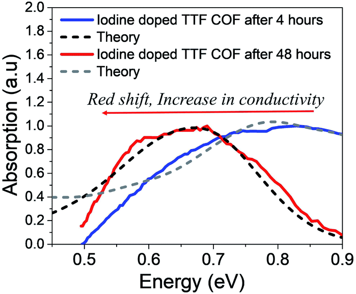 | ||
| Fig. 5 Comparison of the simulated IR spectrum (dashed) to the measured spectrum of iodine doped TTF-COFs at two different time intervals. Replotted and normalized from ref. 47. | ||
In all our comparisons with the available experimental data, we have considered 3D tetragonal lattices. COF topologies vary across different structures. For example, 2D TANG COF is a superposition of Kagome and honeycomb lattices while WBDT COF exhibits a dual pore Kagome structure. Investigating the impact of topology on charge transport is beyond the scope of this current study and will be addressed in future. However, the general conclusions for iodine doped COFs will remain unchanged as schematically demonstrated in Fig. S7.† Further development of the model, i.e., incorporating off-diagonal disorder in our study may provide a better quantitative fit to experimental data.
5 Conclusion and outlook
To summarize, we have provided a comprehensive and detailed understanding of the microscopic structure–property relationships and charge transport physics of 2D COFs. A robust theoretical model was developed which quantitatively describes the mid-IR line shape for chemically induced polarons in COFs and explains the origin of the two main bands in the absorption spectrum. Based on our discussions, we have shown that the low energy spectral signatures, in particular, the position of peak B and the A/B peak ratio can be effectively used to extract fundamental information about the disorder induced local structural arrangement within the frameworks, location of the dopant counter-anions in the COF matrix, and the extent of intra- and inter-framework polaron delocalization. Spectral signatures are identified which attributes lower conductivity in iodine doped COFs to strong Coulomb binding, lack of inter-domain charge transport, and the presence of high defect density in the 2D-layers. In order to address these shortcomings and improve conductivity in 2D COFs, well known requirements such as extended π-conjugation, high degree of crystallinity, long range ordered domains, and efficient overlap of the electronic wavefunctions between the 2D-layers need to be met. However, in the case doped COF films, key new research directions would involve an in-depth analysis of the mid-IR spectral changes as a function of linker lengths, type of linkers, pore sizes, topology, dopant type, and dopant concentrations. Time dependant as well as dopant concentration dependant FTIR measurements of doped COF films will provide a better understanding of the dopant–hole interactions, morphologies, and the complex disordered landscape of various COF structures. While iodine doping have resulted in increased conductivities by several orders of magnitude, the conductivities are unstable and reversible. Therefore, in order to achieve permanent, stable and meaningful increase in conductivity for potential device applications, dopants which do not infiltrate the frameworks and maximize localization effects are crucial. Bulky p-dopants (F4TCNQ, DDB-F72) and dopants having high electron affinity64,96 can be used in conjunction with electroactive building blocks to improve final device performance. The importance of electroactive building blocks was pointed out in ref. 50 where the authors showed that using benzodithiophene as a linker resulted in more efficient doping compared to terephthalaldehyde.In the absence of chemical dopants, “free” holes can be generated either by photoinduced absorption spectroscopy or charge modulation spectroscopy (CMS).31,34,39,62,97 Creation of free holes generally yields higher mobility since their movement is not restricted by dopant counter-anions. Low energy polaron signals have been used to characterize the local structural order, chain alignment, morphology and crystallinity of conjugated polymers in the vicinity of the charge carriers.33,97 CMS measurements on high molecular weight 100% RR-P3HT showed much higher charge carrier mobilities and a A/B peak ratio of ≈1.7.34 An even higher A/B ratio (≈2.0) was reported in photoinduced IR spectra of donor–acceptor polymer PCPDTBT blends with electron acceptor PCBM, although the mobilities were not reported.33 CMS measurements on various COF structures can reveal critical insights into the structure–property relationships and factors affecting hole movement in the frameworks.
While unpolarized mid-IR measurements are crucial, polarized measurements on oriented COF films, although experimentally challenging, can be a significant step forward in advancing our fundamental understanding of polaron photophysics and transport signatures of 2D COFs (see Section 5 in ESI†). To unambiguously understand the anisotropic nature of hole coherence in doped COF films, more experiments need to be conducted on aligned (doped and undoped) COF samples. From a theoretical standpoint, important future directions would be focused on investigating the effect of topology on charge transport and the effect of various dopants on the electronic band structure of prototypical COF structures. We hope that our detailed theoretical investigation will not only bridge the gap between the COFs and polymer communities but also motivate future exciting experiments along the same lines which might pave the way for better COF/polymer-based devices for a wide range of optoelectronics applications.
Author contributions
RG and FP: designed project and wrote the manuscript. RG performed research and analyzed the results. FP: supervised the project.Conflicts of interest
There are no conflicts to declare.Acknowledgements
This research was supported by the National Science Foundation through grant no. 1704063. This research used resources of the National Energy Research Scientific Computing Center (NERSC), which is supported by the Office of Science of the U.S. Department of Energy under Contract DE-AC02-05CH11231, as well as the Triton Shared Computing Cluster (TSCC) at the San Diego Supercomputer Center (SDSC). The softwares PETSc and SLEPc were used to diagonalize the Hamiltonian.98–100Notes and references
- A. P. Cote, A. I. Benin, N. W. Ockwig, M. O'Keeffe, A. J. Matzger and O. M. Yaghi, Science, 2005, 310, 1166–1170 CrossRef CAS PubMed.
- F. J. Uribe-Romo, J. R. Hunt, H. Furukawa, C. Klock, M. O'Keeffe and O. M. Yaghi, J. Am. Chem. Soc., 2009, 131, 4570–4571 CrossRef CAS PubMed.
- F. J. Uribe-Romo, C. J. Doonan, H. Furukawa, K. Oisaki and O. M. Yaghi, J. Am. Chem. Soc., 2011, 133, 11478–11481 CrossRef CAS PubMed.
- S. Kandambeth, K. Dey and R. Banerjee, J. Am. Chem. Soc., 2018, 141, 1807–1822 CrossRef PubMed.
- K. Dey, S. Bhunia, H. S. Sasmal, C. M. Reddy and R. Banerjee, J. Am. Chem. Soc., 2021, 143, 955–963 CrossRef CAS PubMed.
- J. L. Segura, M. J. Mancheño and F. Zamora, Chem. Soc. Rev., 2016, 45, 5635–5671 RSC.
- M. S. Lohse and T. Bein, Adv. Funct. Mater., 2018, 28, 1705553 CrossRef.
- L. Xu, S.-Y. Ding, J. Liu, J. Sun, W. Wang and Q.-Y. Zheng, Chem. Commun., 2016, 52, 4706–4709 RSC.
- H. M. El-Kaderi, J. R. Hunt, J. L. Mendoza-Cortés, A. P. Côté, R. E. Taylor, M. O'Keeffe and O. M. Yaghi, Science, 2007, 316, 268–272 CrossRef CAS PubMed.
- H. Furukawa and O. M. Yaghi, J. Am. Chem. Soc., 2009, 131, 8875–8883 CrossRef CAS PubMed.
- E. Jin, M. Asada, Q. Xu, S. Dalapati, M. A. Addicoat, M. A. Brady, H. Xu, T. Nakamura, T. Heine and Q. Chen, et al. , Science, 2017, 357, 673–676 CrossRef CAS PubMed.
- G. H. Bertrand, V. K. Michaelis, T.-C. Ong, R. G. Griffin and M. Dincă, Proc. Natl. Acad. Sci. U.S.A., 2013, 110, 4923–4928 CrossRef CAS PubMed.
- J. W. Colson, A. R. Woll, A. Mukherjee, M. P. Levendorf, E. L. Spitler, V. B. Shields, M. G. Spencer, J. Park and W. R. Dichtel, Science, 2011, 332, 228–231 CrossRef CAS PubMed.
- A. M. Evans, L. R. Parent, N. C. Flanders, R. P. Bisbey, E. Vitaku, M. S. Kirschner, R. D. Schaller, L. X. Chen, N. C. Gianneschi and W. R. Dichtel, Science, 2018, 361, 52–57 CrossRef CAS PubMed.
- N. C. Flanders, M. S. Kirschner, P. Kim, T. J. Fauvell, A. M. Evans, W. Helweh, A. P. Spencer, R. D. Schaller, W. R. Dichtel and L. X. Chen, J. Am. Chem. Soc., 2020, 142, 14957–14965 CrossRef CAS PubMed.
- X. Chen, M. Addicoat, S. Irle, A. Nagai and D. Jiang, J. Am. Chem. Soc., 2013, 135, 546–549 CrossRef CAS PubMed.
- W. K. Haug, E. M. Moscarello, E. R. Wolfson and P. L. McGrier, Chem. Soc. Rev., 2020, 49, 839–864 RSC.
- A. C. Jakowetz, T. F. Hinrichsen, L. Ascherl, T. Sick, M. Calik, F. Auras, D. D. Medina, R. H. Friend, A. Rao and T. Bein, J. Am. Chem. Soc., 2019, 141, 11565–11571 CrossRef CAS PubMed.
- L. Ascherl, E. W. Evans, J. Gorman, S. Orsborne, D. Bessinger, T. Bein, R. H. Friend and F. Auras, J. Am. Chem. Soc., 2019, 141, 15693–15699 CrossRef CAS PubMed.
- R. L. Li, N. C. Flanders, A. M. Evans, W. Ji, I. Castano, L. X. Chen, N. C. Gianneschi and W. R. Dichtel, Chem. Sci., 2019, 10, 3796–3801 RSC.
- D. W. Burke, C. Sun, I. Castano, N. C. Flanders, A. M. Evans, E. Vitaku, D. C. McLeod, R. H. Lambeth, L. X. Chen and N. C. Gianneschi, et al. , Angew. Chem., Int. Ed., 2020, 59, 5165–5171 CrossRef CAS PubMed.
- S. Xu, H. Sun, M. Addicoat, B. P. Biswal, F. He, S. Park, S. Paasch, T. Zhang, W. Sheng and E. Brunner, et al. , Adv. Mater., 2021, 33, 2006274 CrossRef CAS PubMed.
- X. Zhuang, W. Zhao, F. Zhang, Y. Cao, F. Liu, S. Bi and X. Feng, Polym. Chem., 2016, 7, 4176–4181 RSC.
- D. L. Pastoetter, S. Xu, M. Borrelli, M. Addicoat, B. P. Biswal, S. Paasch, A. Dianat, H. Thomas, R. Berger and S. Reineke, et al. , Angew. Chem., Int. Ed., 2020, 59, 23620–23625 CrossRef CAS PubMed.
- S. Xu, M. Richter and X. Feng, Acc. Mater. Res., 2021, 2(4), 252–265 CrossRef CAS.
- R. Liu, K. T. Tan, Y. Gong, Y. Chen, Z. Li, S. Xie, T. He, Z. Lu, H. Yang and D. Jiang, Chem. Soc. Rev., 2021, 50, 120–242 RSC.
- C. Kang, Z. Zhang, V. Wee, A. K. Usadi, D. C. Calabro, L. S. Baugh, S. Wang, Y. Wang and D. Zhao, J. Am. Chem. Soc., 2020, 142, 12995–13002 CrossRef CAS PubMed.
- X. Li, J. Qiao, S. W. Chee, H.-S. Xu, X. Zhao, H. S. Choi, W. Yu, S. Y. Quek, U. Mirsaidov and K. P. Loh, J. Am. Chem. Soc., 2020, 142, 4932–4943 CrossRef CAS PubMed.
- M. Wang, M. Wang, H.-H. Lin, M. Ballabio, H. Zhong, M. Bonn, S. Zhou, T. Heine, E. Cánovas and R. Dong, et al. , J. Am. Chem. Soc., 2020, 142(52), 21622–21627 CrossRef CAS PubMed.
- S. Xu, Y. Li, B. P. Biswal, M. A. Addicoat, S. Paasch, P. Imbrasas, S. Park, H. Shi, E. Brunner and M. Richter, et al. , Chem. Mater., 2020, 32, 7985–7991 CrossRef CAS.
- H. Sirringhaus, P. Brown, R. Friend, M. M. Nielsen, K. Bechgaard, B. Langeveld-Voss, A. Spiering, R. A. Janssen, E. Meijer and P. Herwig, et al. , Nature, 1999, 401, 685–688 CrossRef CAS.
- R. Österbacka, C. P. An, X. Jiang and Z. V. Vardeny, Science, 2000, 287, 839–842 CrossRef PubMed.
- S. Kahmann, M. A. Loi and C. J. Brabec, J. Mater. Chem. C, 2018, 6, 6008–6013 RSC.
- A. R. Chew, R. Ghosh, V. Pakhnyuk, J. Onorato, E. C. Davidson, R. A. Segalman, C. K. Luscombe, F. C. Spano and A. Salleo, Adv. Funct. Mater., 2018, 28, 1804142 CrossRef.
- R. Ghosh and F. C. Spano, Acc. Chem. Res., 2020, 53, 2201–2211 CrossRef CAS PubMed.
- M. G. Voss, D. T. Scholes, J. R. Challa and B. J. Schwartz, Faraday Discuss., 2019, 216, 339–362 RSC.
- V. Lakshmi, C.-H. Liu, M. Rajeswara Rao, Y. Chen, Y. Fang, A. Dadvand, E. Hamzehpoor, Y. Sakai-Otsuka, R. S. Stein and D. F. Perepichka, J. Am. Chem. Soc., 2020, 142, 2155–2160 CrossRef CAS PubMed.
- X. M. Jiang, R. Österbacka, O. Korovyanko, C. P. An, B. Horovitz, R. A. Janssen and Z. V. Vardeny, Adv. Funct. Mater., 2002, 12, 587–597 CrossRef CAS.
- J.-F. Chang, J. Clark, N. Zhao, H. Sirringhaus, D. W. Breiby, J. W. Andreasen, M. M. Nielsen, M. Giles, M. Heeney and I. McCulloch, Phys. Rev. B, 2006, 74, 115318 CrossRef.
- P. J. Brown, D. S. Thomas, A. Köhler, J. S. Wilson, J.-S. Kim, C. M. Ramsdale, H. Sirringhaus and R. H. Friend, Phys. Rev. B, 2003, 67, 064203 CrossRef.
- T. J. Aubry, J. C. Axtell, V. M. Basile, K. Winchell, J. R. Lindemuth, T. M. Porter, J.-Y. Liu, A. N. Alexandrova, C. P. Kubiak and S. H. Tolbert, et al. , Adv. Mater., 2019, 31, 1805647 CrossRef PubMed.
- C. Enengl, S. Enengl, S. Pluczyk, M. Havlicek, M. Lapkowski, H. Neugebauer and E. Ehrenfreund, Chemphyschem, 2016, 17, 3836–3844 CrossRef CAS PubMed.
- H. Yu and D. Wang, J. Am. Chem. Soc., 2020, 142, 11013–11021 CrossRef CAS PubMed.
- Z. Meng, R. M. Stolz and K. A. Mirica, J. Am. Chem. Soc., 2019, 141, 11929–11937 CrossRef CAS PubMed.
- C. Wang, Y. Wang, R. Ge, X. Song, X. Xing, Q. Jiang, H. Lu, C. Hao, X. Guo and Y. Gao, et al. , Chem. - Eur. J., 2018, 24, 585–589 CrossRef CAS PubMed.
- L. Wang, B. Dong, R. Ge, F. Jiang and J. Xu, ACS Appl. Mater. Interfaces, 2017, 9, 7108–7114 CrossRef CAS PubMed.
- S.-L. Cai, Y.-B. Zhang, A. B. Pun, B. He, J. Yang, F. M. Toma, I. D. Sharp, O. M. Yaghi, J. Fan and S.-R. Zheng, et al. , Chem. Sci., 2014, 5, 4693–4700 RSC.
- S. Jin, T. Sakurai, T. Kowalczyk, S. Dalapati, F. Xu, H. Wei, X. Chen, J. Gao, S. Seki and S. Irle, et al. , Chem. - Eur. J., 2014, 20, 14608–14613 CrossRef CAS PubMed.
- H. Li, J. Chang, S. Li, X. Guan, D. Li, C. Li, L. Tang, M. Xue, Y. Yan and V. Valtchev, et al. , J. Am. Chem. Soc., 2019, 141, 13324–13329 CrossRef CAS PubMed.
- J. M. Rotter, R. Guntermann, M. Auth, A. Mähringer, A. Sperlich, V. Dyakonov, D. D. Medina and T. Bein, Chem. Sci., 2020, 11, 12843–12853 RSC.
- D. D. Medina, M. L. Petrus, A. N. Jumabekov, J. T. Margraf, S. Weinberger, J. M. Rotter, T. Clark and T. Bein, ACS Nano, 2017, 11, 2706–2713 CrossRef CAS PubMed.
- H. Qi, H. Sahabudeen, B. Liang, M. Položij, M. A. Addicoat, T. E. Gorelik, M. Hambsch, M. Mundszinger, S. Park and B. V. Lotsch, et al. , Sci. Adv., 2020, 6, eabb5976 CrossRef CAS PubMed.
- I. Castano, A. M. Evans, R. d. Reis, V. P. Dravid, N. C. Gianneschi and W. R. Dichtel, Chem. Mater., 2021, 33(4), 1341–1352 CrossRef CAS.
- M. Luo, Q. Yang, W. Yang, J. Wang, F. He, K. Liu, H. Cao and H. Yan, Small, 2020, 16, 2001100 CrossRef CAS PubMed.
- A. M. Pütz, M. W. Terban, S. Bette, F. Haase, R. E. Dinnebier and B. V. Lotsch, Chem. Sci., 2020, 11, 12647–12654 RSC.
- V. Nguyen and M. Grünwald, J. Am. Chem. Soc., 2018, 140, 3306–3311 CrossRef CAS PubMed.
- H. Tanaka, A. Wakamatsu, M. Kondo, S. Kawamura, S.-i. Kuroda, Y. Shimoi, W.-T. Park, Y.-Y. Noh and T. Takenobu, Commun. Phys., 2019, 2, 1–10 CAS.
- R. Ghosh, C. M. Pochas and F. C. Spano, J. Phys. Chem. C, 2016, 120, 11394–11406 CrossRef CAS.
- R. Ghosh, A. R. Chew, J. Onorato, V. Pakhnyuk, C. K. Luscombe, A. Salleo and F. C. Spano, J. Phys. Chem. C, 2018, 122, 18048–18060 CrossRef CAS.
- R. Ghosh, C. K. Luscombe, M. Hambsch, S. C. Mannsfeld, A. Salleo and F. C. Spano, Chem. Mater., 2019, 31, 7033–7045 CrossRef CAS.
- D. T. Scholes, P. Y. Yee, J. R. Lindemuth, H. Kang, J. Onorato, R. Ghosh, C. K. Luscombe, F. C. Spano, S. H. Tolbert and B. J. Schwartz, Adv. Funct. Mater., 2017, 27, 1702654 CrossRef.
- A. R. Chew, R. Ghosh, Z. Shang, F. C. Spano and A. Salleo, J. Phys. Chem. Lett., 2017, 8, 4974–4980 CrossRef CAS PubMed.
- P. A. Finn, I. E. Jacobs, J. Armitage, R. Wu, B. D. Paulsen, M. Freeley, M. Palma, J. Rivnay, H. Sirringhaus and C. B. Nielsen, J. Mater. Chem. C, 2020, 8, 16216–16223 RSC.
- T. J. Aubry, K. Winchell, C. Z. Salamat, V. M. Basile, J. R. Lindemuth, J. M. Stauber, J. C. Axtell, R. M. Kubena, M. D. Phan and M. J. Bird, et al. , Adv. Funct. Mater., 2020, 2001800 CrossRef CAS PubMed.
- E. M. Thomas, K. A. Peterson, A. H. Balzer, D. Rawlings, N. Stingelin, R. A. Segalman and M. L. Chabinyc, Adv. Electron. Mater., 2020, 6, 2000595 CrossRef CAS.
- C. M. Pochas and F. C. Spano, J. Chem. Phys., 2014, 140, 244902 CrossRef PubMed.
- A. I. Hofmann, R. Kroon, S. Zokaei, E. Järsvall, C. Malacrida, S. Ludwigs, T. Biskup and C. Müller, Adv. Electron. Mater., 2020, 2000249 CrossRef CAS.
- H. Sahabudeen, H. Qi, M. Ballabio, M. Položij, S. Olthof, R. Shivhare, Y. Jing, S. Park, K. Liu and T. Zhang, et al. , Angew. Chem., Int. Ed., 2020, 59, 6028–6036 CrossRef CAS PubMed.
- K. Liu, H. Qi, R. Dong, R. Shivhare, M. Addicoat, T. Zhang, H. Sahabudeen, T. Heine, S. Mannsfeld and U. Kaiser, et al. , Nat. Chem., 2019, 11, 994–1000 CrossRef CAS PubMed.
- F. Haase and B. V. Lotsch, Chem. Soc. Rev., 2020, 49, 8469–8500 RSC.
- F. Auras, L. Ascherl, A. H. Hakimioun, J. T. Margraf, F. C. Hanusch, S. Reuter, D. Bessinger, M. Döblinger, C. Hettstedt and K. Karaghiosoff, et al. , J. Am. Chem. Soc., 2016, 138, 16703–16710 CrossRef CAS PubMed.
- N. J. Hestand and F. C. Spano, J. Chem. Phys., 2015, 143, 244707 CrossRef PubMed.
- N. J. Hestand and F. C. Spano, Acc. Chem. Res., 2017, 50, 341–350 CrossRef CAS PubMed.
- N. J. Hestand and F. C. Spano, Chem. Rev., 2018, 118, 7069–7163 CrossRef CAS PubMed.
- F. C. Spano, Acc. Chem. Res., 2010, 43, 429–439 CrossRef CAS PubMed.
- F. C. Spano, Annu. Rev. Phys. Chem., 2006, 57, 217–243 CrossRef CAS PubMed.
- N. Kim, S. Kee, S. H. Lee, B. H. Lee, Y. H. Kahng, Y.-R. Jo, B.-J. Kim and K. Lee, Adv. Mater., 2014, 26, 2268–2272 CrossRef CAS PubMed.
- H. Shirakawa, E. J. Louis, A. G. MacDiarmid, C. K. Chiang and A. J. Heeger, J. Chem. Soc., Chem. Commun., 1977, 578–580 RSC.
- R. Noriega, J. Rivnay, K. Vandewal, F. P. Koch, N. Stingelin, P. Smith, M. F. Toney and A. Salleo, Nat. Mater., 2013, 12, 1038–1044 CrossRef CAS PubMed.
- S. Fratini, M. Nikolka, A. Salleo, G. Schweicher and H. Sirringhaus, Nat. Mater., 2020, 19, 491–502 CrossRef CAS.
- K. Gu, C. R. Snyder, J. Onorato, C. K. Luscombe, A. W. Bosse and Y.-L. Loo, ACS Macro Lett., 2018, 7, 1333–1338 CrossRef CAS.
- V. S. Vyas, F. Haase, L. Stegbauer, G. Savasci, F. Podjaski, C. Ochsenfeld and B. V. Lotsch, Nat. Commun., 2015, 6, 1–9 Search PubMed.
- F. Haase, T. Banerjee, G. Savasci, C. Ochsenfeld and B. V. Lotsch, Faraday Discuss., 2017, 201, 247–264 RSC.
- A. F. El-Mahdy, C.-H. Kuo, A. Alshehri, C. Young, Y. Yamauchi, J. Kim and S.-W. Kuo, J. Mater. Chem. A, 2018, 6, 19532–19541 RSC.
- R. W. Tilford, S. J. Mugavero III, P. J. Pellechia and J. J. Lavigne, Adv. Mater., 2008, 20, 2741–2746 CrossRef CAS PubMed.
- L. M. Lanni, R. W. Tilford, M. Bharathy and J. J. Lavigne, J. Am. Chem. Soc., 2011, 133, 13975–13983 CrossRef CAS PubMed.
- C. M. Thompson, G. Occhialini, G. T. McCandless, S. B. Alahakoon, V. Cameron, S. O. Nielsen and R. A. Smaldone, J. Am. Chem. Soc., 2017, 139, 10506–10513 CrossRef CAS PubMed.
- N. Keller, D. Bessinger, S. Reuter, M. Calik, L. Ascherl, F. C. Hanusch, F. Auras and T. Bein, J. Am. Chem. Soc., 2017, 139, 8194–8199 CrossRef CAS PubMed.
- H.-Q. Yin, F. Yin and X.-B. Yin, Chem. Sci., 2019, 10, 11103–11109 RSC.
- P. Albacete, J. I. Martinez, X. Li, A. Lopez-Moreno, S. Mena-Hernando, A. E. Platero-Prats, C. Montoro, K. P. Loh, E. M. Perez and F. Zamora, J. Am. Chem. Soc., 2018, 140, 12922–12929 CrossRef CAS PubMed.
- X. Wu, X. Han, Y. Liu, Y. Liu and Y. Cui, J. Am. Chem. Soc., 2018, 140, 16124–16133 CrossRef CAS PubMed.
- A. Halder, M. Ghosh, A. Khayum M, S. Bera, M. Addicoat, H. S. Sasmal, S. Karak, S. Kurungot and R. Banerjee, J. Am. Chem. Soc., 2018, 140, 10941–10945 CrossRef CAS PubMed.
- A. Halder, S. Karak, M. Addicoat, S. Bera, A. Chakraborty, S. H. Kunjattu, P. Pachfule, T. Heine and R. Banerjee, Angew. Chem., Int. Ed., 2018, 57, 5797–5802 CrossRef CAS PubMed.
- X. Li, Q. Gao, J. Wang, Y. Chen, Z.-H. Chen, H.-S. Xu, W. Tang, K. Leng, G.-H. Ning and J. Wu, et al. , Nat. Commun., 2018, 9, 1–9 CrossRef PubMed.
- S. B. Alahakoon, K. Tan, H. Pandey, S. D. Diwakara, G. T. McCandless, D. I. Grinffiel, A. Durand-Silva, T. Thonhauser and R. A. Smaldone, J. Am. Chem. Soc., 2020, 142, 12987–12994 CrossRef CAS PubMed.
- J. Saska, G. Gonel, Z. I. Bedolla-Valdez, S. D. Aronow, N. E. Shevchenko, A. S. Dudnik, A. J. Moulé and M. Mascal, Chem. Mater., 2019, 31, 1500–1506 CrossRef CAS.
- S. Kahmann, D. Fazzi, G. J. Matt, W. Thiel, M. A. Loi and C. J. Brabec, J. Phys. Chem. Lett., 2016, 7, 4438–4444 CrossRef CAS PubMed.
- V. Hernandez, J. E. Roman and V. Vidal, ACM Trans. Math Software, 2005, 31, 351–362 CrossRef.
- J. E. Roman, C. Campos, E. Romero and A. Tomas, SLEPc Users Manual, D. Sistemes Informàtics i Computació, Universitat Politècnica de València, Technical Report DSIC-II/24/02 - Revision 3.14, 2020 Search PubMed.
- S. Balay, S. Abhyankar, M. F. Adams, J. Brown, P. Brune, K. Buschelman, L. Dalcin, A. Dener, V. Eijkhout, W. D. Gropp, D. Karpeyev, D. Kaushik, M. G. Knepley, D. A. May, L. C. McInnes, R. T. Mills, T. Munson, K. Rupp, P. Sanan, B. F. Smith, S. Zampini, H. Zhang and H. Zhang, PETSc Web page, 2019, https://www.mcs.anl.gov/petsc Search PubMed.
Footnote |
| † Electronic supplementary information (ESI) available: The 3D Holstein Hamiltonian for tetragonal COF structures is given. The expressions for IR absorption spectrum and coherence function along with a brief explanation of the fundamental nature and origin of the two bands A and B are discussed. Parameters used to define the Hamiltonian for the figures in the main text are provided. See DOI: 10.1039/d1sc01262b |
| This journal is © The Royal Society of Chemistry 2021 |