 Open Access Article
DNA-based constitutional dynamic networks as functional modules for logic gates and computing circuit operations†
Zhixin
Zhou
 a,
Jianbang
Wang
a,
R. D.
Levine
a,
Francoise
Remacle
b and
Itamar
Willner
a,
Jianbang
Wang
a,
R. D.
Levine
a,
Francoise
Remacle
b and
Itamar
Willner
 *a
*a
aThe Institute of Chemistry, The Hebrew University of Jerusalem, Jerusalem 91904, Israel. E-mail: Itamar.willner@mail.huji.ac.il
bTheoretical Physical Chemistry, UR MolSys B6c, University of Liège, B4000 Liège, Belgium
First published on 17th March 2021
Abstract
A nucleic acid-based constitutional dynamic network (CDN) is introduced as a single computational module that, in the presence of different sets of inputs, operates a variety of logic gates including a half adder, 2![[thin space (1/6-em)]](https://www.rsc.org/images/entities/char_2009.gif) :
:![[thin space (1/6-em)]](https://www.rsc.org/images/entities/char_2009.gif) 1 multiplexer and 1
1 multiplexer and 1![[thin space (1/6-em)]](https://www.rsc.org/images/entities/char_2009.gif) :
:![[thin space (1/6-em)]](https://www.rsc.org/images/entities/char_2009.gif) 2 demultiplexer, a ternary multiplication matrix and a cascaded logic circuit. The CDN-based computational module leads to four logically equivalent outputs for each of the logic operations. Beyond the significance of the four logically equivalent outputs in establishing reliable and robust readout signals of the computational module, each of the outputs may be fanned out, in the presence of different inputs, to a set of different logic circuits. In addition, the ability to intercommunicate constitutional dynamic networks (CDNs) and to construct DNA-based CDNs of higher complexity provides versatile means to design computing circuits of enhanced complexity.
2 demultiplexer, a ternary multiplication matrix and a cascaded logic circuit. The CDN-based computational module leads to four logically equivalent outputs for each of the logic operations. Beyond the significance of the four logically equivalent outputs in establishing reliable and robust readout signals of the computational module, each of the outputs may be fanned out, in the presence of different inputs, to a set of different logic circuits. In addition, the ability to intercommunicate constitutional dynamic networks (CDNs) and to construct DNA-based CDNs of higher complexity provides versatile means to design computing circuits of enhanced complexity.
Introduction
The use of DNA as a functional material for logic gate operations and computational circuitry has attracted substantial research efforts in the past two decades.1–4 Data storage, retrieval and random access of information by DNA strands,5–8 and the use of DNA assemblies as functional in vivo operating computing circuitry, were extensively discussed.9–11 The structural and functional information encoded in the base sequences of nucleic acids, and the possibility to reconfigure nucleic acid structures by auxiliary input triggers such as pH,12–14 metal ions,15–17 fuel strands,18,19 molecular or macromolecular ligands20,21 and DNA machines22,23 enabled the design of logic gates of variable complexities. In addition, by applying the strand displacement mechanism,24–26 the programmed cleavage of DNA templates by enzymes27,28 and the catalytic functions of nucleic acids (DNAzymes),29–32 complex nucleic acid-based computing circuitries and cascaded logic gates were demonstrated. Furthermore, the catalytic properties of nucleic acids provided powerful units as output transduction modules of logic gate cascades and computing circuitry operations.33–35 However, the processing and scaling of DNA computing systems are still challenging issues. Past efforts addressed these problems by designing reversible logic gates,36,37 switching circuits,38 continuous multivalued logic,39 multiplexer–demultiplexer systems40,41 and the construction of multilayer input–output logic gates.42–44 Also, the use of two-dimensional and three-dimensional DNA objects revealing shape complementarity or localized signal propagation could provide means to enhance computational efficacy.45–47Nucleic acid-based constitutional dynamic networks, CDNs, attract substantial research efforts as a means to mimic biological networks.48 The simplest [2 × 2] CDN consists of four two-component equilibrated constituents AA′, AB′, BA′ and BB′.49,50 The stabilization of one of the constituents, e.g., AA′, results in the adaptive reconfiguration of the CDN into a new equilibrated network where the constituent AA′ is upregulated (enriched in its content) at the expense of the constituents that share components with AA′, e.g., AB′ and BA′, that are separated to enrich AA′. The separated constituents lead to the formation of B and B′ that recombine. Thus, the upregulation of AA′ is accompanied by the downregulation of AB′ and BA′, and the concomitant upregulation of the constituent that does not share components with AA′, e.g., BB′. The base sequence comprising nucleic acid offers substantial structural and functional information that provides means to construct and operate the dynamic functions of CDNs. The stability of duplex nucleic acids is dictated by the number and nature of base pairs comprising the duplexes.51–53 In addition, the formation of DNA triplexes54 or G-quadruplexes55,56 and the intercalation of photoisomerizable intercalators into double stranded nucleic acids,57–59 provide versatile means to control the stability of DNA structures. Furthermore, functional information encoded in nucleic acid structures include catalytic properties (DNAzymes).60–62 By the conjugation of catalytic nucleic acids to the CDN constituents, catalytic readout units can be integrated into the constituent structures, and these act as transducing outputs that follow the input-driven dynamic reconfiguration transition of the CDNs. Indeed, in a series of recent reports the input-driven dynamic reconfiguration of nucleic acid-based CDNs were introduced. The adaptive reconfiguration of CDNs using fuel strands,63 guided formation of K+-ion-stabilized G-quadruplexes,64 formation of triplex structures65 and the application of photoisomerizable azobenzene modules and light66 was demonstrated. By coupling Mg2+-ion-dependent DNAzyme units, optical (fluorescence) transducing reporter outputs that follow the dynamic transitions of the CDNs were established. The nucleic acid-based CDNs were used to mimic native dynamic networks by providing the intercommunication of CDNs,65 feedback-driven CDNs,64 the assembly of networks of enhanced complexities, e.g., [3 × 3] CDNs67 and three-dimensional CDNs.68 The application of CDNs is, however, a challenging topic. CDNs were applied as functional modules to design hydrogel materials of switchable stiffness properties,69 to regulate and switch the aggregation and catalytic properties of nanoparticles,70 and to control the dimerization of DNA tetrahedra structures as models for protein–protein interactions.71 The intrinsic features of CDNs to be triggered by auxiliary input triggers and the ability to readout the state (composition) of the CDNs by catalytic DNAzyme output signals suggest the CDNs could provide a module for logic operation and the design of computing circuits.
Here we wish to introduce a single CDN module that, in the presence of appropriate auxiliary inputs, behaves like a reprogrammable logic unit that can be reconfigured to operate as a half-adder, a 2![[thin space (1/6-em)]](https://www.rsc.org/images/entities/char_2009.gif) :
:![[thin space (1/6-em)]](https://www.rsc.org/images/entities/char_2009.gif) 1 multiplexer and 1
1 multiplexer and 1![[thin space (1/6-em)]](https://www.rsc.org/images/entities/char_2009.gif) :
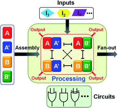
:![[thin space (1/6-em)]](https://www.rsc.org/images/entities/char_2009.gif) 2 demultiplexer, a ternary multiplication matrix and a cascaded logic circuit. The fact that the AND and XOR gates operate, in parallel, in the single CDN module of the half adder (or in the general map of CDN responses on switches acting in series or in parallel) implies that the CDNs modules provide a universal set of gates. Namely, any Boolean function (of two variables) can be computed with the same CDN module using different triggers as inputs. Besides demonstrating the versatility of logic gates and computing circuits, the use of CDNs as computing module introduces a unique feature reflected by the transduction of each of the operating gates by four parallel output signals provided by the four constituents. This redundant output represents a significant robustness, reliability and accuracy of the readout outputs. Furthermore, the four parallel outputs may be utilized to fan-out the information generated by the computation module to form diverse computing circuits outlined in Scheme 1.
2 demultiplexer, a ternary multiplication matrix and a cascaded logic circuit. The fact that the AND and XOR gates operate, in parallel, in the single CDN module of the half adder (or in the general map of CDN responses on switches acting in series or in parallel) implies that the CDNs modules provide a universal set of gates. Namely, any Boolean function (of two variables) can be computed with the same CDN module using different triggers as inputs. Besides demonstrating the versatility of logic gates and computing circuits, the use of CDNs as computing module introduces a unique feature reflected by the transduction of each of the operating gates by four parallel output signals provided by the four constituents. This redundant output represents a significant robustness, reliability and accuracy of the readout outputs. Furthermore, the four parallel outputs may be utilized to fan-out the information generated by the computation module to form diverse computing circuits outlined in Scheme 1.
Results and discussion
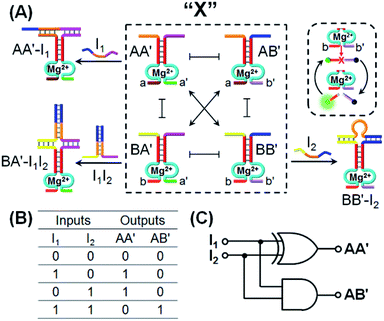
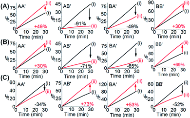
One CDN-based logic gate system operating as a half-adder is displayed in Fig. 1. It consists of CDN “X” that is composed of the four constituents AA′, AB′, BA′ and BB′. Each of the constituents includes duplex domains conjugated to single strand loops in each of the components. To the loop strands are associated with single strand tethers, a, a′, b, and b′, that yield “arms”, a/a′, a/b′, b/a′ and b/b′ conjugated to the constituents AA′, AB′, BA′ and BB′, respectively. In addition, the components of the duplex domains associated with the four constituents are further conjugated to single strand tethers that allow further dictated hybridization with auxiliary strands. The double-loop domains extended by the respective arms a/a′, a/b′, b/a′ and b/b′ form the Mg2+-ion-dependent DNAzyme assemblies that can recognize four different fluorophore (Fi)-/quencher (Qi)-functionalized substrates (Si). The cleavage of these substrates leads to the triggered formation of the respective fluorescence, Fi. By following the time-dependent fluorescence changes of each of the fluorophores, and using appropriate calibration curves generated by different concentrations of the intact, separate constituents, the contents of the each of constituents in CDN “X” could be quantitatively evaluated. The contents of the constituents in the equilibrated CDN “X” are controlled by the relative stabilities of the constituents. The operation of the CDN “X” as a logic gate module is displayed in Fig. 1A by subjecting the CDN to the strands I1 or/and I2 as inputs. Treatment of the CDN “X” with input I1 results in its hybridization to the arms of AA′. The stabilization of the constituents (AA′–I1) reconfigures the CDN by the upregulation of AA′, the concomitant upregulation of BB′ and the downregulation of AB′ and BA′. Subjecting the CDN “X” to the input I2 leads to the stabilization of the constituent BB′ in the form of BB′–I2, and thus reconfigures the CDN into a new equilibrated configuration where BB′ is upregulated with the concomitant upregulation of AA′, and the downregulation of the constituents AB′ and BA′. The two triggered inputs I1 and I2 are, however, pre-engineered to interhybridize into a duplex structure that includes two single-stranded arms capable of hybridizing with the free arms associated with the constituent BA′. Thus, subjecting the CDN “X” to the two inputs I1 and I2 results in the hybridization of duplex I1I2 to the constituent BA′. The association and stabilization of constituent BA′ in the form of BA′–I1I2 reconfigures the CDN into a newly equilibrated configuration where BA′–I1I2 is upregulated with the concomitant upregulation of AB′ and the downregulation of AA′ and BB′. The contents of the constituents in the input-triggered reconfigured CDNs provide, then, the output readout signals of the systems. For example, Fig. 1B exemplifies the expected truth table upon the inputs I1/I2-driven reconfiguration of the CDN and using the contents of AA′ and AB′ as output signals for the system (as compared to the original contents of the constituents). Considering the initial contents of AA′ and AB′ in CDN “X” as zero base labels of the outputs and any increased value of these outputs as a true output “1”, the truth table demonstrates that in the presence of the input I1 or I2, the output AB′ corresponds to an “AND” gate whereas the output of AA′ corresponds to a “XOR” gate. Thus, the inputs I1/I2-driven reconfiguration of the CDN “X” module yields a half-adder operation, as schematically presented in Fig. 1C.In fact, the I1/I2-driven reconfiguration of CDN “X” yields four logically equivalent pairs of output signals (vide infra). Nonetheless, as will be point out, the redundancy of the logically equivalent pairs of outputs introduced reliable readout of the computing module, and each of the equivalent outputs may be fanned out to a different logic circuit by coupling to different inputs. The experimental results demonstrating the parallel operation of the CDN as a functional half-adder system are presented in Fig. 2. Fig. 2A shows the time-dependent fluorescence changes generated by the Mg2+-ion-DNAzyme reporter units associated with the constituents of CDN “X” before subjecting the system to input I1, curves (i), and after the equilibration of the CDN in the presence of input I1, curves (ii). As expected, the fluorescence changes generated by the reporter units linked to AA′ and BB′ are upregulated by (49% and 30%, respectively) whereas the fluorescence changes of the reporter units conjugated to AB′ and BA′ are downregulated (by 91% and 49%). Similarly, Fig. 2B depicts the time-dependent fluorescence changes generated by the reporter units associated with CDN “X” before (curves (i)) and after (curves (ii)) the treatment of the CDN “X” with input I2. As explained, the fluorescence changes generated by the reporter units linked to AA′ and BB′ are enhanced by 30% and 69%, while the fluorescence outputs of AB′ and BA′ are downregulated by 71% and 65%, respectively. Fig. 2C shows the fluorescence changes transduced by the reporter units linked to the constituents upon reequilibration of the CDN, in the presence of the two inputs I1 and I2. Under these conditions, the time-dependent fluorescence changes generated by the reporter units associated with the constituents reveal the downregulation of AA′ (34%) and BB′ (52%), as compared to the fluorescence intensities of these reporter units prior to the intervention with the inputs. In turn, the I1I2-driven downregulation of the fluorescence intensities of AA′ and BB′, is accompanied, as expected, by the concomitant upregulation of the fluorescence intensities of AB′ and BA′ by 73% and 53%, respectively. The time-dependent fluorescence changes generated by the Mg2+-ion-dependent DNAzyme reporter units before treatment of CDN “X” with the inputs, and after subjecting of the CDN to the respective inputs were translated into the quantitative contents of the constituents. For this purpose, appropriate calibration curves relating to the fluorescence changes generated by variable concentrations of intact, separated, constituents were derived, Fig. S1 and S2.† The contents of the constituents in the different states of the CDN are summarized in Fig. S3.† (For the sensitivity of the reporter units to concentration changes of the input, and thus to possible errors of the computational module see Fig. S4† and accompanying discussion). Furthermore, it should be noted that the degrees of upregulation and downregulation of the four constituents differ in their magnitudes. This is consistent with the fact that the constituents in their initial states differ in their equilibrated concentrations and these values are dictated by the relative stabilities of the constituents. The degrees of upregulation/downregulation are, also, determined by the relative stabilities of the constituents.
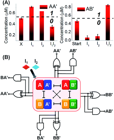
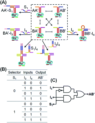
Fig. 3A depicts the concentrations of the AA′ and AB′ in the presence of a “bar” presentation. Using the contents of the constituents in CDN “X” as a threshold value to evaluate the output signals, one may realize that the output of AA′ corresponds to a XOR gate, while the output of AB′ corresponds to an “AND” gate, and the two outputs of the CDN yield the parallel half-adder operation. (For further support on the parallel readout of the half-adder operation by electrophoretic measurements, see Fig. S5† and accompanying discussion). The discussion has exemplified the parallel half-adder operation of the CDN by applying the responses of AA′ and AB′ as outputs of the half-adder. Nonetheless, by using the readout signals of the other constituents of the CDN as outputs, one may formulate the truth table shown in Fig. S3A,† demonstrating that the I1/I2-driven operation of the CDN yields the parallel generation of four pairs of logically equivalent output signals for the same half-adder Fig. 3B. These results demonstrate the unique and important features of CDNs for operating logic gate circuitry. The CDN “X” does not only provide an integrated module for the operation of a half-adder, but introduces a functional unit that yields four logically equivalent pairs of output signals for a single half-adder. In addition, this result is not only important as a path to reduce the error of the circuit output, but it introduces a means to fan out the CDN to four subsequent cascaded CDNs, Fig. S3B.†
In the next step, we applied CDN “X” that previously used as the functional module to drive, in the presence of appropriate inputs, a set of half-adders, to operate, in the presence of other tailored inputs, the 1![[thin space (1/6-em)]](https://www.rsc.org/images/entities/char_2009.gif) :
:![[thin space (1/6-em)]](https://www.rsc.org/images/entities/char_2009.gif) 2 multiplexer and the 2
2 multiplexer and the 2![[thin space (1/6-em)]](https://www.rsc.org/images/entities/char_2009.gif) :
:![[thin space (1/6-em)]](https://www.rsc.org/images/entities/char_2009.gif) 1 demultiplexer logic systems. Multiplexer/demultiplexer logic operations represent routes for data compression/decompression.40 The 2
1 demultiplexer logic systems. Multiplexer/demultiplexer logic operations represent routes for data compression/decompression.40 The 2![[thin space (1/6-em)]](https://www.rsc.org/images/entities/char_2009.gif) :
:![[thin space (1/6-em)]](https://www.rsc.org/images/entities/char_2009.gif) 1 multiplexer selects and directs, in the presence/absence of a selector, two inputs into one output. On the other hand, the 1
1 multiplexer selects and directs, in the presence/absence of a selector, two inputs into one output. On the other hand, the 1![[thin space (1/6-em)]](https://www.rsc.org/images/entities/char_2009.gif) :
:![[thin space (1/6-em)]](https://www.rsc.org/images/entities/char_2009.gif) 2 demultiplexer transforms, in the presence/absence of the selector, one input into two dictated outputs. Fig. 4A introduces the use of CDN “X” as a 2
2 demultiplexer transforms, in the presence/absence of the selector, one input into two dictated outputs. Fig. 4A introduces the use of CDN “X” as a 2![[thin space (1/6-em)]](https://www.rsc.org/images/entities/char_2009.gif) :
:![[thin space (1/6-em)]](https://www.rsc.org/images/entities/char_2009.gif) 1 multiplexer system. In the presence of the input I3 that stabilizes the constituent BA′, the constituent BA′ is upregulated, the constituents AA′ and BB′ are downregulated and the constituent AB′ is concomitantly upregulated. Subjecting the CDN “X” to input I4 leads to the stabilization and upregulation of BB′, the concomitant upregulation of AA′ and the downregulation of AB′ and BA′. The input I4 is, however, engineered to hybridize with I3 and the hybrid I3I4 stabilizes constituent BA′. As a result, in the presence of the two inputs I3I4, AB′ and BA′ are upregulated whereas AA′ and BB′ are downregulated. These reconfigurations proceed, however, in the absence of the selector S1. Treatment of the CDN “X” with the selector S1 results in the stabilization and upregulation of AA′ and BB′ and the downregulation of AB′ and BA′. In the presence of S1 and I3, two counter-acting processes take place in the CDN “X”, where S1 binds to AA′ and I3 stabilizes the orthogonal constituent BA′! As a result, the S1 and I3 have counter effects on the reconfiguration of the CDN, and in the presence of S1 and I3, no significant changes in the contents of the constituents occurs. In turn, S1 is pre-engineered to hybridize with I4, and thus subjecting the CDN to S1 and I4 results in the hybridization of the hybrid S1I4 with constituent BA′, leading to the stabilization and upregulation of BA′, the concomitant up-regulation of AB′, and the downregulation of AA′ and BB′. In addition, in the presence of S1, I3 and I4, the hybrid S1I4 will stabilize constituent BA′, and I3 will also stabilize BA′. Thus, BA′ and AB′ will be upregulated, and AA′ and BB′ will be downregulated. According to these details, subjecting CDN “X” to the inputs I3 and/or I4 and selector S1, and using the responses of the DNAzyme reporter unit associated with AB′ as output, the CDN logic module will perform a 2
1 multiplexer system. In the presence of the input I3 that stabilizes the constituent BA′, the constituent BA′ is upregulated, the constituents AA′ and BB′ are downregulated and the constituent AB′ is concomitantly upregulated. Subjecting the CDN “X” to input I4 leads to the stabilization and upregulation of BB′, the concomitant upregulation of AA′ and the downregulation of AB′ and BA′. The input I4 is, however, engineered to hybridize with I3 and the hybrid I3I4 stabilizes constituent BA′. As a result, in the presence of the two inputs I3I4, AB′ and BA′ are upregulated whereas AA′ and BB′ are downregulated. These reconfigurations proceed, however, in the absence of the selector S1. Treatment of the CDN “X” with the selector S1 results in the stabilization and upregulation of AA′ and BB′ and the downregulation of AB′ and BA′. In the presence of S1 and I3, two counter-acting processes take place in the CDN “X”, where S1 binds to AA′ and I3 stabilizes the orthogonal constituent BA′! As a result, the S1 and I3 have counter effects on the reconfiguration of the CDN, and in the presence of S1 and I3, no significant changes in the contents of the constituents occurs. In turn, S1 is pre-engineered to hybridize with I4, and thus subjecting the CDN to S1 and I4 results in the hybridization of the hybrid S1I4 with constituent BA′, leading to the stabilization and upregulation of BA′, the concomitant up-regulation of AB′, and the downregulation of AA′ and BB′. In addition, in the presence of S1, I3 and I4, the hybrid S1I4 will stabilize constituent BA′, and I3 will also stabilize BA′. Thus, BA′ and AB′ will be upregulated, and AA′ and BB′ will be downregulated. According to these details, subjecting CDN “X” to the inputs I3 and/or I4 and selector S1, and using the responses of the DNAzyme reporter unit associated with AB′ as output, the CDN logic module will perform a 2![[thin space (1/6-em)]](https://www.rsc.org/images/entities/char_2009.gif) :
:![[thin space (1/6-em)]](https://www.rsc.org/images/entities/char_2009.gif) 1 multiplexed operation as summarized in the truth table, Fig. 4B, and schematically presented in Fig. 4C. The experimental results validating the 2
1 multiplexed operation as summarized in the truth table, Fig. 4B, and schematically presented in Fig. 4C. The experimental results validating the 2![[thin space (1/6-em)]](https://www.rsc.org/images/entities/char_2009.gif) :
:![[thin space (1/6-em)]](https://www.rsc.org/images/entities/char_2009.gif) 1 logic operation using AB′ as output, are summarized in Fig. S6–S12, ESI.† The time-dependent fluorescence changes generated by the reporter associated with AB′, upon subjecting the CDN “X” to the different selector/inputs, and using the appropriate calibration curves, are translated to the contents of the output, and tabulated in the form of a bar presentation, Fig. S13,† confirming that the CDN module operates, indeed, as a 2
1 logic operation using AB′ as output, are summarized in Fig. S6–S12, ESI.† The time-dependent fluorescence changes generated by the reporter associated with AB′, upon subjecting the CDN “X” to the different selector/inputs, and using the appropriate calibration curves, are translated to the contents of the output, and tabulated in the form of a bar presentation, Fig. S13,† confirming that the CDN module operates, indeed, as a 2![[thin space (1/6-em)]](https://www.rsc.org/images/entities/char_2009.gif) :
:![[thin space (1/6-em)]](https://www.rsc.org/images/entities/char_2009.gif) 1 multiplexer. Note, however, that the CDN module includes four constituents, where each constituent could act as the output, and thus, the 2
1 multiplexer. Note, however, that the CDN module includes four constituents, where each constituent could act as the output, and thus, the 2![[thin space (1/6-em)]](https://www.rsc.org/images/entities/char_2009.gif) :
:![[thin space (1/6-em)]](https://www.rsc.org/images/entities/char_2009.gif) 1 multiplexer is read out, in parallel, by four logically redundant outputs. These results are displayed in Fig. S6–S12,† in the form of the different time-dependent fluorescence changes of the reporter units associated with the different output constituents, and in the form of a bar presentation corresponding to the contents of the output constituents. The functions of the CDN “X” as a 2
1 multiplexer is read out, in parallel, by four logically redundant outputs. These results are displayed in Fig. S6–S12,† in the form of the different time-dependent fluorescence changes of the reporter units associated with the different output constituents, and in the form of a bar presentation corresponding to the contents of the output constituents. The functions of the CDN “X” as a 2![[thin space (1/6-em)]](https://www.rsc.org/images/entities/char_2009.gif) :
:![[thin space (1/6-em)]](https://www.rsc.org/images/entities/char_2009.gif) 1 multiplexer was further supported by electrophoretic imaging, see Fig. S14† and accompanying discussion.
1 multiplexer was further supported by electrophoretic imaging, see Fig. S14† and accompanying discussion.
Similarly, the CDN “X” was applied as a module that triggers the 1![[thin space (1/6-em)]](https://www.rsc.org/images/entities/char_2009.gif) :
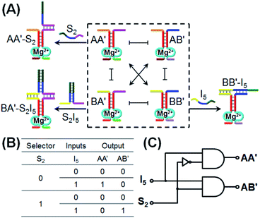
:![[thin space (1/6-em)]](https://www.rsc.org/images/entities/char_2009.gif) 2 demultiplexer logic operation, Fig. 5. This logic system transforms one input into two outputs and is exemplified with the treatment of CDN “X”, in the presence or absence of a selector S2, with input I5. The input I5 stabilizes the constituent BB′ and leads to the reconfiguration of CDN “X” into an equilibrated system where BB′ is upregulated and concomitantly AA′ is upregulated and the constituents AB′ and BA′ are downregulated. Subjecting CDN “X” to the selector S2 results in the hybridization with component A′ in constituent AA′ or BA′, but this hybridization process has no effect on the stability of AA′ and BA′, and thus, CDN “X” is not affected and none of the constituents is upregulated or downregulated. The selector S2 and input I5 are, however, pre-engineered to interhybridize to a hybrid, S2I5 that binds to the constituent BA′. Thus, subjecting CDN “X” to the selector S2 and input I5 results in the stabilization of BA′, the concomitant upregulation of AB′ and the downregulation of AA′ and BB′. Using the constituents AA′ and AB′ as outputs, the formulated truth-table in Fig. 5B follows a 1
2 demultiplexer logic operation, Fig. 5. This logic system transforms one input into two outputs and is exemplified with the treatment of CDN “X”, in the presence or absence of a selector S2, with input I5. The input I5 stabilizes the constituent BB′ and leads to the reconfiguration of CDN “X” into an equilibrated system where BB′ is upregulated and concomitantly AA′ is upregulated and the constituents AB′ and BA′ are downregulated. Subjecting CDN “X” to the selector S2 results in the hybridization with component A′ in constituent AA′ or BA′, but this hybridization process has no effect on the stability of AA′ and BA′, and thus, CDN “X” is not affected and none of the constituents is upregulated or downregulated. The selector S2 and input I5 are, however, pre-engineered to interhybridize to a hybrid, S2I5 that binds to the constituent BA′. Thus, subjecting CDN “X” to the selector S2 and input I5 results in the stabilization of BA′, the concomitant upregulation of AB′ and the downregulation of AA′ and BB′. Using the constituents AA′ and AB′ as outputs, the formulated truth-table in Fig. 5B follows a 1![[thin space (1/6-em)]](https://www.rsc.org/images/entities/char_2009.gif) :
:![[thin space (1/6-em)]](https://www.rsc.org/images/entities/char_2009.gif) 2 demultiplexer logic operation where one input I5 generated two outputs, e.g., one output of AA′ increases, in the presence of I5, while a second output of AB′ proceeds, in the presence of S2 and I5. The schematic 1
2 demultiplexer logic operation where one input I5 generated two outputs, e.g., one output of AA′ increases, in the presence of I5, while a second output of AB′ proceeds, in the presence of S2 and I5. The schematic 1![[thin space (1/6-em)]](https://www.rsc.org/images/entities/char_2009.gif) :
:![[thin space (1/6-em)]](https://www.rsc.org/images/entities/char_2009.gif) 2 demultiplexer logic is presented in Fig. 5C.
2 demultiplexer logic is presented in Fig. 5C.
The experimental results demonstrate the CDN-stimulated performance of the 1![[thin space (1/6-em)]](https://www.rsc.org/images/entities/char_2009.gif) :
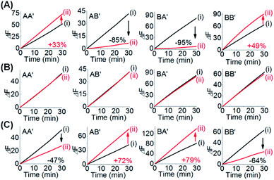
:![[thin space (1/6-em)]](https://www.rsc.org/images/entities/char_2009.gif) 2 demultiplexer are presented in Fig. 6, where the time-dependent fluorescence changes of DNAzyme reporter units associated with the four constituents upon subjecting the CDN “X” to the different inputs, are displayed. Subjecting the CDN to input I5, Fig. 6A, results in the upregulation of the reporter units associated with AA′ (by 33%), the downregulation of AB′ and BA′ by 85% and 95% and the concomitant upregulation of BB′ (by 49%). Thus, the output of AA′, is, “1”, whereas the output of AB′ is “0”. Fig. 6B depicts the time-dependent fluorescence changes of the reporter units associated with the constituents upon subjecting the CDN to the selector S1. No significant fluorescence changes after applying the selector on the CDN is observed, implying that the outputs of AA′ and of AB′ are “0” (as well as for all other constituents), consistent with the 1
2 demultiplexer are presented in Fig. 6, where the time-dependent fluorescence changes of DNAzyme reporter units associated with the four constituents upon subjecting the CDN “X” to the different inputs, are displayed. Subjecting the CDN to input I5, Fig. 6A, results in the upregulation of the reporter units associated with AA′ (by 33%), the downregulation of AB′ and BA′ by 85% and 95% and the concomitant upregulation of BB′ (by 49%). Thus, the output of AA′, is, “1”, whereas the output of AB′ is “0”. Fig. 6B depicts the time-dependent fluorescence changes of the reporter units associated with the constituents upon subjecting the CDN to the selector S1. No significant fluorescence changes after applying the selector on the CDN is observed, implying that the outputs of AA′ and of AB′ are “0” (as well as for all other constituents), consistent with the 1![[thin space (1/6-em)]](https://www.rsc.org/images/entities/char_2009.gif) :
:![[thin space (1/6-em)]](https://www.rsc.org/images/entities/char_2009.gif) 2 demultiplexer operation. Fig. 6C shows the time-dependent fluorescence changes of all four reporter units associated with the CDN upon subjecting the CDN to the selector S2 and input I5 (the output AA′ is downregulated by 47%, output “0” whereas output AB′ is upregulated by 72%, output “1”). These outputs are consistent with the performance of CDN “X”, and AA′ and AB′ as outputs, as a logic 1
2 demultiplexer operation. Fig. 6C shows the time-dependent fluorescence changes of all four reporter units associated with the CDN upon subjecting the CDN to the selector S2 and input I5 (the output AA′ is downregulated by 47%, output “0” whereas output AB′ is upregulated by 72%, output “1”). These outputs are consistent with the performance of CDN “X”, and AA′ and AB′ as outputs, as a logic 1![[thin space (1/6-em)]](https://www.rsc.org/images/entities/char_2009.gif) :
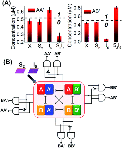
:![[thin space (1/6-em)]](https://www.rsc.org/images/entities/char_2009.gif) 2 demultiplexer. In addition, the constituent BB′ is downregulated by 64%, while the constituent BA′ is upregulated by 79%. Using the appropriate calibration curves relating the time-dependent fluorescence changes of the reporter units to different concentrations of the intact constituents, the quantitative contents of the constituents were evaluated, Fig. S15.† The contents of the constituents in the CDN “X”, in the presence of the respective input/selector, can be used for the quantitative evaluation of the output values. For example, Fig. 7A depicts in the form of a bar presentation, the use of the contents of AA′ and AB′ as constitutive outputs that follow the 1
2 demultiplexer. In addition, the constituent BB′ is downregulated by 64%, while the constituent BA′ is upregulated by 79%. Using the appropriate calibration curves relating the time-dependent fluorescence changes of the reporter units to different concentrations of the intact constituents, the quantitative contents of the constituents were evaluated, Fig. S15.† The contents of the constituents in the CDN “X”, in the presence of the respective input/selector, can be used for the quantitative evaluation of the output values. For example, Fig. 7A depicts in the form of a bar presentation, the use of the contents of AA′ and AB′ as constitutive outputs that follow the 1![[thin space (1/6-em)]](https://www.rsc.org/images/entities/char_2009.gif) :
:![[thin space (1/6-em)]](https://www.rsc.org/images/entities/char_2009.gif) 2 demultiplexer operation of the system. It should be noted that the functions of the CDN “X” as a 1
2 demultiplexer operation of the system. It should be noted that the functions of the CDN “X” as a 1![[thin space (1/6-em)]](https://www.rsc.org/images/entities/char_2009.gif) :
:![[thin space (1/6-em)]](https://www.rsc.org/images/entities/char_2009.gif) 2 demultiplexer can be followed by electrophoretic imaging of the constituents of the CDN before and after treatment with I5, S2 and S2I5 (for a detailed description of these results see Fig. S16† and accompanying discussion). In addition, we note that the operation of CDN “X” as a 1
2 demultiplexer can be followed by electrophoretic imaging of the constituents of the CDN before and after treatment with I5, S2 and S2I5 (for a detailed description of these results see Fig. S16† and accompanying discussion). In addition, we note that the operation of CDN “X” as a 1![[thin space (1/6-em)]](https://www.rsc.org/images/entities/char_2009.gif) :
:![[thin space (1/6-em)]](https://www.rsc.org/images/entities/char_2009.gif) 2 demultiplexer has applied the responses of the reporter units associated with the constituents AA′ and AB′ as outputs. The results shown in Fig. 6 indicate, however, that one can read in parallel the redundant outputs AA′/BA′, BB′/AB′ and BB′/BA′ for the 1
2 demultiplexer has applied the responses of the reporter units associated with the constituents AA′ and AB′ as outputs. The results shown in Fig. 6 indicate, however, that one can read in parallel the redundant outputs AA′/BA′, BB′/AB′ and BB′/BA′ for the 1![[thin space (1/6-em)]](https://www.rsc.org/images/entities/char_2009.gif) :
:![[thin space (1/6-em)]](https://www.rsc.org/images/entities/char_2009.gif) 2 demultiplexer system, Fig. 7B and S15.† Thus, the redundancy of the output signals of the CDN “X”-based demultiplexer system reemphasizes the possibility to fan out the demultiplexer circuit to other CDNs and thereby demonstrates the minimization of the readout error of the demultiplexer system.
2 demultiplexer system, Fig. 7B and S15.† Thus, the redundancy of the output signals of the CDN “X”-based demultiplexer system reemphasizes the possibility to fan out the demultiplexer circuit to other CDNs and thereby demonstrates the minimization of the readout error of the demultiplexer system.
Beyond the ability to use the CDN “X” as a functional module that operates half-adder, 2![[thin space (1/6-em)]](https://www.rsc.org/images/entities/char_2009.gif) :
:![[thin space (1/6-em)]](https://www.rsc.org/images/entities/char_2009.gif) 1 multiplexer and 1
1 multiplexer and 1![[thin space (1/6-em)]](https://www.rsc.org/images/entities/char_2009.gif) :
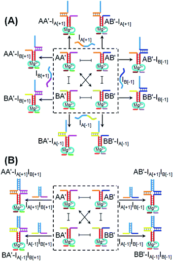
:![[thin space (1/6-em)]](https://www.rsc.org/images/entities/char_2009.gif) 2 demultiplexer, we demonstrate that, in the presence of appropriate input triggers, the same CDN “X” activates a 3 × 3 ternary multiplication matrix.72Fig. 8A introduces the CDN “X” and the respective inputs that interact with CDN “X” to operate the 3 × 3 multiplication matrix. Four inputs IA[+1], IB[+1], IA[−1] and IB[−1] are used to interact with the CDN “X” system. Each of these inputs includes an “arch-like” strand configuration that hybridizes with the respective constituents. Nonetheless, the hybridization processes do not affect the stabilities of the constituents of the CDN “X”, since they hybridize with only one “arm” of the constituents and, thus, do not reconfigure the CDN. Hence, the DNAzyme reporter units associated with the constituents are not affected by the inputs, [−1] × [0] = 0 and [+1] × [0] = 0. The inputs are, pre-engineered to yield interhybridized pairs that stabilize the four constituents of CDN “X”, and can be considered as products of the multiplication matrix, e.g., IA[+1]IB[+1] stabilizes AA′; IA[−1]IB[+1] stabilizes BA′; IA[+1]IB[−1] stabilizes AB′ and IA[−1]IB[−1] stabilizes BB′, Fig. 8B. Assuming that the output of the 3 × 3 multiplication matrix is the readout signal of the reporter unit associated with the constituent AA′, the treatment of the CDN “X” with IA[+1]IB[+1] will upregulate AA′, output “1”; treatment of the CDN “X” with IA[−1]IB[−1] stabilizes BB′ and, concomitantly, AA′, thus, leading to the output “1”, [−1] × [−1] = 1 and [+1] × [+1] = 1. Subjecting the CDN to the inputs IB[−1]IA[+1] or IB[+1]IA[−1] stabilizes the constituents AB′ and BA′, respectively, resulting in their upregulation and the concomitant downregulation of AA′ and BB′. As a result, the output signal of AA′ in the presence of these two products will be downregulated, as compared to the original output value of AA′, prior to the interaction with these input products, output “−1” and “−1”, respectively, [−1] × [+1] = −1 and [+1] × [−1] = −1.
2 demultiplexer, we demonstrate that, in the presence of appropriate input triggers, the same CDN “X” activates a 3 × 3 ternary multiplication matrix.72Fig. 8A introduces the CDN “X” and the respective inputs that interact with CDN “X” to operate the 3 × 3 multiplication matrix. Four inputs IA[+1], IB[+1], IA[−1] and IB[−1] are used to interact with the CDN “X” system. Each of these inputs includes an “arch-like” strand configuration that hybridizes with the respective constituents. Nonetheless, the hybridization processes do not affect the stabilities of the constituents of the CDN “X”, since they hybridize with only one “arm” of the constituents and, thus, do not reconfigure the CDN. Hence, the DNAzyme reporter units associated with the constituents are not affected by the inputs, [−1] × [0] = 0 and [+1] × [0] = 0. The inputs are, pre-engineered to yield interhybridized pairs that stabilize the four constituents of CDN “X”, and can be considered as products of the multiplication matrix, e.g., IA[+1]IB[+1] stabilizes AA′; IA[−1]IB[+1] stabilizes BA′; IA[+1]IB[−1] stabilizes AB′ and IA[−1]IB[−1] stabilizes BB′, Fig. 8B. Assuming that the output of the 3 × 3 multiplication matrix is the readout signal of the reporter unit associated with the constituent AA′, the treatment of the CDN “X” with IA[+1]IB[+1] will upregulate AA′, output “1”; treatment of the CDN “X” with IA[−1]IB[−1] stabilizes BB′ and, concomitantly, AA′, thus, leading to the output “1”, [−1] × [−1] = 1 and [+1] × [+1] = 1. Subjecting the CDN to the inputs IB[−1]IA[+1] or IB[+1]IA[−1] stabilizes the constituents AB′ and BA′, respectively, resulting in their upregulation and the concomitant downregulation of AA′ and BB′. As a result, the output signal of AA′ in the presence of these two products will be downregulated, as compared to the original output value of AA′, prior to the interaction with these input products, output “−1” and “−1”, respectively, [−1] × [+1] = −1 and [+1] × [−1] = −1.
Fig. 9 depicts the experimental time-dependent fluorescence changes of the output AA′ reporter unit, upon subjecting the CDN “X” to the respective pairs of input products, in comparison to the time-dependent fluorescence changes generated by the reporter unit associated with AA′ prior to interaction to the products inputs. As expected, subjecting the CDN “X” to the products IA[−1]IB[−1] and IA[+1]IB[+1] leads to the upregulation of the output signal of AA′ by 53% and 44%, respectively, output “+1”, whereas the interaction of IA[−1]IB[+1] and IB[−1]IA[+1] leads to the downregulation of the AA′ output by −29% and −43%, respectively, resulting in of “−1” output. The 3 × 3 multiplication matrix generated upon subjecting CDN “X” to the set of inputs summarized in a form of a “bar” presentation in Fig. 9B. Using the domain of percentage changes in the region of +0.12 to −0.12 as threshold of “0” output of the reporter unit, the percentage changes above or below the threshold values are defined as “+1” or “−1”, respectively, Fig. 9B, and the respective truth table, Fig. 9C. Note, however, that the 3 × 3 ternary multiplication matrix used the reporter associated with AA′ as output. In principle, the responses of the three reporters associated with the other three constituents could also be “outputs” for the same multiplication matrix, thus enhancing the reliability of the computation circuit (time-dependent fluorescence changes of the reporter units associated with the different output constituents, bar presentation corresponding to the contents of the output constituents, and electrophoretic image, see Fig. S17–S20†).
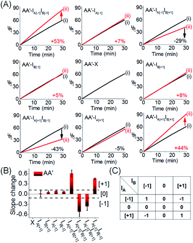 | ||
| Fig. 9 (A) Time-dependent fluorescence changes generated by the reporter unit associated with AA′ upon subjecting CDN “X” to the different inputs outlined in Fig. 8. Curves (i) correspond to the response of the AA′ reporter unit before the application of any inputs, curves (ii) correspond to the results of applying different inputs. For the time-dependent fluorescence changes of the reporter units associated with the other three constituents see ESI Fig. S17A–S19A.† (B) Bar presentation of the fluorescence changes associated with the constituent AA′ in the presence of the different inputs. Error bars derived from N = 3 experiments. (C) Truth-table corresponding to the ternary 3 × 3 multiplication matrix generated by AA′ (for the bar presentation of the fluorescence changes associated with the other three constituents and the comprehensive 3 × 3 multiplication matrix generated by all of the constituents of the CDN “X”, see Fig. S17B–S19B†). | ||
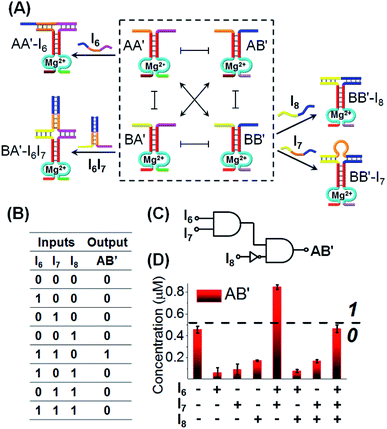
Finally, we applied CDN “X” to operate a logic circuitry consisting of an AND–InhibitAND cascade, Fig. 10. The first layer of the cascade includes the AND gate, where the activity of the DNAzyme reporter unit associated with AB′ provides the output signal of the entire cascade. Subjecting CDN “X” to input I6 stabilizes constituent AA′, leading to the upregulation of AA′ and BB′, and the downregulation of AB′ and BA′. Thus, the output signal is lower than the background, threshold, output of the non-treated network, output “0”. Similarly, subjecting CDN “X” to input I7, stabilizes constituent BB′, leading to its upregulation and to the downregulation of AB′, output “0”. Treatment of the CDN “X” with the two inputs, I6 and I7, results in the interbridging of the strands and the resulting duplex I6I7 hybridized with BA′. The stabilization of BA′ is accompanied by its upregulation, downregulation of AA′ and BB′, and the concomitant upregulation of AB′. The upregulation of the output reporter DNAzyme, AB′ results in an enhanced output signal, as compared to the original background, threshold signal, output “1”. That is, the first layer of the circuitry corresponds to an AND gate using the reporter AB′ as output (that is intensified in the presence of I6I7). The second layer of the logic cascade includes the coupling of the input I8 with the CDN “X”. The input I8 hybridizes with the constituent BB′ leading to its stabilization and upregulation, and to the concomitant downregulation of the output constituent AB′, output “0”. The stabilization of the constituent BB′ by I8 and the upregulation of BB′ opposes, however, the stabilization of BA′ by the inputs I6I7. Thus, the stabilization of the constituent BB′ is accompanied by the weakening of the output signal of AB′, leading to a response of AB′ that is below the threshold output of AB′ prior to the application of the inputs, output “0”. Thus, upon coupling the AB′ output of the first layer gate with input I8 acting as input of the second gate layer leads to a “0” output and the operation of an InhibitAND gate. The expected truth-table of the two layer cascade is displayed in Fig. 10B, and the schematic formation of the AND–InhibitAND cascade is shown in Fig. 10C. The experimental results corresponding to the time-dependent fluorescence changes of all reporter units associated with the constituents of CDN “X”, before and after treatment with the inputs I6, I7 and I8 are displayed in Fig. S21–S25, ESI.† Using the appropriate calibration curves, one may evaluate the concentrations of the respective constituents, in the presence of the appropriate combinations of triggers. For example, the content of AB′ was used as the output signal to probe the activity of the CDN “X” and the results are presented in the form of a bar presentation in Fig. 10D. The results confirm that the two layer cascade follow an AND–InhibitAND cascade. Note, that our discussion has applied the reporter signal of constituent AB′ as output for the AND–InhibitAND cascade. In principle, one may use the reporter units of the other three constituents as outputs for the single AND–InhibitAND cascade circuitry, Fig. S26.† Furthermore, one may realize the versatility and modularity of CDN “X” to operate, in the presence of other inputs, a variety of other cascaded circuitries. For example, we schematically introduce the assembly of AND–OR cascade, Fig. S27.† Furthermore, by applying an additional input I12 on the computational module shown in Fig. 10, fan-out capacities of the system were demonstrated, see Fig. S28A–C.† The cascade gates reveal the advantage of using DNA as function material to construct the gates. The possibility to delicately control the inter-nucleic acid hybridization by the number and nature of complementary base-pairs provides a useful means to eliminate “crosstalk” perturbing interactions and yield pure operations of the constituents.
The five examples applying nucleic acid-based CDN for logic operations and computing circuits introduce important features to the area of DNA computing: (i) one CDN system, CDN “X” consisting of only four DNA strands, can be used as a versatile “information processing center”, Scheme 2. In the presence of appropriate pre-engineered inputs, a variety of output circuits may be envisaged. (ii) The mapping of the response of the CDN module on AND and XOR gates provides a universal set of gates. (iii) The orthogonal reconfiguration of the four constituents of the CDN enabled the parallel operation of two logic gates in a single CDN module, e.g. the AND and XOR gates. (iv) The availability of four constituents in the CDN processing module, where each of the constituents includes a reporter unit, and allows the parallel readout of the processed logic circuit by four pairs of output signals that are logically equivalent. This redundancy introduces robustness and a reliable readout of the circuit performance, features that are of particular significance in molecular computing. In addition, the four output signals permit the subsequent fan-out of the information processed CDN module to other CDNs. (v) The demonstrated feasibility to evolve CDNs, to design CDN of increased multiplicity, to tailor CDN revealing feedback-driven reconfiguration, and the design of triggered hierarchically-guided CDNs, provide versatile means to construct logic circuits of enhanced complexities while resolving fundamental computational difficulties, such as signal amplification of weakening cascaded logic pathways.73,74 (vi) It should be noted that all CDN-guided logic gates and circuits discussed in the paper demonstrated the unidirectional input(s)-guided reconfiguration of the computing module to execute the respective logic operation. Any of the described system can be, however, reset to the original computing module by the addition of the counter input(s), that displace the input(s) associated with the computing modules, without the addition of any other component, except the counter inputs. Considering the fact that the concentrations of the substrates corresponding to the different reporter units exist in excess in the systems, and realizing that the output signals of the reporter units are read-out on a time-scale of 10 to 30 minutes, yet due to the excess of the reporter substrates, the linear fluorescence changes proceed on a time-scale of five hours, the resetting of the computing modules for 5 times should be feasible.
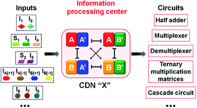 | ||
| Scheme 2 Summary of an input-triggered CDN that guides the operation of a set of logic gates and computing circuits. | ||
Conclusion
The study introduced the primary application of the CDN concept for DNA logic gate operation. The unique outcome of the study is the demonstration that one common CDN module can be applied as a functional unit, in the presence of different inputs, to activate a set of universal logic gates and logic circuits. The use of the CDN as computational module introduced significant advantages over traditional DNA logic gates and circuits reflected by the generation of four parallel redundant output signals providing computational accuracy and gate stability, and offering fan-out capacity for circuits of enhanced complexities. Realizing the reported complexities of CDNs, e.g., the operation of 3 × 3 CDNs67 or three-dimensional CDNs68 and the control over the hierarchical adaptive reconfiguration of these CDNs, the present study paves means to design future logic gate cascades, fan-in and fan-out gates and more. Furthermore, many natural processes and their outcome are guided by dynamically-driven networks. From a basic scientific view, the present study is inspired by these biological transformations where dynamic changes induced by chemical switching events control the spatiotemporal access to stored information.75 Thus, beyond the immediate advances introduced by the study to DNA computing systems, it provides, in our opinion, guiding scientific concepts to develop other molecular, macromolecular, or biomolecular computing circuits.The fact that the CDN is composed of dynamically interchangeable, intercommunicating, constituents that can be triggered by a set of different inputs into a variety of reconfigured compositions provides versatile means to process information. The role of the inputs is to displace the equilibrium between the constituents using Le Chatelier principle,76 which provides a thermodynamical control for programming the CDNs. In addition, the conjugation of four DNAzyme reporter units acting as outputs for the reconfigured network assembly introduces a general path for the fan-out of the information processed by the CDN module. These unique capabilities of CDNs were successfully applied by introducing a single [2 × 2] CDN that operated a half-adder, a 2![[thin space (1/6-em)]](https://www.rsc.org/images/entities/char_2009.gif) :
:![[thin space (1/6-em)]](https://www.rsc.org/images/entities/char_2009.gif) 1 multiplexer, a 1
1 multiplexer, a 1![[thin space (1/6-em)]](https://www.rsc.org/images/entities/char_2009.gif) :
:![[thin space (1/6-em)]](https://www.rsc.org/images/entities/char_2009.gif) 2 demultiplexer, a ternary 3 × 3 multiplication matrix and an AND–InhibitAND cascade. Each of these logic operations and computing circuits was fanned-out into four different outputs, demonstrating the abilities of the CDN to process information. Realizing the fundamental advantages of applying CDNs as functional modules for operating logic gates and computational circuits, one may envisage the further development of the concept: (i) by designing other inputs, other CDN-driven logic gates and logic cascades are feasible. (ii) The input-driven reconfiguration of the CDNs is based on a thermodynamic control. One could now try to manipulate the rate at which the new equilibrium is reached so as to implement time-dependent logic operations. (iii) The ability to evolve and communicate networks65,73 provides a means to design CDN-guided complex cascaded logic gates and computing circuits. (iv) The present study has applied the simple [2 × 2] CDN module for logics. Nonetheless, DNA-based CDNs of higher complexity, e.g. [2 × 3] and [3 × 3] CDNs were designed.67 This paves principles for indispensable degrees for compression, processing and particularly hierarchically-adaptive computation with CDN modules (for that an discussion on the input-triggered hierarchically adaptive reconfiguration of [3 × 3] CDNs, see ref. 67)
2 demultiplexer, a ternary 3 × 3 multiplication matrix and an AND–InhibitAND cascade. Each of these logic operations and computing circuits was fanned-out into four different outputs, demonstrating the abilities of the CDN to process information. Realizing the fundamental advantages of applying CDNs as functional modules for operating logic gates and computational circuits, one may envisage the further development of the concept: (i) by designing other inputs, other CDN-driven logic gates and logic cascades are feasible. (ii) The input-driven reconfiguration of the CDNs is based on a thermodynamic control. One could now try to manipulate the rate at which the new equilibrium is reached so as to implement time-dependent logic operations. (iii) The ability to evolve and communicate networks65,73 provides a means to design CDN-guided complex cascaded logic gates and computing circuits. (iv) The present study has applied the simple [2 × 2] CDN module for logics. Nonetheless, DNA-based CDNs of higher complexity, e.g. [2 × 3] and [3 × 3] CDNs were designed.67 This paves principles for indispensable degrees for compression, processing and particularly hierarchically-adaptive computation with CDN modules (for that an discussion on the input-triggered hierarchically adaptive reconfiguration of [3 × 3] CDNs, see ref. 67)
As for all DNA computing systems, the question of practical applications, and the suggestion of feasible uses of such systems beyond basic science, are still challenges. DNA computing systems are relatively slow and include expensive and sensitive ingredients, and limited recyclability requires the identification of DNA computing assemblies for each target applications. Nonetheless, the interfacing of DNA computing systems with cells for diagnostic and therapeutic application is a natural path to follow. The fact that the computing modules are triggered by nucleic acid inputs, and realizing constituents of the computing modules include catalytic (DNAzyme) counterparts that can be used for the programmed synthesis of sequence-specific output strands suggest various possible theranostic applications of DNA computing devices. For example, triggering of the computing modules by specific miRNA inputs could provide autonomous sensing and detection means of different diseases such as cancer.77 In addition, the biomarker-input-triggered logic activation of the DNAzyme units could provide versatile means to synthesize programmed sequences such as SiDNA or gene-guided transcription and translation of proteins.10 Nonetheless, such farseeing vision of DNA coupling will require further advancements and effective means to image the intracellular logic operation.
Conflicts of interest
There are no conflicts to declare.Acknowledgements
This study is supported by the Israel Science Foundation. FR thanks Fonds National de la Recherche, FRS-FNRS, Belgium, for its support (MONACOMP #T0205.20).Notes and references
- I. Willner, B. Shlyahovsky, M. Zayats and B. Willner, Chem. Soc. Rev., 2008, 37, 1153 RSC.
- T. Fu, Y. Lyu, H. Liu, R. Peng, X. Zhang, M. Ye and W. Tan, Trends Biochem. Sci., 2018, 43, 547–560 CrossRef CAS PubMed.
- D. Fan, J. Wang, E. Wang and S. Dong, Adv. Sci., 2020, 2001766, DOI:10.1002/advs.202001766.
- H. Sun, J. Ren and X. Qu, Acc. Chem. Res., 2016, 49, 461–470 CrossRef CAS PubMed.
- L. Ceze, J. Nivala and K. Strauss, Nat. Rev. Genet., 2019, 20, 456–466 CrossRef CAS PubMed.
- G. Gines, A. S. Zadorin, J. C. Galas, T. Fujii, A. Estevez-Torres and Y. Rondelez, Nat. Nanotechnol., 2017, 12, 351–359 CrossRef CAS PubMed.
- C. Mao, T. H. LaBean, J. H. Reif and N. C. Seeman, Nature, 2000, 407, 493–496 CrossRef CAS PubMed.
- X. Song and J. Reif, ACS Nano, 2019, 13, 6256–6268 CrossRef CAS PubMed.
- J. Li, A. A. Green, H. Yan and C. Fan, Nat. Chem., 2017, 9, 1056–1067 CrossRef CAS PubMed.
- A. A. Green, J. Kim, D. Ma, P. A. Silver, J. J. Collins and P. Yin, Nature, 2017, 548, 117–121 CrossRef CAS PubMed.
- J. Hemphill and A. Deiters, J. Am. Chem. Soc., 2013, 135, 10512–10518 CrossRef CAS PubMed.
- T. Li, D. Ackermann, A. M. Hall and M. Famulok, J. Am. Chem. Soc., 2012, 134, 3508–3516 CrossRef CAS PubMed.
- Y. Hu, A. Cecconello, A. Idili, F. Ricci and I. Willner, Angew. Chem., Int. Ed., 2017, 56, 15210–15233 CrossRef CAS PubMed.
- H. Pei, L. Liang, G. Yao, J. Li, Q. Huang and C. Fan, Angew. Chem., Int. Ed., 2012, 51, 9020–9024 CrossRef CAS PubMed.
- T. Li, E. Wang and S. Dong, J. Am. Chem. Soc., 2009, 131, 15082–15083 CrossRef CAS PubMed.
- K. S. Park, C. Jung and H. G. Park, Angew. Chem., 2010, 122, 9951–9954 CrossRef.
- Y. Miyake, H. Togashi, M. Tashiro, H. Yamaguchi, S. Oda, M. Kudo, Y. Tanaka, Y. Kondo, R. Sawa, T. Fujimoto, T. Machinami and A. Ono, J. Am. Chem. Soc., 2006, 128, 2172–2173 CrossRef CAS PubMed.
- L. Qian, E. Winfree and J. Bruck, Nature, 2011, 475, 368–372 CrossRef CAS PubMed.
- L. Qian and E. Winfree, Science, 2011, 332, 1196–1201 CrossRef CAS PubMed.
- L. Feng, Z. Lyu, A. Offenhäusser and D. Mayer, Angew. Chem., Int. Ed., 2015, 54, 7693–7697 CrossRef CAS PubMed.
- R. Peng, X. Zheng, Y. Lyu, L. Xu, X. Zhang, G. Ke, Q. Liu, C. You, S. Huan and W. Tan, J. Am. Chem. Soc., 2018, 140, 9793–9796 CrossRef CAS PubMed.
- J. Bath and A. J. Turberfield, Nat. Nanotechnol., 2007, 2, 275–284 CrossRef CAS PubMed.
- G. Yao, J. Li, Q. Li, X. Chen, X. Liu, F. Wang, Z. Qu, Z. Ge, R. P. Narayanan, D. Williams, H. Pei, X. Zuo, L. Wang, H. Yan, B. L. Feringa and C. Fan, Nat. Mater., 2019, 19, 781–788 CrossRef PubMed.
- T. Song, A. Eshra, S. Shah, H. Bui, D. Fu, M. Yang, R. Mokhtar and J. Reif, Nat. Nanotechnol., 2019, 14, 1075–1081 CrossRef CAS PubMed.
- D. Y. Zhang and E. Winfree, J. Am. Chem. Soc., 2009, 131, 17303–17314 CrossRef CAS PubMed.
- G. Seelig, D. Soloveichik, D. Y. Zhang and E. Winfree, Science, 2006, 314, 1585–1588 CrossRef CAS PubMed.
- Y. Benenson, B. Gil, U. Ben-Dor, R. Adar and E. Shapiro, Nature, 2004, 429, 423–429 CrossRef CAS PubMed.
- Y. Zhang, Z. Shuai, H. Zhou, Z. Luo, B. Liu, Y. Zhang, L. Zhang, S. Chen, J. Chao, L. Weng, Q. Fan, C. Fan, W. Huang and L. Wang, J. Am. Chem. Soc., 2018, 140, 3988–3993 CrossRef CAS PubMed.
- J. Elbaz, O. Lioubashevski, F. Wang, F. Remacle, R. D. Levine and I. Willner, Nat. Nanotechnol., 2010, 5, 417–422 CrossRef CAS PubMed.
- R. Orbach, B. Willner and I. Willner, Chem. Commun., 2015, 51, 4144–4160 RSC.
- J. Zhang and Y. Lu, Angew. Chem., Int. Ed., 2018, 57, 9702–9706 CrossRef CAS PubMed.
- S. Bi, Y. Yan, S. Hao and S. Zhang, Angew. Chem., Int. Ed., 2010, 49, 4438–4442 CrossRef CAS PubMed.
- J. Zhu, L. Zhang, T. Li, S. Dong and E. Wang, Adv. Mater., 2013, 25, 2440–2444 CrossRef CAS PubMed.
- H. Lederman, J. Macdonald, D. Stefanovic and M. N. Stojanovic, Biochemistry, 2006, 45, 1194–1199 CrossRef CAS PubMed.
- J. Elbaz, F. Wang, F. Remacle and I. Willner, Nano Lett., 2012, 12, 6049–6054 CrossRef CAS PubMed.
- A. J. Genot, J. Bath and A. J. Turberfield, J. Am. Chem. Soc., 2011, 133, 20080–20083 CrossRef CAS PubMed.
- R. Orbach, F. Remacle, R. D. Levine and I. Willner, Proc. Natl. Acad. Sci. U. S. A., 2012, 109, 21228–21233 CrossRef CAS PubMed.
- F. Wang, H. Lv, Q. Li, J. Li, X. Zhang, J. Shi, L. Wang and C. Fan, Nat. Commun., 2020, 11, 121 CrossRef CAS PubMed.
- B. Fresch, M. Cipolloni, T.-M. Yan, E. Collini, R. D. Levine and F. Remacle, J. Phys. Chem. Lett., 2015, 6, 1714–1718 CrossRef CAS PubMed.
- R. Orbach, F. Remacle, R. D. Levine and I. Willner, Chem. Sci., 2014, 5, 1074 RSC.
- H. Su, J. Xu, Q. Wang, F. Wang and X. Zhou, Nat. Commun., 2019, 10, 5390 CrossRef PubMed.
- S. Chen, Z. Xu, W. Yang, X. Lin, J. Li, J. Li and H. Yang, Angew. Chem., Int. Ed., 2019, 58, 18186–18190 CrossRef CAS PubMed.
- W. Li, Y. Yang, H. Yan and Y. Liu, Nano Lett., 2013, 13, 2980–2988 CrossRef CAS PubMed.
- D. Fan, K. Wang, J. Zhu, Y. Xia, Y. Han, Y. Liu and E. Wang, Chem. Sci., 2015, 6, 1973–1978 RSC.
- H. Liu, J. Wang, S. Song, C. Fan and K. V. Gothelf, Nat. Commun., 2015, 6, 10089 CrossRef CAS PubMed.
- G. Chatterjee, N. Dalchau, R. A. Muscat, A. Phillips and G. Seelig, Nat. Nanotechnol., 2017, 12, 920–927 CrossRef CAS PubMed.
- C. Zhang, J. Yang, S. Jiang, Y. Liu and H. Yan, Nano Lett., 2015, 16, 736–741 CrossRef PubMed.
- L. Yue, S. Wang, Z. Zhou and I. Willner, J. Am. Chem. Soc., 2020, 142(52), 21577–21594 CrossRef CAS PubMed.
- G. Men and J.-M. Lehn, Chem. Sci., 2019, 10, 90–98 RSC.
- G. Vantomme, S. Jiang and J.-M. Lehn, J. Am. Chem. Soc., 2014, 136, 9509–9518 CrossRef CAS PubMed.
- F. C. Simmel, B. Yurke and H. R. Singh, Chem. Rev., 2019, 119, 6326–6369 CAS.
- D. Y. Zhang, A. J. Turberfield, B. Yurke and E. Winfree, Science, 2007, 318, 1121–1125 CrossRef CAS PubMed.
- D. Y. Zhang and G. Seelig, Nat. Chem., 2011, 3, 103–113 CrossRef CAS PubMed.
- A. Amodio, B. Zhao, A. Porchetta, A. Idili, M. Castronovo, C. Fan and F. Ricci, J. Am. Chem. Soc., 2014, 136, 16469–16472 CrossRef CAS PubMed.
- J.-L. Mergny and D. Sen, Chem. Rev., 2019, 119, 6290–6325 CrossRef CAS PubMed.
- S. N. Georgiades, N. H. AbdKarim, K. Suntharalingam and R. Vilar, Angew. Chem., Int. Ed., 2010, 49, 4020–4034 CrossRef CAS PubMed.
- Y. Kamiya and H. Asanuma, Acc. Chem. Res., 2014, 47, 1663–1672 CrossRef CAS PubMed.
- Y. Kim, J. A. Phillips, H. Liu, H. Kang and W. Tan, Proc. Natl. Acad. Sci. U. S. A., 2009, 106, 6489–6494 CrossRef CAS PubMed.
- M. W. Haydell, M. Centola, V. Adam, J. Valero and M. Famulok, J. Am. Chem. Soc., 2018, 140, 16868–16872 CrossRef CAS PubMed.
- R. R. Breaker and G. F. Joyce, Chem. Biol., 1995, 2, 655–660 CrossRef CAS.
- M. Famulok, J. S. Hartig and G. Mayer, Chem. Rev., 2007, 107, 3715–3743 CrossRef CAS PubMed.
- R. J. Lake, Z. Yang, J. Zhang and Y. Lu, Acc. Chem. Res., 2019, 52, 3275–3286 CrossRef CAS PubMed.
- S. Wang, L. Yue, Z. Shpilt, A. Cecconello, J. S. Kahn, J.-M. Lehn and I. Willner, J. Am. Chem. Soc., 2017, 139, 9662–9671 CrossRef CAS PubMed.
- L. Yue, S. Wang, V. Wulf, S. Lilienthal, F. Remacle, R. D. Levine and I. Willner, Proc. Natl. Acad. Sci. U. S. A., 2019, 116, 2843–2848 CrossRef CAS PubMed.
- L. Yue, S. Wang, S. Lilienthal, V. Wulf, F. Remacle, R. D. Levine and I. Willner, J. Am. Chem. Soc., 2018, 140, 8721–8731 CrossRef CAS PubMed.
- S. Wang, L. Yue, Z. Y. Li, J. Zhang, H. Tian and I. Willner, Angew. Chem., Int. Ed., 2018, 57, 8105–8109 CrossRef CAS PubMed.
- Z. Zhou, L. Yue, S. Wang, J.-M. Lehn and I. Willner, J. Am. Chem. Soc., 2018, 140, 12077–12089 CrossRef CAS PubMed.
- L. Yue, S. Wang and I. Willner, J. Am. Chem. Soc., 2019, 141, 16461–16470 CrossRef CAS PubMed.
- L. Yue, S. Wang, V. Wulf and I. Willner, Nat. Commun., 2019, 10, 4774 CrossRef PubMed.
- Z. Zhou, X. Liu, L. Yue and I. Willner, ACS Nano, 2018, 12, 10725–10735 CrossRef CAS PubMed.
- Z. Zhou, P. Zhang, L. Yue and I. Willner, Nano Lett., 2019, 19, 7540–7547 CrossRef CAS.
- R. Orbach, S. Lilienthal, M. Klein, R. D. Levine, F. Remacle and I. Willner, Chem. Sci., 2015, 6, 1288–1292 RSC.
- L. Yue, V. Wulf, S. Wang and I. Willner, Angew. Chem., Int. Ed., 2019, 58, 12238–12245 CrossRef CAS.
- Z. Zhou, J. Wang and I. Willner, J. Am. Chem. Soc., 2020, 143, 241–251 CrossRef.
- A. N. Boettiger, B. Bintu, J. R. Moffitt, S. Wang, B. J. Beliveau, G. Fudenberg, M. Imakaev, L. A. Mirny, C.-t. Wu and X. Zhuang, Nature, 2016, 529, 418–422 CrossRef CAS PubMed.
- V. B. E. Thomsen, J. Chem. Educ., 2000, 77, 173–176 CrossRef CAS.
- C. Zhang, Y. Zhao, X. Xu, R. Xu, H. Li, X. Teng, Y. Du, Y. Miao, H.-c. Lin and D. Han, Nat. Nanotechnol., 2020, 15, 709–715 CrossRef CAS PubMed.
Footnote |
| † Electronic supplementary information (ESI) available. See DOI: 10.1039/d1sc01098k |
| This journal is © The Royal Society of Chemistry 2021 |

