 Open Access Article
Creative Commons Attribution 3.0 Unported Licence
Trialkylammonium salt degradation: implications for methylation and cross-coupling†
Jack B.
Washington
a,
Michele
Assante
b,
Chunhui
Yan
 a,
David
McKinney
a,
Vanessa
Juba
a,
Andrew G.
Leach
a,
David
McKinney
a,
Vanessa
Juba
a,
Andrew G.
Leach
 c,
Sharon E.
Baillie
d and
Marc
Reid
 *a
*a
aWestCHEM Department of Pure and Applied Chemistry, University of Strathclyde, Thomas Graham Building, 295 Cathedral Street, Glasgow, UK. E-mail: marc.reid.100@strath.ac.uk
bSchool of Pharmacy and Biomolecular Sciences, Liverpool John Moores University, Byrom Street, Liverpool, UK
cDivision of Pharmacy and Optometry, University of Manchester, Stopford Building, Oxford Road, Manchester, UK
dGlaxoSmithKline, Shewalton Road, Irvine, North Ayrshire, UK
First published on 13th April 2021
Abstract
Trialkylammonium (most notably N,N,N-trimethylanilinium) salts are known to display dual reactivity through both the aryl group and the N-methyl groups. These salts have thus been widely applied in cross-coupling, aryl etherification, fluorine radiolabelling, phase-transfer catalysis, supramolecular recognition, polymer design, and (more recently) methylation. However, their application as electrophilic methylating reagents remains somewhat underexplored, and an understanding of their arylation versus methylation reactivities is lacking. This study presents a mechanistic degradation analysis of N,N,N-trimethylanilinium salts and highlights the implications for synthetic applications of this important class of salts. Kinetic degradation studies, in both solid and solution phases, have delivered insights into the physical and chemical parameters affecting anilinium salt stability. 1H NMR kinetic analysis of salt degradation has evidenced thermal degradation to methyl iodide and the parent aniline, consistent with a closed-shell SN2-centred degradative pathway, and methyl iodide being the key reactive species in applied methylation procedures. Furthermore, the effect of halide and non-nucleophilic counterions on salt degradation has been investigated, along with deuterium isotope and solvent effects. New mechanistic insights have enabled the investigation of the use of trimethylanilinium salts in O-methylation and in improved cross-coupling strategies. Finally, detailed computational studies have helped highlight limitations in the current state-of-the-art of solvation modelling of reaction in which the bulk medium undergoes experimentally observable changes over the reaction timecourse.
Introduction
Applications and divergent reactivity of trialkylammonium salts
Trialkylammonium (specifically N,N,N-trimethylanilinium) salts have found wide-ranging applications in synthesis, spanning phase-transfer catalysis,1 supramolecular ion-pairing catalysis,2,3 host-guest binding studies,4O-methylation,5O-arylation,6 heteroatom arylations,7 C–H methylation,8C-arylation,9–11 fluorine radiolabeling,12–15 organometallic ligand design,16–21 antimicrobial polymer design,22 arene reduction,23 pH sensing,24 and a range of metal-catalysed cross-coupling methodologies.25–32 The dichotomy of arylation versus methylation reactivity, while important for optimising the above-listed applications, is rarely studied in detail. Understanding the dual reactivity of N,N,N-trimethylanilinium salts thus serves as the focus of our study.Arylation methodologies are arguably the most widely studied of the above-listed anilinium salt applications. Pioneering developments by Wenkert et al. involved a nickel-catalysed Kumada-type coupling between Grignard reagents and trimethylanilinium iodides to generate biaryls via C–C bond formation (Fig. 1, Part B).9 Later developments from Reeves used trimethylanilinium triflates and aryl Grignard reagents with a palladium catalyst to produce functionalised biaryl motifs in high yields under mild conditions.10 Similarly, MacMillan et al. found that trimethylanilinium triflates were suitable coupling partners with arylboronic acids in Suzuki reactions.11 Other notable examples where trimethylanilinium salts have been used as electrophilic coupling partners include Negishi coupling,33 borylation,34,35 amination,36 and azole arylation.37 In contrast to the wealth of transition-metal catalysed arylation reactions using anilinium salts, Chatani's team provided a rare demonstration that N,N,N-trimethylanilinium iodide can be used to transfer a methyl (as opposed to phenyl) group in nickel-catalysed C(sp2)–H and C(sp3)–H bond formations (Fig. 1, Part A).8 Pioneering nickel-catalysed arene reduction methods from Rand and Montgomery23 showed that ligand and solvent variations could be exploited to enable either C–H or C–Si bond formation from the same anilinium salt source (Fig. 1, Parts C and D). Base-mediated reactions with anilinium salts display a similar dichotomy in arylation versus methylation (Fig. 1, Parts E and F). To optimise the predictable use of trimethylanilinium salts in synthesis, a structured mechanistic analysis of their arylation and methylation reactivities is required. Herein, we present our investigation of the factors governing this dichotomous reactivity (Fig. 1, Part G).
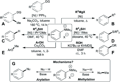 | ||
| Fig. 1 Demonstration of dichotomous reactivity of trimethylanilinium salts in: (A) C–H methylation,8 (B) Kumada coupling,9 (C) arene reduction,23 (D) silylation,23 (E) phenol methylation,5 and (F) alcohol arylation.6 Part (G) summarises the dual reactivity of trimethylanilinium salts and the key mechanistic problem investigated in this study. | ||
Drivers towards understanding the methylating ability of anilinium salts
The presence or absence of small methyl groups in organic molecules can bring about large changes in physicochemical properties.38,39 This has been a particular focus in drug design where the installation of methyl groups can have drastic effects on solubility, potency and selectivity; this contested phenomenon is dubbed the magic methyl effect.40,41 As such, the present study to understand trimethylanilinium salts is, in part, an answer to the call for new methylation reactions.40 Parallel to drug design, formal access to highly toxic electrophilic methyl halide reagents in situ via anilinium salts may provide safer alternatives to more widely known carcinogenic and low-boiling methylating reagents.42Of the various classes of methylating reagent available,43–46 electrophilic sources still represent a significant tool for synthetic chemists (Fig. 2). As with all reagents, toxicity, safety, scalability, and operational difficulty play a key role in the decision to use or replace said reagent.42 Within the electrophilic class of methylating reagents, quaternary ammonium salts are somewhat underexplored.44 Early examples applied tetraalkylammonium and trimethylanilinium hydroxides and halides to achieve heteroatom-alkylations.5,47–50 From the patent literature, anilinium salts have been used to achieve O-methylation in alkaloids.51,52
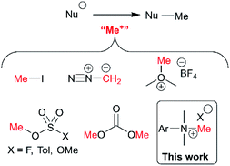 | ||
| Fig. 2 Commonly used electrophilic methylating reagents and the focus of this study to understand the place of trimethylanilinium salts among them. | ||
To the above-mentioned design and safety-focussed ends, methods that allow for methylation of a substrate in a straight-forward, safe, and predictable manner are highly desirable. Simultaneously, this directed investigation of trimethylanilinium salts, and specifically their degradation behaviour, can provide strategic insights for the myriad of aforementioned applications of these salts.
Results & discussion
Solid phase degradation analysis
To understand the potential for long-term safe storage of trimethylanilinium salts, and knowing the potential for reagent storage to cause adverse degradative effects prior to their use in synthesis,53 our studies began with an investigation of the solid-state stability of arylammonium halides (primarily aniline derivatives). Salts 1a–1c and 2a–15a composed the core structural library employed in our investigations (Fig. 3). Details on the synthesis and availability of all salts are available in the Experimental ESI (ESI; Section 3).†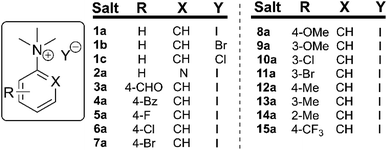 | ||
| Fig. 3 Library of N,N,N-trimethylarylammonium (phenyl and pyridyl) salts used in mechanistic degradation studies. Further anionic variations are also considered. | ||
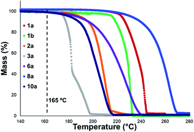
Thermal gravimetric analysis (TGA) was used to estimate relative thermal stabilities of the salt library over 40–300 °C under both argon and air atmospheres. TGA traces for the argon experiments are shown in Fig. 4. Detailed onset and peak degradation temperatures are shown in the Experimental ESI Section 4.† All salts tested were stable up to 165 °C, suggesting that storage of these compounds at room temperature would be viable. TGA traces in air were comparable to TGA results obtained under argon.
In general, compounds with more electron deficient aryl groups were more susceptible to thermal degradation (Fig. 5). All salts, with the exception of 1c (unsubstituted chloride), 3a (4-CHO) and 4a (4-Bz), showed a smooth, single-step TGA trace, potentially indicative of sublimation. It seemed plausible that the main salt decomposition products would be the parent functionalised amino arene and its respective methyl halide, arising from a retro-Menshutkin reaction.54 This hypothesis was consistent with the observation that more electron-poor salts degraded at lower temperatures than comparitively electron rich salts. Complementary thermal volumetric analysis (TVA)55 coupled with a sub-ambient distillation apparatus (TVA-SAD) was used to monitor the decomposition of anilinium iodide salts 1a (unsubstituted iodide), 7a (4-Br) and 12a (4-Me). Alongside infrared (IR) analysis, the TVA-SAD studies provided evidence that methyl iodide was generated during the thermal decomposition of these trimethylanilinium iodide salts (see Experimental ESI Section 5†). It is important to note that the relative position of an electrophilic N–Me group and a halide counterion arising from crystal packing in the solid state could contribute to different relative thermal stabilities.
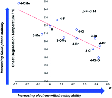 | ||
| Fig. 5 TGA analysis for the degradation of anilinium iodide salts, supporting the role of electron-withdrawing aryl substituents in promoting thermal degradation. Additional analyses for samples degraded under air can be found in the Experimental ESI, Section 4.†54 | ||
Single-point solution phase degradation studies – substituent and anion effects
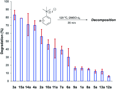
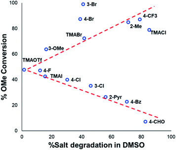
After investigating the stability of the N,N,N-trimethylanilinium halide library in the solid state, our attention turned to investigating their degradation behaviour in solution. DMSO was strategically chosen as a solvent due to its ability to solubilise the salts, enabling homogeneous 1H NMR kinetic analysis. Additionally, the high boiling point of DMSO allowed for flexible temperature studies. This solvent also links to earlier NMR kinetics investigations involving methyl iodide56 and DMSO-mediated methylation studies.57,58 Importantly, detailed studies applying solvents applicable to a broader range of methylation and catalytic chemistries is also included (see Experimental ESI Sections 20 and 22†). A graph showing the extent of degradation of each salt after a 20 min period is shown in Fig. 6. Consistent with TGA analysis, electron-poor salts were the most susceptible to thermal degradation in DMSO (Fig. 7); salts with a predominantly resonance electron-withdrawing 4-substituent, 4-formyl (3a) and 4-benzoyl (4a), were shown to degrade by 83 ± 6% and 70 ± 6%, respectively, and significantly more so than the unsubstituted iodide 1a at 16 ± 2%. Salts containing 4-chloro (6a; 30 ± 11%) and 4-bromo (7a; 39 ± 5%) substituents were only slightly destabilised with respect to 1a, while 4-methyl (12a; 6 ± 1%) was more stable than 1a. Halogen substituents have inductive electron withdrawing effects which would destabilise the anilinium cation, but they also have the competing ability to stabilise positive charge through resonance donation;59 the trend in decreasing stability from 5a to 7a (4-F > 4-Cl > 4-Br) is consistent with decreasing resonance donation down the halogen group. Conversely, 4-CF3 (15a; 79 ± 0%) shows that a strong inductive electron-withdrawing effect significantly destabilises the anilinium salt versus the unsubstituted 1a. 2-Me (14a; 71 ± 1%) shows high anilinium salt degradation over 20 min, and can presumably be attributed to the steric encumberment of the 2-Me and resulting destabilisation of the reactive quaternary nitrogen centre.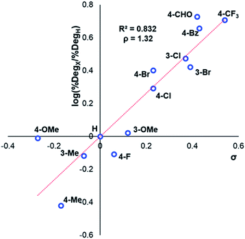 | ||
| Fig. 7 Hammett analysis of solution-phase degradation experiments shown in Fig. 5, supporting the approximation that more electron-deficient ring substituents accelerate anilinium iodide degradation by demethylation as the predominant pathway. | ||
Beyond substitution effects of the aromatic moiety on N,N,N-trimethylanilinium iodide stability, we next investigated the counter-anion effect on solution-phase stability. The degradations of N,N,N-trimethylanilinium iodide (1a), bromide (1b), and chloride (1c) were analysed after heating to 120 °C for 20 min in DMSO-d6 (Fig. 8). A clear trend emerged where degradation was more advanced after 20 min in 1c (chloride; 85 ± 2%) than 1b (bromide; 42 ± 2%) and 1a (iodide; 23 ± 3%). This is consistent with the reported order of halide nucleophilicity in polar aprotic solvents.60,61 As described below, the reaction in which methyl halide is formed is close to thermoneutrality and thus small changes in the stability of ion pairs and of carbon halide bonds can provide a thermodynamic explanation for the observed order of thermal stability in solution.12,62
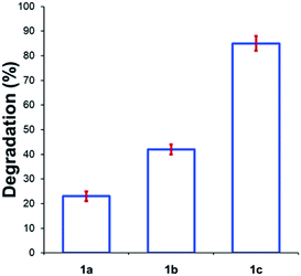 | ||
| Fig. 8 Degradation of 1a (X = I), 1b (X = Br), and 1c (X = Cl) upon heating in DMSO-d6 (0.1 M) at 120 °C for 20 min. Results and errors are taken from triplicate runs. | ||
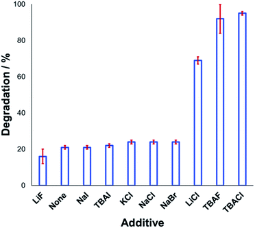
Understanding the effect of additives alongside salt degradation is relevant for applications of these anilinium salts in cross-coupling methodologies.11–17 To this end, an equimolar quantity of selected halide salts was added to solutions of 1a in DMSO-d6 and the degradation measured over 20 min at 120 °C (Fig. 9). Anilinium degradation was only accelerated by 3 of the 10 additives tested, namely LiCl, and tetrabutylammonium (TBA) salts of fluoride and chloride. The more pronounced anilinium cation degradation in the presence of TBACl versus LiCl and KCl is tentatively attributed to higher solubility of the former in DMSO. The low solubility of LiF, NaI, NaBr, NaCl, and KCl in DMSO means it also possible that there was a lower-than-calculated (or even negligible) concentration of additive halide ions in solution. Indeed, with these reactions being conducted in NMR tubes, inefficient mixing may only exacerbate any solubility issues. Addition of TBAI (i.e. additional iodide beyond that in the anilinium salt itself) proved statistically similar to no additive at all. A related report on fluoride-mediated anilinium degradation has evidenced strong ion-pairing in TBAF that undergoes immediate salt metathesis in the presence of anilinium triflates to afford anilinium fluorides.12,63
If ion-pairing indeed dictates preorganisation prior to anilinium degradation, data in Fig. 9 suggest that only the latter three additives contribute significant salt metathesis to form in situ ion pairs more prone to degradation than the parent anilinium iodide, 1a.
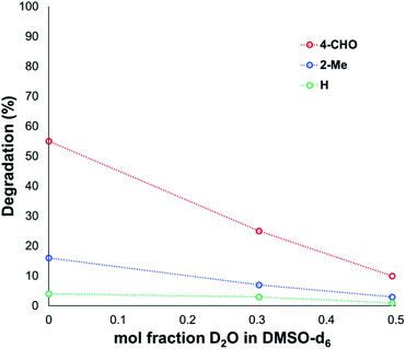
Another contributing factor in the apparent banality of LiF comes from its notably hygroscopic nature. In turn, this may have led to the introduction of water into the degradation mixture. A follow-up investigation showed that increasing water concentration – in the presence and absence of TBAF – attenuated anilinium degradation (Fig. 10), likely due to a decrease in halide nucleophilicity through more efficient anion solvation in water versus DMSO. Alternatively, the apparent decrease in halide nucleophilicity could also emerge through changes in the equilibrium, caused by enhanced solvation of ionic reactants as opposed to electronically neutral methylhalide and dimethylanilines.60,64
Whereas the increased decomposition of the anilinium salts to generate the parent aniline and methyl halide in situ may be favourable for use in methylation chemistries, minimising degradation is desired for use of anilinium salts in cross-coupling reactions.8–11,34–37 Thus, we expanded our degradation studies to include a range of substituted anilinium salts bearing non-nucleophilic anions, including several anilinium partner anions employed in cross-coupling methodologies.
The solution-phase thermal degradation of these non-halide anilinium salts are shown in Fig. 11. Non-nucleophilic counterions significantly retarded the decomposition of anilinium salts in solution, particularly when using tetrakis(3,5-bis(trifluoromethyl)phenyl)borate (BArF−) salts which proved even more thermally stable than the commonly-applied triflate salts.
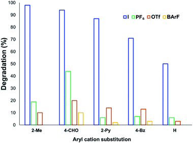 | ||
| Fig. 11 Relative degradation of N,N,N-trimethylanilinium cations partnered with weakly coordinating (less nucleophilic) anions upon heating in DMSO-d6 (0.1 M) at 120 °C for 20 min. | ||
NMR degradation kinetics
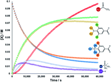
We next sought to monitor the anilinium iodide degradation reaction time course to gain a richer insight into the active mechanism(s) of degradation. From a practical perspective, we hypothesised that this additional insight could enable practitioners to use anilinium salts as a controlled source of methyl iodide generated in situ. Again, 1H NMR spectroscopy was employed to quantify reaction data. 4-Formyl-N,N,N-trimethylanilinium iodide (3a), was selected as an appropriate salt to exemplify reaction kinetics since its degradation was significantly advanced (approximately three half-lives over 16 hours) to capture relevant mechanistic information in a feasible timescale. Additionally, the formyl proton on 3a was easily identifiable in NMR spectra due its isolated downfield chemical shift. The concentration of various species were calculated against the internal standard (Fig. 12).The depletion of 3a could be monitored over time by following either the formyl, –NMe3+, and 2-aryl protons. Similarly, the evolution of 4-formyl-N,N-dimethylaniline could be seen by following the analogous –NMe2, formyl and 2-aryl protons. Furthermore, the evolution of methyl iodide (d0) could be observed in the same experiment. Interestingly, the calculated concentration of both the anilinium or aniline via aromatic and formyl protons, while being equal, were each greater than the concentration calculated via the N-methyl groups (orange vs. blue, and green vs. yellow lines in Fig. 12). This is suggestive of isotopic scrambling of N–CH3 for N–CD3 groups via interaction with the evidently non-innocent DMSO-d6 solvent. Deuterium scrambling is consistent with the emergence of trimethyl sulfoxonium (d6,h3) as a key intermediate, and DMSO-d3 as a final product.
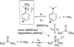
Our combined mechanistic evidence to this stage led to the tentative proposal of the mechanistic pathways summarised in Fig. 13. Mass-calibrated diffusion-ordered NMR spectroscopy (DOSY) analysis of various anilinium salts in DMSO at room temperature did not support the existence of observable concentrations of higher order salt aggregates (see Experimental ESI Section 13†), though this does not directly rule out their transient existence. We proposed that the primary pathway, via a relatively rapid approach to equilibrium, of an approximately thermoneutral self-immolative degradation led by nucleophilic attack of iodide onto a N-methyl unit of the anilinium cation, leading directly to the parent dimethylaniline and methyl iodide. In the bulk solvent, we proposed that DMSO could act as a S-centred nucleophile56,65 and attack the methyl iodide in an SN2 fashion, producing trimethylsulfoxonium iodide (TMSO-d6,h3 iodide). The TMSO-d6,h3 cation could then undergo the reverse reaction with the aniline or instead undergo a self-immolative process to release d3-methyl iodide. The incorporation of CD3 in the anilinium cation, which could remain present in the degradative aniline product, is consistent with the difference in anilinium and aniline concentrations calculated using 1H NMR spectroscopy, assuming negligible aromatic H/D exchange. In further support of this mechanistic hypothesis, methyl iodide formed at an initial rate consistent with aniline formation (Fig. 12 green and purple), while the TMSO-d6,h3 intermediate and, in turn, DMSO-d3 product formation displayed an induction period. This suggested that iodide-led degradation of anilinium cation is the major (though not exclusive) precursor to methyl transfer to solvent. In short, methyl iodide forms directly, in the first degradation step, not later.
The proposed degradation pathway takes place via a series of two-electron closed-shell processes. In order to probe for the possibility of radical degradation pathways, the degradation of 3a (4-CHO) was carried out separately under UV light and in darkness. Comparatively, the amount of 3a degraded in each case was almost identical, suggesting that photo-degradation mechanisms are not dominant (see Experimental ESI Section 15†). The absence of radical-mediated mechanisms is also supported by additional control experiments in applied methylation chemistries (see Applications section below). It is plausible that the depletion of the anilinium salt could also occur through an SNAr-type displacement of trimethylamine by the iodide counterion, however the corresponding aryl iodide was not observed (see Experimental ESI Section 14†).
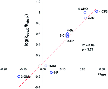
The same 1H NMR kinetics method was used to follow the degradation time course of a wider range of trimethylanilinium salts (Experimental ESI Section 11†). With the exception of 2a (2-py) and 14a (2-Me), most salts appeared to reach equilibrium that did not involve full salt degradation, consistent with a process that is approximately thermoneutral. Exploratory Swain–Lupton analysis66 was applied to solution-phase initial rate data to delineate field and resonance contributions of aryl ring substituents to salt degradation. This analysis revealed near equal field (F) and resonance (R) contributions (52% Fversus 48% R; Fig. 14). The positive reaction constant (ρ = +3.71) was consistent with earlier observations that more electron-deficient anilinium salts degrade more quickly (cf.Fig. 5 and 7). Additional Swain–Lupton analysis using the simulated k1 values based on the tentative reaction model shown in Fig. 13 lead to similar conclusions (51% R versus 49% F; ρ = +0.89; see Experimental ESI Section 11†).
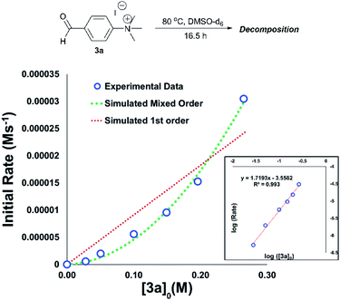
An important consideration when using a new reagent is the concentration at which it is to be used. Our time course experiments up until this point had been carried out with an anilinium salt concentration of 0.1 M in DMSO-d6 for comparability. To understand the dependence of anilinium degradation on concentration, we carried out five additional degradation monitoring experiments at various anilinium iodide starting concentrations, [3a]0. Inspection of the data revealed a deviation from linearity, providing evidence of greater than first order reaction order kinetics in [3a]0 (Fig. 15). This is not consistent with a simple self-immolation mechanism involving a single ion pair as the sole degradation mechanism, as suggested in Fig. 13. Consistent with data reported in Fig. 11, analysis of degradation of the BArF salt of [3a] via in situ NMR kinetics revealed that the background rate of degradation exclusively via the DMSO pathway (in the absence of nucleophilic iodide) was negligible at 80 °C (see Experimental ESI Section 12†). While DOSY NMR revealed no appreciable concentration of aggregates beyond the simple anilinium iodide ion pair at room temperature under the range of concentrations studied, the presented data (most notably Fig. 15) remain consistent with the possibility of degradation of the anilinium iodide salt via a transient dimeric ion pair or alternative higher order reaction.63 Dimeric degradation pathways were later considered computationally (below, and Computational ESI, Section 3†).
To estimate thermodynamic activation parameters, we conducted NMR monitoring studies between 50–80 °C. Rate constants were estimated for a simplified first order iodide-led self-immolative degradation pathway at each temperature and an Eyring plot was produced using this data (Fig. 16). The Eyring analysis revealed the activation enthalpy and entropy of the reaction as ΔH‡ = +127.0 ± 4.0 kJ mol−1 and ΔS‡ = +34.8 ± 11.7 J mol−1 K−1. ΔH‡ and ΔS‡ values for reactions involving changes in charge should be interpreted with caution as the values will include solvation dynamics and selection of appropriate rate constant from the mechanistic model(s). To cover this potential calculation error, we estimated Eyring parameters using both first and second order models, and in all circumstances, a positive entropy of activation was found. The positive activation entropy obtained in this case is hypothesised to be due to a reduced solvation demand as the charged reactants proceed to neutral products (see Computational section).67 This model is also consistent with the reaction proceeding through ion pairs wherein the translational entropy penalty of bringing electrophile and nucleophile together has largely been paid. The overall ΔG‡ = +114.7 kJ mol−1 (+27.4 kcal mol−1) derived from these calculations is in good agreement with the related DFT-calculated barrier of +116.7 kJ mol−1 (27.9 kcal mol−1; see below).
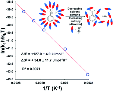 | ||
| Fig. 16 Exemplar Eyring plot for the degradation of 3a between 50–80 °C, using simulated first order rate constants, showing counterintuitive positive entropy of activation. Inset: Explanatory cartoon model citing reduced solvent demand as the root cause of the observed entropy value. Similar conclusions from the Eyring plot with simulated second order rate constants is available in the Experimental ESI (Section 18).† | ||
To gain further insight into the degradation mechanism, a kinetic isotope effect (KIE) study was conducted. A d9-analogue (Ar-N(CD3)3) of the 3-bromo anilinium iodide salt (11a) was synthesised and subjected to an NMR degradation experiment. The rates of degradation were determined by independent experiments. While not conclusive on their own, all data were consistent with there being no primary KIE (approx. 1.18), thus ruling out mechanisms involving direct deprotonation (i.e. ylide formation) on the anilinium cation N–Me groups (see Experimental ESI Section 19†). These data are also qualitatively consistent with the ∼90-times molar excess of [CD3] versus [CH3] groups present in solution, and with DFT-calculated KIE range of 1.29–1.47 covering 4 major mechanistic hypotheses (see below).
Applications of mechanistic analysis in methylation chemistries
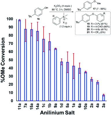
Applying our new mechanistic data, we examined the broader use of anilinium salts as methylating reagents. Degradation analysis revealed the range of thermal and additive stabilities (knowledge applicable to both cross coupling and process safety strategies). We hypothesised that those anilinium salts presenting as thermally unstable would, in turn, release methyl iodide in situ most readily, and also be more susceptible to direct nucleophilic attack, thus behaving as a viable methyl iodide replacement. For a comparative application in methylation, phenol O-alkylation was chosen as it remains one of the most used reactions in the pharmaceutical industry.68,69 4-tBu-Phenol (16) was selected as a suitable substrate for initial exploratory study. The conversion of 16 to 4-tBu-anisole (17) was calculated from the reaction mixture after 3 h via1H NMR spectroscopy, and the average conversion of each salt from triplicate experiments is shown in Fig. 17.From these experiments, the hypothesised trend of thermally unstable anilinium salts leading to more efficient methylation did not hold. Indeed, three of the most thermally unstable anilinium iodides 2a–4a and 15a – all carrying strong electron-withdrawing aryl substituents – led to measurable quantities of SNAr products (18–21) and poor yields of desired methylation products. Indeed, analysis of thermal degradation versus O-methylation efficiency within the anilinium salt library revealed that only those unstable salts bearing no resonance withdrawing aryl substituents served as efficient methylating reagents.
The anilinium iodide salt most reactive for methylation was shown to be 11a (3-Br), giving near-quantitative conversion to 16 with minimal variance (Fig. 18). We were surprised to see that salt 10a (3-Cl), which has a similar degradative profile to 11a (Fig. 5, 7 and 14), was considerably less reactive to methyl transfer under the applied conditions. More expectedly, 7a (4-Br) gave high conversions in comparison to the 5a (4-F) and 6a (4-Cl) analogues, the latter two presenting as more stable to thermal degradation. 14a (2-Me), the only salt identified as prone to degradation due to steric bulk, gave an average of 85 ± 11% conversion to the methylated product under the conditions tested. Salt 14a presents a viable alternative to 11a where methylation (or cross-coupling) reactions might be compromised by the presence of the 3-Br substituent in 11a. Surprisingly, 2a (2-Py), 3a (4-CHO), and 4a (4-Bz) anilinium iodide salts, each gave a relatively low conversion to 17 despite being the most thermally unstable salts in solution-phase. On closer inspection, it was found that SNAr products 18–20, were formed from use of the most resonance withdrawing anilinium iodide salts (Fig. 17). The SNAr reactivity presumably arises from 4-tBu-phenoxide displacing trimethylamine from the respective anilinium salt.6,65 Our own calculations remain consistent with the concerted SNAr mechanisms previously reported separately by DiMagno12 and Jacobsen.65 See the Computational analysis section (Fig. 23).
The trend in methylation ability for the halide salt series 1a–c correlated with extent of thermal degradation in solution, with the chloride salt giving higher conversions to methylated product than the analogous bromide and iodide salts. The triflate salt (1e) was comparative in methylating ability to the iodide salt (1a). Our mechanistic degradation studies showed that methyl iodide was produced upon heating the anilinium iodide salts in DMSO, raising the question of whether methylation of 16 occurs from reaction of the phenoxide nucleophile directly with the anilinium cation, from a methyl halide generated in situ, or both. The shared trend in anilinium degradation and phenol methylation reactivity (1c > 1b > 1a) suggests that decomposition to the methyl halide is important for reactivity. However, the comparable methylating ability of 1a (X = I) and 1e (X = OTf), despite the large difference in stability (see Fig. 9 and 13), indicates that attack directly onto the anilinium salt also occurs, assuming negligible degradation of the triflate salt to produce methyl triflate in situ (Fig. 11). We propose that a combination of direct reaction with the anilinium salts and indirect reaction (via methyl iodide generation) in the phenol methylation both occur under the reaction conditions employed. This proposal is further elaborated in discussion below.
To compare the effectiveness of methylating reagent 11a to common electrophilic methylating reagents, the methylation of phenol 16 was carried out using methyl iodide, methyl triflate, methyl tosylate, dimethylsulfate, and dimethylcarbonate under our chosen reaction conditions (Table 1).
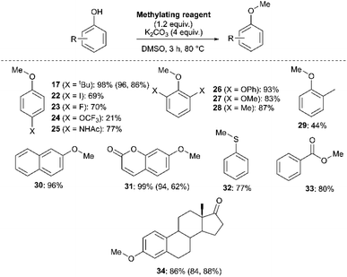
We next investigated the ability of 11a (3-Br) to methylate a range of phenols and related nucleophiles under our applied reaction conditions (Fig. 19, see Experimental ESI Section 20† for optimisation). A range of substituents and structural complexities around the phenol ring were tolerated in these methylation reactions, and most with good to excellent isolated yields (17, 22–31, 34). Additionally, thiophenol and benzoic acid could be methylated under the applied conditions to give thioether 32 and ester 33 with good 77% and 80% yields, respectively. Notably, having used the earlier mechanistic study to guide choice of reagent (Fig. 17), no SNAr product was observed in any of our reactions using 11a as a methylating reagent. 14a (2-Me) was explored as an alternative methylating reagent for cases where a 3-Br substituent could cause undesired reactivity, and was shown to be effective in the formation of 17 (86%), 31 (62%) and 34 (84%). Using the same subset of substrates, NMP was shown to be a viable alternative solvent, enabling the synthesis of 17, 31, and 34 in 96, 94, and 84% yield, respectively.
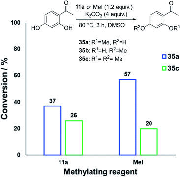
We also investigated whether or not 11a could provide any uniquely applicable regiochemical control when multiple nucleophilic phenol sites are present on a substrate. To probe this, 2′,4′-dihydroxyacetophenone was subjected to methylation with 11a and methyl iodide under our standard conditions, showing exploitable differences in reactivity and regioselectivity (Fig. 20). A deeper analysis of this synthetic application is the subject of future investigation.
Experimental mechanistic analysis of active methylation species in solution using anilinium salts
Having demonstrated the potential of N,N,N-trimethylanilinium (primarily iodide) salts to act as competent methylating reagents, we next aimed to understand the plausible mechanism(s) by which these O-methylation reactions occur. Our understanding of anilinium thermal degradation in DMSO-d6 suggested multiple possible methylation pathways: Path A: from methyl iodide generated from TMSO–I degradation, Path B: from TMSO–I that forms in situ through methylation of the non-innocent DMSO solvent by methyl iodide, Path C: via methyl iodide generated from the anilinium iodide degradation, and Path D: direct attack of the nucleophile onto an N-methyl group of the anilinium cation (Fig. 21).To address the question of whether or not substrate methylation comes solely from the anilinium degradation-led generation of methyl iodide (Path C), we carried out the methylation of 16 under our chosen (loosely-optimised) reaction conditions using 3-bromo-N,N,N-trimethylanilinium PF6 (11d) and BArF (11f) salts (Table 2). In these reactions where methyl iodide could not be generated, 17 was formed in 45% (entry 2) and 50% (entry 3) yield, compared to 98% yield when using iodide salt 11a (entry 1). This showed that the generation of methyl iodide likely accompanies efficient methylation of phenoxide substrates, but is not a necessity for the reaction to occur under the chosen conditions. Given the knowledge that anilinium PF6 and BArF salts can partially decompose in DMSO-d6 to give the TMSO cation (see Fig. 11), it is possible that methylation could occur in these reactions from the anilinium directly (Path D) or the TMSO cation itself (Path B).
To investigate this further, we ran the same methylation reactions with TMSO salts in the place of anilinium salts. TMSOI formed 17 in 76% yield (entry 4). We were able to demonstrate through NMR analysis that TMSOI decomposes thermally to give DMSO and methyl iodide at 80 °C, the reverse reaction was also shown to occur (Experimental ESI Section 22†). This finding raised the question as to whether TMSO+ acts directly as a source of methyl group (Path B), or if the methylation is simply occurring from methyl iodide produced via its thermal decomposition (Path A). TMSO–PF6 and TMSO–BArF were synthesised and subsequently used in methylation reactions to afford the anisole 17 in 57% (entry 5) and 53% yield (entry 6), respectively. While this suggests that the TMSO+ cation is capable of methylating phenols, it does not rule out the possibility that nucleophiles can directly attack the anilinium cation to form the methylated product (Path D). To investigate the ability of the anilinium cation to directly methylate the substrate, the ability to generate TMSO+ in the reaction mixture would also have to be removed. Accordingly, we ran the methylation reactions in N-methyl-2-pyrrolidone (NMP). Anilinium iodide 11a was used to methylate 16, giving 88% of the methylated product (entry 7).
We then repeated the reaction using anilinium PF6 salt 11d as the methylating reagent, which gave only 11% yield of 17, strongly suggesting that the degradation of the anilinium iodide to release methyl iodide in situ is a key contributor to the reaction (Path C); computational studies reveal that the barriers for degradation and direct reaction are close such that reaction flux through each pathway likely depends on the details of concentration, temperature and the identity of the anilinium salt. Furthermore, additive experiments (entries 9 and 10) probing the presence of radical-centred degradation and methylation mechanisms were carried out. These data remained consistent with experimental and theoretical evidence that anilinium iodide degradation was primarily via closed shell pathways, and that the principle self-immolative degradation pathway was faster than degradation via DMSO participation (see Fig. 9, 11 and 12).
Computational analysis of anilinium salt degradation and methylation mechanisms
Further mechanistic insight for both anilinium salt degradation and methylation was sought from computational studies. The computations were all performed at the M06-2X/6-31+G** level of theory and with IEF-PCM for DMSO as the solvation model, all performed in Gaussian09.70 M06-2X was designed to be a preferred method for the investigation of reaction barriers, and so is appropriate for this task. Vibrational and standard state corrections were implemented using Goodvibes (with concentration values 1 M and 14.1 M respectively for solutes and DMSO; a frequency cut-off of 100 cm−1 was used).71 In exploring competition between first and second order reactions, the role of specific interactions between solvent and solute was explored by placing DMSO molecules such that their oxygen was in positions expected to be favoured for such interactions, namely: between the methyl groups of anilinium or TMSO, between the ortho-hydrogens and the methyl groups of an anilinium, and, in the case of 3a (4-CHO), adjacent to the formyl hydrogen with methyl groups of the DMSO solvent molecules placed so as to interact with the carbonyl group. The lowest free energy guides selection of the preferred solvation geometry (and explicit solvent molecules are excluded when they involve an increase in free energy). The solvation free energy of DMSO itself (in either implicit or explicit solvation regimes) is assumed to be approximately 0 kJ mol−1 in line with the thermodynamic analysis of Lai et al. and so gas phase values are employed.72 The details of all calculations are provided in the Computational ESI.† Generally, the implicit solvation calculations are reported unless noted.A key first step was to establish the likely speciation of the anilinium salts, as either separated ions and/or as ion pairs. The latter was supported by our DOSY NMR measurements (Experimental ESI Section 13†). Two geometries were considered for the ion-pair, one with the halide placed as an extension of the ipso-Caromatic–N bond, and the other with the halide between the N-methyl groups and the ortho C–H position. The latter was found to be energetically preferred in all cases investigated (see Computational ESI Section 2†). Calculations at 353 K (80 °C) predicted all of the iodide salts to have a small (3–16 kJ mol−1, or 0.8–3.8 kcal mol−1) preference to be ion-paired (see Computational ESI Section 5†). The bromides are computed to have a mix of preferences, with 4-CHO and 3-Br showing ∼2 kJ mol−1 (or ∼0.5 kcal mol−1) preferences to be ion pairs, while 2-Me and 2-pyridyl show preferences to be separate ions. Chloride salts were computed to all have an energetic preference of 0.8–11.7 kJ mol−1 (or 0.2 to 2.8 kcal mol−1) to be separated ions apart from for 3-Cl and 3-Br.
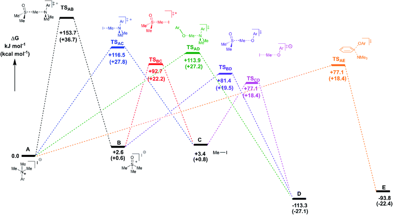
Reaction profiles were computed for each of the anilinium salts in which both degradative reactions (MeI formation and reaction with solvent) and productive reactions (SN2 and SNAr with phenolate) are compared. An example is given for 3a in Fig. 22 where:
State A = the reactant anilinium salt (as an ion-pair)
State B = methyl transfer to solvent DMSO
State C = self-immolative methyl transfer to halide (i.e. MeI is formed)
State D = SN2 methylation of phenolate, and
State E = SNAr reaction.
Some features are consistent for each of the iodide salts. First, the reaction of the anilinium iodide with DMSO is kinetically and significantly disfavoured (Fig. 22, A → B). The formation of MeI (Fig. 22, A → C) is close to thermoneutral and has a barrier that is readily accessible at the elevated temperatures employed in the experimental studies. Electron donating groups disfavour formation of MeI. The reverse reaction in which anilinium reforms is also accessible. The barrier for methyl iodide to react with DMSO is 89.3 kJ mol−1 (or 21.3 kcal mol−1). These calculations are consistent with the observed delay in sulfoxonium formation coming only after methyl iodide formation, the intermediate formation of both methyl iodide and sulfoxonium, the induction period in the observed formation of DMSO-d3, and the observed positions of H/D scrambling (Fig. 12).
The reactions with phenolate, SN2 (Fig. 22, C → D) and SNAr (Fig. 22, A → E) have barriers that are low and largely irreversible. For salts 2a (2-Pyr), 3a (4-CHO), and 4-Bz (4a), the barrier for SNAr is computed to be the most lowered versus SN2 (Fig. 23), qualitatively corresponding to the observation of SNAr product dominating the product mixture (Fig. 18). More electron-donating substituents are computed to have a preference for SN2 but this is accompanied by an overall higher barrier for reaction; thus, iodide salts predicted to be selective for methylation over arylation are also predicted to react more slowly. Although the 4-CHO salt (3a) has barriers for direct reaction of phenolate with salt that are significantly lower than those for formation of MeI (77.7 kJ mol−1 for SNAr vs. 116.5 kJ mol−1 for SN2), this is not the case for all anilinium salts universally. For instance, the unsubstituted iodide salt, 1a (Computational ESI Section 3†), is computed to have a barrier to formation of MeI of 125.2 kJ mol−1 (29.9 kcal mol−1), a barrier to SNAr of 124.6 kJ mol−1 (29.8 kcal mol−1), and a barrier to SN2 with phenoxide of 120.4 kJ mol−1 (28.8 kcal mol−1), and thus all three processes might be expected to be operating experimentally. While the calculations are not able to explicitly corroborate 11a (3-Br) as the experimentally optimum methylating reagent, they are suggestive of this salt as having a good balance between the likely degree of degradation and the selectivity between SN2 and SNAr reactions, thus providing an effective and safer ‘slow bleed’ alternative to methyl iodide.
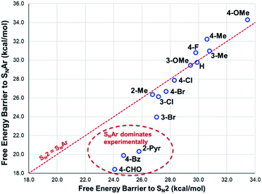 | ||
| Fig. 23 DFT-computed comparison of SNAr and SN2 barriers for reaction of phenolate with anilinium cation. Method: M06-2X/6-31+G**/IEFPCM (DMSO). T = 353.15 K (80 °C). | ||
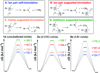
Fig. 24 shows three alternative modes of anilinium iodide self-immolation in ion-pairs, beyond the simple first order self-reaction, that were all considered computationally. In this case, explicit DMSO molecules were included around the anilinium (or formyl groups in 3a) for any instances where such explicit solvation was computed to have a negative free energy of association. Of all 4 mechanisms of degradation (A–D), A and C were consistently calculated to be the most accessible across calculations involving salts 1a, 3a, and 11a; thus, at high concentrations and at 80 °C, second order contributions to anilinium iodide degradation are computed to be accessible. This is consistent with the observed deviation from linear concentration dependence reported in Fig. 15. At first sight, this suggestion appears inconsistent with the lack of sensitivity to addition of excess iodide revealed in Fig. 9. However, it should be kept in mind that the temperature dependence of the second order reactions (that involve the entropic penalty of bringing together two reactants) will be markedly different from that for the first order reaction. The calculations support a remarkably fine balance between a number of alternative modes of reactivity that can be selected between with careful choice of concentrations, temperatures, and reagents.
Limitations of mechanistic analysis
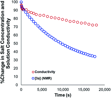
Our mechanistic analysis – both experimental and computational – is consistent with at least two operative mechanisms of anilinium iodide degradation. The first and most dominant is simple first order self-immolation; one ion-pair degrades to one molecule of dimethylaniline and one molecule of methyl iodide. The second mechanism, accessible at higher concentrations of anilinium iodide, is proposed to be (at least in part) second order with respect to the anilinium iodide ion pair. Further microkinetic analysis remains consistent with both first and second order processes being operative (see Experimental ESI Section 17†). The main unavoidable assumption in all mechanistic analysis, is that these reactions proceed in an unchanging medium that presents unchanging physical properties as the main reactions proceed. In reality, an unchanging medium is highly unlikely, especially for such reactions proceeding from charged reactants to neutral products. Conductivity measurements (Fig. 25, and Experimental ESI Section 25†) and scans of solvent model dielectric constant versus ΔG (Computational ESI, Section 5†) show that the physical properties of the reaction medium change with time. The temperature variation of the nature of both the medium and the solvation thermodynamics are also unlikely to be universally consistent for the different structural variations of anilinium iodide. As a result of the identified subtleties of these very commonly applied DFT methods, this investigation also provides a powerful data set on ionic reactivity that can actively inform new computational approaches to studying the impact of solvent and counterions on reactivity.73Conclusions
We have presented solid and solution phase thermal degradation analyses, kinetic studies, isotopic labelling, and computational modelling showing that N,N,N-trimethylanilinium salts are likely to degrade in a self-destructive process. Taken together, the mechanistic experiments forced a partial revision of our initial mechanistic hypothesis from Fig. 13, as displayed in Fig. 26. Increasing the anilinium counter-anion nucleophilicity, solution concentration, electron-withdrawing aryl substituent power, soluble non-iodide halides, and solution temperature were all found to increase the rate of salt degradation. The minimal impact of solvent-led degradation pathways was supported by computational modelling of the two degradation pathways. A range of N,N,N-trimethylanilinium salts was tested as O-methylation reagents, with aryl-substitution and counterion species shown to affect methylating ability. 3-Br-N,N,N-Trimethylanilinium iodide (11a) was shown to be an effective methylating reagent for a variety of phenols in DMSO and NMP. Mechanistic studies suggest that in situ generated methyl iodide is likely to be the main methylating reagent in these reactions. From a practical standpoint, should these anilinium salts be made accessible without first using methyl iodide, we thus envisage that carefully selected anilinium iodide salt could function as a safer, crystalline, and storable ‘slow bleed’ alternative to using carcinogenic and low-boiling methyl iodide directly.42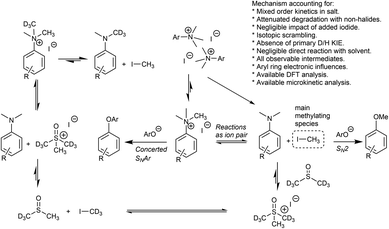 | ||
| Fig. 26 Revised mechanistic model for anilinium iodide degradation, consistent with all available experimental and computational mechanistic evidence. | ||
The same studies have highlighted the most stable anilinium salt configurations, and those salts for which concerted SNAr at the ipso carbon of the parent anilinium salts presents dominant reactivity, both key considerations for chemists aiming to exploit these same salts for cross-coupling as opposed to methylation reactivity.
Beyond advancing popular O-alkylation strategies,69 it is clear that varied applications of trimethylammonium salts is, at the time of writing, on the rise.74 As such, the implications of the above results on a broader range of chemistries involving trimethylanilinium salts is also worth delineating. In our estimation, the fundamental understanding of the structural parameters affecting anilinium salt degradation hold implications for: (i) the design of anilinium-derived ionic liquids used as solvents, electrolytes, and in electropolymerisation strategies,75,76 (ii) the design and understanding of anilinium-derived compounds used in antibacterial technologies,77,78 (iii) understanding the reaction conditions and range of anilinium substitution patterns amenable to metal-catalysed chemistries (including but not limited to arylation, alkynylation, silylation, and ortho-methylation),7,8,23,29,31,79 (iv) understanding substrate design for 18F radiolabelling mediated by SNAr chemistries on anilinium cores,12,80 and (v) a fuller understanding of the range of anilinium structures applicable to ion-pair directed regiocontrol of C–H activation methods.2
Author contributions
JBW – data curation; formal analysis; investigation; methodology; validation; visualization; writing – original draft. MA – data curation; formal analysis; investigation; methodology; validation; visualization; writing – original draft. CY – data curation; formal analysis; investigation; methodology; validation; visualization. DM – data curation; formal analysis; investigation; methodology; validation; visualization. VJ – data curation; investigation; visualization. AGL – supervision; data curation; formal analysis; investigation; methodology; validation; writing – original draft; writing – review & editing. SEB – supervision; writing – review & editing. MR – conceptualization; formal analysis; project administration; supervision; validation; writing – original draft; writing – review & editing.Conflicts of interest
There are no conflicts to declare.Acknowledgements
MR thanks the Leverhulme Trust for fellowship funding (ECF-2016-264). JBW thanks GlaxoSmithKline for funding. MR, DM, CY, and JBW thank Drs John Liggat and Len Berlouis for helpful discussions during the course of solid-state thermal degradation investigations. MR thanks the ARCHIE-WeSt High Performance Computer service (www.archie-west.ac.uk) based at the University of Strathclyde. MR and JBW thank the EPSRC for funding via Prosperity partnership EP/S035990/1. AGL and MA would like to acknowledge AstraZeneca for funding, and also the assistance given by Research IT and the use of the Computational Shared Facility at The University of Manchester.Notes and references
- S. E. Denmark, N. D. Gould and L. M. Wolf, J. Org. Chem., 2011, 76, 4260–4336 CrossRef CAS PubMed.
- H. J. Davis, M. T. Mihai and R. J. Phipps, J. Am. Chem. Soc., 2016, 138, 12759–12762 CrossRef CAS PubMed.
- K. Brak and E. N. Jacobsen, Angew. Chem., Int. Ed., 2013, 52, 534–561 CrossRef CAS PubMed.
- N. A. Shamsutdinova, I. D. Strelnik, E. I. Musina, T. P. Gerasimova, S. A. Katsyuba, V. M. Babaev, D. B. Krivolapov, I. A. Litvinov, A. R. Mustafina, A. A. Karasik and O. G. Sinyashin, New J. Chem., 2016, 40, 9853–9861 RSC.
- P. H. J. Carlsen, K. Liberkova, R. Harrex, J. Røe, K. Rissanen, W. Shi, S. Styring, C. Tommos, K. Warncke and B. R. Wood, Acta Chem. Scand., 1997, 51, 343–344 CrossRef CAS.
- D. Wang, Z. Yang, C. Wang, A. Zhang and M. Uchiyama, Angew. Chem., Int. Ed., 2018, 57, 3641–3645 CrossRef CAS PubMed.
- D. Y. Wang, X. Wen, C. D. Xiong, J. N. Zhao, C. Y. Ding, Q. Meng, H. Zhou, C. Wang, M. Uchiyama, X. J. Lu and A. Zhang, iScience, 2019, 15, 307–315 CrossRef CAS PubMed.
- T. Uemura, M. Yamaguchi and N. Chatani, Angew. Chem., Int. Ed., 2016, 55, 3162–3165 CrossRef CAS PubMed.
- E. Wenkert, A.-L. Han and C.-J. Jenny, J. Chem. Soc., Chem. Commun., 1988, 975–976 RSC.
- J. T. Reeves, D. R. Fandrick, Z. Tan, J. J. Song, H. Lee, N. K. Yee and C. H. Senanayake, Org. Lett., 2010, 12, 4388–4391 CrossRef CAS PubMed.
- S. B. Blakey and D. W. C. MacMillan, J. Am. Chem. Soc., 2003, 125, 6046–6047 CrossRef CAS PubMed.
- H. Sun and S. G. DiMagno, J. Fluorine Chem., 2007, 128, 806–812 CrossRef CAS.
- N.-U. H. Khan, B. C. Lee, S.-Y. Lee, Y. S. Choe, C.-H. Jun and D. Y. Chi, J. Labelled Compd. Radiopharm., 2002, 45, 1045–1053 CrossRef CAS.
- R. Richarz, P. Krapf, F. Zarrad, E. A. Urusova, B. Neumaier and B. D. Zlatopolskiy, Org. Biomol. Chem., 2014, 12, 8094–8099 RSC.
- X. Huang, R. J. Gillies and H. Tian, J. Labelled Compd. Radiopharm., 2015, 58, 156–162 CrossRef CAS PubMed.
- G. F. Silbestri, M. T. Lockhart and A. B. Chopra, ARKIVOC, 2011, 210–220 Search PubMed.
- Y.-T. Wang, B.-B. Gao, F. Wang, S.-Y. Liu, H. Yu, W.-H. Zhang and J.-P. Lang, Dalton Trans., 2017, 46, 1832–1839 RSC.
- B.-B. Gao, M. Zhang, X.-R. Chen, D.-L. Zhu, H. Yu, W.-H. Zhang and J.-P. Lang, Dalton Trans., 2018, 47, 5780–5788 RSC.
- J. Martínez, F. de la Cruz-Martínez, M. A. Gaona, E. Pinilla-Peñalver, J. Fernández-Baeza, A. M. Rodríguez, J. A. Castro-Osma, A. Otero and A. Lara-Sánchez, Inorg. Chem., 2019, 58, 3396–3408 CrossRef PubMed.
- S. P. Desai, M. Mondal and J. Choudhury, Organometallics, 2015, 34, 2731–2736 CrossRef CAS.
- F. Sadegh, O. Bagheri, M. Moghadam, V. Mirkhani, S. Tangestaninejad and I. Mohammadpoor-Baltork, J. Organomet. Chem., 2014, 759, 46–57 CrossRef CAS.
- A. Chen, G. Er, C. Zhang, J. Tang, M. Alam, H. T. Ta, A. G. Elliott, M. A. Cooper, J. Perera, S. Swift, I. Blakey, A. K. Whittaker and H. Peng, J. Polym. Sci., Part A: Polym. Chem., 2019, 57, 1908–1921 CrossRef CAS.
- A. W. Rand and J. Montgomery, Chem. Sci., 2019, 10, 5338–5344 RSC.
- Y. I. Park, O. Postupna, A. Zhugayevych, H. Shin, Y.-S. Park, B. Kim, H.-J. Yen, P. Cheruku, J. S. Martinez, J. W. Park, S. Tretiak and H.-L. Wang, Chem. Sci., 2015, 6, 789–797 RSC.
- Y. Ma, L. Zhang, Y. Luo, M. Nishiura and Z. Hou, J. Am. Chem. Soc., 2017, 139, 12434–12437 CrossRef CAS PubMed.
- Q. Chen, F. Gao, H. Tang, M. Yao, Q. Zhao, Y. Shi, Y. Dang and C. Cao, ACS Catal., 2019, 9, 3730–3736 CrossRef CAS.
- L. G. Xie and Z. X. Wang, Angew. Chem., Int. Ed., 2011, 50, 4901–4904 CrossRef CAS PubMed.
- Z.-X. Wang and B. Yang, Org. Biomol. Chem., 2020, 18, 1057–1072 RSC.
- C. Wang, Chem. Pharm. Bull., 2020, 68, 683–693 CrossRef CAS PubMed.
- H. Chen, H. Yang, N. Li, X. Xue, Z. He and Q. Zeng, Org. Process Res. Dev., 2019, 23, 1679–1685 CrossRef CAS.
- L. Liu, W.-Q. Yu, T. Huang and T. Chen, Tetrahedron Lett., 2020, 61, 151647 CrossRef CAS.
- B. W. H. Turnbull, J. Chae, S. Oliver and P. A. Evans, Chem. Sci., 2017, 8, 4001–4005 RSC.
- X.-Q. Zhang and Z.-X. Wang, J. Org. Chem., 2012, 77, 3658–3663 CrossRef CAS PubMed.
- J. Hu, H. Sun, W. Cai, X. Pu, Y. Zhang and Z. Shi, J. Org. Chem., 2016, 81, 14–24 CrossRef CAS PubMed.
- H. Zhang, S. Hagihara and K. Itami, Chem.–Eur. J., 2015, 21, 16796–16800 CrossRef CAS PubMed.
- X.-Q. Zhang and Z.-X. Wang, Org. Biomol. Chem., 2014, 12, 1448–1453 RSC.
- F. Zhu, J.-L. Tao and Z.-X. Wang, Org. Lett., 2015, 17, 4926–4929 CrossRef CAS PubMed.
- R. W. Hoffmann, Angew. Chem., Int. Ed., 2000, 39, 2054–2070 CrossRef PubMed.
- M. Burns, S. Essafi, J. R. Bame, S. P. Bull, M. P. Webster, S. Balieu, J. W. Dale, C. P. Butts, J. N. Harvey and V. K. Aggarwal, Nature, 2014, 513, 183–188 CrossRef CAS PubMed.
- H. Schönherr and T. Cernak, Angew. Chem., Int. Ed., 2013, 52, 12256–12267 CrossRef PubMed.
- E. J. Barreiro, A. E. Kümmerle and C. A. M. Fraga, Chem. Rev., 2011, 111, 5215–5246 CrossRef CAS PubMed.
- M. Butters, D. Catterick, A. Craig, A. Curzons, D. Dale, A. Gillmore, S. P. Green, I. Marziano, J.-P. Sherlock and W. White, Chem. Rev., 2006, 106, 3002–3027 CrossRef CAS PubMed.
- K. Endo and T. Shibata, Synthesis, 2012, 44, 1427–1452 CrossRef CAS.
- J. Kim and S. H. Cho, Synlett, 2016, 27, 2525–2529 CrossRef CAS.
- R. Giri, S. Thapa and A. Kafle, Adv. Synth. Catal., 2014, 356, 1395–1411 CrossRef CAS.
- G. Lamoureux and C. Agüero, ARKIVOC, 2009, 2009, 251–264 Search PubMed.
- J. Macgee, J. Anal. Chem., 1970, 42, 421–422 CAS.
- D. G. Bailey, J. Chromatogr., 1975, 11, 305–311 Search PubMed.
- L. Hevesi, Tetrahedron Lett., 1976, 17, 1389–1390 CrossRef.
- J. L. Day, P. Grenier and L. Harold, J. Chromatogr. A, 1979, 177, 118–121 CrossRef CAS.
- J. Hartenstein and E. Fritschi, US Pat., US4425350A, 1980 Search PubMed.
- C. A. Francis, US Pat., US20050261500A1, 2004 Search PubMed.
- G. Noonan and A. G. Leach, Org. Biomol. Chem., 2015, 13, 2555–2560 RSC.
- A. L. Dunn, A. Payne, P. R. Clark, C. McKay, G. D. Williams, K. Wheelhouse, K. Arendt, F. Dixon and S. Shilcrat, J. Chem. Educ., 2021, 98, 175–182 CrossRef CAS.
- J. P. Lewicki, D. Todd, P. Redon, J. Liggat and L. Gibson, MRS Online Proc. Libr., 2007, 1047, 1047-Y04-05 CrossRef.
- E. Avella-Moreno, N. Nuñez-Dallos, L. Garzón-Tovar and A. Duarte-Ruiz, J. Sulfur Chem., 2015, 36, 535–543 CrossRef CAS.
- Z. Shen, S. Zhang, H. Geng, J. Wang, X. Zhang, A. Zhou, C. Yao, X. Chen and W. Wang, Org. Lett., 2019, 21, 448–452 CrossRef CAS PubMed.
- Y. Chen, Chem.–Eur. J., 2019, 25, 3405–3439 CrossRef CAS PubMed.
- P. Storoniak and J. Rak, J. Therm. Anal. Calorim., 2000, 60, 927–941 CrossRef.
- R. F. Rodewald, K. Mahendran, J. L. Bear and R. Fuchs, J. Am. Chem. Soc., 1968, 90, 6698–6700 CrossRef CAS.
- W. M. Weaver and J. D. Hutchison, J. Am. Chem. Soc., 1964, 86, 261–265 CrossRef CAS.
- P. S. Pregosin, Magn. Reson. Chem., 2017, 55, 405–413 CrossRef CAS PubMed.
- E. V. Dalessandro and J. R. Pliego, Theor. Chem. Acc., 2020, 139, 27 Search PubMed.
- E. M. Arnett and D. R. McKelvey, J. Am. Chem. Soc., 1966, 88, 2598–2599 CrossRef CAS.
- E. E. Kwan, Y. Zeng, H. A. Besser and E. N. Jacobsen, Nat. Chem., 2018, 10, 917–923 CrossRef CAS PubMed.
- C. Gardner Swain and E. C. Lupton, J. Am. Chem. Soc., 1968, 90, 4328–4337 CrossRef.
- J. T. Burns and K. T. Leffek, Can. J. Chem., 1969, 47, 3725–3728 CrossRef CAS.
- S. D. Roughley and A. M. Jordan, J. Med. Chem., 2011, 54, 3451–3479 CrossRef CAS PubMed.
- D. G. Brown and J. Boström, J. Med. Chem., 2016, 59, 4443–4458 CrossRef CAS PubMed.
- M. J. Frisch, G. W. Trucks, H. B. Schlegel, G. E. Scuseria, M. A. Robb, J. R. Cheeseman, G. Scalmani, V. Barone, B. Mennucci, G. A. Petersson, H. Nakatsuji, M. Caricato, X. Li, H. P. Hratchian, A. F. Izmaylov, J. Bloino, G. Zheng, J. L. Sonnenberg, M. Hada, M. Ehara, K. Toyota, R. Fukuda, J. Hasegawa, M. Ishida, T. Nakajima, Y. Honda, O. Kitao, H. Nakai, T. Vreven, J. J. A. Montgomery, J. E. Peralta, F. Ogliaro, M. Bearpark, J. J. Heyd, E. Brothers, K. N. Kudin, V. N. Staroverov, R. Kobayashi, J. Normand, K. Raghavachari, A. Rendell, J. C. Burant, S. S. Iyengar, J. Tomasi, M. Cossi, N. Rega, J. M. Millam, M. Klene, J. E. Knox, J. B. Cross, V. Bakken, C. Adamo, J. Jaramillo, R. Gomperts, R. E. Stratmann, O. Yazyev, A. J. Austin, R. Cammi, C. Pomelli, J. W. Ochterski, R. L. Martin, K. Morokuma, V. G. Zakrzewski, G. A. Voth, P. Salvador, J. J. Dannenberg, S. Dapprich, A. D. Daniels, O. Farkas, J. B. Foresman, J. V. Ortiz, J. Cioslowski and D. J. Fox, 2009.
- G. Luchini, J. V. Alegre-Requena, I. Funes-Ardoiz and R. S. Paton, F1000Research, 2020, 9, 291 Search PubMed.
- J. T. W. Lai, F. W. Lau, D. Robb, P. Westh, G. Nielsen, C. Trandum, A. Hvidt and Y. Koga, J. Solution Chem., 1995, 24, 89–102 CrossRef CAS.
- Y. Nieves-Quinones and D. A. Singleton, J. Am. Chem. Soc., 2016, 138, 15167–15176 CrossRef CAS PubMed.
- A conservative Scopus search of 1610 chemistry-focussed research articles containing “trimethylammonium” in the title and/or abstract shows an increase of 40 articles per year to over 100 articles per year in the period 2000–20.
- M. E. Abdelhamid, T. Murdoch, T. L. Greaves, A. P. O'Mullane and G. A. Snook, Phys. Chem. Chem. Phys., 2015, 17, 17967–17972 RSC.
- B. Baker, C. J. Cockram, S. Dakein, J. M. DeMaria, D. M. George, K. R. Malyk, M. J. F. Sarno and A. J. P. Cardenas, J. Mol. Struct., 2021, 1225, 129122 CrossRef CAS.
- S. Chakraborty, R. Barman and S. Ghosh, J. Mater. Chem. B, 2020, 8, 2909–2917 RSC.
- O. Bulut, H. A. Oktem and M. D. Yilmaz, J. Hazard. Mater., 2020, 399, 122902 CrossRef CAS PubMed.
- D.-Y. Wang, K. Morimoto, Z. Yang, C. Wang and M. Uchiyama, Chem.–Asian J., 2017, 12, 2554–2557 CrossRef CAS PubMed.
- C. N. Neumann, J. M. Hooker and T. Ritter, Nature, 2016, 534, 369–373 CrossRef CAS PubMed.
Footnote |
| † Electronic supplementary information (ESI) available. See DOI: 10.1039/d1sc00757b |
| This journal is © The Royal Society of Chemistry 2021 |

