DOI:
10.1039/D0SC06894B
(Review Article)
Chem. Sci., 2021,
12, 7623-7655
State-of-the-art anodes of potassium-ion batteries: synthesis, chemistry, and applications
Received
18th December 2020
, Accepted 4th May 2021
First published on 11th May 2021
Abstract
The growing demand for green energy has fueled the exploration of sustainable and eco-friendly energy storage systems. To date, the primary focus has been solely on the enhancement of lithium-ion battery (LIB) technologies. Recently, the increasing demand and uneven distribution of lithium resources have prompted extensive attention toward the development of other advanced battery systems. As a promising alternative to LIBs, potassium-ion batteries (KIBs) have attracted considerable interest over the past years owing to their resource abundance, low cost, and high working voltage. Capitalizing on the significant research and technological advancements of LIBs, KIBs have undergone rapid development, especially the anode component, and diverse synthesis techniques, potassiation chemistry, and energy storage applications have been systematically investigated and proposed. In this review, the necessity of exploring superior anode materials is highlighted, and representative KIB anodes as well as various structural construction approaches are summarized. Furthermore, critical issues, challenges, and perspectives of KIB anodes are meticulously organized and presented. With a strengthened understanding of the associated potassiation chemistry, the composition and microstructural modification of KIB anodes could be significantly improved.
1. Introduction
Since the successful commercialization of Li-ion batteries (LIBs) by Sony Corporation in 1991, LIBs have gradually attracted considerable attention worldwide over the past 29 years, merging high energy density, compact and lightweight designs, and acceptable cycle life.56,57 In recent years, with the gradual advancement of practical battery technology, LIBs have become the dominating power sources for portable electronics and electric vehicles, and are regarded as a promising technology for stationary and large-scale electrical energy storage grids, which have been historically dominated by pumped-hydro technology (over 95% of the total rated power) according to the global energy storage database from the United States Department of Energy.87,88 Nevertheless, the prevailing deficiency and uneven distribution of lithium resources worldwide have resulted in increasing concern regarding the high reliance on the mass production of LIBs; thus, alternative batteries based on earth-abundant elements have been receiving immense attention.107,108 Owing to the abundance and similar electrochemical properties as those of lithium, the application of potassium is being intensively investigated. As the seventh most abundant element in the Earth's crust, the cost of potassium-ion batteries (KIBs) is relatively reasonable.115 Additionally, potassium, the next alkali metal after sodium in the periodic table, has a lower reduction potential (−2.93 V vs. standard hydrogen electrode) than that of sodium (−2.71 V vs. standard hydrogen electrode) (Fig. 1a),127,128 thereby enabling KIBs to operate at a relatively higher potential. As potassium can be utilized as a charge carrier that shuttles from the anode to the cathode, similar to the alkali metal ions in LIBs, KIBs can be fabricated in a “rocking-chair”-type manner.132 In addition, potassium–sulfur (K–S) and potassium–oxygen (K–O2) batteries have been considered as potential rechargeable batteries owing to their reasonable cost and impressive theoretical energy density. Like Li–S and Li–O2 batteries, K–S and K–O2 batteries have an enhanced capability to accommodate a higher number of ions and electrons through conversion reactions; nevertheless, the potassium storage behavior remains controversial owing to the limited amount of studies on K–S and K–O2 batteries.133 Notably, research on potassium-based batteries has recently attracted extensive attention within the scientific community, which can be gauged by the rapid increase in the number of publications related to these batteries.135 Investigations on K–S and K–O2 batteries are still in the early stages, whereas studies on KIBs are already sufficient to provide a comprehensive summary (Fig. 1b and c).
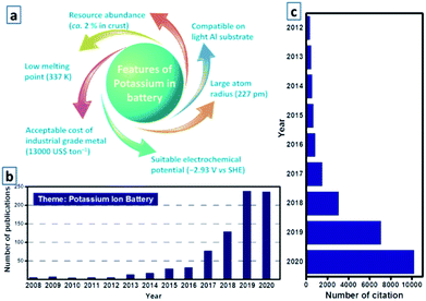 |
| | Fig. 1 (a) Various features of potassium in batteries. (b) Literature distribution of KIB based research from 2008 to 2020 in the website of Web of Science, and (c) corresponding number of citations. | |
Among all the KIB components, the anode active materials have similar storage behaviors as those in LIB anodes; thus, most researchers commence their investigations by studying the electrochemical properties of KIB anodes. For instance, graphite, as a standard anode in commercial LIBs, has been investigated as a host for K-ion storage, and it provides feasible accommodation for K-ion insertion and extraction at an operating potential of approximately 0.1 V. In addition, with the reversible formation of KC8, it can provide a theoretical reversible capacity of 278 mA h g−1.138 Beyond conventional graphite, the electrochemistry of other unique anodes has also been significantly explored. After the rational construction of the microstructure of anodes, which significantly enhance potassium storage, desirable cycling performances have been successfully achieved.139 Nevertheless, several bottlenecks need to be addressed before their further application. For example, although graphitic anodes have relatively low and flat voltage plateaus, their potassium storage capability is generally insufficient due to the large size of K ions. An alloying active material possesses high capacity but always suffers from severe volume change, and the initial coulombic efficiency in non-graphitic carbon anodes is usually undesirable and requires rational improvement. To date, various material engineering strategies combined with different electrode designs have been proposed to address these limitations in a targeted manner. An intensive summary of the current research status of various KIB anodes is essential to elucidate the current development of KIB anodes, as well as to provide constructive guidance for more purposeful research in the near future.
In this review, we present the recent achievements of KIB anode materials, focusing on their synthesis chemistry, potassium storage behavior, electrochemical performance, and contemporary bottlenecks (Fig. 2). Based on the extensive summary and analysis, we discuss perspectives for further exploration of new KIB anode materials.
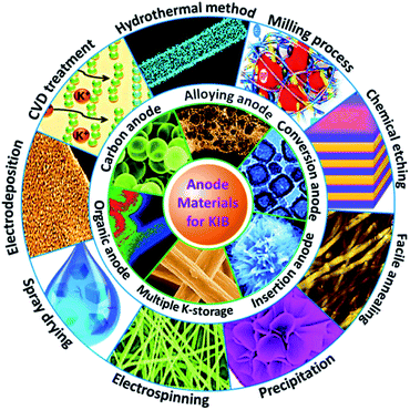 |
| | Fig. 2 Overview of the preparation and application of various KIB anodes. | |
2. Strategies and methods
2.1 Hydrothermal treatment
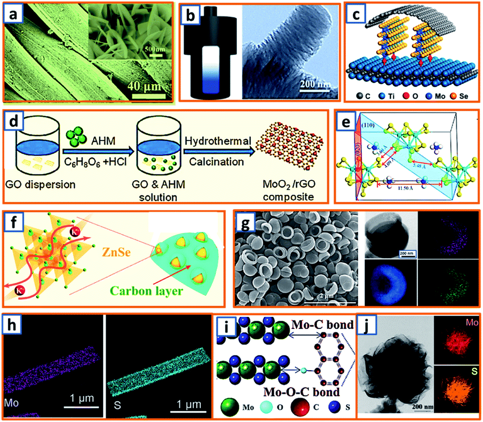
Hydrothermal reactions provide a cost-effective and environmentally friendly strategy to efficiently synthesize products with high phase purity, optimized morphology, and controlled particle size distribution.142–144 This strategy has been duly applied for the synthesis of anode materials with unique microstructures and desired sizes for utilization in KIBs. For instance, Wang et al. directly prepared SnO2 nanosheets (NSs) grown on stainless steel mesh (SSM) as electrodes for potassium storage through a hydrothermal process, wherein the ultrasonically cleaned SSM was immersed into a SnCl2 solution before being placed into a Teflon-lined stainless steel autoclave.3 After heat treatment at 200 °C, large SnO2 NSs with a size of approximately 800 nm were identified on the SSM surface (Fig. 3a). During the hydrothermal process, water participated in the generation of anode porosity and structural orientation. To address the slow kinetics and large volume expansion during potassiation, a high-oriented mesoporous graphitic carbon nanospring was prepared by Qian et al. using hydrothermal epoxy resin (Fig. 3b).30 First, a large amount of macromolecules was formed through the thermal polymerization of epoxy resin. Then, a one-dimensional (1D) structure was formed owing to its low supersaturation in water. Finally, at high temperatures, the carbon nanorod expanded along the axial direction to form a nanospring-like structure due to the [002] orientation, which is beneficial for the migration path of potassium ions and enhancement of rate capability. Besides, hierarchical carbon-coated MoSe2/MXene hybrid NSs (MoSe2/MXene@C) were presented by Huang et al. through the hydrothermal treatment of a mixture of Se in N2H4 solution, and Ti3C2Tx MXene in Na2MoO4 solution for 12 h, during which MoSe2 NSs were anchored on MXene flakes through strong covalent bonds.44 After applying a polydopamine (PDA) coating, it was annealed in a H2/Ar atmosphere to realize a uniform carbon layer, thereby effectively reinforcing the hierarchical two-dimensional (2D) nanostructure and enhancing the overall conductivity (Fig. 3c). As a layered metal oxide, molybdenum dioxide (MoO2) has been widely applied in lithium and sodium storage. Liu et al. explored its further application in KIBs by growing MoO2 hollow sphere particles on the surface of graphene sheets in the presence of ascorbic acid.48 During the hydrothermal process, the pH value was adjusted to 2 by adding concentrated HCl to promote the conversion of large Mo7O246− ions into MoO22+ ions (Fig. 3d). In the final anode, graphene sheets could not only effectively facilitate electron transport but also efficiently mitigate the volume expansion induced by potassium insertion. Transition metal sulfides (TMSs) are considered as promising materials because of their multiple active sites and optimized working potential. As a higher sulfur content might be related to an enhanced capacity, (NH4)2Mo3S13 was proposed by Ding et al. as a KIB anode via hydrothermal synthesis.63 As shown in Fig. 3e, (NH4)2Mo3S13 has a three-dimensional (3D) structure with isolated (Mo3S13)2− and NH4+ clusters, and the distance between the (Mo3S13)2− clusters is 3.64–7.42 Å, which confirms effective K+ diffusion in multiple directions.63 Zinc selenide (ZnSe) is a typical transition metal dichalcogenide for potassium storage, but its application is hindered by poor conductivity and drastic expansion during potassiation. To fully exploit its intrinsic advantages (e.g., low toxicity and high electrochemical activity), Chu et al. designed open ZnSe/C nanocages with a multi-hierarchical stress-buffering effect for KIBs (Fig. 3f).82 The zeolitic imidazolate framework (ZIF-8) functioned as a sacrificial template for ZnSe/C nanocages during the facile hydrothermal selenization process, wherein selenous acid and hydrazine hydrate were utilized as the selenium precursor and deoxidizer, respectively. Meanwhile, by changing the amount of the reducing agent, the morphology of ZnSe could be adjusted. Notably, KIBs, as a potential battery system, suffer from high accumulated stress related to the huge volume variation of the electrode upon long-term potassiation/depotassiation. To further understand this process, nitrogen/oxygen-modified carbon hollow multihole bowls were prepared by Zhang and his coworkers through hydrothermal treatment using biomass as the carbon source, and the von Mises stress distributions were simulated.112 As demonstrated in Fig. 3g, the carbon hollow bowls with a uniform distribution of C, O, and N have a uniform size of ca. 500 nm and a well-defined bowl-like shape, and they can effectively relieve the mechanical stress and maintain tough integrity during the potassium storage process. Additionally, a tubular, interlayer-expanded MoS2-N/O doped carbon composite was rationally designed and fabricated for structural stability enhancement.120 Ultrathin MoS2/C NSs were uniformly distributed in the wall of the carbon skeleton, resulting in homogeneous Mo and S distribution (Fig. 3h), which promoted MoS2 utilization, inhibited the dissolution of active components, and mitigated the mechanical stress. Similarly, a nano-rose-like MoS2 confined in reduced graphene oxide (MoS2@rGO) was proposed by Liu's group via a facile one-step hydrothermal strategy.124 Notably, Na2MoO4 and CH4N2S were applied as Mo and S sources, respectively, and Mo–C and Mo–O–C bonds were formed between the rGO and Mo ions during the generation of MoS2 NSs (Fig. 3i). These NSs were then gradually assembled to nano-roses with sizes ranging from 200–500 nm (Fig. 3j) in a Teflon-lined stainless steel autoclave at 210 °C. Thus, the hydrothermal method provides a facile approach to explore KIB anodes with unique microstructures and morphologies, which possess the potential to overcome existing limitations, such as suppressed kinetics and large volume changes in KIBs. Before we select hydrothermal treatment as the synthesis process of KIB anode materials, some nonnegligible drawbacks should also be paid attention. The first one is that the reaction always happens in the sealed autoclave, making it hard for the researchers to observe the detailed reaction process. Secondly, there is high quality requirement for the facilities used for hydrothermal treatment as experiments are generally conducted upon high pressure and temperature. Thirdly, the test parameters should be strictly controlled, as some explosion might happen if the temperature is too high or the volume of liquid inside is uncontrolled.
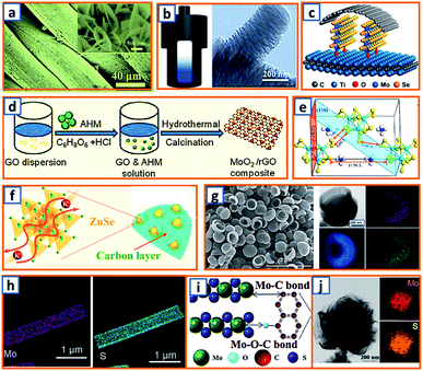 |
| | Fig. 3 Preparation of KIB anodes through hydrothermal treatment. (a) Morphology of SnO2 NSs grown on stainless steel mesh. Reproduced with permission.3 Copyright 2018, Elsevier. (b) Hydrothermal synthesis of oriented mesoporous graphitic carbon nanospring and its TEM image. Reproduced with permission.30 Copyright 2019, Wiley. (c) Schematic structure of hydrothermally synthesized MoSe2/MXene@C. Reproduced with permission.44 Copyright 2019, American Chemical Society. (d) Synthesis process of the MoO2/rGO composite as a PIB anode. Reproduced with permission.48 Copyright 2019, Wiley. (e) Geometric structure of (NH4)2Mo3S13; the yellow, cyan, blue, and white spheres represent S, Mo, N, and H atoms, respectively. Reproduced with permission.63 Copyright 2020, American Chemical Society. (f) Schematic illustration of the hydrothermally synthesized ZnSe CS/C. Reproduced with permission.82 Copyright 2020, The Royal Society of Chemistry. (g) Morphology and elemental mapping of the hydrothermal carbon hollow bowls. Reproduced with permission.112 Copyright 2019, American Chemical Society. (h) Elemental distribution of molybdenum and sulfur in synthesized MoS2 NWs. Reproduced with permission.120 Copyright 2019, The Royal Society of Chemistry. (i) Schematic structure of hydrothermal MoS2@rGO and (j) the flower-like MoS2 without graphene. Reproduced with permission.124 Copyright 2019, Elsevier. | |
2.2 Mechanical milling
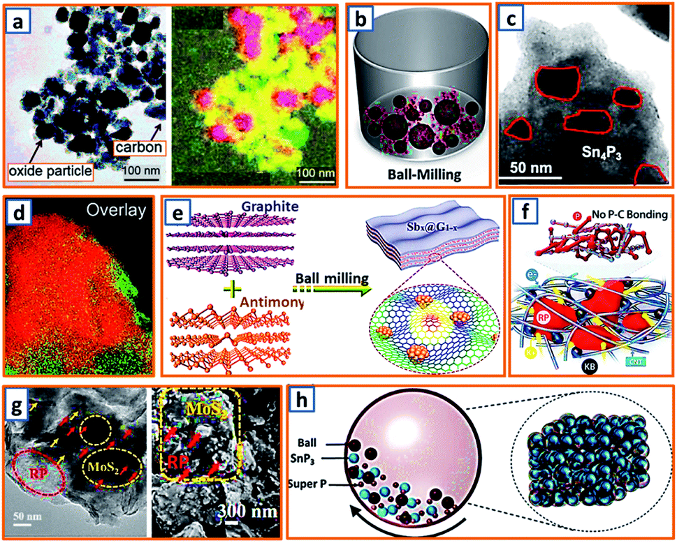
Milling is used to pulverize bulk materials into fine particles and to prepare secondary particles through repeated flattening, fracturing, and welding.147 Such a simple and cost-effective strategy is highly attractive as it has the potential to be scaled up for mass production.148 To improve the cycling stability and charge capacity, the hybridized Co3O4 and Fe2O3 were dispersed in a carbon matrix by Rahman et al. via a ball-milling process and applied for potassium storage.14 The hybrid was integrated into chain-like carbon black, and the overlay of elemental cobalt, iron, and carbon mapping highlighted the location and distribution of Co3O4, Fe2O3, and super P carbon in the sample (Fig. 4a). Super P, as the conductive scaffold between the current collector and metal oxide nanoparticles (NPs), confirmed reliable contact for fast electron transfer. To further enhance the potassium storage capability of graphite, Wu et al. fabricated a phosphorus/carbon composite via a simple milling process of commercial red phosphorus (RP) and graphite.34 As illustrated in Fig. 4b, a milling pot filled with 20 wt% RP and 80 wt% graphite was sealed in an argon atmosphere and rotated at 500 rpm for 48 h, forming island-like phosphorus uniformly spread in a sea-like highly conductive carbon matrix. The K-ion transport path and particle breakage owing to the volume expansion of phosphorus during potassiation could be shortened and alleviated, respectively.34 Additionally, a Sn4P3/C composite synthesized by means of conventional milling was also proposed.52 Agglomerated microparticles consist of numerous crystalline Sn4P3 NPs (ca. 20–50 nm) distributed evenly in the amorphous carbon (Fig. 4c). Because Sn4P3 is a relatively safe anode material, this work may be beneficial for the exploitation of safe, high-energy-density, and low-cost rechargeable KIBs. Alexey et al. prepared black phosphorus/graphite (BP–C) composites via planetary ball milling at 200 rpm; the obtained BP–C exhibited excellent mixing of phosphorus and carbon components (Fig. 4d).62 To maintain Sb stability, a series of Sb–graphite composites were also synthesized through facile milling of commercial Sb and graphite as anodes for potassium storage. Finally, the Sb nanoclusters were incorporated into graphite layers by the molecular diffusion effect during the ball milling and ultrasonic process, which was beneficial for the prevention of Sb aggregation, as illustrated in Fig. 4e.83 Considering that the effective utilization of RP as an active material in KIBs had not been well-studied, Tuan et al. attempted a one-pot milling approach to prepare activated RP/C-based KIB electrodes composed of RP, multi-wall carbon nanotubes (CNTs), and Ketjen black, wherein the RP NPs were evenly dispersed in a carbon matrix with desirable electrical pathways and strong scaffolds.95 Notably, there was no P–C bond formed in the composite, which might be beneficial for the effective reaction between K-ions and RP (Fig. 4f). RP was also incorporated with MoS2 to form a promising mosaic RP/MoS2 hybrid, as reported by Hou's group.106 After homogeneous mixing, commercial RP and bulk MoS2 powder were transferred and vigorously milled in a stainless steel jar. Taking advantage of the high-energy shear force, a large particle size was decreased and a mosaic hybrid was formed, presenting an RP-embedded architecture with a rough surface and abundant microchannels (Fig. 4g). This alleviated the volume expansion and agglomeration of RP particles. To conquer the intrinsic inaccessibility of bulk SnP3 in KIBs, Rakesh et al. proposed an effective milling process and elucidated, for the first time, the use of SnP3 active materials.116 Firstly, SnP3 was prepared via the reaction between metallic Sn and RP. Thereafter, 20 wt% super P was milled with the obtained SnP3 NPs for 3 h to ensure strong adhesion of amorphous carbon (Fig. 4h). This structure provided a facile approach to optimize electron transfer and enhance SnP3 utilization. Obviously, mechanical milling could provide a facile and reliable way to decrease the product size, enrich the surface active sites or trigger some solid-phase reactions. Nevertheless, its low efficiency and large energy consumption should also be taken into account. Besides, the negative effect of intensive vibration and harsh noise on scholar's daily research work should also be alleviated through protective measurements.
 |
| | Fig. 4 Synthesis of KIB anodes via mechanical ball milling method. (a) Bright-field image and an overlay of ball mill-synthesized Co3O4–Fe2O3/C anode (color scheme: cobalt-green; iron-red; carbon-yellow). Reproduced with permission.14 Copyright 2017, The Royal Society of Chemistry. (b) Schematic diagram of the ball milling of the P/C composite. Reproduced with permission.34 Copyright 2018, Elsevier. (c) TEM image of the milled Sn4P3/C NPs. Reproduced with permission.52 Copyright 2017, American Chemical Society. (d) Overlay of the maps of phosphorus (red) and carbon (green). Reproduced with permission.62 Copyright 2017, The Royal Society of Chemistry. (e) Schematic ball milling of the antimony-graphite composites. Reproduced with permission.83 Copyright 2019, Wiley. (f) Schematic illustration of structural configuration of activated RP/C-based PIB electrode. Reproduced with permission.95 Copyright 2019, Wiley. (g) TEM and SEM images of the ball-milled RP/MoS2 hybrid. Reproduced with permission.106 Copyright 2019, Wiley. (h) Ball milling process of SnP3/C nanocomposite. Reproduced with permission.116 Copyright 2019, American Chemical Society. | |
2.3 Chemical etching process
MXenes, which collectively represent transition metal carbides/carbonitrides/nitrides, have attracted considerable attention in the electrochemical energy field, including potassium storage batteries.149 The synthesis of MXenes is primarily carried out via the selective etching of the “A” element from the layered ternary MAX precursor using etchants, where M represents a transition metal, A is a group 13 or 14 element, and X is carbon and/or nitrogen. In addition, the etching process can also act as a buffer space in the designed porous or hollow products, which enhances the potassium storage capability. Fig. 5a demonstrates the fabrication of alkalized Ti3C2 (a-Ti3C2) MXene nanoribbons by the continuous etching of pristine Ti3C2 MXene in an aqueous KOH solution.9 Notably, Ti3C2 MXene NSs were first synthesized in sealed plastic containers with 60 mL aqueous HF solution (40%), which was followed by continuous shaking in a 6 M KOH aqueous solution for 72 h. Profiting from the expanded interlayer space, narrow nanoribbon-like structure, and 3D interconnected porosity, the obtained a-Ti3C2 anodes exhibited enhanced ion reaction kinetics and improved structural stability during potassium storage. Yang et al., for the first time, reported the electrochemical behavior of porous germanium anodes obtained by a facile chemical etching process.28 Two Al–Ge alloys (Al70Ge30 and Al80Ge20) were designed by refining Al and Ge in a vacuum arc furnace at an ultrahigh temperature. By tuning the Ge–Al composition and etching time, products with various porous structures were obtained (Fig. 5b). This presents a new approach toward the structural optimization of Ge electrodes. To further exploit the optimum anode materials, Bao et al. also reported the transformation of accordion-like Ti3C2 MXene to potassium titanate (M-KTO, K2Ti4O9) nanoribbons. After the solid–liquid reaction of ball-milled Ti, Al, and graphite powder at high temperatures, the obtained Ti3AlC2 was selectively etched and then alkalized, thereby forming M-KTO ribbons. As shown in Fig. 5c, the accordion-like multilayered Ti3C2 was successfully fabricated from densely packed Ti3AlC2. After treating Ti3C2 in an alkaline solution, there was an evident color change, which indicated the transformation into urchin-like M-NTO and M-KTO with a self-woven framework. The transformation approach is valuable for the further development of a variety of MXene-derived nanomaterials. Furthermore, SiOx is an effective sacrificial template for the synthesis of KIB anodes. Recently, bicontinuous and nanoporous carbon spheres (BC–NCS), consisting of a continuous nanocarbon framework and interconnected nanopores, were designed and prepared by Ji et al. by etching the SiOx template.68 Specifically, SiOC ceramic powders prepared via a two-step sol–gel process followed by pyrolysis were KOH-etched and calcinated at 800 °C before they were applied as a KIB anode. As shown in Fig. 5d, the obtained BC–NCS maintained interconnected nanopores and a continuous carbon framework, providing fast ion diffusion channels, sufficient volume expansion alleviation, and super electron-transport capabilities. A similar acid etching strategy was proposed by Alshareef's group for the synthesis of nitrogen-doped, defect-rich graphitic nanocarbons (GNCs).85 With the assistance of a NaCl template, an ethylenediamine tetra-acetate nickel coordination compound was carbonized under the catalysis of nickel and then etched in HCl solution before the collection of the GNC active material (Fig. 5e). A unique hollow bubble-like structure was observed owing to the delicate designation and facile acid etching. Similarly, a silicon carbide-derived carbon composite with a controllable pore structure was proposed using a concise etching approach.102 The unique pore structure maintained a high proportion of the mesopore volume (Fig. 5f), which confirmed the presence of sufficient active sites for enhanced potassium adsorption and accumulation. Apparently, chemical etching method is an effective way to create layered, porous and hollow structures. But some drawbacks still hinder its widely application in the preparation of KIB anode active materials. Generally, it is time-consuming to realize a sufficiently etched product, and the etching process always produces large amount of acid wastes, which is very hard to be dealt with and harmful to the environment. Additionally, the surface properties of obtained products could be significantly changed by the acid used during the etching process. Thus, much more effort are still needed to optimize this synthesis process.
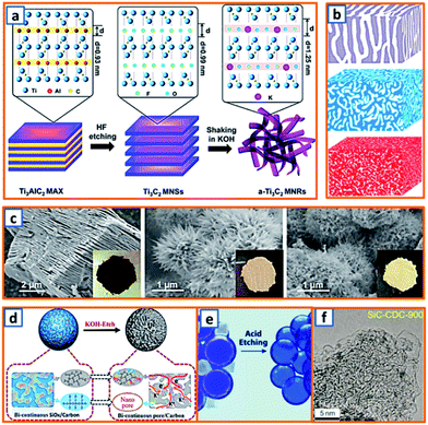 |
| | Fig. 5 Preparation of KIB anodes through chemical etching process. (a) Schematic of the synthesis of a-Ti3C2 MNRs via etching method. Reproduced with permission.9 Copyright 2017, Elsevier. (b) Schematic illustrations of three etched nanoporous samples: np-Ge30, np-Ge20 and np-AlGe. Reproduced with permission.28 Copyright 2019, Elsevier. (c) Morphology images of Ti3C2 MXene, M-NTO, and M-KTO. Reproduced with permission.11 Copyright 2017, American Chemical Society. (d) Schematic illustrations of the fabrication process of BC–NCS by etching SiOC ceramic spheres using molten KOH. Reproduced with permission.68 Copyright 2019, Elsevier. (e) Schematic illustration of the acid etching process of graphitic nanocarbons. Reproduced with permission.85 Copyright 2019, Wiley. (f) TEM image of the silicon carbide-derived carbon anode synthesized using a concise etching approach. Reproduced with permission.102 Copyright 2020, Wiley. | |
2.4 Other strategies
In addition to the abovementioned methods, several other effective strategies, such as facile annealing, co-precipitation, electrospinning, spray drying, electrodeposition, and chemical vapor deposition (CVD) have also been explored and applied in the preparation of KIB anodes.
2.4.1 Facile annealing.
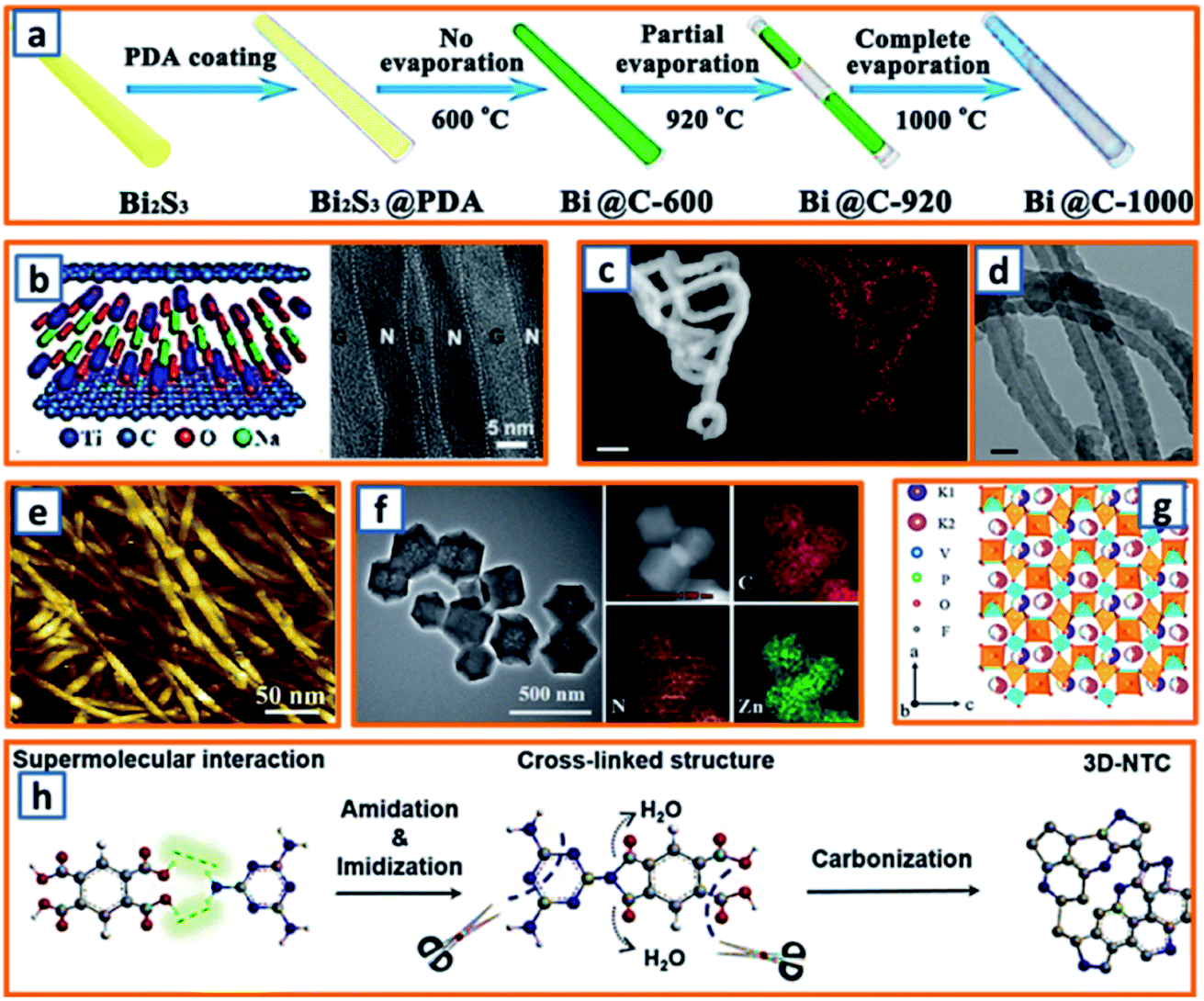
To strengthen the application of Bi metals based on their excellent conductivity and relatively low working potential, Qu et al. fabricated Bi nanorods encapsulated in N-doped CNTs (hollow Bi@C nanorods) through the facile annealing of PDA-coated Bi2S3 nanorods and partial evaporation of Bi at increased temperatures (Fig. 6a).10 The Bi contents of Bi@C-600, Bi@C-920, and Bi@C-1000 were estimated as 91.3, 81.2, and 0 wt%, respectively, which might be related to the low melting point of Bi and uniform shrinkage of pyrolyzed PDA during the facile annealing process. Through facile annealing, Qiao et al. confined MXene with rGO NSs and then transformed MXene into ultrathin titanates with a well-confined layered structure.31 The as-obtained sandwiched hybrid sample exhibited remarkable mechanical performance and maintained the merits of thin titanates and the impressive conductivity of rGO (Fig. 6b). To highlight the importance of N-doped soft carbon and its correlation to K storage performance, Xu et al. synthesized N-doped carbon nanofibers (NCNFs) with a high N-doping level of 13.8%.55 A polypyrrole (PPy) precursor was first prepared through the polymerization of the pyrrole monomer. After filtration, the black precipitate was annealed in an inert atmosphere for 2 h, leading to the formation of NCNFs. The incorporation of N and its even distribution over the entire nanofiber were observed (Fig. 6c), and the hollow interior of the nanofibers was also recorded (Fig. 6d). Guo et al. further fabricated NCNFs via the facile annealing of bio-waste chitin.65 Pure chitin, as the second most abundant biopolymer, possessed a smooth surface morphology with a fine nanofibrous structure with a uniform diameter of approximately 10–30 nm (Fig. 6e). It was heat-treated at various temperatures (500, 700, and 900 °C), and the product with the optimum composition was identified. Inspired by the ultrahigh physicochemical stability of the carbon matrix, Zhao and coworkers delicately dispersed zinc active particles in a nanoporous carbon network (ZNP/C), considering that zinc particles suffer from severe volume expansion during potassiation.84 During the fabrication process, the ZIF-8 precursor obtained by aging the mixture of 2-methylimidazole and Zn(NO3)2·6H2O in methanol was directly annealed at a specific temperature. Inherited from the polyhedral morphology of the ZIF-8 precursor, uniform polyhedral ZNP/C (ca. 250 nm) were identified, as shown in Fig. 6f. The uniform distribution of Zn, C, and N was also realized. Moreover, through facile annealing of a vacuum-dried mixture of NH4H2PO4, H4NO3V, KF, and citric acid, Zhang et al. collected a type of black powder, i.e., KVPO4F.96 In the refined KVPO4F structure, VO4F2 octahedral and PO4 tetrahedral building blocks were observed (Fig. 6g). Two half occupied K ion sites were identified, which indicated the possibility of accommodating one more K ion per KVPO4F. Encouraged by the efficient storage of potassium in active sites at edge-nitrogen-induced defects, Alshareef and coworkers reported a carbon anode with an ultrahigh edge-nitrogen level using pyromellitic acid (PMA) and melamine (MA) as monomers.111 A white PMA–MA supermolecule was first prepared by stirring PMA and MA in a sealed glass bottle. Thereafter, 3D N-doped turbostratic carbon was obtained through a one-step heat treatment (Fig. 6h). Owing to the high nitrogen level in MA and good thermal stability of the amide and imide structures, the optimized carbon anodes maintained an ultrahigh nitrogen doping level (22.8 at%) and ultrahigh edge-nitrogen doping level (16.8 at%), which is highly beneficial for potassium storage. Facile annealing is quite an easy way to realize the carbonization or crystallization of precursor materials for KIB anodes. Nevertheless, during the application of this synthesis approach, the structure or component of collected products are relatively hard to be adjusted.
 |
| | Fig. 6 Synthesis of KIB anodes through facile annealing. (a) Schematic illustration of synthesis process of Bi@C samples through facile annealing. Reproduced with permission.10 Copyright 2020, Elsevier. (b) Structure of NTO/rGO films and its cross-sectional TEM image. Reproduced with permission.31 Copyright 2018, Wiley. (c) Nitrogen mapping (orange) of facile annealed N-doped carbon nanofibers, and (d) TEM image of their hollow structure. Reproduced with permission.55 Copyright 2018, Nature. (e) AFM image of pure chitin before annealing process. Reproduced with permission.65 Copyright 2017, Elsevier. (f) TEM image of the annealed Zn NPs confined in carbon network and their elemental mapping. Reproduced with permission.84 Copyright 2018, The Royal Society of Chemistry. (g) Crystal structure of the facile annealed KVPO4F anode. Reproduced with permission.96 Copyright 2019, The Royal Society of Chemistry. (h) Schematic diagram of the annealing mechanism of the PMA–MA supermolecule. Reproduced with permission.111 Copyright 2020, Wiley. | |
2.4.2 Co-precipitation.
Capitalizing on the hydrogen bonding and electrostatic interactions between chitosan chains and GO sheets, Quan's group rationally fabricated a SnP0.94 nanoplate/GO (SnP0.94@GO) composite through a delicate precipitation process, during which the addition of chitosan triggered the autonomous encapsulation of GO sheets on the surface of the SnP0.94 nanoplates (Fig. 7a).4 Zhao et al. also reported a novel di-sodium organic salt as a KIB anode, which was synthesized by the facile precipitation of ortho-di-sodium salts of tetrahydroxyquinone (o-Na2C6H2O6).24 With the help of quickly injected sodium carbonate, dark purple o-Na2C6H2O6 crystals with irregular morphology were separated from the yellow solution of sodium carbonate and inositol (Fig. 7b). To provide sufficient space for the storage of large-sized K-ions, Alex and coworkers proposed an ultrathin, crisp-like bimetallic Fe–Mo selenide@N-doped carbon core/shell composite (FMSC).50 Firstly, a mixture of FeCl3, H2MoO4, oleylamine (OAm), and oleic acid was dehydrated and degasified at 90 °C. After the addition of Se and heat treatment at 180 °C, a dark precipitate of FeMoSe4@OAm nanoplates was obtained and further carbonized into FMSC. As shown in Fig. 7c, the curved crisp-like morphology with a diameter of 400–500 nm and an interlayer spacing of 0.74 nm facilitated the transfer of ions, confined the FeMoSe4, and maintained the integrity of the electrode. A precipitation strategy was also applied to alleviate the agglomeration and pulverization of Sb-based active materials. Lu's group delicately embedded Sb NPs (ca. 19 nm) into porous carbon networks (Sb-NPs@PC) through the co-precipitation of Sb-MOF and carbonization.70 Notably, the Sb-NPs@PC product had a uniform size and even Sb distribution (Fig. 7d), which could sufficiently buffer the mechanical stress of the potassiated Sb. Moreover, Deng et al. further enhanced the stability of Sb-based alloy anodes by designing 3D porous Sb–Co nanocomposites.89 A simple reduction precipitation was performed using SbCl3 and CoCl2 as precursors and NaBH4 as the reducing agent (Fig. 7e), resulting in highly porous Sb–Co NPs (Fig. 7f) compared to pure Sb particles. However, the further application of this strategy is significantly hindered by the undesirable instability of NaBH4. Notably, Lu et al. reported that surfactants could also be utilized to assist the precipitation process during the synthesis of oxygen-rich carbon microsphere anodes.100 With the self-assembly of low-cost urea and formaldehyde, the adoption of hard templates or dangerous hydrothermal devices (Fig. 7g) was avoided, and the nanoflake-interlaced microstructure of the obtained carbon microspheres verified the stability of anodes during the charge/discharge process (Fig. 7h). For co-precipitation technique, the morphology and structure of designed sample are easy to be adjusted by optimizing the solution concentration, stirring speed and type of precipitating agent. More effort is needed to promote the application of this technique in mass production, and the liquid-phase reactions in the large-volume retort significantly different from those in laboratory beaker should be carefully investigated.
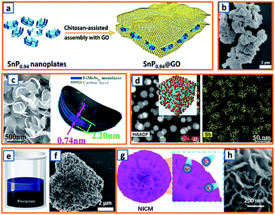 |
| | Fig. 7 Co-precipitation process for the preparation of KIB anodes. (a) Schematic depicting the precipitation of the SnP0.94@GO composite. Reproduced with permission.4 Copyright 2019, Elsevier. (b) SEM image of precipitated Na2C6H2O6. Reproduced with permission.24 Copyright 2018, Elsevier. (c) Morphology and schematic diagram of the Fe–Mo selenide@N-doped carbon anode. Reproduced with permission.50 Copyright 2018, Elsevier. (d) Morphology and Sb distribution in the Sb-NP@PC anode. Reproduced with permission.70 Copyright 2019, The Royal Society of Chemistry. (e) Schematic illustration and (f) SEM image of Sb–Co precipitate. Reproduced with permission.89 Copyright 2019, Elsevier. (g) Schematic illustration and (h) microstructure of the nanoflake-interlaced carbon microspheres. Reproduced with permission.100 Copyright 2020, The Royal Society of Chemistry. | |
2.4.3 Electrospinning.
As 1D carbon materials (e.g., nanotubes, nanowires, nanorods, and nanofibers) are favorable for the mitigation of volume change during K–Sb alloying, Hu et al. proposed the fabrication of Sb@CN nanofibers with nano-Sb confined in N-modified carbon fibers via an electrospinning process (Fig. 8a).2 The nano-Sb was independently embedded in the CNFs, presenting a rod-like shape with a diameter ranging from 10 to 30 nm and boosting reaction kinetics during cycling. Electrospinning was also applied in the synthesis of coal liquefaction residue-based nanofibers with polyacrylonitrile (PAN) and preasphaltene (PA) selected as the precursor.27 Compared to pure PAN-based electrospun fibers, the PAN–PA fiber had a yellowish-brown color, indicating a good incorporation of PA in PAN during the electrospinning process (Fig. 8b). After peroxidation and calcination, the as-spun PA-PAN carbon fiber was collected; it comprised a short and disordered turbostratic structure with a higher interlayer distance (0.375 nm), which favored the rapid insertion of K ions. To promote the potassium storage performance of the electrospun fibers, Yang et al. decorated N-doped carbon microfibers with CuO/Cu clusters, providing a 3D microfiber network (CuO/Cu-NCNFs) with an average diameter of 300 nm (Fig. 8c).46 Thus, electrospinning is a good way to produce uniform fibres with large specific area, low aggregation and reliable mechanical strength. When applied as the KIB anode, it exhibits desirable ion kinetic behavior and high energy storage efficiency. However, the electrospinning process is intensively influenced by many parameters, such as voltage, spinning rate, flying distance between the needle and collector, rotating speed of the collector, concentration and viscosity of the polymer solution, ambient temperature and humidity, and type of solvent. Thus, sufficient preparations are quite essential before fibre preparation through electrospinning.
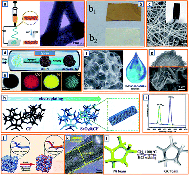 |
| | Fig. 8 Electrospinning, spray drying, electrodeposition, and CVD. (a) Electrospinning process and the corresponding microstructure of Sb@CN nanofibers. Reproduced with permission.2 Copyright 2020, Elsevier. (b) As-spun preasphaltene/PAN (b1) and PAN (b2) fibers. Reproduced with permission.27 Copyright 2020, American Chemical Society. (c) SEM images of CuO/Cu-NCNFs. Reproduced with permission.46 Copyright 2020, Elsevier. (d) Schematic illustration of the spraying process and (e) corresponding elemental mapping of the CoTe2–C composite. Reproduced with permission.64 Copyright 2020, Elsevier. (f) SEM of the obtained N-doped interconnected carbon spheres and the NaCl/C6H17N3O7 precursor for spraying. Reproduced with permission.81 Copyright 2019, The Royal Society of Chemistry. (g) Morphology of the activated crumpled graphene after the spray drying process. Reproduced with permission.99 Copyright 2020, Wiley. (h) Schematic of the electrodeposition process of SnO2@CF and (i) XRD spectrum after deposition. Reproduced with permission.16 Copyright 2020, The Royal Society of Chemistry. (j) CVD for the fabrication of red P@AC. Reproduced with permission.119 Copyright 2020, Elsevier. (k) Microstructure of multiwalled hierarchical carbon nanotube after CVD. Reproduced with permission.125 Copyright 2018, Wiley. (l) CVD for the synthesis of graphitic carbon foam. Reproduced with permission.129 Copyright 2019, The Royal Society of Chemistry. | |
2.4.4 Spray drying method.
The spraying method is another effective method for structural engineering and morphological control of KIB anodes. Kang et al. reported CoTe2–C composite microspheres via a spraying process.64 Briefly, TeO2 in nitric acid was added to the solution of cobalt nitrate and sucrose, forming a homogeneous mixture for further spraying at a flow rate of 5 L min−1 (Fig. 8d). This process ensured the uniform distribution of the ultrafine CoTe2 nanocrystals in the CoTe2–C composite microspheres, as indicated in Fig. 8e. This was beneficial for improving the cycling stability and rate performance during the potassium storage process. The template-assisted spray method was then proposed by Li et al., which used low-cost NaCl as a template and C6H5O7(NH4)3 as the carbon precursor.81 After calcination and water washing, 3D N-doped carbon nanosheets (UNCns) with a spherical network-like structure consisting of continuously interconnected carbon nanoboxes were obtained (Fig. 8f). The wrinkled and ultrathin features of the CNSs endowed UNCns with abundant active sites for energy storage. The GO slurry, as a highly malleable material, was also employed as the precursor material for the spraying synthesis of the defective activated-crumbled graphene (A-CG) anode.99 During the fast spray drying process, a ruffled ball-like morphology with a ridge structure was formed by partial stacking and folding of the NSs (Fig. 8g). Typically, the product of the spray drying process has a relatively uniform size and controlled microstructure, which are both beneficial for the industrial application of KIB anodes. This indicates the promising potential of the spray drying technique in the preparation of KIB active materials. Although spray drying has attracted enormous attention because of its unique features (e.g., mature technology, easy operation and continuous production), it is noteworthy that only limited solutions, emulsions, suspensions or molten liquids are suitable for spray drying. And the physical and chemical properties of precursors, especially the possible hazards under high temperature should be carefully taken into consideration.
2.4.5 Electrodeposition method.
Electrodeposition was adopted by Hou et al. to anchor SnO2 NPs on 3D carbon foam (SnO2@CF) as a freestanding KIB anode.16 As shown in Fig. 8h, a carbon fiber and carbon rod were used as the working and counter electrodes, respectively, while electrodeposition was conducted in a stationary electrolyte solution containing SnSO4 and H2SO4 through the reactions: SO42− + H2O + 2e− → SO32− + 2OH− and Sn4+ + 4OH− → SnO2 + 2H2O. The X-ray diffraction (XRD) spectrum of the as-deposited product (Fig. 8i) indicated that SnO2 with (110), (101), and (211) planes was successfully anchored on the carbon foam matrix. Therefore, electrodeposition is a good way to deposit specific active materials on selected scaffold. But, the voltage and current should be carefully controlled to avoid the formation of uneven nanoparticles, which could deteriorate the performance of electrodeposited electrode.
2.4.6 Chemical vapor deposition.
CVD is another widely used strategy for the preparation of reliable KIB anodes. In the CVD process, active material in the gas phase such as phosphorus, CH4 and C2H6 could easily deposit or be pyrolyzed on the surface and the pores of targeted matrix, forming an ideal combination of active material and conductive matrix. For example, Qu et al. confined nanoscale RP within a porous carbon structure through a delicately controlled RP vapor deposition process.119 A dual protection of RP was further obtained by the surface coating of PPy on RP-embedded carbon (P@AC) (Fig. 8j). In the obtained product, the structural stability and oxidation resistance of the assembled electrode were effectively enhanced by the successful encapsulation of the active material. A multiwalled hierarchical carbon nanotube (HCNT) was obtained by Han and coworkers through CVD treatment on skeletal CNT.125 Ferrocene and 1,2-dichlorobenzene were applied as the catalyst and carbon precursor, respectively, in a CVD furnace with a mixture of Ar and H2 as the carrier gas. The unique HCNTs consisted of densely stacked graphitic inner CNTs and loosely stacked outer CNTs (Fig. 8k), and were further interconnected to a hyperporous bulk sponge, which maintained the developed porosity and tunable modulus. Taking advantage of the transition metal catalyst and reliable CH4 deposition chemistry, Yu's group also designed a kind of CNT-modified graphitic carbon foam (CNTs/GCF) as KIB anodes.129 The graphitic carbon foam was first obtained on the surface of Ni foam in a CH4 atmosphere (Fig. 8l), and then anchored by NiCo catalysts to form NiCo–O/GC. After repeated CVD treatment using C2H4 as the carbon source, abundant CNTs adhering to the surface of the 3D GCF were obtained. This rationally designed 3D structure exhibited a shortened ion diffusion path and promoted ion migration. The gas phase of the chemical precursor in the CVD process guarantees uniform dispersion or deposition of active materials. Although the CVD induced product maintains enhanced K+ kinetics, buffered volume change and improved cycling stability, the high cost and strict requirement of CVD equipment still significantly hinder its large-scale application. Notably, the combustible gas detection devices are indispensable during the anode preparation to avoid possible explosion. Besides, typical synthesis processes of KIB anodes are organized in Table 1.
Table 1 Synthesis processes of typical KIB anodes
| Typical KIB anodes |
Synthesis strategies |
Main precursors |
Synthesis conditions |
Ref. |
| SnO2 nanosheets |
Hydrothermal treatment |
NaOH; SnCl2; water |
200 °C for 24 h |
3
|
| Graphitic carbon nanospring |
Hydrothermal treatment |
Epoxy resin; water |
500 °C for 10 h |
30
|
| MoO2 hollow sphere |
Hydrothermal treatment |
Ammonium heptamolybdate; ascorbic acid; GO dispersion |
180 °C for 15 h |
48
|
| Sulfur-rich (NH4)2Mo3S13 |
Hydrothermal treatment |
Sodium molybdate; thioacetamide; water |
160 °C for 24 h |
63
|
| ZnSe/C nanocage |
Hydrothermal treatment |
Zinc nitrate hexahydrate; 2-methylimidazole; methanol |
140 °C for 1 h |
82
|
| Phosphorus/carbon composite |
Mechanical milling |
Red phosphorus; graphite powder |
500 rpm for 48 h |
34
|
| Sb–graphite composites |
Mechanical milling |
Graphite; Sb power |
450 rpm for 24 h |
83
|
| Activated red P/carbon |
Mechanical milling |
Red phosphorus; multi-wall carbon nanotubes; Ketjen black |
300 rpm for 12 h |
95
|
| Mosaic RP/MoS2 hybrid |
Mechanical milling |
Commercial red phosphorus, bulk MoS2 powder |
500 rpm for 24 h |
106
|
| Ti3C2 MXene nanoribbons |
Chemical etching process |
Ti3AlC2 powder; HF solution (40%); 6 M KOH |
HF etching for 72 h; KOH etching for 72 h |
9
|
| Bicontinuous and nanoporous carbon spheres |
Chemical etching process |
SiOC ceramic spheres; molten KOH |
High temperature (800 °C) etching for 2 h |
68
|
| Defect-rich graphitic nanocarbons |
Chemical etching process |
EDTA nickel coordination compound; sodium chloride; nickel chloride; HCl solution |
120 °C for 24 h; cold water reflux |
85
|
| Silicon carbide-derived carbon |
Chemical etching process |
Cubic silicon carbide; chlorine gas |
Chlorine etching; 900 °C for 2 h |
102
|
| Nitrogen-doped carbon nanofibers |
Facile annealing |
Polypyrrole fibre |
650 °C for 2 h; N2 atmosphere |
55
|
| Zn nanoparticles confined in carbon network |
Facile annealing |
Zeolitic imidazolate framework-8 |
600 °C for 3 h; N2 flow |
84
|
| Chitin based carbon fibre |
Facile annealing |
Bio-waste chitin |
700 °C for 2 h; Ar atmosphere |
65
|
| SnP0.94 nanoplate/GO |
Co-precipitation |
SnP0.94 powder; GO suspension; chitosan solution |
Dropwise mixing; continuous stirring |
4
|
| FeMoSe4@N-doped carbon |
Co-precipitation |
Ferric chloride; molybdic acid; oleylamine; oleic acid; Se powder |
180 °C; existence of generated H2Se |
50
|
| 3D porous Sb-Co nanocomposites |
Co-precipitation |
Antimony trichloride; cobalt chloride; sodium citrate |
pH = 12; dropwise adding; continuous stirring |
89
|
| Nano Sb confined in N-doped carbon fibers |
Electrospinning |
Antimony trichloride; polyacrylonitrile |
Flow rate 10 μL min−1; voltage 10 kV |
2
|
| CuO/Cu–nitrogen-doped carbon microfibers |
Electrospinning |
Polyacrylonitrile; N,N-dimethylformamide; copper acetate monohydrate |
Flow rate 0.3 mm min−1; voltage 16 kV |
46
|
| CoTe2–C composite microspheres |
Spray drying |
TeO2; cobalt nitrate; sucrose |
550 °C; H2/Ar carrier gas; flow rate 5 L min−1 |
64
|
| 3D ultrathin nitrogen doped carbon nanosheets |
Spray drying |
Sodium chloride; ammonium citrate tribasic |
Air atmosphere; 150 °C |
81
|
| Activated crumpled graphene |
Spray drying |
Graphene oxide; deionized water |
100 °C; Ar carrier gas; flow rate 10 L min−1 |
99
|
| SnO2 nanoparticles on 3D carbon foam |
Electrodeposition |
0.04 M SnSO4; 0.5 M H2SO4 |
Current density 0.8 mA cm−1; deposition time 5 h |
16
|
| Red P@activated carbon composite |
Chemical vapor deposition |
Red phosphorus; activated carbon |
550 °C for 3 h; 260 °C for 24 h |
119
|
| Multiwalled hierarchical carbon nanotube |
Chemical vapor deposition |
Ferrocene; 1,2-dichlorobenzene |
880 °C; Ar (2000 mL min−1); H2 (300 mL min−1) |
125
|
| CNT-modified graphitic carbon foam |
Chemical vapor deposition |
Nickel foam; nickel nitrate; cobalt nitrate |
C2H4/H2/Ar (50/50/200 mL min−1); 750 °C |
129
|
3. Potassium storage chemistry
3.1 Alloying-type anode
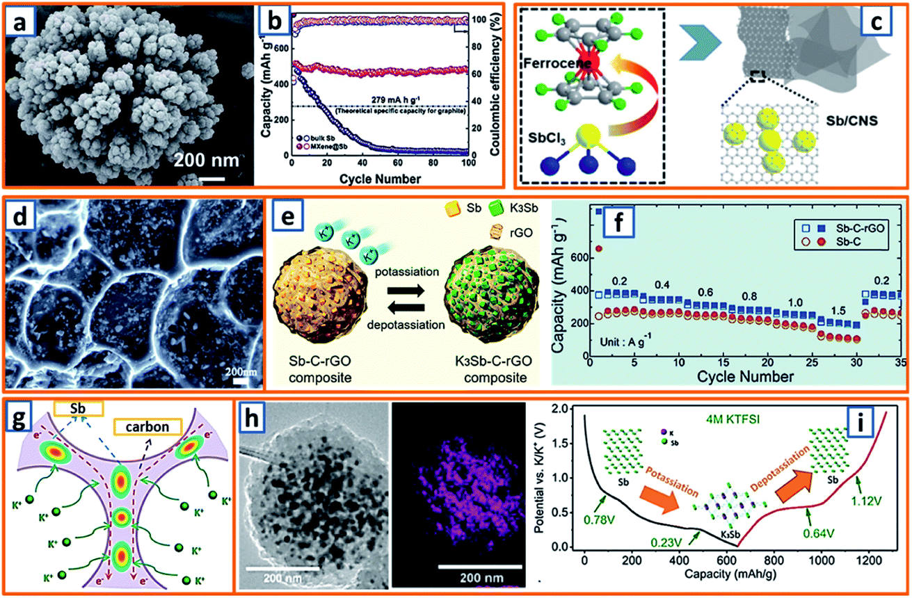
For the alloying-type anode, the electrochemical alloying process is typically exhibited as M + xK+ + xe− → MKx, where M is an alloying element and x is the stoichiometric coefficient for the chemical formula. Generally, a single atom can react with several K atoms, thereby leading to a substantially high specific capacity.150,151 Among the alloying elements, Sb has attracted considerable attention because of its low working potential and high theoretical capacity (660 mA h g−1) induced by the formation of K3Sb. Qian et al. successfully constructed a hierarchically porous alloying-type Sb on MXene paper.7 The Sb active material has a microscale flower-like Sb particle consisting of a large number of nanoscale particles and several voids/vacancies among various NPs (Fig. 9a). Owing to the synergistic effect between the hierarchical porosity of Sb and the high conductivity of MXene, the proposed MXene@Sb significantly enhanced the K storage capability. Specifically, compared to the rapid decay and poor cycling stability of bulk Sb, optimized MXene@Sb anodes maintained an ultrahigh capacity retention of 94.32% over 100 cycles (Fig. 9b). Antimony nanocrystal-embedded ultrathin carbon nanosheet (Sb/CNS) composites were also prepared by Han et al. during which SbCl3 was mixed with ferrocene before being sealed together with hexane in an autoclave (Fig. 9c).32 After heat-treatment at 330 °C for 10 h, Sb/CNSs were collected, and Sb nanocrystals (approximately 14.0 nm) were uniformly embedded in amorphous CNSs with a layer thickness of approximately 18.6 nm. However, without hexane addition, only a bulk Sb/C composite was achieved, which exhibited a much lower performance (100 mA h g−1 after 100 cycles) than that of Sb/CNS (247 mA h g−1 over 600 cycles). This emphasizes the importance of morphological control for the electrochemical performance of Sb-based KIB anodes. Similarly, Ju et al. reported a Sb@PC composite, wherein Sb NPs were homogenously embedded into a 3D porous carbon (Fig. 9d).47 A mixture of SbCl3, ethanol, and sodium polyacrylate was prepared under continuous stirring and then dried and carbonized at 600 °C in an Ar atmosphere. After thorough washing, the NaCl was removed, leaving the final Sb@PC. Owing to the unique structure, the intense volume expansion of the inner Sb alloying was inhibited, providing good K storage capability (250 mA h g−1 at 100 mA g−1). Graphene was further applied in the enhancement of alloy-type Sb by Kim et al., during which the prepared droplet containing Sb-tartrate and GO was dried and pyrolyzed into Sb–C–rGO spheres.69 During the K storage process (Fig. 9e), the graphene-enhanced Sb–C composite maintained an optimized rate performance, providing reversible capacities of 388–195 mA h g−1 at current densities ranging from 0.2–1.5 A g−1 (Fig. 9f). Furthermore, Han and coworkers designed a 3D carbon network that could confine Sb NPs effectively.78 After stirring a transparent solution of the polyvinylpyrrolidone, SbCl3, and NaCl template for 30 min, the mixture was freeze-dried and heat-treated, thereby realizing the formation of 3D SbNPs@C composites (Fig. 9g), which combined the merits of the 3D structure and the high capacity of the Sb anode and provided a high reversible capacity of 225 mA h g−1 at 1000 mA g−1 over 50 cycles. To further enhance the integrity of the Sb-based KIB anode, Wang and coworkers also proposed an extremely stable Sb–C composite, wherein PAN was applied as the carbon matrix with uniformly embedded Sb NPs with an average size of 14 nm (Fig. 9h).101 In the charge–discharge behavior of Sb@CSN (Fig. 9i), two prominent discharge voltage plateaus at 0.78 V and 0.23 V were observed, which were related to the potassiation reaction of Sb to KSb2/KSb and K5Sb4/K3Sb, respectively, while the two charge platforms at 0.64 V and 1.12 V were attributed to the extraction of K from K3Sb to Sb.101 This work proposed an effective way to buffer the volume change of Sb and simultaneously investigated the K alloying process.
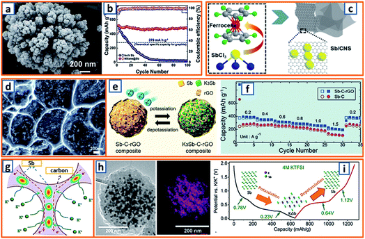 |
| | Fig. 9 Potassium storage chemistry and applications of Sb-based alloying-type anodes. (a) High-magnification SEM image of MXene@Sb anode, and (b) cycling performances of MXene@Sb and bulk Sb. Reproduced with permission.7 Copyright 2019, The Royal Society of Chemistry. (c) Schematic illustration of the solvothermal reaction and structural morphology of the Sb/CNS composite. Reproduced with permission.32 Copyright 2018, Elsevier. (d) Morphology of the Sb@PC anode. Reproduced with permission.47 Copyright 2018, Elsevier. (e) Electrochemical behavior of the Sb–C–rGO anode, and (f) its rate performance. Reproduced with permission.69 Copyright 2019, American Chemical Society. (g) Schematic illustration of the potassium storage behavior of 3D SbNPs@C. Reproduced with permission.78 Copyright 2018, The Royal Society of Chemistry. (h) TEM image and Sb mapping of an individual Sb@CSN sphere, and (i) typical second charge/discharge profile at 50 mA g−1. Reproduced with permission.101 Copyright 2019, The Royal Society of Chemistry. | |
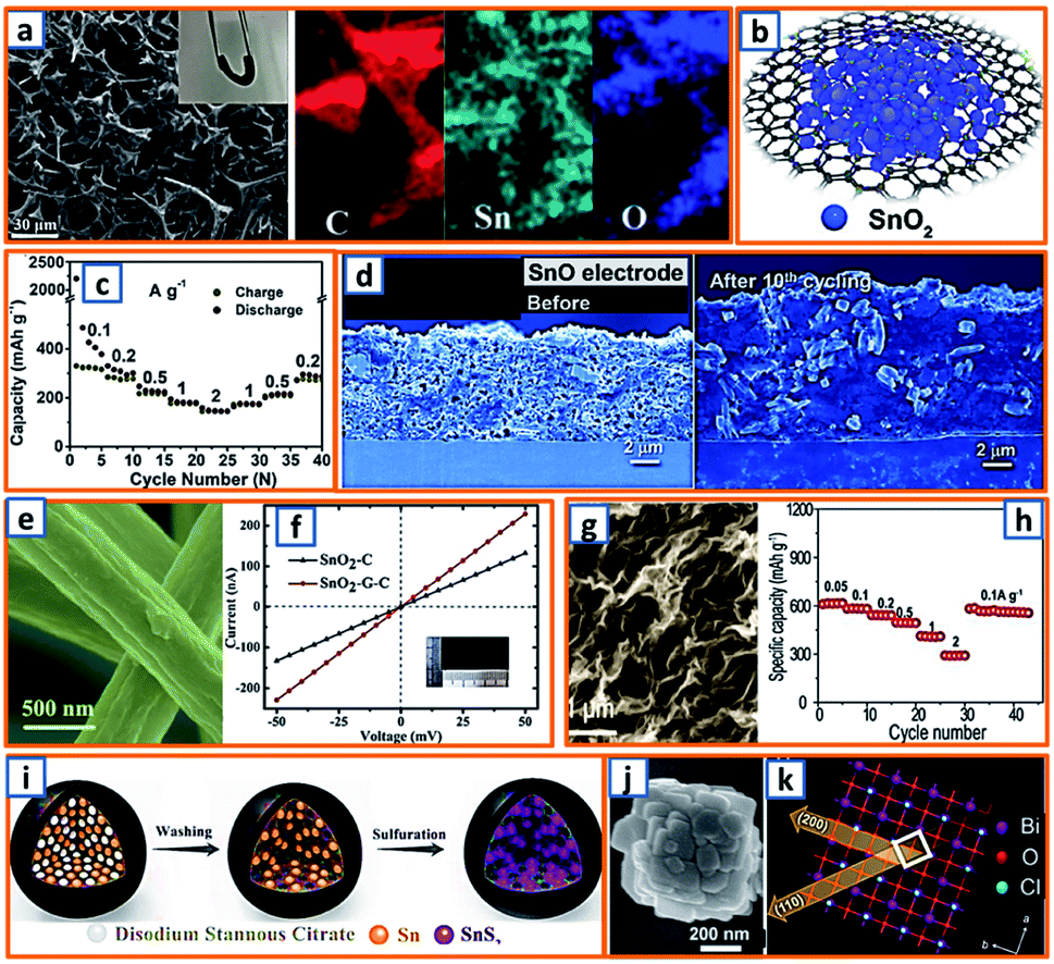
Tin could also form a reversible alloy with potassium and exhibit desirable specific capacity. Huang et al. reported 3D hierarchically porous carbon/Sn composites (HPCS) for KIB anodes using in situ generated NaCl crystals as templates.13 Specifically, stannic chloride pentahydrate, as the Sn source, and PANNa, as the carbon and template source, were mixed together, forming a white solution, which was subjected to freeze-drying and heat treatment. After facile template removal, 3D-HPCS were collected and evaluated at 50 mA g−1, revealing a high reversible capacity of 276.4 mA h g−1 after 100 cycles (Fig. 10a). The good performance was attributed to the unique microstructure with uniformly anchored Sn NPs on the ultrathin carbon wall-constructed network. To further pursue practical KIB with high energy density and long cycle life, Zhuang et al. proposed Sn-based submicron particles encapsulated in a porous rGO network as a KIB anode.36 Owing to the electronegativity of functional groups such as hydroxyl and carboxyl, a highly uniform distribution of Sn NPs between the graphene layers was obtained (Fig. 10b), leading to a high K storage capacity (200 mA h g−1) after 50 cycles and an excellent rate capability (67.1 mA h g−1 at 2000 mA g−1) (Fig. 10c). Notably, Sn@RGO with an enlarged interlayer space and wrinkled morphology was favorable for buffer volume change and ensured electrode integrity. As the KIB performance of pure Sn is relatively unsatisfactory due to inevitable mechanical degradation, Glushenkov's group designed a Sn–C composite by incorporating 30 wt% graphite with 70 wt% Sn.53 This ensured the stability and integrity of Sn-based anodes with active materials deeply embedded in a C-based matrix, as shown in the overlay of the energy-filtered elemental maps of C (yellow) and Sn (blue) (Fig. 10d).
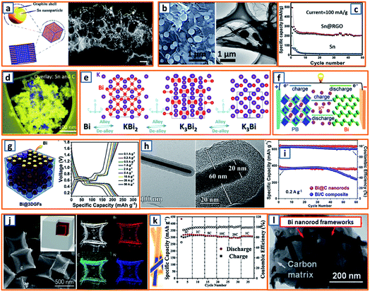 |
| | Fig. 10 Potassium storage chemistry and applications of Sn-, Bi-based alloying-type anodes. (a) Schematic synthesis and TEM image of the 3D-HPCS anode. Reproduced with permission.13 Copyright 2018, The Royal Society of Chemistry. (b) Microstructure and (c) potassium storage performance of the Sn@RGO composite. Reproduced with permission.36 Copyright 2019, Elsevier. (d) Distribution of Sn in the obtained Sn–C composite. Reproduced with permission.53 Copyright 2016, The Royal Society of Chemistry. (e) Alloying and dealloying processes in Bi electrode. Reproduced with permission.66 Copyright 2018, Wiley. (f) Application of the Bi-based anode in a KIB full cell. Reproduced with permission.26 Copyright 2018, Wiley. (g) Schematic illustration and galvanostatic charge–discharge profiles of the Bi@3DGFs anode. Reproduced with permission.97 Copyright 2019, The Royal Society of Chemistry. (h) TEM and (i) cycling performance of the Bi@C electrode. Reproduced with permission.110 Copyright 2019, Wiley. (j) SEM image and elemental mapping of carbon-coated double-shell bismuth hollow boxes. Reproduced with permission.117 Copyright 2019, Elsevier. (k) Schematic illustration of Bi@N-CT and its corresponding electrochemical performance. Reproduced with permission.122 Copyright 2020, The Royal Society of Chemistry. (l) TEM image of a Bi-based composite structure comprising Bi nanorod networks confined in a N, S co-doped carbon matrix. Reproduced with permission.130 Copyright 2020, The Royal Society of Chemistry. | |
Zhang and coworkers investigated the potassium storage behavior and identified continuous surface potassiation with K3Bi formed in the first discharge and reversible stepwise K3Bi–K3Bi2–KBi2–Bi dealloying–alloying behavior in subsequent cycles (Fig. 10e).66 To realize the fast kinetics and tolerance of its volume change, 3D Bi porous networks were developed by Lei's group.26 When a full KIB was fabricated in the configuration of Bi//dimethoxyethane (DME)-based electrolyte//hexacyanometallate (K0.72Fe[Fe(CN)6]) (Fig. 10f), a high discharge capacity (54.5 mA h g−1) and impressive cycling retention (86.5%) after 350 cycles, corresponding to a capacity decay of 0.039% per cycle, was observed. To address the pulverization of Bi-based active materials, Yu et al. reported a robust hierarchical structure with Bi NPs dispersed in 3D macroporous graphene framework (Bi@3DGF) via facile the heat treatment of filtered 3D graphene and triphenylbismuth.97 The conductive 3DGFs successfully introduced a defined buffer space for expanded Bi without destroying the electrode integrity and structural continuity, leading to slight polarization and low over-potentials during the charge/discharge process with voltage platforms evidently distinguished (Fig. 10g). Besides, a novel Bi nanorod was prepared by Ma et al. and fabricated as the core with amorphous carbon as the shell (Bi@C).110 Notably, the diameter of the Bi core and the thickness of the carbon shell were both approximately 20 nm (Fig. 10h), which demonstrated a desirable storage capacity of more than 360 mA h g−1 at 0.2 A g−1, which surpassed that of the Bi/C composite (Fig. 10i). The enhanced electrochemical performance could be ascribed to the facilitated ion diffusion by appropriate pore size and soothed mechanical stress by carbon coating in a rationally designed core–shell structure.110 It was noteworthy that double-shell-structured Bi boxes were another promising candidate as KIB anode materials because of their sufficiently soothed stress during the K storage process. Qiao et al. delicately designed an optimized carbon-coated double-shell Bi hollow box, denoted as C@DSBC, through the modified sulfidation of ZIF-8 cubes (ca. 500 nm) followed by carbon coating and calcination (Fig. 10j).117 With uniform N-doped carbon coating, the C@DSBC-based anode showed a reliable reversible capacity (300 mA h g−1), which was apparently higher than that of the unmodified Bi anode (65 mA h g−1). Moreover, Bi nanorods encapsulated in hollow N-doped CNTs were also explored, and they exhibited an impressive capacity retention (88%) after 1000 cycles, as well as excellent rate capability (297 mA h g−1 at 20C, 94% of the capacity at 1C) (Fig. 10k).122 The conductivity and structural integrity of Bi nanorods could also be effectively mitigated in the robust N, S co-doped carbon matrix (Bi/NS–C), as reported by Jiao and his coworkers.130 As expected, after 1000 cycles, an outstanding cycling stability (91% capacity retention at 5 A g−1) was achieved. In addition, high rate capabilities could also be obtained, illustrating reversible capacities of 338 mA h g−1 and 289 mA h g−1 at 0.5 and 6 A g−1, respectively.130 The rationally fabricated Bi–C composite significantly integrated the advantages of the N, S co-modified carbon framework, which functioned as a conductive network and tough mitigation of severe volume change, and a unique Bi rod-like structure with enhanced reaction kinetics, which accommodated large strains (Fig. 10l).
Phosphorus has been regarded as a promising alloying-type anode owing to its resource abundance, good diffusion kinetics, and desirable potassium storage ability with an impressive theoretical capacity of 843 mA h g−1 through the formation of KP.62 A hollow carbon with an ultrathin shell was prepared by Chen et al. to accommodate phosphorus active materials (75 wt% loading), resulting in the formation of a P@HC yolk/shell composite.141 Calcium carbonates were selected as the template for the synthesis of hollow carbon. After the facile template removal using HCl, hollow carbon could be collected with a wall thickness of approximately 5 nm, which was then mixed and heat-treated with phosphorus powder to form a perfect yolk–shell structure (Fig. 11a). When applied in KIBs, P@HC electrodes could provide a high reversible capacity of 841 mA h g−1, with an excellent rate capability (249 mA h g−1 at 5 A g−1, 29% of the capacity at 0.05 A g−1) (Fig. 11b). To promote the potassiation of phosphorus, Xu et al. successfully incorporated RP in interconnected CNSs through delicate vaporization and condensation (Fig. 11c), thereby realizing a superior electrochemical performance with a high reversible capacity of 655 mA h g−1 at 100 mA g−1.145 To investigate the potassium storage behavior of RP, density-functional theory (DFT) calculations were conducted, as depicted in Fig. 11d, revealing that the KP phase with the lowest formation energy (−0.421 eV) was the most thermodynamically stable form. Notably, Yu et al. proposed a rationally designed strategy to boost the KIB property by encapsulating phosphorus in N-modified hollow CNFs through KOH activation and phosphorus condensation.146 Compared with products without KOH activation, the as-optimized sample with a large surface area and high pore volume could effectively accommodate the large volume expansion and possess superior phosphorus stability (Fig. 11e), resulting in a significant enhancement in the potassium storage capability. Aiming to address the intrinsic insulating property and severe volume change of phosphorus-based active materials, Qu and coworkers successfully confined phosphorus in CNT-backboned mesoporous carbon (TBMC).152 To prepare TBMC, tetraethyl orthosilicate was first coated on commercial CNTs before they were wrapped with resorcinol-formaldehyde. After intensive etching of SiO2, purified phosphorus was condensed in the collected TBMC in a sealed tube at 600 °C, forming P/TBMC (Fig. 11f). When charged/discharged at 0.5 A g−1, it delivered a depotassiation capacity of 244 mA h g−1, even after 200 cycles in the KIB (Fig. 11g), implying the beneficial effect of microstructural optimization of the carbon host on the enhancement of the P–C anode. Black phosphorus could also be utilized as the main active component in KIBs, based on the research of Glushenkov and coworkers.62 Typically, black phosphorus obtained from the intensive milling of RP for 25 h in Ar could be incorporated with graphite under the same conditions. As shown in Fig. 11h, a reasonable rate capability with an original capacity above 400 mA h g−1 and a final capacity of 120 mA h g−1 at 500 mA g−1 was attained. Thus, through the formation of the KP alloy, phosphorus-based anodes could deliver a remarkably high reversible capacity, while a trade-off between the capacity and the content of phosphorus should be carefully made in the composites because of the severe volumetric change during charging and discharging. The detailed comparison of typical alloying-type anodes in potassium ion batteries is provided in Table 2.
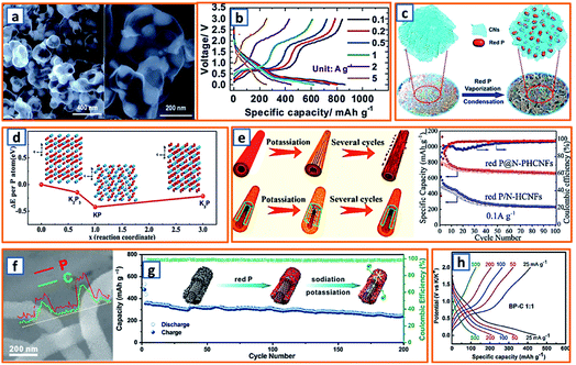 |
| | Fig. 11 Potassium storage chemistry and applications of phosphorus-based alloying-type anodes. (a) TEM image of P@HC (75 wt% P content) and (b) its charge/discharge curves at various current densities. Reproduced with permission.141 Copyright 2020, The Royal Society of Chemistry. (c) Schematic illustration of the synthesis process for RP@CN composite, and (d) its calculated formation energy. Reproduced with permission.145 Copyright 2018, Wiley. (e) Schematic illustration of the potassiation/depotassiation process of hollow carbon fibers coated with RP, and nanostructured RP confined in the N-PHCNF matrix, and their potassium storage performance. Reproduced with permission.146 Copyright 2019, American Chemical Society. (f) SEM and line scanning of P@TBMC and (g) its electrochemical performance. Reproduced with permission.152 Copyright 2018, Elsevier. (h) Rate capability for the black phosphorus/carbon electrodes. Reproduced with permission.62 Copyright 2017, The Royal Society of Chemistry. | |
Table 2 Summary of various alloying-type anodes in potassium ion batteries
| Electrode materials |
ICE |
Capacity |
Current density |
Cut voltage |
Retention |
Ref. |
| MXene@Sb |
∼45% |
475.1 mA h cm−3 |
50 mA g−1 |
0.01–1.2 V |
79%/500 cycles |
7
|
| 3D Bi porous network |
80.2% |
496 mA h g−1 |
200 mA g−1 |
0.1–1.5 V |
86.9%/300 cycles |
26
|
| Sb/CNS |
48% |
288.2 mA h g−1 |
50 mA g−1 |
0.01–2.5 V |
90%/600 cycles |
32
|
| BP–C |
60% |
270 mA h g−1 |
50 mA g−1 |
0.01–2.0 V |
61%/50 cycles |
62
|
| 3D SbNPs@C hybrid |
∼70% |
488 mA h g−1 |
200 mA g−1 |
0.01–2.0 V |
96%/15 cycles |
78
|
| 3D C/Sn network |
45.3% |
276.4 mA h g−1 |
50 mA g−1 |
0.01–3.0 V |
∼75%/100 cycles |
13
|
| Sb–C–rGO |
46% |
310 mA h g−1 |
500 mA g−1 |
0.001–1.5 V |
79%/100 cycles |
69
|
| 3D Sb@PC |
46.2% |
596.8 mA h g−1 |
100 mA g−1 |
0.001–2.5 V |
∼53%/200 cycles |
47
|
| Sb@CS |
61% |
551 mA h g−1 |
100 mA g−1 |
0.01–2.0 V |
80.5%/200 cycles |
101
|
| Sn@RGO |
49.8% |
200 mA h g−1 |
100 mA g−1 |
0.01–3.00 V |
66.7%/50 cycles |
36
|
| Sn–C |
∼50% |
∼150 mA h g−1 |
25 mA g−1 |
0.01–2.0 V |
73.3%/30 cycles |
53
|
| Bi microparticle |
83% |
404 mA h g−1 |
400 mA g−1 |
0.1–1.5 V |
97%/100 cycles |
66
|
| Bi@3DGF |
51.1% |
173 mA h g−1 |
200 mA g−1 |
0.2–1.8 V |
75%/50 cycles |
97
|
| Bi@C nanorod |
68.2% |
425 mA h g−1 |
200 mA g−1 |
0.01–3.0 V |
93.5%/60 cycles |
110
|
| C@DSBC |
52% |
351 mA h g−1 |
0.05C |
0.01–1.5 V |
74%/200 cycles |
117
|
| Bi@N-CT |
∼70% |
316 mA h g−1 |
385 mA g−1 |
0.01–1.5 V |
88%/1000 cycles |
122
|
| Bi@NS–C |
65% |
338 mA h g−1 |
500 mA g−1 |
0.1–1.5 V |
91%/1000 cycles |
130
|
| Yolk/shell P@HC |
67% |
841 mA h g−1 |
50 mA g−1 |
0.01–3.0 V |
∼92%/40 cycles |
141
|
| Red P@CN |
59% |
655 mA h g−1 |
100 mA g−1 |
0.01–2.0 V |
∼60%/40 cycles |
145
|
| Red P@N-PHCNFs |
∼35% |
700 mA h g−1 |
100 mA g−1 |
0.01–2.0 V |
84%/200 cycles |
146
|
3.2 Conversion-type anode
Conversion active materials have been considered as potential anodes for alkali-ion batteries because of their desirable potassium storage capability and redox reversibility. The general conversion reaction process is given as follows: TxAy + (y,z)K → xT + yKzA, wherein T represents the transition metal, A is the anion, and z is the oxidation state of A.153 To date, various investigations have been carried out to promote their wide application. For example, Qiu et al. designed a type of FeP/C composite and calculated the K-ion adsorption energy according to the potassium diffusion pathway.18 Notably, it was unveiled that the K–FeP adsorption interaction was more preferable than that of Na–FeP because potassium had more electrons and a larger radius than sodium. Owing to the fast potassium diffusion rate in FeP, the as-designed FeP/C composite delivered a reversible capacity of 288.9 mA h g−1 at a discharge rate of 50 mA g−1 (Fig. 12a), suggesting its potential as a KIB anode material.18 Additionally, CoS quantum dot nanoclusters were prepared and anchored on the surface of graphene (CoS@G) by Guo et al. for further application in KIBs.37 The cooperation of CoS nanoclusters and graphene sheets (Fig. 12b) endowed the KIB anode material with a suitable surface area, good conductive network, reliable structural integrity, and impressive electrochemical potassium storage properties. Furthermore, to explore the potassium storage performance of metal oxide electrodes, Rahman and coworkers proposed Co3O4/Fe2O3 hybrid NPs embedded in a super P carbon matrix (Fig. 12c).14 When tested in a KIB, it delivered a reversible capacity of 220 mA h g−1 at 50 mA g−1, which could be ascribed to the sequential volume expansion and contraction during the cycling process. It has been generally accepted that TMSs are promising anodes for KIBs because of their high capacity and resource abundance. However, their implementation is hindered by their unsatisfactory stability and rate performance. To address the aforementioned bottlenecks, Yu's group successfully designed a uniform N-doped carbon-coated Cu2S hollow nanocube (Cu2S@NC). As shown in Fig. 12d, the cubic CuxS maintained a 15 nm-thick shell and 50 nm cubic cavity, and the diameter of the Cu2S@NC after PDA coating could be increased to 110 nm with a 16 nm-thick shell. Owing to the increased surface and enhanced electrical conductivity induced by the mono-dispersed nanotube structure and surface-coated N-doped carbon layer, the Cu2S@NC KIB anodes exhibited an outstanding cycle performance (317 mA h g−1 after 1200 cycles at 1 A g−1) and excellent rate capacity (257 mA h g−1 at 6 A g−1) (Fig. 12e).75 Additionally, by adhering interlaced CNTs with spherical MnSe/FeSe2, suitable KIB anode materials (Mn–Fe–Se/CNT) with uniform Mn, Fe, and Se distributions (Fig. 12f) could be formed, exhibiting an increased reversible charge capacity (351 mA h g−1) compared to that of bare bulk MnSe/FeSe2 (21 mA h g−1) (Fig. 12g). This implies that the synergistic effect between the interlaced CNTs with high conductivity and the porous Mn–Fe–Se with sufficient buffer space can effectively optimize the potassium storage potential in the Mn–Fe–Se system. Inspired by the high theoretical specific capacity (550 mA h g−1) of VPO4 for lithium and sodium storage, Chen et al. further exploited carbon-coated flower-like VPO4 as the anode in KIBs (Fig. 12h).103 Based on a conversion reaction mechanism (VPO4 + 3K+ + 3e− → V + K3PO4), a desirably high specific capacity of 400 mA h g−1 was obtained. This work proves that such a rationally designed electrode is promising for potassium storage because of its unique architecture with a highly conductive carbon coating layer.
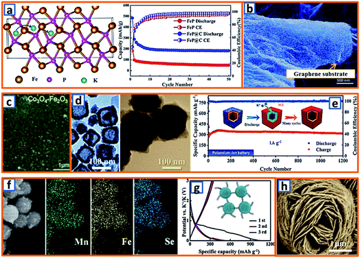 |
| | Fig. 12 Potassium storage chemistry and applications of conversion-type anodes. (a) Diffusion pathway of the K+ ions in the FeP structure, and its corresponding potassium storage performance. Reproduced with permission.18 Copyright 2019, American Chemical Society. (b) SEM image of CoS@G. Reproduced with permission.37 Copyright 2017, Wiley. (c) Surface morphology of the conversion-type Co3O4–Fe2O3 electrodes. Reproduced with permission.14 Copyright 2017, The Royal Society of Chemistry. (d) TEM of the synthesized CuxS and Cu2S@NC, and (e) the long cycling performance of Cu2S@NC. Reproduced with permission.75 Copyright 2020, American Chemical Society. (f) SEM mapping characterization and (g) discharge and charge performances of the Mn–Fe–Se/CNT composite. Reproduced with permission.91 Copyright 2019, Elsevier. (h) SEM of the flower-like VPO4 anode material. Reproduced with permission.103 Copyright 2019, The Royal Society of Chemistry. | |
3.3 Intercalation-type compound
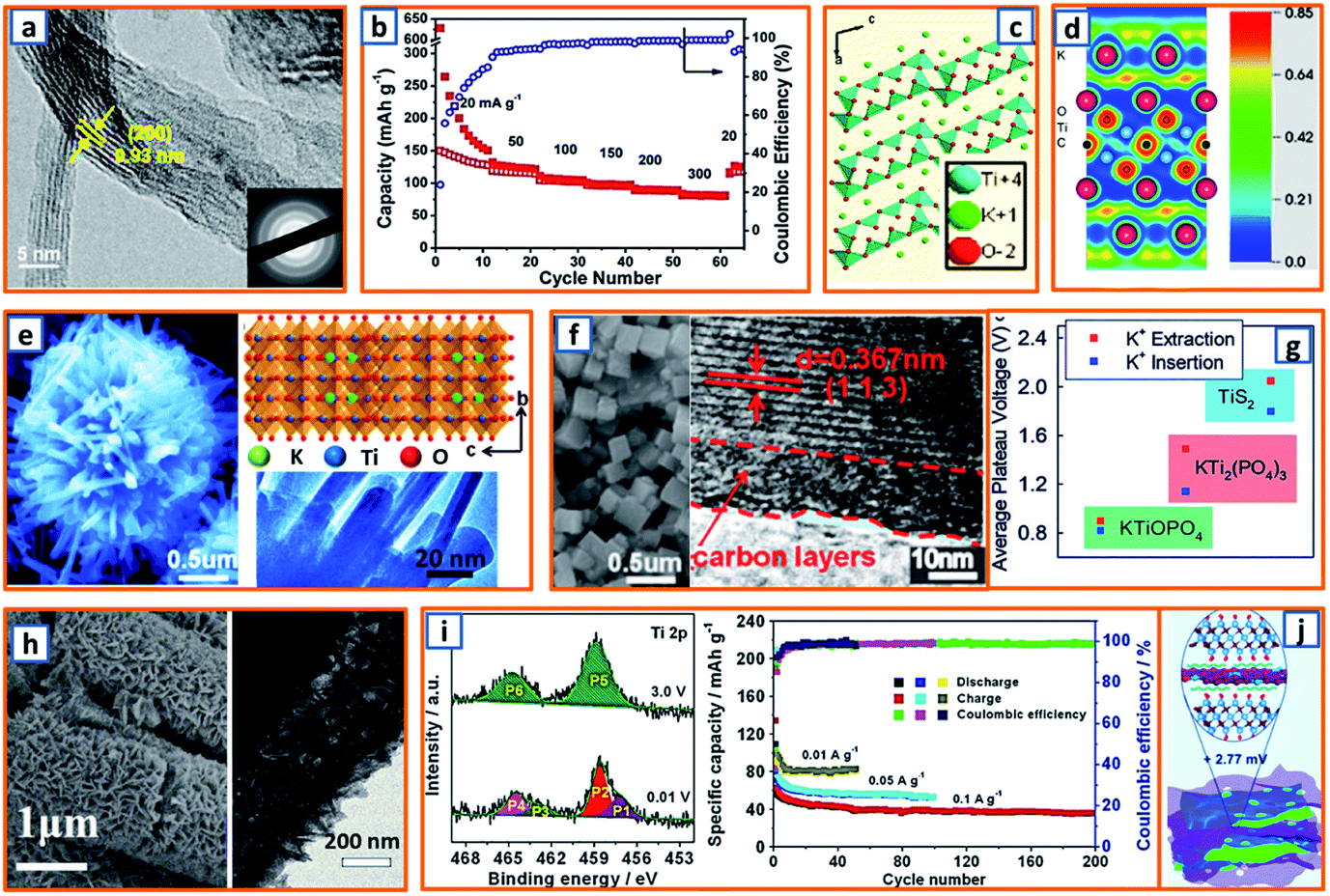
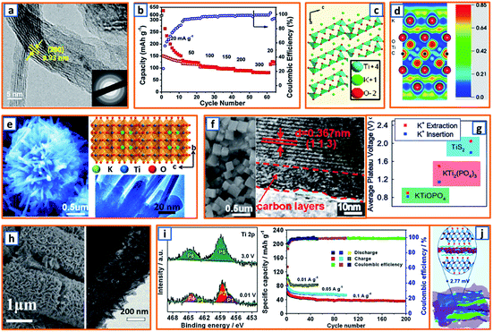
Because spinel-lithium titanate and sodium-titanate compounds have been explored as intercalation anodes for LIBs and sodium-ion batteries (SIBs),154,155 it is reasonable to develop the analogs of these compounds as an intercalation-type in KIBs. To date, most of the non-carbonaceous, intercalation-type anodes reported for KIBs are Ti-based materials. For instance, M-KTO with suitable interlayer spacing for potassium insertion has been proposed as a typical intercalation-type anode; its potassium storage mechanism is given as follows: K2Ti4O9 + 2K+ + 2e− → K4Ti4O9, during which two Ti4+ ions are reduced and accompanied by the insertion of potassium ions. In order to promote the intercalation of potassium titanate, an ultrathin nanoribbon-structured M-KTO was delicately prepared by Bao and coworkers via the simultaneous oxidation and alkalization of Ti3C2 MXene derived from HF-etched Ti3AlC2 in a mixed solution of H2O2 and KOH.11 As illustrated in Fig. 13a, the obtained M-KTO maintained a suitable interlayer spacing (0.93 nm), ultrathin thickness (<11 nm), and narrow nanoribbon width (<60 nm), which induced a superior specific capacity of 151 mA h g−1 at 50 mA g−1 and 88 mA h g−1 at a high rate of 300 mA g−1 (Fig. 13b). In addition, Brij et al. proposed a layered M-KTO with a monoclinic structure consisting of zig-zag ribbons of TiO6 octahedra; it maintained a suitable interlayer gap to accommodate K+ ions through the facile grinding of a mixture of K2CO3 and TiO2 (Fig. 13c).25 To further promote the experimental and theoretical research of K-ions in MXene, first-principles simulations were combined with select experimental measurements to elucidate their storage behavior.45 As exhibited in the electron localization functions of the (110) section for potassium (Fig. 13d), the electrons were relatively localized, which might be due to electron transfer from spherical s orbitals to the more localized nonspherical p or d orbitals. Consistent with theoretical calculations, it was verified that K+ ions are embeddable in a terminated Ti3C2 NS.45 Notably, a unique K2Ti8O17 crystal was also successfully fabricated and evaluated as an anode active material in KIB by Han's group. Compared with the large-sized bulk K2Ti8O17 prepared through a solid-state method, the novel K2Ti8O17 obtained through hydrothermal treatment and post-sintering possessed a nanorod-formed canthosphere-like morphology (Fig. 13e). In addition, by taking advantage of large interstitial spaces and open channels for K+ ion transport provided by the edge- and corner-sharing TiO6 octahedrons, the novel K2Ti8O17 anode delivered a specific discharge capacity of 110.7 mA h g−1 after 50 cycles. This study may provide valuable inspiration for the exploration of novel intercalation-type anodes. Similarly, by the hydrothermal treatment of TiO2, KH2PO4, and H3PO4, Xu's group reported a novel nanocubic KTi2(PO4)3 anode (Fig. 13f). With a 10 nm-thick carbon coating and suitable interlayer distance of 0.367 nm, the KTi2(PO4)3/C composites possessed a favorable host structure for its K-storage reaction.80 In addition, KTiOPO4 (KTP) with an inorganic-open-framework anode was reported by Sun's group.35 In contrast to the sole Ti–O–P linkage in KTi2(PO4)3, one-third of the Ti–O–P linkages in the KTP structure was substituted by the weaker Ti–O–Ti, which could lead to a lower redox potential (Fig. 13g); it not only elevated the full cell voltage but also sufficiently prevented the catastrophic K-dendrite formation.35 Hierarchical HeTiO2eC microtubes (MTs) composed of heterostructured TiO2eC NSs had also been proposed, illustrating a microtubular structure with a diameter of ca. 2.0 μm and shell thickness of approximately 400 nm (Fig. 13h). This rationally designed structure is highly beneficial for stress buffer and electrolyte diffusion during the potassium storage process. Through a similar synthesis procedure, Jiao et al. obtained nanorod-like K2Ti6O13 anode materials. In the X-ray photoelectron spectroscopy (XPS) characterization of the electrodes, the Ti3+ content was 17.80% at 0.01 V, while the peaks (P5 and P6) for the Ti 2p spectrum could be evidently assigned to Ti4+. The partial reversible redox reaction of Ti4+/Ti3+ contributed to various acceptable reversible capacities, i.e., 95.7, 83, and 53.6 mA h g−1 at 0.01, 0.05, and 0.1 A g−1, respectively (Fig. 13i).118 Moreover, self-assembled Ti3C2 MXene and N-rich porous carbon hybrids (PDDA-NPCN/Ti3C2) were reported and further applied as active materials for potassium storage (Fig. 13j).123 Owing to the electrostatic attraction-induced self-assembly, the coupled hybrids maintained a stacked structure and abundant accessible active sites, which was beneficial for potassium storage.
 |
| | Fig. 13 Potassium storage chemistry and applications of intercalation-type anodes. (a) TEM of the ultrathin nanoribbons of potassium titanate and (b) its rate performance. Reproduced with permission.11 Copyright 2017, American Chemical Society. (c) Crystal structure of the M-KTO anode. Reproduced with permission.25 Copyright 2016, The Electrochemical Society. (d) Electron localization functions of Ti2CO2 with two K layers. Reproduced with permission.45 Copyright 2014, American Chemical Society. (e) Microstructure and projection of the K2Ti8O17 structure along the [100] direction. Reproduced with permission.67 Copyright 2016, The Royal Society of Chemistry. (f) SEM of nanocubic KTi2(PO4)3 and HRTEM image of KTi2(PO4)3/C. Reproduced with permission.80 Copyright 2016, The Royal Society of Chemistry. (g) Comparison of K+-(de)intercalation in three different intercalation-type anodes. Reproduced with permission.35 Copyright 2019, Wiley. (h) Microstructure of hierarchical tubular TiO2-carbon MTs. Reproduced with permission.109 Copyright 2019, Elsevier. (i) XPS spectra of the K2Ti6O13 electrode at full potassiation (0.01 V) and depotassiation (3.0 V) states, and its corresponding potassium storage performance at various current densities. Reproduced with permission.118 Copyright 2019, Elsevier. (j) Illustration of PDDA-modified N-rich porous CNS/Ti3C2 hybrids. Reproduced with permission.123 Copyright 2020, The Royal Society of Chemistry. | |
3.4 Compound anodes with multiple potassium storage behaviors
In recent years, following the development of research, a growing number of anodes with mixed potassium storage behaviors have been reported. For example, there is a conversion–alloying reaction for SnO2 (SnO2 + 4K+ + 4e− → 2Sn + 2K2O; 23Sn + 4K+ + 4e− → 2K4Sn23);16 the CuSe anode undergoes a conversion–decomposition process (CuSe + 2K+ + 2e− → Cu + K2Se; K2Se + 2e− → 2K + Se);20 and intercalation–conversion reactions are identifiable from the potassiation of the V5S8 anode (V5S8 + K+ + e− → KV5S8; 3KV5S8 + 13K+ + 13e− → 8K2S3 + 15 V).40 In this section, mixed potassium storage behaviors are systematically organized and summarized. For instance, Hou et al. rationally anchored SnO2 on the surface of carbon foam (denoted as SnO2@CF) and applied it as a free-standing anode. Featuring a 3D conductive carbon frame and SnO2 active NPs (Fig. 14a), the as-obtained SnO2@CF with uniform elemental distribution provided an excellent potassium storage capacity, impressive cycling durability (231.7 mA h g−1 after 400 cycles at 1 A g−1) and reliable rate properties (371.4, 307.6, 247.3, and 143.5 mA h g−1 at 0.5, 1, 2, and 5 A g−1, respectively).16 To further promote the conductivity and stability of SnO2-based active materials, Luo et al. encapsulated SnO2 ultrafine NPs that were obtained by the selective etching of the copper from Cu6Sn5 by citric acid-based 3D porous carbon (SnO2@C) (Fig. 14b).41 With the assistance of a NaCl template, the obtained SnO2@C composite possessed an abundant buffer space, and the volume change during the conversion–alloying reaction could be sufficiently accommodated, leading to a high reversible capacity (270.3 mA h g−1 after 200 cycles) and excellent rate performance (144.6 mA h g−1 at 2 A g−1) (Fig. 14c). The SnO electrode material also possesses a high reaction activity.59 The electrode disintegration induced by the significant volume change rapidly deteriorated the comparative Sn electrode, while the SnO electrode exhibited a durable performance (80% retention after 30 cycles) without cracking nor peeling off (Fig. 14d). In this work, the SnO-based electrode exhibited beneficial self-suppressed properties and improved potential for potassium storage. The addition of graphene could effectively improve the conductivity of Sn-based anodes, according to Zhang's report.74 Specifically, GO in dimethylformamide (DMF) was mixed with a solution containing SnCl2, polyacrylonitrile, and polymethyl methacrylate. After electrospinning and calcination in a furnace, the graphene-promoted SnO2–G–C composite was obtained (Fig. 14e) and was established to exhibit enhanced electrical conductivity (Fig. 14f). With the assistance of thioacetamide, a structurally engineered novel SnS2/graphene composite was developed by Wan's group.90 The obtained SnS2/graphene with a sheet-stacking porous architecture (Fig. 14g) could effectively buffer the mechanical stress of small SnS2 NPs with sizes less than 5 nm, which induced a high reversible capacity (610 mA h g−1) and excellent rate capability (approximately 290 mA h g−1 at 2 A g−1) (Fig. 14h). In this work, the rational size-confinement strategy was systematically investigated to provide sufficient reactive sites and facilitate ion and electron transfer during the cycling process. Another SnS2–graphene composite with a self-generated carbon network inside and a GO layer outside was also synthesized via the sulfuration of Sn@C particles (Fig. 14i).104 Owing to the synergistic effect of the inner carbon as a fast electronic conductor and the graphene shell as an effective inhibitor of the growth of SnS2, a high reversible capacity of 499.4 mA h g−1 (0.05 A g−1) and good cycling durability (298.1 mA h g−1 after 500 cycles at 0.5 A g−1) could be achieved. This work further strengthened the understanding of SnS2-based anodes in KIBs. With desirable potassium storage potential, bismuth oxyhalides consisting of square-shaped nanoflakes with apparent corners, smooth surfaces, and thicknesses of 35–40 nm were investigated by Lei and his coworkers (Fig. 14j).114 In the visualization of the atomic arrangement in Fig. 14k, the minimum unit in the (001) plane was square-shaped (white lines). When tested in a KIB, the BiOCl nanoflake assemblies demonstrated a desirable reversible capacity (367 mA h g−1). This work could significantly expand the exploration of bismuth-based compounds for KIBs.
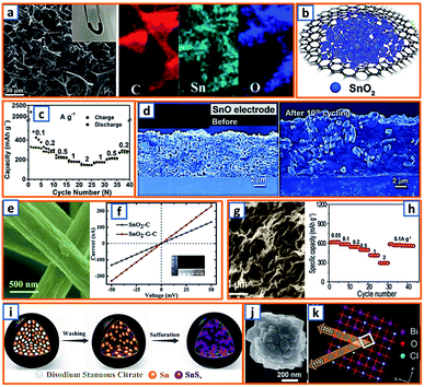 |
| | Fig. 14 Potassium storage chemistry and applications of anodes with a conversion–alloy mechanism. (a) SEM images and elemental mapping of SnO2@CF with the photograph of the freestanding SnO2@CF inserted. Reproduced with permission.16 Copyright 2020, The Royal Society of Chemistry. (b) Schematic illustration of the 3D SnO2@C and (c) its corresponding rate performance. Reproduced with permission.41 Copyright 2019, Elsevier. (d) SEM of the SnO electrode before and after cycling without cracks recognized. Reproduced with permission.59 Copyright 2018, American Chemical Society. (e) Morphology of SnO2–G–C nanofibers and (f) its electrical conductivity measurement. Reproduced with permission.74 Copyright 2018, Elsevier. (g) Morphology and (h) rate capabilities of the SnS2/graphene nanocomposite. Reproduced with permission.90 Copyright 2019, Elsevier. (i) Illustration of the synthesized SnS2@C@rGO as the anode in a KIB. Reproduced with permission.104 Copyright 2019, Wiley. (j) SEM and (k) schematic diagram of the crystal structure of the BiOCl anode material. Reproduced with permission.114 Copyright 2019, The Royal Society of Chemistry. | |
Subtle structural engineering with a SnS2-based anode was speculated to be an effective way to enhance electrode kinetics and integrity. To validate this hypothesis, Xia et al. successfully prepared few-layered SnS2 NSs supported on rGO, and investigated their electrochemical performance in KIBs (Fig. 15a), wherein SnS2 underwent sequential conversion (SnS2 to Sn) and alloying (Sn to K4Sn23, KSn) reactions during K-ion storage.5 As rational hybridization enabled fast electron/ionic transportation and effective accommodation for volume variation, this anode possessed an excellent potassium storage reversible capacity (448 mA h g−1), and further verified the significant effectiveness of structural modification. Additionally, nanocrystalline SnS2 was fabricated on the surface of graphene to minimize the effects related to possible volume changes during cycling (Fig. 15b). Apparently, the reversible capacities recorded at various current densities were highly desirable, exhibiting a high retention of 120 mA h g−1 at 2 A g−1. Heteroatom-modified carbon-supported SnS2 NSs were also synthesized using tetraphenyltin as the Sn source, as well as C and thiourea as the N and S sources.60 The S–Sn–S layers in SnS2 with a CdI2-type structure were formed by strong Sn–S bonds and connected by van der Waals forces (Fig. 15c). The detailed potassium storage properties were also elucidated, exhibiting a high reversible capacity (614.8 mA h g−1) and long cycling stability (70.9% over 200 cycles). In order to further promote the reliability of Sb-based KIB anodes, Chen's group demonstrated a robust self-supported anode by integrating Sb2S3 NPs with S, N-codoped graphene (Fig. 15d).73 As shown in Fig. 15e, there were evident plateaus at 4.1–4.6 V for the cathode (KVPO4F–C) and 0.3–0.8 V for the anode (Sb2S3–SNG), indicating that the output voltage of the assembled full cell could be higher than 2 V. Besides, the potassium storage capacity was 548 mA h g−1 at 20 mA g−1, which originated from the suppressed volume swelling and electrode affinity derived from the rational structural design.73 Through peroxide-containing precursors (SbOOH–GO), Lakshmi's group probed and investigated the electrochemical reactivity of Sb2S3–rGO electrodes (Fig. 15f).93 When tested in a KIB cell, there was a high depotassiation capacity (633 mA h g−1) (Fig. 15g), and the reaction mechanism of the Sb2S3 with potassium was also analyzed via post-cycling XRD and in situ transmission electron microscopy (TEM), thereby unveiling the presence of antimony alloys, potassium polysulphides, and a conversion–alloying reaction mechanism. In addition, the Sn phase and K3P could be identified in the fully potassiated state by Ci et al. in hierarchically porous carbon-supported Sn4P3, which was prepared via the thorough phosphorization of the Na2CO3-templated Sn@C composite (Fig. 15h).105 This work verifies the reliability of the conversion reaction and alloying behavior, as well as facilitates the accelerated development of a conversion–alloy-type KIB anode.
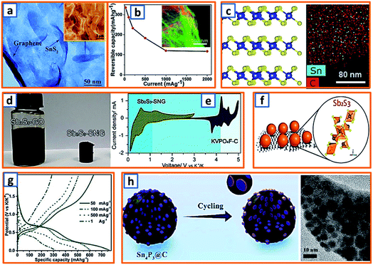 |
| | Fig. 15 Potassium storage chemistry and applications of anodes with conversion–alloy mechanism. (a) Microstructure of obtained SnS2@rGO composite. Reproduced with permission.5 Copyright 2019, Wiley. (b) Electrochemical performance of SnS2–rGO composite with an energy-filtered TEM image (color scheme: red-sulfur, green-carbon) inserted. Reproduced with permission.38 Copyright 2017, The Royal Society of Chemistry. (c) Schematic crystal structure of SnS2 in N, S–C/SnS2 NSs, and its corresponding elemental mappings. Reproduced with permission.60 Copyright 2020, Elsevier. (d) Photographs of the Sb2S3–GO precursor solution and Sb2S3–SNG composite and (e) CV curves of Sb2S3–SNG/KVPO4F–C full cells. Reproduced with permission.73 Copyright 2017, Springer. (f) Schematic representation of the nanocrystalline Sb2S3 coated by rGO NSs, and (g) charge/discharge curves at various current densities. Reproduced with permission.93 Copyright 2020, The Royal Society of Chemistry. (h) Illustration of the potassium storage behavior of the Sn4P3@C active material. Reproduced with permission.105 Copyright 2019, Elsevier. | |
In contrast to the well-known hexagonal phase, Du et al., for the first time, proposed a facile preparation of cubic phase CuSe.20 Typically, hydrazine hydrate, Na2SO3, and copper sulfate were mixed and continuously stirred before the dispersion of the Se precursor. After a mild reaction for 30 min, the as-prepared CuSe precipitate was obtained, and it exhibited a crystal-pillar-like morphology because of the intensive self-assembly (Fig. 16a). To gain a deeper understanding of the potassium storage behavior, in situ XRD analysis was conducted; with the increasing potassium content, the CuSe disappeared gradually, accompanied by the appearance of new phases. It is noteworthy that the signals located at 27.4°, 35.6°, and 36.9° could be indexed based on Se, and the peak at 43.6° was derived from Cu formation at low terminal voltage, which should not be explained by the pure conversion reaction (Fig. 16b). Considering the intrinsic metastability of K2Se, decomposition (K2Se + 2e− → 2K + Se) might occur during the potassiation process at 0.01 V.20 When the as-obtained CuSe was applied as a KIB anode, several notable phenomena were observed. For example, the plateau-like behavior could only be identified in the initial several cycles, and a slope-like tendency was observed as the charge/discharge reactions proceeded, which was ascribed to electrode amorphization (Fig. 16c). Significantly, an ultrahigh capacity retention of 92.6% as compared with its initial capacity could be achieved at a current density of 2 A g−1 even after 300 cycles (Fig. 16d). This suggests that the robust self-assembled CuSe can be a promising KIB anode candidate through the conversion–decomposition process.
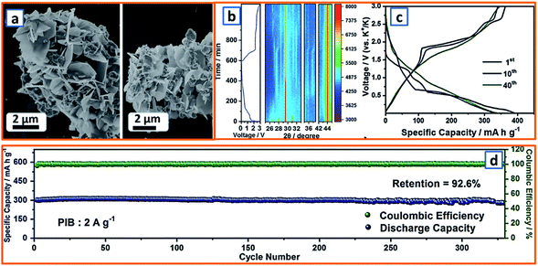 |
| | Fig. 16 Potassium storage chemistry and applications of conversion–decomposition-type anodes. (a) Morphology of crystal-pillar-like CuSe. (b) In situ XRD patterns of the CuSe electrode obtained during the first electrochemical cycle. (c) Charge–discharge curves and (d) long cycling performance of CuSe electrodes in KIB. Reproduced with permission.20 Copyright 2019, Wiley. | |
To stress the sluggish kinetics induced by the large K+ ion radii, Zhang et al. rationally designed and prepared NS-assembled layered Ti3C2Tx MXene/MoS2 composites.15 Firstly, Ti3AlC2 MAX was etched with a concentrated HF solution, forming an accordion-like structure (Fig. 17a). After ultrasonication in a C6H12O6 solution, the as-obtained MXene was mixed and heat-treated together with Na2MoO4 and CH4N2S, resulting in the uniform vertical anchoring of MoS2 in the conductive MXene substrate (Fig. 17b). This delicately designed structure could not only induce fast ion and electron transportation but also significantly prevent the restacking of MXene sheets. Besides, Li's group also found a way to achieve rapid and desirable potassium storage by wrapping a hollow carbon sphere with few-layered V5S8 NSs, which was induced by the facile transformation of VS4@C obtained through a gradual reaction between thioacetamide and vanadium precursor (Fig. 17c).40 To evaluate the energy barriers for the diffusion of K+ ions, nudged elastic band calculations were carried out. Compared with the high energy barrier in VS4 (0.45 eV), V5S8, with an energy barrier of 0.16 V, had a much lower migration resistance for K-ions (Fig. 17d), thereby enabling a high rate capability. Nevertheless, the cycling performance was not sufficiently stable, with 360 and 190 mA h g−1 achieved after 500 and 1000 cycles. With the aim of further enhancing the cycling stability of intercalation–conversion type KIB anodes, Guan's group fabricated a yolk–shell FeS2@C structure on a graphene matrix.61 During the potassium storage process, K-ion intercalation occurred before its conversion into Fe and K2S (Fig. 17e). In addition to the graphene-enhanced conductivity, the proposed yolk–shell microstructure could provide an interior void space for expansion accommodation and prevent the aggregation of FeS2 active NPs. The construction of porous FeS2 NPs on a graphene matrix followed by additional carbon coating (rGO@p-FeS2@C) was also adopted by Guan et al. as a feasible way to facilitate the practical application of FeS2 (Fig. 17f).77 Benefiting from a tough carbon network, protective carbon layer, and abundant interior void space, the fabricated 2D FeS2–C architecture, as expected, delivered a high reversible capacity of 500 mA h g−1 (Fig. 17g). In addition, it provided a superior rate capacity of 298 mA h g−1 at 2 A g−1, further consolidating its practical potential. Additionally, MoSe2 was also proposed by Yu and coworkers as a novel KIB anode candidate.94 Before anode application, they first coated the MoSe2 active particles with a N-modified uniform carbon layer, forming a nanosphere structure with numerous NSs stretching out (Fig. 17h). During a typical cyclic voltammetry (CV) measurement, two main cathodic peaks could be identified at 1.06 and 1.48 V, corresponding to the insertion of K+ ions into the MoSe2 interlayers to form KxMoSe2 and the conversion of KxMoSe2 to K5Se3 and Mo metal.94 When tested in KIBs, it delivered an impressive rate performance and good cycling durability (258.0 mA h g−1 after 300 cycles) (Fig. 17i), which could be ascribed to the impeded aggregation, optimized electrode integrity, and promoted conductivity.
 |
| | Fig. 17 Potassium storage chemistry and applications of intercalation–conversion-type anodes. (a) Microstructure of MXene and (b) subsequent MXene/MoS2 composite. Reproduced with permission.15 Copyright 2019, Elsevier. (c) Illustration of VS4@C precursor and final V5S8@C product, and (d) side view of K atom diffusion pathways in V5S8. Reproduced with permission.40 Copyright 2019, American Chemical Society. (e) Potassium storage reaction mechanism of FeS2 anode, disclosing its reversible intercalation/deintercalation and conversion reactions during cycles. Reproduced with permission.61 Copyright 2018, Wiley. (f) Synthesis of the rGO@p-FeS2@C composite and (g) discharge/charge profiles of its initial three cycles. Reproduced with permission.77 Copyright 2019, Elsevier. (h) Element mapping and (i) cycling performance of MoSe2/N–C anode material. Reproduced with permission.94 Copyright 2018, Wiley. | |
3.5 Organic anodes
Organic anodes with several advantages, such as tunable redox properties, low weight, and mechanical flexibility, could effectively expand the range of choices for KIB battery fabrication.156 Moreover, the redox reactions of organic active materials are less hindered by the large ionic size of K ions owing to their soft nature, which has attracted considerable attention. An organic compound, azobenzene-4,4-dicarboxylic acid potassium salts (ADAPTS), was developed by Wang et al. by neutralizing the azobenzene-4,4-dicarboxylic acid with potassium hydroxide, wherein the introduced carboxylate groups could remarkably minimize the dissolution of ADAPTS in organic electrolytes, as the polarity of the organic active materials was rationally enhanced.12 Besides, the signals from the π electrons were pronounced in the low energy loss regime of the electron energy loss spectroscopy spectra, whereas both π and σ electrons could be observed in the high energy loss regime (Fig. 18a), thereby enabling a fast charge/discharge capability based on the enhanced electron transfer by the abundant delocalized π electrons. With the azo group (N![[double bond, length as m-dash]](https://www.rsc.org/images/entities/char_e001.gif) N) as the redox center, ADAPTS-based anodes demonstrated a desirable capacity of 113 mA h g−1 and a capacity retention of 81% after 80 cycles, thereby validating its KIB potential. To promote the cycling integrity of organic anodes, Fan et al. exploited potassium perylene-tetracarboxylate (K4PTC) as a new candidate.29 With a two-electron redox behavior, the optimized K4PTC, as expected, retained a high reversible capacity of ca. 100 mA h g−1 (Fig. 18b) and long cycling stability (2500 cycles). Furthermore, two small organic molecules, namely potassium terephthalate (K2TP) and potassium 2,5-pyridinedicarboxylate (K2PC), were explored as reliable organic KIB anodes by Li et al., thereby exhibiting apparent and reversible reaction platforms due to the redox behavior of organic para-aromatic dicarboxylates.51 As illustrated in Fig. 18c, when charging/discharging at 0.2C, the as-obtained K2TP and K2PC could provide a stable capacity of 181 and 190 mA h g−1, respectively, which efficiently contributed to the development of rocking-chair KIBs. Then, they further investigated the electrochemical behavior of cobalt terephthalate (CoTP) as an organic anode in KIBs.72 During the initial cycle, the Co element of CoTP could be irreversibly reduced from Co2+ to Co0, resulting in the formation of K2TP in the subsequent cycles. After the cooperation of the efficiently conductive super P, it retained a satisfactory specific capacity of 112 mA h g−1 after 200 cycles under a current density of 60 mA g−1 (Fig. 18d), which was comparable or even superior to some inorganic anodes.72 Owing to the economical and eco-friendly nature of organic anodes, Pan et al. also developed 3,4,9,10-perylenetetracarboxylic diimide (PTCDI), an important organic semiconductor, as a high-rate KIB anode.86 Notably, a six-electron storage mechanism was proposed according to the records in the X-ray characterization (Fig. 18e), possessing a high specific capacity of 310 mA h g−1 at 0.5 A g−1 with a remarkable rate performance.86 Notably, high electron transfer and insolubility induced by the intrinsic p–p aromatic stacking could also be appealing advantages of PTCDI-based anodes.
N) as the redox center, ADAPTS-based anodes demonstrated a desirable capacity of 113 mA h g−1 and a capacity retention of 81% after 80 cycles, thereby validating its KIB potential. To promote the cycling integrity of organic anodes, Fan et al. exploited potassium perylene-tetracarboxylate (K4PTC) as a new candidate.29 With a two-electron redox behavior, the optimized K4PTC, as expected, retained a high reversible capacity of ca. 100 mA h g−1 (Fig. 18b) and long cycling stability (2500 cycles). Furthermore, two small organic molecules, namely potassium terephthalate (K2TP) and potassium 2,5-pyridinedicarboxylate (K2PC), were explored as reliable organic KIB anodes by Li et al., thereby exhibiting apparent and reversible reaction platforms due to the redox behavior of organic para-aromatic dicarboxylates.51 As illustrated in Fig. 18c, when charging/discharging at 0.2C, the as-obtained K2TP and K2PC could provide a stable capacity of 181 and 190 mA h g−1, respectively, which efficiently contributed to the development of rocking-chair KIBs. Then, they further investigated the electrochemical behavior of cobalt terephthalate (CoTP) as an organic anode in KIBs.72 During the initial cycle, the Co element of CoTP could be irreversibly reduced from Co2+ to Co0, resulting in the formation of K2TP in the subsequent cycles. After the cooperation of the efficiently conductive super P, it retained a satisfactory specific capacity of 112 mA h g−1 after 200 cycles under a current density of 60 mA g−1 (Fig. 18d), which was comparable or even superior to some inorganic anodes.72 Owing to the economical and eco-friendly nature of organic anodes, Pan et al. also developed 3,4,9,10-perylenetetracarboxylic diimide (PTCDI), an important organic semiconductor, as a high-rate KIB anode.86 Notably, a six-electron storage mechanism was proposed according to the records in the X-ray characterization (Fig. 18e), possessing a high specific capacity of 310 mA h g−1 at 0.5 A g−1 with a remarkable rate performance.86 Notably, high electron transfer and insolubility induced by the intrinsic p–p aromatic stacking could also be appealing advantages of PTCDI-based anodes.
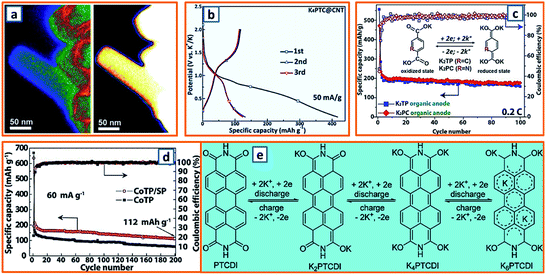 |
| | Fig. 18 Potassium storage chemistry and applications of organic anodes. (a) EELS spectra of ADAPTS organic compound at low (left) and high (right) energy loss regimes. Reproduced with permission.12 Copyright 2018, Wiley. (b) Charge–discharge curves of K4PTC@CNT anode during the three initial cycles. Reproduced with permission.29 Copyright 2019, The Royal Society of Chemistry. (c) Long cycle profiles of K2TP and K2PC organic anodes for 100 cycles. Reproduced with permission.51 Copyright 2017, Elsevier. (d) Cycling performance of CoTP and CoTP/super P in K-ion cells (60 mA g−1). Reproduced with permission.72 Copyright 2017, Elsevier. (e) Possible six-electron storage mechanism for organic PTCDI anode. Reproduced with permission.86 Copyright 2019, The Royal Society of Chemistry. | |
3.6 Carbonaceous anodes
Owing to the development of LIB applications, graphite has been considerably explored in KIBs and showed reliable potassium storage performance. Liu and coworkers further unveiled the potassium storage mechanism of graphite by correlating the real-time electrochemical K+ intercalation/deintercalation process with structure/component evolution.17 Attempting to track the structural evolution during potassium intercalation, a focused ion beam lift-out strategy was utilized for specimen fabrication, which started with trenching, followed by lifting-out and welding, and finished with milling. This finally led to the achievement of a transparent 50 nm-thick graphite foam (Fig. 19a). After characterization, the XRD patterns derived from DFT calculations matched well with the experimental results, thereby further promoting the determination of the stoichiometry of various K-GIC stages (Fig. 19b). Thus, the staging transition of K-GICs was concluded: C ↔ stage 5 (KC60) ↔ stage 4 (KC48) ↔ stage 3 (KC36) ↔ stage 2 (KC24/KC16) ↔ stage 1 (KC8). Although graphite has several merits as a KIB anode, including low cost and source abundance, it always suffers from limited cycle time and inferior performance. To resolve these problems, Lu et al. applied concentrated KN(SO2F)2/ethyl methyl carbonate (KFSI![[thin space (1/6-em)]](https://www.rsc.org/images/entities/char_2009.gif) :EMC, 1:2.5, molar ratio) as the electrolyte to enhance the formation of a tough inorganic-rich passivation layer on the graphite and promote the electrode integrity during potassiation/depotassiation.33 Unexpectedly, the optimized graphite anode could operate for over 2000 cycles (running time of over 17 months) with negligible deterioration (Fig. 19c). Furthermore, Wang et al. revisited graphite as KIB anodes and comparatively investigated its electrochemical performance in carbonate-and ether-based electrolytes.58 Remarkably, graphite, with ABA stacking and a layer distance of 3.36 Å (Fig. 19d), exhibited a totally different behavior in these two electrolytes. Fig. 19e shows the distinct electrochemical response. Specifically, a DME electrolyte with a larger electron donation number than the EC exhibited a higher binding energy with K-ions, and the formed K+-DME complexes with small Stokes radii could co-intercalate into graphite with suppressed volume swell, low diffusion resistance, and high initial coulombic efficiency.58 Moreover, an enhanced cycling durability for 700 cycles could be successfully achieved for a graphite anode in a DME-based electrolyte (Fig. 19f). This work sufficiently addressed the importance of graphite–electrolyte compatibility in boosting potassium storage stability and capability.
:EMC, 1:2.5, molar ratio) as the electrolyte to enhance the formation of a tough inorganic-rich passivation layer on the graphite and promote the electrode integrity during potassiation/depotassiation.33 Unexpectedly, the optimized graphite anode could operate for over 2000 cycles (running time of over 17 months) with negligible deterioration (Fig. 19c). Furthermore, Wang et al. revisited graphite as KIB anodes and comparatively investigated its electrochemical performance in carbonate-and ether-based electrolytes.58 Remarkably, graphite, with ABA stacking and a layer distance of 3.36 Å (Fig. 19d), exhibited a totally different behavior in these two electrolytes. Fig. 19e shows the distinct electrochemical response. Specifically, a DME electrolyte with a larger electron donation number than the EC exhibited a higher binding energy with K-ions, and the formed K+-DME complexes with small Stokes radii could co-intercalate into graphite with suppressed volume swell, low diffusion resistance, and high initial coulombic efficiency.58 Moreover, an enhanced cycling durability for 700 cycles could be successfully achieved for a graphite anode in a DME-based electrolyte (Fig. 19f). This work sufficiently addressed the importance of graphite–electrolyte compatibility in boosting potassium storage stability and capability.
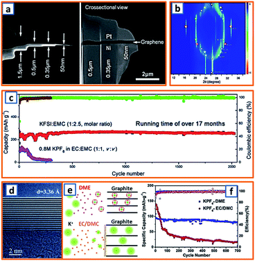 |
| | Fig. 19 Potassium storage chemistry and applications of graphite anodes. (a) Focused ion beam-based GB sample preparation (left) and its cross-sectional view (right). (b) XRD patterns derived from DFT calculations for KCx models. Reproduced with permission.17 Copyright 2019, Wiley. (c) Cycling performance of graphite with two different electrolytes in KIB cells. Reproduced with permission.33 Copyright 2019, Wiley. (d) HRTEM image, (e) response in different electrolytes and (f) cycling performance of graphite anode material. Reproduced with permission.58 Copyright 2018, Elsevier. | |
In addition to graphite, various non-graphitic carbon materials could also provide impressive potassium storage capability due to sufficient surface areas, developed porosity, and abundant active sites.157 Recently, Zhuang et al. fabricated a type of functional phosphorus and oxygen dual-doped graphene (PODG) using triphenylphosphine and graphite oxide as precursors.6 After sintering-assisted heteroatom doping, a transparent folded silk-like structure could be evidently identified (Fig. 20a). Owing to the enhanced chemisorption of potassium ions on conductive PODG and good accommodation of volume deformation, the as-proposed PODG displayed a high specific capacity of 474 mA h g−1 at a current density of 50 mA g−1. Nevertheless, the highly reactive surface and flexibility generally results in excessive electrolyte consumption and low coulombic efficiency. To address the aforementioned problems, Liu's group successfully prepared a special crystal carbon shell for graphene microspheres, denoted as CCGM.39 During the charge/discharge process, the erosion reactions could be hindered by the robust armor, i.e., the crystal carbon shell, which acted as a physical barrier to reduce the direct anode–electrolyte contact (Fig. 20b). Additionally, after the initial cycle, a uniform electrode passivation layer was formed on the outmost surface of CCGM, further promoting a stable K-ion transmission.39 Sulfur modification could also improve the electrochemical performance of hollow carbon, according to the exploration of Mitlin and coworkers.1 As can be seen in Fig. 20c, intact hollow carbon spheres could be obtained; there was a uniform size distribution (ca. 400 nm in diameter) and wall thickness (40 nm) (Fig. 20d). The rational designed architecture combines nanoscale ionic diffusion and chemical C/S bonds, which can sufficiently suppress capacity fading and potassium loss. To achieve an ultrastable cycling with enhanced capacity, Xiong et al. further proposed chemically activated hollow carbon nanospheres via self-assembly of resorcinol formaldehyde on the surface of SiO2 nanospheres.22 After template removal and repeated pyrolysis, activated hollow carbon nanospheres (AHCSs) could be collected. As shown in Fig. 20e, the thoroughly activated microstructure and buffer-sufficient design enabled AHCS an ultralong durability for 5000 cycles and improved reversible capacity compared with inactivated carbon spheres. Sun et al. further explored highly wrinkled carbon tubes as novel anode materials in KIBs. Through a nickel-assisted solid-state approach and nitrate acid treatment, few-layered hollow carbon tubes with unique wrinkle morphology and heteroatom modification were obtained based on a possible two-step wrinkle formation mechanism, including catalyst removal induced wrinkles and oxygen-containing functional groups induced wrinkles (Fig. 20f).19 Besides, the electrochemical performance of the KIB half cell (Fig. 20g) was also recorded, illustrating an impressive capacity of 231 mA h g−1 even at 2000 mA g−1, which is remarkably superior to that of the traditional graphite anode (Fig. 20h). Yu et al. fabricated 3D interconnected nitrogen-doped carbon (N-HPC) by carbonizing ordered macroporous ZIF-8. Typically, highly ordered 3D polystyrene spheres (PSs) originated by filtration of PS solution were applied as the template to assemble ordered and self-assembled ZIF-8 precursor induced by ammonium hydroxide.21 After PS removal and carbonization at high temperature, hierarchical porous N-HPC could be collected (Fig. 21a), demonstrating a highly stable and enhanced potassium storage capability (292 mA h g−1 after 400 cycles at 0.1 A g−1) compared with bulk NPC prepared without a PS template (116 mA h g−1 after 200 cycles) (Fig. 21b). Similarly, hierarchically nitrogen-doped porous carbon (HNPC) was also fabricated using sodium citrate and urea as the carbon and nitrogen sources, respectively.42 After transformation from Na+ to Na2CO3, the template could be easily washed away, leaving developed porosity (Fig. 21c). The density of states (DOSs) of different carbon structures were also analyzed (Fig. 21d), revealing the increased DOS around the Fermi level of defective and nitrogen-doped carbon and their higher affinity to K atoms. Thus, it was reasonable for HNPC to achieve a high reversible capacity of 384.2 mA h g−1 after 500 cycles.42 Electrospun carbon fibers with sufficient buffer, large surface area, and reliable mechanical strength attracted the interest of Xing and his coworkers. After stirring polyacrylonitrile in N, N-dimethylformamide for 12 h, the homogeneous precursor solution was stretched into an electrospun nanofiber. Through calcination at ultrahigh temperature, the self-standing high-temperature graphitized CNF was then obtainable, exhibiting a relatively rough surface and superior flexibility (Fig. 21e). Moreover, stacks of ordered graphitic layers with an interlayer spacing of approximately 0.340 nm could further validate the long-term cyclic stability. Based on the ordered 1D pores of covalent organic frameworks (COFs), Wang et al. proposed a unique COF-guest chemistry and converted COF into porous carbon with multilevel hierarchy and porosity control.76 During the carbonization process of organic precursors, abundant gaseous products derived from the decomposition process could enlarge the interface space to some extent and create micro/meso/macro-porosity (Fig. 21f). As shown in Fig. 21g, when ammonium hexafluorophosphate (AHF) was used as the guest chemical, the degree of graphitization of the obtained carbon (red curve) decreased, thereby supplying more active sites for potassium storage. Additionally, the high value utilization of low-cost petroleum coke in KIBs was explored by Sun's group, during which N-abundant carbon nitride was selected as both a nitrogen source and template with petroleum coke uniformly dispersed inside.92 Because the selected template could decompose at high temperatures, time-consuming and expensive template removal was avoided before the collection of final nitrogen-doped porous CNSs (N-PCSs), which delivered a high specific capacity of 206 mA h g−1 at 1000 mA g−1 (Fig. 21h). Unlike graphitic materials, disordered carbonaceous materials have a reduced risk of potassium plating, especially at high current densities. However, for some graphene-based KIB anodes, the cost of production is relatively high, and the volumetric energy density is comparatively low. Additionally, although non-graphitic materials could exhibit prolonged cycle life, the undesirable coulombic efficiency in the initial cycle should not be neglected. Various carbonaceous anodes are described in Table 3 and corresponding comparison of typical features of different KIB anodes are also briefly summarized in Table 4.
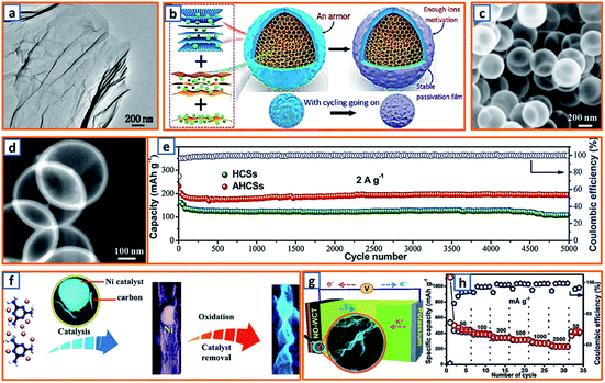 |
| | Fig. 20 Potassium storage chemistry and applications of non-graphite carbonaceous anodes. (a) Microstructure of phosphorus and oxygen dual-doped graphene anode. Reproduced with permission.6 Copyright 2017, The Royal Society of Chemistry. (b) Schematic diagram of the hybrid potassium storage route and the protection barrier formation on crystal carbon@graphene microsphere during the cycling process. Reproduced with permission.39 Copyright 2019, American Chemical Society. (c) SEM images of sulfur-grafted carbon material with (d) hollow sphere morphology. Reproduced with permission.1 Copyright 2019, Wiley. (e) Long cycling performance of the hollow carbon nanospheres and activated hollow carbon nanospheres at 2 A g−1. Reproduced with permission.22 Copyright 2018, The Royal Society of Chemistry. (f) Two-step wrinkle formation mechanism of carbon tube-based anode, (g) illustration of assembled K-ion cell and (h) its corresponding rate performance. Reproduced with permission.19 Copyright 2019, The Royal Society of Chemistry. | |
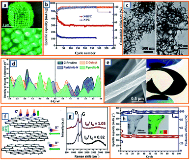 |
| | Fig. 21 Potassium storage chemistry and applications of non-graphite carbonaceous anodes. (a) Morphology of 3D interconnected nitrogen-doped hierarchical porous carbon and (b) its cycling performance. Reproduced with permission.21 Copyright 2019, American Chemical Society. (c) Microstructure of nitrogen-doped porous carbon and (d) density of states in different carbon structures. Reproduced with permission.42 Copyright 2018, Wiley. (e) SEM and photograph images of highly graphitized carbon nanofibers. Reproduced with permission.43 Copyright 2020, Elsevier. (f) Illustration of tri-doped carbon for KIB from AHF@COF and (g) its Raman spectrum. Reproduced with permission.76 Copyright 2020, Wiley. (h) Potassium storage capability of nitrogen-rich porous CNSs. Reproduced with permission.92 Copyright 2018, The Royal Society of Chemistry. | |
Table 3 The performance of typical carbonaceous anodes in potassium ion batteries
| Electrode material |
ICE |
Capacity |
Current density |
Cut voltage |
Retention |
Ref. |
| Sulfur-grafted hollow carbon spheres |
∼53% |
202 mA h g−1 |
1.5 A g−1 |
0.01–3.0 V |
∼67%/1000 cycles |
1
|
| Activated hollow carbon nanosphere |
44.2% |
370.2 mA h g−1 |
200 mA g−1 |
0.01–3.0 V |
∼80.4%/5000 cycles |
22
|
| HG-CNFs |
57% |
260 mA h g−1 |
0.1C |
0.01–3.0 V |
96.7%/400 cycles |
43
|
| P, O-doped graphene |
22.6% |
474 mA h g−1 |
50 mA g−1 |
0.01–3.0 V |
∼66.7%/50 cycles |
6
|
| Carbon@graphene microsphere |
— |
290 mA h g−1 |
100 mA g−1 |
0.01–3.0 V |
99.4%/3200 cycles |
39
|
| N–carbon nanosheet |
∼25% |
206 mA h g−1 |
1000 mA g−1 |
0.01–3.0 V |
∼74%/100 cycles |
92
|
| AHF@COF1000 |
44.6% |
186 mA h g−1 |
1000 mA g−1 |
0–3.0 V |
86.7%/300 cycles |
76
|
| Wrinkled carbon tube |
47.3% |
365 mA h g−1 |
100 mA g−1 |
0.01–3.0 V |
∼90%/150 cycles |
19
|
| 3D N-HPC |
∼60% |
292 mA h g−1 |
100 mA g−1 |
0.01–3.0 V |
67%/400 cycles |
21
|
| Hierarchically NPC |
43.1% |
384.2 mA h g−1 |
100 mA g−1 |
0.01–3.0 V |
89.2%/500 cycles |
42
|
| O, S-doped hard carbon |
46.4% |
409 mA h g−1 |
100 mA g−1 |
0.01–2.0 V |
∼80%/500 cycles |
131
|
| 3D-NTC750 |
61% |
606 mA h g−1 |
50 mA g−1 |
0.01–3.0 V |
93%/500 cycles |
111
|
| Nitrogen-doped carbon microsphere |
73% |
328 mA h g−1 |
100 mA g−1 |
0.01–3.0 V |
78%/1900 cycles |
134
|
| Hard–soft composite carbon |
76% |
260 mA h g−1 |
28 mA g−1 |
0.01–2.0 V |
89%/440 cycles |
136
|
| Loofah-derived carbon |
∼40% |
150 mA h g−1 |
100 mA g−1 |
0.01–3.0 V |
50%/400 cycles |
137
|
| Oxygen-rich carbon microsphere |
27.6% |
279 mA h g−1 |
28 mA g−1 |
0.01–2.0 V |
∼61%/900 cycles |
100
|
| Milled graphite |
61% |
210 mA h g−1 |
25 mA g−1 |
0.01–1.5 V |
65%/100 cycles |
23
|
| Commercial expanded graphite |
∼82% |
263 mA h g−1 |
10 mA g−1 |
0.01–3.0 V |
∼105%/200 cycles |
140
|
| Graphite |
87.4% |
90 mA h g−1 |
140 mA g−1 |
0.01–2.0 V |
∼88%/700 cycles |
58
|
Table 4 Comparison of the typical features of different KIB anodes
| Type |
Advantages |
Disadvantages |
| Alloying-type anode |
High potassium storage capability |
Huge volume change; side reactions; poor cycling stability |
| Intercalation-type compound |
Enhanced initial coulombic efficiency; impressive working stability |
Low specific capacity; high working voltage |
| Conversion-type anode |
Good specific capacity; facile synthesis process |
Unstable structural re-alignment; large voltage hysteresis |
| Compound anodes with multiple potassium storage behaviors |
Diverse chemical sources; rationally designed potassium storage |
Synthesis process is relatively difficult; complicated reaction behavior |
| Carbonaceous anodes |
For disordered carbonaceous anode: prolonged cycling stability |
For disordered carbonaceous anode: enhanced average operation voltage; low coulombic efficiency |
| For graphite: low cost; direct utilization without further treatment |
For graphite: voltage polarization; low rate performances |
| Organic anodes |
Good processability; a wide range of sources |
Solubility in organic electrolyte; low energy density; inferior electronic conductivity |
4. Full cell assembly with counterpart cathodes
4.1 Layered oxides and full cell assembly
Layered metal oxides with a common chemical formula of KxMO2 (M represents transition metals, such as Fe, Mn, Ni, and Co) have the potential to be used as cathode materials for KIBs. In 2017, Komaba et al. proposed a type of P2-K0.41CoO2 by heating a pelletized mixture of KOH and Co3O4 in oxygen.158 After washing, hexagonal platelet-like P2-K0.41CoO2 with a diameter ranging from 5 to 10 mm was collected (Fig. 22a). The potassium intercalation performance of K cells was examined in the voltage range of 2.0–3.9 V, and a highly reversible behavior and stable potassium storage capacity of 60 mA h g−1 were obtained (Fig. 22b). Multiple stepwise features were clearly observed, and six major single-phase regions were revealed due to potassium/vacancy ordering. Besides, Sun and coworkers further exploited a novel layered oxide, P3-type K0.69CrO2, to address the undesirable potassium (de)insertion.159 Unique electrochemical ion-exchange was selected to transform the O3 phase NaCrO2 (O3-NaCrO2) into a P3-KxCrO2 cathode, during which sodium ions were extracted and potassium ions were intercalated. After 300 cycles, the ion-exchange process was completed, which was verified by TEM-EDX images (Fig. 22c). Taking advantage of the satisfactory potassium capability, the obtained P3-K0.69CrO2 cathode was applied by Sun et al. in a rationally designed potassium full cell with nitrogen/oxygen dual-doped highly wrinkled carbon tubes (NO-WCTs) as the anode (Fig. 22d).160 As expected, the full cell achieved the desired potassium storage performance (52 mA h g−1) and reliable cycling durability (500 cycles at 1C) endowed by the excellent potassium mobility and diffusion (Fig. 22e). Considering that precycling of the anode and cathode is a key step to suppress irreversible capacity loss, it is of vital importance to develop an optimized method to simplify or avoid the tedious prepotassiation before fabrication of the full cell.
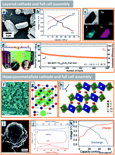 |
| | Fig. 22 Full cell assembly with counterpart cathodes (layered cathodes and hexacyanometallate cathodes). (a) SEM images of P2-K0.41CoO2 and (b) charge and discharge curves of K//P2-K0.41CoO2 cell. Reproduced with permission.158 Copyright 2017, The Royal Society of Chemistry. (c) TEM images and the corresponding EDX mapping of P3-KxCrO2. Reproduced with permission.159 Copyright 2018, The Royal Society of Chemistry. (d) Schematic illustration of a K-ion full cell using a NO-WCT anode and P3-K0.69CrO2 cathode, and (e) the corresponding deep cycling performance. Reproduced with permission.19 Copyright 2019, The Royal Society of Chemistry. (f) SEM image of potassium iron hexacyanoferrate dihydrate particles. Reproduced with permission.161 Copyright 2016, Wiley. (g) Face-centered cubic structure of NiHCF with Prussian blue crystal structure. Reproduced with permission.162 Copyright 2011, American Chemical Society. (h) Structural illustration and (i) morphology of KMHCF powder. Reproduced with permission.163 Copyright 2017, American Chemical Society. (j) Voltage profiles of KMFCN cathode and KTP@C anode, and (k) the corresponding charge/discharge curve of potassium full cell. Reproduced with permission.35 Copyright 2019, Wiley. | |
4.2 Prussian blue analogues (hexacyanometallate) and full cell assembly
As a promising class of cathodes for potassium storage, hexacyanometallate with perovskite-type structure possesses large interstitial sites for alkali metal hosts and fast ion transport, which are induced by the open framework formed by nitrogen-coordinated transition metal cations and carbon-coordinated Fe sites.164,165 For its application in aqueous electrolyte batteries, Qiao et al. synthesized high-potassium-ion-content potassium iron(II) hexacyanoferrate dehydrate nanocubes and investigated their potassium storage potential.161 With the ethylene glycol used as a particle size reducing agent, uniform potassium iron hexacyanoferrate dehydrate nanocubes (K2FeII[FeII(CN)6]·2H2O) with an edge length of 200 nm were obtained (Fig. 22f). The high potassium content ensured their high potential as a potassium-ion reservoir, and further verifies that the open-framework structure could enable structural integrity and fast kinetics. To boost the working durability, Cui et al. developed a low-strain nickel hexacyanoferrate (NiHCF) electrode material with open framework and low voltage hysteresis (8 mV) (Fig. 22g).162 Aiming to increase the working voltage and electrochemical capacity of intercalation cathodes, rationally designed cyanoperovskite KxMnFe(CN)6 (0 ≤ x ≤ 2) was proposed by Goodenough's group.163 After performing inductively coupled plasma (ICP) and thermogravimetric analyses, the initially precipitated products corresponded to K1.89Mn[Fe(CN)6]0.92·0.75H2O (KMHCF) with the Mn–N and Fe–C octahedra occupied by Mn2+ and Fe2+ ions, respectively (Fig. 22h). Notably, when NaCl was adopted to induce optimized secondary particles (Fig. 22i), the charge/discharge stability was enhanced owing to the hindered side reactions and capacity loss at high voltage. Attempting to open a new avenue for low-cost, stable and fast-kinetic potassium full battery, Sun's group for the first time proposed inorganic-open framework anode, namely KTP, and coupled it with activated K1.98Mn[Fe(CN)6]0.92 (KMFCN) cathodes (Fig. 22j).35,163 When it was operated at an average voltage of ca. 3.0 V, the full cell delivered a discharge capacity of 58 mA h g−1 (Fig. 22k), suggesting its potential for more comprehensive investigations. Although Prussian blue analogues demonstrate excellent potassium storage capacity, there are still several disadvantages that need to be addressed, such as interstitial water release and altered stoichiometry.
4.3 Polyanionic compounds and full cell assembly
Combined with safety benefits and tunable redox potentials, polyanionic electrode materials have attracted enormous attention. A unique potassium-based fluorosulfate (KFeSO4F) wrapped by graphene (KFSF@G) was reported by Chen et al. by annealing the precipitate originating from hydrothermally treated graphene, FeSO4, and KF.166 Compared with the ellipsoidal-shaped bare KFSF, KFSF@G exhibited a relatively rough morphology with KFSF modified by cross-linked graphene network (Fig. 23a); the combination of graphene could effectively trigger the enhancement of potassium storage performance from 32.2 mA h g−1 for KFSF to 95.5 mA h g−1 for KFSF@G. In addition, Xu et al. also fabricated polyanionic K3V2(PO4)3 with a 3D conductive carbon network (K3V2(PO4)3/C) using citric acid as both a chelating agent and carbon source.167 After freeze-drying and carbonization, there was a uniform distribution of carbon in K3V2(PO4)3 (Fig. 23b), which could result in enhanced electrolyte penetration and optimized potassium diffusion. Sohn's group also proposed a robust polyanionic compound, KVP2O7.168 Apparently, the as-synthesized KVP2O7 cathode had a particle size of approximately 2 μm and relative concentrations of 24, 26, and 50 at% for K, V, and P (Fig. 23c). To analyze the diffusion and activation energy of K-ions, nudged elastic band calculations were carried out (Fig. 23d). The relatively high activation energy (0.8 eV) compared with those (ca. 0.5 eV) in LIB cathodes was fully surmountable. When tested in potassium half cells, it exhibited an energy density of 253 W h kg−1 at 0.25C, which did not significantly decrease with increased C-rates and prolonged charge/discharge cycles.168 In this study, a unique data-mining protocol was designed, which might pave a new way for the discovery of other functional materials. To enhance the cycling integrity of polyanionic cathodes, Tang et al. proposed a novel iron-based polyanionic cathode (KLi3Fe(C2O4)3@C) for potassium storage. When paired with a soft carbon anode, as illustrated in Fig. 23e, the constructed potassium full cell achieved a remarkable capacity retention of 91% after 200 cycles (Fig. 23f). This indicates a promising prospect as a reliable and stable potassium storage device. Compared with other kinds of cathodes, K-based polyanionic compounds generally have lower specific capacities, which might be ascribed to the bulk nature of the polyanion unit. Based on a study on the intercalation behavior of alkali ions in the olivine phase of A1-xFePO4 (A = alkali metals), potassium ions could be barely inserted into the vacant space in the lattice due to its large radius.171
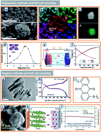 |
| | Fig. 23 Full cell assemble with counterpart cathodes (polyanionic cathodes and organic cathodes). (a) Morphology of bare KFSF (up) and KFSF@G (down). Reproduced with permission.166 Copyright 2020, The Royal Society of Chemistry. (b) The elemental distribution in K3V2(PO4)3/C. Reproduced with permission.167 Copyright 2017, The Royal Society of Chemistry. (c) Morphology of robust KVP2O7 cathode and the corresponding phosphorus distribution, and (d) its activation energy barrier. Reproduced with permission.168 Copyright 2018, Wiley. (e) Schematic working mechanism and (f) its galvanostatic charge and discharge curve of KIB full cell. Reproduced with permission.54 Copyright 2020, The Royal Society of Chemistry. (g) TEM images of PTCDA rod, and (h) charge/discharge profiles of the PTCDA electrode for the 2nd to 5th cycle. Reproduced with permission.169 Copyright 2015, Elsevier. (i) Unit molecular structure and (j) morphology of PAQS. Reproduced with permission.170 Copyright 2016, Elsevier. (k) Schematic diagram of the full cell with graphite anode and PTCDA cathode, and (l) its cycle stability at current density of 30 mA g−1. Reproduced with permission.33 Copyright 2019, Wiley. | |
4.4 Organic cathode and full cell assembly
In recent years, organic electrodes have provided a new avenue for the exploration of potassium cathodes with reasonable cost and optimized recyclability. For instance, Chen's group designed and employed 3,4,9,10-perylene-tetracarboxylicacid-dianhydride (PTCDA) as the cathode in KIBs.169 As illustrated in Fig. 23g, the PTCDA had a large quantity of one-dimensional (1D) rods with a diameter of 200 nm, which could demonstrate a stable cycling capacity of ca. 131 mA h g−1 when tested in a potassium half-cell (Fig. 23h). Poly(anthraquinonyl sulfide) (PAQS) was also evaluated as the cathode material in KIBs.170 As shown in the schematic diagram of PAQS (Fig. 23i), there are two carbonyl groups in one monomer, and the diameter of the PAQS particle is larger than 5 μm (Fig. 23j). Although there was a high reversible capacity of 190 mA h g−1, the cycling stability was still unsatisfactory (75% after 50 cycles), which might be ascribed to the partial dissolution in electrolyte. To further investigate the electrochemical performance of KIB full cells using an organic cathode, Fan et al. assembled the full cell using conventional graphite and PTCDA as the anode and cathode, respectively (Fig. 23k), which provided a stable potassium storage capacity of 80 mA h g−1 at 30 mA g−1 and a high capacity retention of 92.9% after 50 cycles (Fig. 23l). Notably, the detailed potassium storage behavior in organic cathode is not yet well-understood; thus, further investigation is still needed. Corresponding electrochemical results of typical KIB full cells have been organized in Table 5.
Table 5 Comparison of electrochemical performance of typical KIB full cells
|
|
Layered cathode |
Hexacyanometallate cathode |
Polyanionic cathode |
Organic cathode |
| Cathode |
P3-K0.69CrO2 |
K1.98Mn[Fe(CN)6]0.92 |
KLi3Fe(C2O4)3@C |
PTCDA |
| Counterpart anode |
Highly wrinkled carbon tube |
KTiOPO4 |
Soft carbon |
Graphite |
| Voltage range |
0.1–3.6 V |
2.0–4.4 V |
1.5–4.5 V |
1.25–3.5 V |
| Current density |
100 mA g−1 |
20 mA g−1 |
360 mA g−1 |
30 mA g−1 |
| Potassium storage capacity |
52 mA h g−1 |
58 mA h g−1 |
80 mA h g−1 |
80 mA h g−1 |
| Cycling durability |
500 cycles |
Unknown |
200 cycles |
50 cycles |
| Ref. |
19
|
35
|
54
|
33
|
5. Current main challenges
5.1 Electrode integrity
A long cycling performance with remarkable anode durability is a fundamental requirement of battery systems. Nevertheless, owing to the unstable electrode structure, continuous electrolyte consumption, and volume change during repeated cycling, it is difficult to maintain the stability of KIBs.172–174 In 2019, Glushenkov et al. systematically analyzed the abrupt capacity decay in an antimony–carbon nanocomposite-based potassium anode, and found that mechanical degradation was the primary reason for capacity drop.8 Owing to the repeated expansion-contraction of the electrode, large cracks appeared on the electrode surface, and a significant amount of active materials detached from the current collector (Fig. 24a). Thus, the volume change during cycling could remarkably destroy the integrity of the electrode, which was evident by the visible electrode residue on the extracted separator. Additionally, Younesi and coworkers also reported severe capacity decay in milled graphite anodes, as shown in Fig. 24b.23 Although the anodes exhibited a high initial potassiation capability of 345 mA h g−1, an obvious capacity jump was observed within 20 cycles, and the coulombic efficiency underwent severe fluctuations after 100 cycles, making it impossible to fabricate a reliable practical full cell.
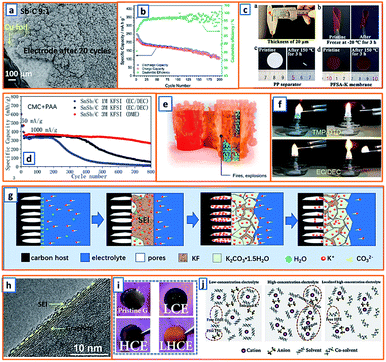 |
| | Fig. 24 Current main challenges in KIB application. (a) SEM images of the unstable Sb–C electrode. Reproduced with permission.8 Copyright 2019, Elsevier. (b) Unstable cycling performance of the ball-milled graphite electrode. Reproduced with permission.23 Copyright 2019, The Royal Society of Chemistry. (c) Performance of PFSA-K membrane and pristine separator at −20 °C and 150 °C. Reproduced with permission.49 Copyright 2020, Elsevier. (d) Cycling performance of SnSb/C with CMC + PAA binder and various electrolytes. Reproduced with permission.71 Copyright 2020, Elsevier. (e) Battery combustion image. Reproduced with permission.79 Copyright 2020, Elsevier. (f) Flammability test for TMP and EC-DEC based electrolyte. Reproduced with permission.98 Copyright 2020, Wiley. (g) Schematic illustration of SEI phase change during the charge/discharge process of BPCS anode. Reproduced with permission.113 Copyright 2020, American Chemical Society. (h) TEM images of the interface layer between graphite and DEGDME after 20 cycles. Reproduced with permission.121 Copyright 2019, Elsevier. (i) Optical images of the pristine graphite and potassiated graphite with LCE, HCE, and LHCE, and (j) schematic illustrations of solution structures of LCE, HCE, and LHCE. Reproduced with permission.126 Copyright 2019, Wiley. | |
5.2 Temperature durability
Typically, temperature can significantly influence the performance of energy storage devices; gassing and rapid consumption of organic additives can be induced at increased temperatures, leading to the formation of resistive SEI layer with high impedance. On the other hand, a low operating temperature could inevitably suppress the ionic conductivity in battery systems. In order to enhance the thermal durability and long-term stability, Xu's group proposed a facile strategy for the fabrication of potassium-ion composite electrolyte membranes, which exhibited favorable ionic conductivity over a wide temperature range from −15 to 85 °C.49 Perfluorinated sulfonic resin powder (PFSA-K) was dissolved in DMF and then mixed with a traditional liquid electrolyte in K-ion battery (1 M KFP6 in EC/DEC with equal volume ratio). After forming homogeneous solution upon continuous stirring, the designed PFSA-K could be prepared by blade coating and drying, and had a thickness of 20 μm; satisfactory mechanical flexibility was obtained with no observed fragility or cracking after freezing and folding tests (Fig. 24c). Moreover, compared with the shrunk pristine separator, the PFSA-K maintained its original size without obvious changes, indicating its excellent tolerance to high temperatures. With high ionic conductivity (9.31 × 10⁻⁵ S cm−1), the PFSA-K was applied in K-ion battery and provided a desirable reversible capacity of 99.7 mA h g−1 at −20 °C for half-cell and 90.7 mA h g−1 at −15 °C for full cells.49 Thus, the thermal durability is of high importance for the fulfillment of good potassium storage performance which requires significant attention in the near future.
5.3 Component compatibility
Because of electrolyte decomposition and/or graphite exfoliation during K+-solvent co-insertion, the incompatibility of electrolyte and graphite always results in failure of potassium storage, which should not be ignored.175 Guo et al. checked the stability of potassium anodes and focused on the engineered compatibility of different components of KIBs. With the condensation reaction between the hydroxyl groups of CMC and the carboxylic acid moieties of PAA, the compatible CMC/PAA binder exhibited higher viscoelasticity and mechanical strength and was applied in the designed anode to accommodate the volume change during potassium insertion, which illustrated an improved potassium storage performance of 340 mA h g−1 with 80.7% capacity retention for 800 cycles at 1000 mA g−1 (Fig. 24d).71 It indicated the successful formation of stable SEI layers and the suppression of electrolyte decomposition. Although there is already remarkable improvement in the cycling integrity and stability of KIB, the capacity decay as a result of component incompatibility was not thoroughly mitigated, and the degeneration of electrode structure is still needed to be further addressed.
5.4 Battery safety
Safety remains a critical factor in determining the practical applications of large-scale rechargeable batteries. Electrolytes in potassium ion batteries are generally composed of cyclic and linear alkyl carbonates, which are highly volatile and intrinsically flammable. For example, the conventional carbonate electrolyte (EC/DMC with a weight ratio of 1:1) has a vapor pressure of 4.8 kPa at room temperature and an extremely low flash point of 25 ± 1 °C at an air pressure of 1.013 bar, which makes it prone to catch fire and cause explosions (Fig. 24e).79 Furthermore, potassium metal possesses extremely high activity. Therefore, the risk of ignition is actually very high and more attention during the KIB research should be paid to ensure safety during research on KIBs. Liu and his coworkers investigated the flammability of electrolytes by comparing conventional electrolytes and modified electrolytes with trimethyl phosphate (TMP) and ethylene sulfate as non-flammable solvent and functional additive, respectively.98 As shown in Fig. 24f, compared with the traditional EC/DEC-based electrolyte, the TMP-based electrolyte with low viscosity (1.3 vs. 2.5 mPa s of propylene carbonate), wide operating temperature range (−46 to 197 °C), and high flash point (148 °C) was non-flammable and difficult to be ignited.98,176,177 Moreover, Mao et al. also proposed triethyl phosphate (TEP) as the sole solvent of potassium electrolyte due to its fire-retardant property.178 Owing to the weak solvation of potassium cations by TEP, the electrolyte demonstrated low viscosity as well as high conductivity. Therefore, electrolytes in KIBs play an important role in the safety of the battery systems, and through rational component design, nonflammable electrolytes can be achieved. However, other safety issues, such as gas release from cathode compounds and potassium dendrite growth, have not been adequately investigated.
5.5 Interface protection
Interface protection plays an important role in enhancing the stability of electrode structure and cycling durability. Generally, an unprotected electrode usually leads to severe K-ion loss and thick SEI formation, resulting in a high “dead” cathode ratio after the first cycle and limiting the performance of a practical full cell. With the aim of designing a reliable interface, Feng and coworkers investigated the interface stability of carbon sheet and created a K2CO3·1.5H2O-dominated SEI through interfacial transfer of carbonate groups.113 In the early stage of potassiation, the K ions reacted with the grafted carbonate groups on carbon surface and the trace water in the electrolytes to form K2CO3·1.5H2O grains. Subsequently, the charge-transfer resistance would be increased by the dense SEI structure. During the depotassiation process, slight rearrangement of K2CO3·1.5H2O grains occurred, creating abundant ion-transfer pathways (Fig. 24g). Thus, a dense and stable interfacial film with numerous ion-transfer pathways was successfully constructed. This research demonstrates the importance of interface strength and proposes a potential way for protection. To gain a deeper understanding of the interfacial strength, typical K/graphite was employed to investigate the effect of SEI on the capacity fading behavior in ester- (EC/DEC) and ether- (DEGDME) based electrolytes.121 Compared with the amorphous SEI layer with a thickness of 4 nm on graphite in EC/DEC, a smooth and thinner SEI layer of 0.5–1.5 nm was obtained in DEGDME (Fig. 24h), which could effectively stabilize the microcrystalline structure of the graphite anode without drastic distortion. In addition, utilizing electrolytes with high concentrations instead of the conventional low-concentrated electrolytes is an effective way to avoid the formation of fragile interfacial layer. By adding highly fluorinated ether (HFE) into concentrated potassium bis(fluorosulfonyl)imide/dimethoxyethane (KFSI/DME), Wu et al. prepared a localized high-concentration electrolyte (LHCE), which guaranteed sufficient potassium intercalation in the graphite anode, displaying a typical bronze color consisting of the major KC8 and minor KC24 (Fig. 24i).126 With the addition of a low-polarity cosolvent, HFE, in HCE, the reinforced 3D network was broken (Fig. 24j), leading to local coordination in LHCE and optimized wettability.126 Besides, the low solubility of KF in HFE and DME further improved the stability of the KF-rich interface, whereas the conventional unstable KF-lean layer could not sustain long-term insertion/extraction of potassium ions. This work provides a better understanding of the importance of interface protection and its influence on potassium storage performance.
5.6 Areal capacity
For practical energy storage devices, the areal capacity should be sufficiently high to maintain sufficient potassium storage capability. Typically, while preparing anodes with low mass loadings, the corresponding areal capacity is ignored. Currently, the energy density of potassium batteries is still at a low level and far from that required for practical applications. For example, WS2 anode was recently investigated by Wu and coworkers which illustrated an areal capacity of approximately 0.1 mA h cm−2.179 Novel FeSe2/nitrogen-doped carbon composite fabricated by Liu et al. had a low areal capacity of 0.4 mA h cm−2.180 Bismuth oxyhalide was applied by Yong et al. as an anode in KIBs, which exhibited an areal capacity of approximately 0.55 mA h cm−2.114 With a specially designed electrolyte, Ming et al. improved the areal capacity of graphite anode from 0.2 to 0.5 mA h cm−2.181 At this stage, the areal capacity is far from that of conventional LIBs, and unique material engineering and rational electrode design are still required.
6. Conclusion and perspective
Potassium-ion-based rechargeable batteries are emerging technologies that can compete with LIBs and SIBs owing to notable merits such as low cost, resource abundance, feasibility of light aluminum as substrates, and high working voltage. Apparently, the widely studied LIB technology has provided an appropriate technical background for the exploration of KIBs and is expected to facilitate the rapid development of KIBs. Based on the successful application of LIB technology, KIBs also have the potential to be cost-effective and practically utilized. Nevertheless, the intrinsic differences between lithium and potassium could not be neglected during the development of KIBs. It should also be noted that KIBs are not certainly the replacement of lithium storage devices, which exhibit certain unique features. Furthermore because of the limited volume for battery packs in portable devices and electric hybrid vehicles, KIBs with undesirable gravimetric/volumetric energy densities seem to be only suitable for stationary applications, as the cost of stationary energy system is much more critical than the weight or size. To further expand its future application, the exploration of high-performing electrode active materials is essential. As anode active materials in KIBs have relatively well-understood potassium storage processes, which are similar to those in LIBs, more attention has been paid to the development of anodes during the past several years, and various anode candidates have been reported. Therefore, a review of recently developed advanced anode materials for rechargeable potassium batteries is essential for gaining an insight into the associated scientific and practical issues. This could further shed light on ways to improve existing potassium storage systems. In this review, state-of-the-art progress of the anodes of potassium ion batteries was summarized and growing trends in its synthesis, chemistry, and applications were proposed.
(1) The synthesis strategies, i.e., hydrothermal treatment, mechanical milling, chemical etching, facile annealing, co-precipitation, electrospinning, spray drying, electrodeposition, and CVD, were discussed; potassium storage behaviors and the application of corresponding composites, including alloying-type anodes, conversion-type anodes, intercalation-type compounds, anodes with multiple potassium storage behaviors, organic anodes, and carbonaceous anodes, were also systematically summarized. In particular, the anodes with multiple potassium storage behaviors were classified into three groups: conversion–alloy anodes, conversion–decomposition anodes, and intercalation–conversion anodes.
(2) Graphite is an attractive anode material for rechargeable potassium batteries owing to its reasonable working potential and relatively reliable stability. Compared with graphite, non-graphite carbonaceous materials exhibit higher potassium storage performance. However, there are still challenges in the exploration of stable microstructures and compatible electrolytes. Intercalation-type titanium-based compounds have attracted significant attention owing to their excellent cycling stability and remarkable safety induced by their high intercalation potential. Nevertheless, their unsatisfactory energy density has diverted some researchers to explore conversion-type active materials with high theoretical specific capacities. Although the alloying-type anode also has satisfactory specific capacity upon sufficient potassiation at low operating potentials, the corresponding structural constraints should not be ignored. During repeated charge/discharge, there is always a severe volume variation and significant particle aggregation, which generally results in the loss of electrical contact and rapid capacity fading. Apart from structural engineering and effective modification by carbon and other inert buffers, more efforts should be made to optimize the electrode integrity and guarantee reliable cycling.
(3) Although a series of advanced anodes have been developed, other potential candidates are still needed to be explored in detail. For instance, environmentally friendly silicon electrodes that maintain impressive electrochemical activity at low potentials with respect to lithium metal (4200 mA h g−1 for Li22Si5 and 3579 mA h g−1 for Li15Si4) are one of the most promising anode candidates for LIBs; according to previous theoretical research, a silicon-based anode could also provide a significantly high potassium storage capability of 955 mA h g−1 through the formation of KSi alloy.182,183 Glushenkov et al. attempted to fabricate a silicon-based anode for potassium storage by dispersing silicon nanoparticles in a graphene matrix with a weight ratio of 1:1. Nonetheless, no typical alloying–dealloying process was identified in the charge/discharge profiles, and a low capacity was measured from pure Si electrodes in potassium cells, indicating that silicon made negligible contribution to potassium storage. In addition, the minor electrochemical activity was likely capacitive in nature as various engineered nanosilicon materials can act as supercapacitor electrode materials.184–186 Therefore, to further expand the application of silicon-based anodes with high theoretical capacity in KIBs, it is crucial to find an ingenious way to break through the inert nature of silicon in the near future by conducting in-depth studies.
(4) Theoretical calculations are effective and imperative for the exploitation of suitable KIB anode materials. Through density functional theory (DFT) calculations, Wang et al. found that there was a high diffusion barrier of K+ ions (1.82 eV) in bulk Ta2NiSe5, which could be decreased to 0.85 eV when the interlayer was expanded by liquid exfoliation.187 Thus, a few-layered ternary Ta2NiSe5 with an interlayer spacing of up to 1.1 nm was proposed, which provided high potassium storage capacity and excellent rate capability. Additionally, Zhang and coworkers further applied DFT calculations to phase structure identification, and successfully computed the phase diagram of the potassiation process of bismuth anode.66 Thus, to some extent, DFT calculations could effectively set a direction for active material exploration and provide valuable structural information during the battery working process.
(5) Generally, increasing the mass loading of the electrode and the tap density of active materials is essential for the promotion of areal capacity and optimization of the energy storage capacity of the fabricated battery. However, the random, close packing of electrode components typically results in a tortuous pore structure in the electrode, significantly increasing the ion transfer distance and impeding the infiltration of the electrolyte. To promote ion permeability and transfer rate, the development of novel anode architecture with low tortuosity is a feasible approach. Previous attempts have verified that direction-ordered pore structures can decrease the diffusion distance and enable the fabrication of thick electrodes. For instance, a vertically aligned anode could be prepared by using titanium carbide (Ti3C2Tx) as the model material.188 Owing to the optimized ion transfer kinetics, the resulting anode reached a thickness of up to 200 μm. In addition, the chain assembly of magnetic emulsion droplets along the magnetic field direction could also achieve a high-loading (310 μm) anode with an impressive areal capacity of over 12 mA h cm−2.189 Recently, 3D printing techniques have emerged as a facile way to prepare anodes with high loading and fast ion diffusion through rational structure design. However, due to its less scalable nature, this unique technique can only be applied in lab-scale investigations and further studies are required to develop it.
Therefore, advanced anodes with good electrode strength, low cost, facile preparation, and satisfactory potassium storage capability are vital for the fabrication of reliable KIBs and meeting the ever-increasing energy demand. Although remarkable enhancements have been realized in the past few years, significant challenges remain and further research is required. We believe that this summary of state-of-the-art progress in anodes of potassium ion batteries will strengthen our present understanding of rechargeable potassium-battery systems, and advanced KIBs with satisfactory energy storage performance could certainly be achieved through purposeful and thorough investigation by researchers worldwide.
Author contributions
P. Li and Y.-K. Sun conceived and designed the structure of the review. P. Li and H.-G. Jung collected the papers related to the topic of the review. P. Li and Y.-K. Sun wrote the manuscript. Y.-K. Sun finished the language polishing. All the authors commented on and revised the manuscript.
Conflicts of interest
There are no conflicts to declare.
Acknowledgements
This work was supported by the Global Frontier R&D Program (2013M3A6B1078875) of the Center for Hybrid Interface Materials (HIM) funded by the Ministry of Science; National Research Foundation of Korea (NRF) grant funded by the Korea government Ministry of Education and Science Technology (MEST) (NRF-2018R1A2B3008794).
Notes and references
- J. Ding, H. L. Zhang, H. Zhou, J. Feng, X. R. Zheng, C. Zhong, E. S. Paek, W. B. Hu and D. Mitlin, Adv. Mater., 2019, 31, 1900429 CrossRef.
- D. Liu, L. Yang, Z. Chen, G. Zou, H. Hou, J. Hu and X. Ji, Sci. Bull., 2020, 65, 1003–1012 CrossRef CAS.
- G. Suo, D. Li, L. Feng, X. Hou, Y. Yang and W. A. Wang, J. Electroanal. Chem., 2019, 833, 113–118 CrossRef CAS.
- X. Zhao, W. Wang, Z. Hou, G. Wei, Y. Yu, J. Zhang and Z. Quan, Chem. Eng. J., 2019, 370, 677–683 CrossRef CAS.
- L. Fang, J. Xu, S. Sun, B. Lin, Q. Guo, D. Luo and H. Xia, Small, 2019, 15, 1804806 CrossRef.
- G. Ma, K. Huang, J.-S. Ma, Z. Ju, Z. Xing and Q. C. Zhuang, J. Mater. Chem. A, 2017, 5, 7854–7861 RSC.
- Y. Tian, Y. An, S. Xiong, J. Feng and Y. Qian, J. Mater. Chem. A, 2019, 7, 9716–9725 RSC.
- I. Sultana, M. M. Rahman, J. Liu, N. Sharma, A. V. Ellis, Y. Chen and A. M. Glushenkov, J. Power Sources, 2019, 413, 476–484 CrossRef CAS.
- P. Lian, Y. Dong, Z.-S. Wu, S. Zheng, X. Wang, S. Wang, C. Sun, J. Qin, X. Shi and X. Bao, Nano Energy, 2017, 40, 1–8 CrossRef CAS.
- X. Xiang, D. Liu, X. Zhu, K. Fang, K. Zhou, H. Tang, Z. Xie, J. Li, H. Zheng and D. Qu, Appl. Surf. Sci., 2020, 145947 CrossRef CAS.
- Y. Dong, Z.-S. Wu, S. Zheng, X. Wang, J. Qin, S. Wang, X. Shi and X. Bao, ACS Nano, 2017, 11, 4792–4800 CrossRef.
- Y. Liang, C. Luo, F. Wang, S. Hou, S. C. Liou, T. Qing, Q. Li, J. Zheng, C. Cui and C. Wang, Adv. Energy Mater., 2019, 9, 1802986 CrossRef.
- K. Huang, Z. Xing, L. Wang, X. Wu, W. Zhao, X. Qi, H. Wang and Z. Ju, J. Mater. Chem. A, 2018, 6, 434–442 RSC.
- I. Sultana, M. M. Rahman, S. Mateti, V. G. Ahmadabadi, A. M. Glushenkov and Y. Chen, Nanoscale, 2017, 9, 3646–3654 RSC.
- J. Li, B. Rui, W. Wei, P. Nie, L. Chang, Z. Le, M. Liu, H. Wang, L. Wang and X. Zhang, J. Power Sources, 2020, 449, 227481 CrossRef CAS.
- H. Qiu, L. Zhao, M. Asif, X. Huang, T. Tang, W. Li, T. Zhang, T. Shen and Y. Hou, Energy Environ. Sci., 2020, 13, 571–578 RSC.
- J. Liu, T. Yin, B. Tian, B. Zhang, C. Qian, Z. Wang, L. Zhang, P. Liang, Z. Chen and J. Yan, Adv. Energy Mater., 2019, 9, 1900579 CrossRef.
- W. Li, B. Yan, H. Fan, C. Zhang, H. Xu, X. Cheng, Z. Li, G. Jia, S. An and X. Qiu, ACS Appl. Mater. Interfaces, 2019, 11, 22364–22370 CrossRef CAS.
- P. Li, J. Y. Hwang and Y. K. Sun, J. Mater. Chem. A, 2019, 7, 20675–20682 RSC.
- H. Lin, M. Li, X. Yang, D. Yu, Y. Zeng, C. Wang, G. Chen and F. Du, Adv. Energy Mater., 2019, 9, 1900323 CrossRef.
- X. Zhou, L. Chen, W. Zhang, J. Wang, Z. Liu, S. Zeng, R. Xu, Y. Wu, S. Ye and Y. Feng, Nano Lett., 2019, 19, 4965–4973 CrossRef CAS PubMed.
- G. Wang, X. Xiong, D. Xie, Z. Lin, J. Zheng, F. Zheng, Y. Li, Y. Liu, C. Yang and M. Liu, J. Mater. Chem. A, 2018, 6, 24317–24323 RSC.
- M. Carboni, A. J. Naylor, M. Valvo and R. Younesi, RSC Adv., 2019, 9, 21070–21074 RSC.
- L. Chen, S. Liu, Y. Wang, W. Liu, Y. Dong, Q. Kuang and Y. Zhao, Electrochim. Acta, 2019, 294, 46–52 CrossRef CAS.
- B. Kishore, G. Venkatesh and N. Munichandraiah, J. Electrochem. Soc., 2016, 163, A2551 CrossRef CAS.
- K. Lei, C. Wang, L. Liu, Y. Luo, C. Mu, F. Li and J. Chen, Angew. Chem., Int. Ed., 2018, 130, 4777–4781 CrossRef.
- X. Li, N. Sun, X. Tian, T. Yang, Y. Song, B. Xu and Z. Liu, Energy Fuels, 2020, 34, 2445–2451 CrossRef CAS.
- Q. Yang, Z. Wang, W. Xi and G. He, Electrochem. Commun., 2019, 101, 68–72 CrossRef CAS.
- C. Wang, W. Tang, Z. Yao, B. Cao and C. Fan, Chem. Commun., 2019, 55, 1801–1804 RSC.
- Y. Qian, S. Jiang, Y. Li, Z. Yi, J. Zhou, J. Tian, N. Lin and Y. Qian, Angew. Chem., Int. Ed., 2019, 131, 18276–18283 CrossRef.
- C. Zeng, F. Xie, X. Yang, M. Jaroniec, L. Zhang and S. Z. Qiao, Angew. Chem., Int. Ed., 2018, 130, 8676–8680 CrossRef.
- Y. Han, T. Li, Y. Li, J. Tian, Z. Yi, N. Lin and Y. Qian, Energy Storage Mater., 2019, 20, 46–54 CrossRef.
- L. Fan, R. Ma, Q. Zhang, X. Jia and B. Lu, Angew. Chem., Int. Ed., 2019, 58, 10500–10505 CrossRef CAS.
- X. Wu, W. Zhao, H. Wang, X. Qi, Z. Xing, Q. Zhuang and Z. Ju, J. Power Sources, 2018, 378, 460–467 CrossRef CAS.
- R. Zhang, J. Huang, W. Deng, J. Bao, Y. Pan, S. Huang and C. F. Sun, Angew. Chem., Int. Ed., 2019, 58, 16474–16479 CrossRef CAS.
- H. Wang, Z. Xing, Z. Hu, Y. Zhang, Y. Hu, Y. Sun, Z. Ju and Q. Zhuang, Appl. Mater. Today, 2019, 15, 58–66 CrossRef.
- H. Gao, T. Zhou, Y. Zheng, Q. Zhang, Y. Liu, J. Chen, H. Liu and Z. Guo, Adv. Funct. Mater., 2017, 27, 1702634 CrossRef.
- V. Lakshmi, Y. Chen, A. A. Mikhaylov, A. G. Medvedev, I. Sultana, M. M. Rahman, O. Lev, P. V. Prikhodchenko and A. M. Glushenkov, Chem. Commun., 2017, 53, 8272–8275 RSC.
- Z. Liu, J. Wang, X. Jia, W. Li, Q. Zhang, L. Fan, H. Ding, H. Yang, X. Yu and X. Li, ACS Nano, 2019, 13, 10631–10642 CrossRef CAS PubMed.
- L. Li, W. Zhang, X. Wang, S. Zhang, Y. Liu, M. Li, G. Zhu, Y. Zheng, Q. Zhang and T. Zhou, ACS Nano, 2019, 13, 7939–7948 CrossRef CAS PubMed.
- Z. Wang, K. Dong, D. Wang, S. Luo, Y. Liu, Q. Wang, Y. Zhang, A. Hao, C. Shi and N. Zhao, J. Power Sources, 2019, 441, 227191 CrossRef CAS.
- D. Li, X. Ren, Q. Ai, Q. Sun, L. Zhu, Y. Liu, Z. Liang, R. Peng, P. Si and J. Lou, Adv. Energy Mater., 2018, 8, 1802386 CrossRef.
- S. Tian, Q. Jiang, T. Cai, Y. Wang, D. Wang, D. Kong, H. Ren, J. Zhou and W. Xing, J. Power Sources, 2020, 474, 228479 CrossRef CAS.
- H. Huang, J. Cui, G. Liu, R. Bi and L. Zhang, ACS Nano, 2019, 13, 3448–3456 CrossRef CAS PubMed.
- Y. Xie, Y. Dall'Agnese, M. Naguib, Y. Gogotsi, M. W. Barsoum, H. L. Zhuang and P. R. Kent, ACS Nano, 2014, 8, 9606–9615 CrossRef CAS PubMed.
- L. Gao, Z. Wang, H. Hu, H. Cheng, L. Zhang and X. Yang, J. Electroanal. Chem., 2020, 876, 114483 CrossRef CAS.
- H. Wang, X. Wu, X. Qi, W. Zhao and Z. Ju, Mater. Res. Bull., 2018, 103, 32–37 CrossRef.
- C. Liu, S. Luo, H. Huang, Y. Zhai and Z. Wang, ChemSusChem, 2019, 12, 873–880 CrossRef CAS.
- G. Du, M. Tao, D. Liu, M. K. Aslam, Y. Qi, J. Jiang, Y. Li, S.-j. Bao and M. Xu, J. Colloid Interface Sci., 2020, 582, 932–939 CrossRef.
- J. Chu, Q. Yu, D. Yang, L. Xing, C.-Y. Lao, M. Wang, K. Han, Z. Liu, L. Zhang and W. Du, Appl. Mater. Today, 2018, 13, 344–351 CrossRef.
- H. He, W. Yao, S. Tunmee, X. Zhou, B. Ji, N. Wu, T. Song, P. Kidkhunthod and Y. Tang, J. Mater. Chem. A, 2020, 8, 9128–9136 RSC.
- Q. Deng, J. Pei, C. Fan, J. Ma, B. Cao, C. Li, Y. Jin, L. Wang and J. Li, Nano Energy, 2017, 33, 350–355 CrossRef CAS.
- W. Zhang, J. Mao, S. Li, Z. Chen and Z. Guo, J. Am. Chem. Soc., 2017, 139, 3316–3319 CrossRef CAS PubMed.
- I. Sultana, T. Ramireddy, M. M. Rahman, Y. Chen and A. M. Glushenkov, Chem. Commun., 2016, 52, 9279–9282 RSC.
- Y. Xu, C. Zhang, M. Zhou, Q. Fu, C. Zhao, M. Wu and Y. Lei, Nat. Commun., 2018, 9, 1–11 CrossRef.
- Y.-K. Sun, S.-T. Myung, B.-C. Park, J. Prakash, I. Belharouak and K. Amine, Nat. Mater., 2009, 8, 320–324 CrossRef CAS.
- B. Dunn, H. Kamath and J.-M. Tarascon, Science, 2011, 334, 928–935 CrossRef CAS.
- L. Wang, J. Yang, J. Li, T. Chen, S. Chen, Z. Wu, J. Qiu, B. Wang, P. Gao and X. Niu, J. Power Sources, 2019, 409, 24–30 CrossRef CAS.
- M. Shimizu, R. Yatsuzuka, T. Koya, T. Yamakami and S. Arai, ACS Appl. Energy Mater., 2018, 1, 6865–6870 CrossRef CAS.
- K. Cao, S. Wang, Y. Jia, D. Xu, H. Liu, K.-J. Huang, Q.-S. Jing and L. Jiao, Chem. Eng. J., 2020, 126902 Search PubMed.
- Y. Zhao, J. Zhu, S. J. H. Ong, Q. Yao, X. Shi, K. Hou, Z. J. Xu and L. Guan, Adv. Energy Mater., 2018, 8, 1802565 CrossRef.
- I. Sultana, M. M. Rahman, T. Ramireddy, Y. Chen and A. M. Glushenkov, J. Mater. Chem. A, 2017, 5, 23506–23512 RSC.
- S. Ding, B.-X. Zhou, C. Chen, Z. Huang, P. Li, S. Wang, G. Cao and M. Zhang, ACS Nano, 2020, 14, 9626–9636 CrossRef CAS.
- S. Yang, G. D. Park and Y. C. Kang, Appl. Surf. Sci., 2020, 529, 147140 CrossRef CAS.
- R. Hao, H. Lan, C. Kuang, H. Wang and L. Guo, Carbon, 2018, 128, 224–230 CrossRef CAS.
- J. Huang, X. Lin, H. Tan and B. Zhang, Adv. Energy Mater., 2018, 8, 1703496 CrossRef.
- J. Han, M. Xu, Y. Niu, G.-N. Li, M. Wang, Y. Zhang, M. Jia and C. ming Li, Chem. Commun., 2016, 52, 11274–11276 RSC.
- Z. Sang, D. Su, J. Wang, Y. Liu and H. Ji, Chem. Eng. J., 2020, 381, 122677 CrossRef CAS.
- Y. N. Ko, S. H. Choi, H. Kim and H. J. Kim, ACS Appl. Mater. Interfaces, 2019, 11, 27973–27981 CrossRef CAS PubMed.
- N. Cheng, J. Zhao, L. Fan, Z. Liu, S. Chen, H. Ding, X. Yu, Z. Liu and B. Lu, Chem. Commun., 2019, 55, 12511–12514 RSC.
- J. Wu, Q. Zhang, S. Liu, J. Long, Z. Wu, W. Zhang, W. K. Pang, V. Sencadas, R. Song and W. Song, Nano Energy, 2020, 77, 105118 CrossRef CAS.
- C. Fan, M. Zhao, C. Li, C. Wang, B. Cao, X. Chen, Y. Li and J. Li, Electrochim. Acta, 2017, 253, 333–338 CrossRef CAS.
- Y. Lu and J. Chen, Sci. China: Chem., 2017, 60, 1533–1539 CrossRef CAS.
- Z. Huang, Z. Chen, S. Ding, C. Chen and M. Zhang, Mater. Lett., 2018, 219, 19–22 CrossRef CAS.
- Q. Peng, S. Zhang, H. Yang, B. Sheng, R. Xu, Q. Wang and Y. Yu, ACS Nano, 2020, 14, 6024–6033 CrossRef CAS.
- Q. Xu, Q. Li, Y. Guo, D. Luo, J. Qian, X. Li and Y. Wang, Small Methods, 2020, 4, 2000159 CrossRef CAS.
- Q. Yao, J. Zhang, X. Shi, B. Deng, K. Hou, Y. Zhao and L. Guan, Electrochim. Acta, 2019, 307, 118–128 CrossRef CAS.
- C. Han, K. Han, X. Wang, C. Wang, Q. Li, J. Meng, X. Xu, Q. He, W. Luo and L. Wu, Nanoscale, 2018, 10, 6820–6826 RSC.
- K. Liu, Y. Liu, D. Lin, A. Pei and Y. Cui, Sci. Adv., 2018, 4, eaas9820 CrossRef.
- J. Han, Y. Niu, S.-j. Bao, Y.-N. Yu, S.-Y. Lu and M. Xu, Chem. Commun., 2016, 52, 11661–11664 RSC.
- J. Qin, H. M. K. Sari, C. He and X. Li, J. Mater. Chem. A, 2019, 7, 3673–3681 RSC.
- J. Chu, W. A. Wang, Q. Yu, C.-Y. Lao, L. Zhang, K. Xi, K. Han, L. Xing, L. Song and M. Wang, J. Mater. Chem. A, 2020, 8, 779–788 RSC.
- Q. Liu, L. Fan, S. Chen, S. Su, R. Ma, X. Han and B. Lu, Energy Technol., 2019, 7, 1900634 CrossRef CAS.
- C. Yan, X. Gu, L. Zhang, Y. Wang, L. Yan, D. Liu, L. Li, P. Dai and X. Zhao, J. Mater. Chem. A, 2018, 6, 17371–17377 RSC.
- W. Zhang, J. Ming, W. Zhao, X. Dong, M. N. Hedhili, P. M. Costa and H. N. Alshareef, Adv. Funct. Mater., 2019, 29, 1903641 CrossRef.
- K. Chayambuka, G. Mulder, D. L. Danilov and P. H. Notten, Adv. Energy Mater., 2018, 8, 1800079 CrossRef.
- C.-J. Yang and R. B. Jackson, Renewable Sustainable Energy Rev., 2011, 15, 839–844 CrossRef.
- Y. Bai, W. Fu, W. Chen, Z. Chen, X. Pan, X. Lv, J. Wu and X. Pan, J. Mater. Chem. A, 2019, 7, 24454–24461 RSC.
- Y. Zhang, M. Li, F. Huang, Y. Li, Y. Xu, F. Wang, Q. Yao, H. Zhou and J. Deng, Appl. Surf. Sci., 2020, 499, 143907 CrossRef CAS.
- D.-S. Bin, S.-Y. Duan, X.-J. Lin, L. Liu, Y. Liu, Y.-S. Xu, Y.-G. Sun, X.-S. Tao, A.-M. Cao and L.-J. Wan, Nano Energy, 2019, 60, 912–918 CrossRef CAS.
- J. Wang, B. Wang, X. Liu, J. Bai, H. Wang and G. Wang, Chem. Eng. J., 2020, 382, 123050 CrossRef CAS.
- P. Li, J.-Y. Hwang, S.-M. Park and Y.-K. Sun, J. Mater. Chem. A, 2018, 6, 12551–12558 RSC.
- V. Lakshmi, A. A. Mikhaylov, A. G. Medvedev, C. Zhang, T. Ramireddy, M. M. Rahman, P. Cizek, D. Golberg, Y. Chen and O. Lev, J. Mater. Chem. A, 2020, 8, 11424–11434 RSC.
- J. Ge, L. Fan, J. Wang, Q. Zhang, Z. Liu, E. Zhang, Q. Liu, X. Yu and B. Lu, Adv. Energy Mater., 2018, 8, 1801477 CrossRef.
- W. C. Chang, J. H. Wu, K. T. Chen and H. Y. Tuan, Adv. Sci., 2019, 6, 1801354 CrossRef.
- H. Tan, X. Du, J.-Q. Huang and B. Zhang, Chem. Commun., 2019, 55, 11311–11314 RSC.
- X. Cheng, D. Li, Y. Wu, R. Xu and Y. Yu, J. Mater. Chem. A, 2019, 7, 4913–4921 RSC.
- G. Liu, Z. Cao, L. Zhou, J. Zhang, Q. Sun, J. Y. Hwang, L. Cavallo, L. Wang, Y. K. Sun and J. Ming, Adv. Funct. Mater., 2020, 30, 2001934 CrossRef CAS.
- B. Lee, M. Kim, S. Kim, J. Nanda, S. J. Kwon, H. D. Jang, D. Mitlin and S. W. Lee, Adv. Energy Mater., 2020, 10, 1903280 CrossRef CAS.
- W. Xiong, J. Zhang, Y. Xiao, Y. Zhu, Z. Wang and Z. Lu, Chem. Commun., 2020, 56, 3433–3436 RSC.
- J. Zheng, Y. Yang, X. Fan, G. Ji, X. Ji, H. Wang, S. Hou, M. R. Zachariah and C. Wang, Energy Environ. Sci., 2019, 12, 615–623 RSC.
- J. Wu, X. Zhang, Z. Li, C. Yang, W. Zhong, W. Li, C. Zhang, N. Yang, Q. Zhang and X. Li, Adv. Funct. Mater., 2020, 2004348 CrossRef CAS.
- J. Liao, Q. Hu, J. Mu, X. He, S. Wang, D. Jiemin and C. Chen, Chem. Commun., 2019, 55, 13916–13919 RSC.
- D. Li, Q. Sun, Y. Zhang, L. Chen, Z. Wang, Z. Liang, P. Si and L. Ci, ChemSusChem, 2019, 12, 2689–2700 CrossRef CAS PubMed.
- D. Li, Y. Zhang, Q. Sun, S. Zhang, Z. Wang, Z. Liang, P. Si and L. Ci, Energy Storage Mater., 2019, 23, 367–374 CrossRef.
- Y. Gao, Q. Ru, Y. Liu, S. Cheng, L. Wei, F. C. C. Ling, F. Chen and X. Hou, ChemElectroChem, 2019, 6, 4689–4695 CrossRef CAS.
- P. Li, J.-Y. Hwang and Y.-K. Sun, ACS Nano, 2019, 13, 2624–2633 CAS.
- W.-J. Kwak, Rosy, D. Sharon, C. Xia, H. Kim, L. R. Johnson, P. G. Bruce, L. F. Nazar, Y.-K. Sun and A. A. Frimer, Chem. Rev., 2020, 120, 6626–6683 CrossRef CAS.
- Y. Li, C. Yang, F. Zheng, Q. Pan, Y. Liu, G. Wang, T. Liu, J. Hu and M. Liu, Nano Energy, 2019, 59, 582–590 CrossRef CAS.
- S. Qi, X. Xie, X. Peng, D. H. Ng, M. Wu, Q. Liu, J. Yang and J. Ma, Phys. Status Solidi RRL, 2019, 13, 1900209 CrossRef CAS.
- W. Zhang, J. Yin, M. Sun, W. Wang, C. Chen, M. Altunkaya, A. H. Emwas, Y. Han, U. Schwingenschlögl and H. N. Alshareef, Adv. Mater., 2020, 2000732 CrossRef CAS.
- Z. Zhang, B. Jia, L. Liu, Y. Zhao, H. Wu, M. Qin, K. Han, W. A. Wang, K. Xi and L. Zhang, ACS Nano, 2019, 13, 11363–11371 CrossRef CAS.
- W. Feng, Y. Cui, W. Liu, H. Wang, Y. Zhang, Y. Du, S. Liu, H. Wang, X. Gao and T. Wang, ACS Nano, 2020, 14, 4938–4949 CrossRef CAS.
- W. Li, Y. Xu, Y. Dong, Y. Wu, C. Zhang, M. Zhou, Q. Fu, M. Wu and Y. Lei, Chem. Commun., 2019, 55, 6507–6510 RSC.
- C. Zhang, H. Zhao and Y. Lei, Energy Environ. Mater., 2020, 3, 105–120 CrossRef CAS.
- R. Verma, P. N. Didwal, H.-S. Ki, G. Cao and C.-J. Park, ACS Appl. Mater. Interfaces, 2019, 11, 26976–26984 CrossRef CAS.
- F. Xie, L. Zhang, B. Chen, D. Chao, Q. Gu, B. Johannessen, M. Jaroniec and S.-Z. Qiao, Matter, 2019, 1, 1681–1693 CrossRef.
- K. Cao, H. Liu, W. Li, C. Xu, Q. Han, Z. Zhang and L. Jiao, J. Electroanal. Chem., 2019, 841, 51–55 CrossRef CAS.
- K. Fang, D. Liu, X. Xiang, X. Zhu, H. Tang, D. Qu, Z. Xie, J. Li and D. Qu, Nano Energy, 2020, 69, 104451 CrossRef CAS.
- N. Zheng, G. Jiang, X. Chen, J. Mao, Y. Zhou and Y. Li, J. Mater. Chem. A, 2019, 7, 9305–9315 RSC.
- Y. Lei, D. Han, J. Dong, L. Qin, X. Li, D. Zhai, B. Li, Y. Wu and F. Kang, Energy Storage Mater., 2020, 24, 319–328 CrossRef.
- H. Li, C. Zhao, Y. Yin, Y. Zou, Y. Xia, Q. An, Z. Jian and W. Chen, Nanoscale, 2020, 12, 4309–4313 RSC.
- R. Zhao, H. Di, X. Hui, D. Zhao, R. Wang, C. Wang and L. Yin, Energy Environ. Sci., 2020, 13, 246–257 RSC.
- S. Chong, L. Sun, C. Shu, S. Guo, Y. Liu, W. A. Wang and H. K. Liu, Nano Energy, 2019, 63, 103868 CrossRef CAS.
- Y. Wang, Z. Wang, Y. Chen, H. Zhang, M. Yousaf, H. Wu, M. Zou, A. Cao and R. P. Han, Adv. Mater., 2018, 30, 1802074 CrossRef.
- L. Qin, N. Xiao, J. Zheng, Y. Lei, D. Zhai and Y. Wu, Adv. Energy Mater., 2019, 9, 1902618 CrossRef CAS.
- L. Cao, X. Gao, B. Zhang, X. Ou, J. Zhang and W.-B. Luo, ACS Nano, 2020, 14, 3610–3620 CrossRef CAS.
- X. Liang, X. Ou, F. Zheng, Q. Pan, X. Xiong, R. Hu, C. Yang and M. Liu, ACS Appl. Mater. Interfaces, 2017, 9, 13151–13162 CrossRef CAS.
- S. Zeng, X. Zhou, B. Wang, Y. Feng, R. Xu, H. Zhang, S. Peng and Y. Yu, J. Mater. Chem. A, 2019, 7, 15774–15781 RSC.
- T. Jiao, S. Wu, J. Cheng, D. Chen, D. Shen, H. Wang, Z. Tong, H. Li, B. Liu and J.-J. Kai, J. Mater. Chem. A, 2020, 8, 8440–8446 RSC.
- B. Xu, S. Qi, F. Li, X. Peng, J. Cai, J. Liang and J. Ma, Chin. Chem. Lett., 2020, 31, 217–222 CrossRef CAS.
- L. Cao, B. Zhang, H. Xia, C. Wang, B. Luo, X. Fan, J. Zhang and X. Ou, Chem. Eng. J., 2020, 387, 124060 CrossRef CAS.
- J. Y. Hwang, S. T. Myung and Y. K. Sun, Adv. Funct. Mater., 2018, 28, 1802938 CrossRef.
- J. Ge, B. Wang, J. Zhou, S. Liang, A. M. Rao and B. Lu, ACS Mater. Lett., 2020, 2, 853–860 CrossRef CAS.
- Y.-S. Xu, S.-Y. Duan, Y.-G. Sun, D.-S. Bin, X.-S. Tao, D. Zhang, Y. Liu, A.-M. Cao and L.-J. Wan, J. Mater. Chem. A, 2019, 7, 4334–4352 RSC.
- Z. Jian, S. Hwang, Z. Li, A. S. Hernandez, X. Wang, Z. Xing, D. Su and X. Ji, Adv. Funct. Mater., 2017, 27, 1700324 CrossRef.
- Z. Wu, L. Wang, J. Huang, J. Zou, S. Chen, H. Cheng, C. Jiang, P. Gao and X. Niu, Electrochim. Acta, 2019, 306, 446–453 CrossRef CAS.
- K. Share, A. P. Cohn, R. Carter, B. Rogers and C. L. Pint, ACS Nano, 2016, 10, 9738–9744 CrossRef CAS.
- A. Eftekhari, Z. Jian and X. Ji, ACS Appl. Mater. Interfaces, 2017, 9, 4404–4419 CrossRef CAS PubMed.
- Y. An, H. Fei, G. Zeng, L. Ci, B. Xi, S. Xiong and J. Feng, J. Power Sources, 2018, 378, 66–72 CrossRef CAS.
- X. Huang, X. Sui, W. Ji, Y. Wang, D. Qu and J. Chen, J. Mater. Chem. A, 2020, 8, 7641–7646 RSC.
- P. Li, H. Kim, S.-T. Myung and Y.-K. Sun, Energy Storage Mater., 2021, 35, 550–576 CrossRef.
- Y. Rao, Y. Wang, H. Ning, P. Li and M. Wu, ACS Appl. Mater. Interfaces, 2016, 8, 33601–33607 CrossRef CAS PubMed.
- L. Cao, B. Zhang, X. Ou, C. Wang, C. Peng and J. Zhang, ChemElectroChem, 2019, 6, 2254–2263 CrossRef CAS.
- P. Xiong, P. Bai, S. Tu, M. Cheng, J. Zhang, J. Sun and Y. Xu, Small, 2018, 14, 1802140 CrossRef.
- Y. Wu, S. Hu, R. Xu, J. Wang, Z. Peng, Q. Zhang and Y. Yu, Nano Lett., 2019, 19, 1351–1358 CrossRef PubMed.
- J. Hassoun, G. Mulas, S. Panero and B. Scrosati, Electrochem. Commun., 2007, 9, 2075–2081 CrossRef CAS.
- Y. Yoon, S. Jee, S. Lee and S. Nam, Surf. Coat. Technol., 2011, 206, 553–558 CrossRef CAS.
- M. K. Aslam and M. Xu, Nanoscale, 2020, 12, 15993–16007 RSC.
- J. Wang, L. Fan, Z. Liu, S. Chen, Q. Zhang, L. Wang, H. Yang, X. Yu and B. Lu, ACS Nano, 2019, 13, 3703–3713 CrossRef CAS PubMed.
- Y. Xu, J. Zhang and D. Li, Chem. - Asian J., 2020, 15, 1648–1659 CrossRef CAS PubMed.
- D. Liu, X. Huang, D. Qu, D. Zheng, G. Wang, J. Harris, J. Si, T. Ding, J. Chen and D. Qu, Nano Energy, 2018, 52, 1–10 CrossRef CAS.
- R. Rajagopalan, Y. Tang, X. Ji, C. Jia and H. Wang, Adv. Funct. Mater., 2020, 30, 1909486 CrossRef CAS.
- J. M. Feckl, K. Fominykh, M. Döblinger, D. Fattakhova-Rohlfing and T. Bein, Angew. Chem., Int. Ed., 2012, 124, 7577–7581 CrossRef.
- Q. Zhang, Y. He, P. Mei, X. Cui, Y. Yang and Z. Lin, J. Mater. Chem. A, 2019, 7, 19241–19247 RSC.
- S. Xu, Y. Chen and C. Wang, J. Mater. Chem. A, 2020, 8, 15547–15574 RSC.
- X. Zhang, D. Chen, Y. Zhou, D. Yang, W. Liu, Y. Feng, X. Rui and Y. Yu, Chin. Chem. Lett., 2021, 32, 1161–1164 CrossRef CAS.
- Y. Hironaka, K. Kubota and S. Komaba, Chem. Commun., 2017, 53, 3693–3696 RSC.
- J.-Y. Hwang, J. Kim, T.-Y. Yu, S.-T. Myung and Y.-K. Sun, Energy Environ. Sci., 2018, 11, 2821–2827 RSC.
- P. Li, J.-Y. Hwang and Y.-K. Sun, J. Mater. Chem. A, 2019, 7, 20675–20682 RSC.
- D. Su, A. McDonagh, S. Z. Qiao and G. Wang, Adv. Mater., 2017, 29, 1604007 CrossRef.
- C. D. Wessells, S. V. Peddada, R. A. Huggins and Y. Cui, Nano Lett., 2011, 11, 5421–5425 CrossRef CAS PubMed.
- L. Xue, Y. Li, H. Gao, W. Zhou, X. Lü, W. Kaveevivitchai, A. Manthiram and J. B. Goodenough, J. Am. Chem. Soc., 2017, 139, 2164–2167 CrossRef CAS PubMed.
- C. M. Kareis, S. H. Lapidus, J.-H. Her, P. W. Stephens and J. S. Miller, J. Am. Chem. Soc., 2012, 134, 2246–2254 CrossRef CAS PubMed.
- B. Kong, J. Tang, Z. Wu, J. Wei, H. Wu, Y. Wang, G. Zheng and D. Zhao, Angew. Chem., Int. Ed., 2014, 53, 2888–2892 CrossRef CAS PubMed.
- J. Dong, J. Liao, X. He, Q. Hu, Y. Yu and C. Chen, Chem. Commun., 2020, 56, 10050–10053 RSC.
- J. Han, G.-N. Li, F. Liu, M. Wang, Y. Zhang, L. Hu, C. Dai and M. Xu, Chem. Commun., 2017, 53, 1805–1808 RSC.
- W. B. Park, S. C. Han, C. Park, S. U. Hong, U. Han, S. P. Singh, Y. H. Jung, D. Ahn, K. S. Sohn and M. Pyo, Adv. Energy Mater., 2018, 8, 1703099 CrossRef.
- Y. Chen, W. Luo, M. Carter, L. Zhou, J. Dai, K. Fu, S. Lacey, T. Li, J. Wan and X. Han, Nano Energy, 2015, 18, 205–211 CrossRef CAS.
- Z. Jian, Y. Liang, I. A. Rodríguez-Pérez, Y. Yao and X. Ji, Electrochem. Commun., 2016, 71, 5–8 CrossRef CAS.
- V. Mathew, S. Kim, J. Kang, J. Gim, J. Song, J. P. Baboo, W. Park, D. Ahn, J. Han and L. Gu, NPG Asia Mater., 2014, 6, e138 CrossRef CAS.
- H. Tan, Y. Feng, X. Rui, Y. Yu and S. Huang, Small Methods, 2020, 4, 1900563 CrossRef CAS.
- D. Yang, C. Liu, X. Rui and Q. Yan, Nanoscale, 2019, 11, 15402–15417 RSC.
- S. Zhang, D. Yang, H. Tan, Y. Feng, X. Rui and Y. Yu, Mater. Today, 2020, 39, 9–22 CrossRef CAS.
- X. Zhang, D. Yang, X. Rui, Y. Yu and S. Huang, Curr. Opin. Electrochem., 2019, 18, 24–30 CrossRef CAS.
- A. Ponrouch, E. Marchante, M. Courty, J.-M. Tarascon and M. R. Palacin, Energy Environ. Sci., 2012, 5, 8572–8583 RSC.
- E. Logan, E. M. Tonita, K. Gering, J. Li, X. Ma, L. Beaulieu and J. Dahn, J. Electrochem. Soc., 2018, 165, A21 CrossRef CAS.
- S. Liu, J. Mao, Q. Zhang, Z. Wang, W. K. Pang, L. Zhang, A. Du, V. Sencadas, W. Zhang and Z. Guo, Angew. Chem., Int. Ed., 2020, 59, 3638–3644 CrossRef CAS.
- Y. Wu, Y. Xu, Y. Li, P. Lyu, J. Wen, C. Zhang, M. Zhou, Y. Fang, H. Zhao and U. Kaiser, Nano Res., 2019, 12, 2997–3002 CrossRef CAS.
- Y. Liu, C. Yang, Y. Li, F. Zheng, Y. Li, Q. Deng, W. Zhong, G. Wang and T. Liu, Chem. Eng. J., 2020, 393, 124590 CrossRef CAS.
- J. Zhang, Z. Cao, L. Zhou, G. Liu, G.-T. Park, L. Cavallo, L. Wang, H. N. Alshareef, Y.-K. Sun and J. Ming, ACS Energy Lett., 2020, 5, 2651–2661 CrossRef CAS.
- T. T. Tran and M. Obrovac, J. Electrochem. Soc., 2011, 158, A1411 CrossRef CAS.
- J. Zhu, A. N. Gandi and U. Schwingenschlögl, Adv. Theory Simul., 2018, 1, 1800017 CrossRef.
- Y. Bencheikh, M. Harnois, R. Jijie, A. Addad, P. Roussel, S. Szunerits, T. Hadjersi, S. E. H. Abaidia and R. Boukherroub, Electrochim. Acta, 2019, 311, 150–159 CrossRef CAS.
- R. Gao, J. Tang, X. Yu, S. Lin, K. Zhang and L. C. Qin, Adv. Funct. Mater., 2020, 2002200 CrossRef CAS.
- Y. Wang, L. Sun, D. Xiao, H. Du, Z. Yang, X. Wang, L. Tu, C. Zhao, F. Hu and B. Lu, ACS Appl. Mater. Interfaces, 2020, 12, 43864–43875 CrossRef CAS PubMed.
- H. Tian, X. Yu, H. Shao, L. Dong, Y. Chen, X. Fang, C. Wang, W. Han and G. Wang, Adv. Energy Mater., 2019, 9, 1901560 CrossRef.
- Y. Kuang, C. Chen, D. Kirsch and L. Hu, Adv. Energy Mater., 2019, 9, 1901457 CrossRef.
- J. Sander, R. M. Erb, L. Li, A. Gurijala and Y.-M. Chiang, Nat. Energy, 2016, 1, 1–7 Search PubMed.
|
| This journal is © The Royal Society of Chemistry 2021 |
Click here to see how this site uses Cookies. View our privacy policy here. 
 Open Access Article
 This Open Access Article is licensed under a Creative Commons Attribution-Non Commercial 3.0 Unported Licence
 a,
Kwang-Ho
Kim
a,
Kwang-Ho
Kim