
 Open Access Article
 This Open Access Article is licensed under a Creative Commons Attribution-Non Commercial 3.0 Unported Licence
Structural insight into [Fe–S2–Mo] motif in electrochemical reduction of N2 over Fe1-supported molecular MoS2†
Jianwei
Zheng
a,
Simson
Wu
a,
Lilin
Lu
 b,
Chen
Huang
c,
Ping-Luen
Ho
a,
Angus
Kirkland
c,
Tim
Sudmeier
a,
Rosa
Arrigo
de,
Diego
Gianolio
d and
Shik Chi
Edman Tsang
*a
b,
Chen
Huang
c,
Ping-Luen
Ho
a,
Angus
Kirkland
c,
Tim
Sudmeier
a,
Rosa
Arrigo
de,
Diego
Gianolio
d and
Shik Chi
Edman Tsang
*a
aWolfson Catalysis Centre, Department of Chemistry University of Oxford, Oxford, OX1 3QR, UK. E-mail: edman.tsang@chem.ox.ac.uk
bCollege of Chemistry and Chemical Engineering, Wuhan University of Science and Technology, China
cDepartment of Materials, University of Oxford, Oxford, OX1 PH, UK
dDiamond Light Source, Harwell Campus, Chilton, Oxfordshire OX11 0DE, UK
eSchool of Science, Engineering and Environment, University of Salford, Manchester, M5 4WT, UK
First published on 12th November 2020
Abstract
The catalytic synthesis of NH3 from the thermodynamically challenging N2 reduction reaction under mild conditions is currently a significant problem for scientists. Accordingly, herein, we report the development of a nitrogenase-inspired inorganic-based chalcogenide system for the efficient electrochemical conversion of N2 to NH3, which is comprised of the basic structure of [Fe–S2–Mo]. This material showed high activity of 8.7 mgNH3 mgFe−1 h−1 (24 μgNH3 cm−2 h−1) with an excellent faradaic efficiency of 27% for the conversion of N2 to NH3 in aqueous medium. It was demonstrated that the Fe1 single atom on [Fe–S2–Mo] under the optimal negative potential favors the reduction of N2 to NH3 over the competitive proton reduction to H2. Operando X-ray absorption and simulations combined with theoretical DFT calculations provided the first and important insights on the particular electron-mediating and catalytic roles of the [Fe–S2–Mo] motifs and Fe1, respectively, on this two-dimensional (2D) molecular layer slab.
Introduction
NH3 is a chemical that can be used as a fertilizer and carbon-free energy store. The industrial production of NH3 from N2 and hydrogen (H2) via the Haber Bosch (HB) process is well developed, but simultaneously, it is very energy demanding and environmentally unfriendly.1,2 The HB process is normally conducted at high pressure and high temperature (400–500 °C and 100–200 bar, respectively), which accounts for 1–2% of the global annual energy output.3,4 This is due to the difficulty in this reaction route to dissociate the strong N![[triple bond, length as m-dash]](https://www.rsc.org/images/entities/char_e002.gif) N triple bond of N2 for the production of ammonia.5 In addition, H2 as a reactant for the HB process is predominately derived from fossil fuel, which is responsible for about 1% of the global greenhouse gas emission.2 Thus, several new attempts have been developed to replace the HB process using renewable energies. For example, decentralized pilot plants have been built to convert solar, wind, and tidal power to H2via renewable electricity for the synthesis of NH3 (eHB) (see Fig. S1†).6,7 Furthermore, as a potential new process, it is even more attractive to produce NH3 directly from the electrochemical reaction of N2 and H2O under ambient conditions. However, this still has to be developed using more effective catalysts.8
N triple bond of N2 for the production of ammonia.5 In addition, H2 as a reactant for the HB process is predominately derived from fossil fuel, which is responsible for about 1% of the global greenhouse gas emission.2 Thus, several new attempts have been developed to replace the HB process using renewable energies. For example, decentralized pilot plants have been built to convert solar, wind, and tidal power to H2via renewable electricity for the synthesis of NH3 (eHB) (see Fig. S1†).6,7 Furthermore, as a potential new process, it is even more attractive to produce NH3 directly from the electrochemical reaction of N2 and H2O under ambient conditions. However, this still has to be developed using more effective catalysts.8
For low-temperature N2 catalytic fixation to NH3, the associative mechanism most likely occurs through enzymatic, photo- or electro-chemical means.9–11 For these processes, N2 fixation through enzyme nitrogenase is the most efficient route to produce NH3, which has also been adopted in nature. Thus, substantial efforts have been devoted to understanding and mimicking how the nitrogenase enzyme accomplishes the reduction of N2 at ambient temperature and pressure.12,13 Many homogeneous catalysts act as well-defined molecular systems to provide important mechanistic insights.14–16 On the other hand, inorganic-based nitrogenase mimics can potentially accomplish N2 fixation and convert it into NH3 under ambient conditions with light or electricity input.10,11,17,18 For example, heterogeneous catalysts in the form of transition metal chalcogenides, including Mo- and Fe-containing sulphide clusters, have been reported to catalyze the reduction of N2 to NH3.17,18 However, these structures are not well-defined and cannot provide as much mechanistic guidance as that of the homogeneous catalysts.
In addition, a number of these solid electrocatalysts suffer from slow kinetics due to the low N2 reduction. Also, H2 from competitive proton (water) reduction occurs over the same active sites.8 It has been reported that proton reduction is thermodynamically more favorable than N2 reduction under negative potentials (see Fig. S2†).19 The adsorption and reduction of H+ to surface H* are potential dependent and can be rate-limiting on a specific catalyst. If this competitive route is suppressed, then it may dramatically enhance the faradaic efficiency (ηFE) for N2 reduction.20,21 Therefore, the design of inherently active and selective electrocatalysts with a suitable surface for N2 reduction relies on controlling the applied potential to attenuate or totally inhibit the H2 evolution process, while enhancing the activation of N2. The activity of transition metals for the synthesis of NH3 has been rationalized in terms of the N2 binding energy by Norskov and co-workers.22 Their results showed that transition metals with half-electron filled 3d orbitals, such as Ru, Os and Fe, have a relative lower adsorption energy (−55–10 kJ mol−1 N2) for N2, which results in higher turnover frequencies for the synthesis of NH3. As both a non-noble metal and the active ingredient of the nitrogenase enzyme,23,24 Fe is a potential candidate for the electrochemical synthesis of NH3.
Herein, we developed a structurally well-defined single-atom catalyst consisting of isolated Fe1 anchored on exfoliated molecular-layered MoS2 for the efficient N2 reduction reaction (NRR) to NH3 of 8.7 mgNH3 mgFe−1 h−1 in water under an applied potential, which could also offer a high ηFE of 27% over H2 evolution from water electrolysis. It is interesting to find that this single-atom Fe1 catalyst possesses similar [Fe–S2–Mo] motifs to the core-structure of the FeMo sulfur (S) clusters in the nitrogenase enzyme. This makes the single-atom Fe1 the catalytic redox active centers, which combined with the electronic-mediating [Fe–S2–Mo] units, boost the electrochemical reduction of N2 in water. The electrochemical reduction of N2 over the Fe1 single-atom catalyst was investigated via operando synchrotron-radiation X-ray absorption fine structure (opXAFS), X-ray absorption near edge structure (XANES) spectroscopy and density functional theory (DFT) calculations. The mechanistic pathways and structure–activity relationships were deduced over this inorganic nitrogenase mimic [Fe–S2–Mo], providing guiding principles for the NRR.
Results and discussion
Structure of Fe1 single-atom on single-layer MoS2
The MoS2 matrix was firstly treated with n-butyllithium solution in hexane25 to exfoliate bulk MoS2 to form 2D mono-layered MoS2. The X-ray diffraction (XRD, Fig. S3†) pattern and atomic force microscopy (AFM, Fig. S4†) image show that around 60% of the exfoliated MoS2 is single molecular layers. Subsequently, single-atom Fe1 was introduced on the three-sublayer S–Mo–S in trigonal prismatic 2-H structure mono-layered MoS2via the hydrothermal method. No peaks corresponding to Fe-based aggregated species were detected in the XRD patterns and TEM images, demonstrating the high dispersion of the Fe1 atoms.The existence of dispersed Fe atoms on the basal plane of MoS2 was clearly verified by high-angle annular dark-field scanning transmission electron microscopy (HAADF-STEM), as shown in Fig. 1. Single-layer MoS2 nanosheets with a 2H trigonal prismatic symmetry pattern can be clearly seen. For single-atom catalysis, the specific chemical environment of the atom is critical since its coordinated feature can significantly affect its catalytic behavior and performance. For most of the reported supported single-atom (active site) materials, although the atoms could be directly visualized using the recently developed HADDF-STEM technique, their atomic positions with respect to the support structures were not clear and well-defined; hence, obscuring the derivation of the important structure–activity relationships. In contrast, our single-atom Fe on single-molecular layered MoS2 (sMoS2) exhibited clear bonding environments. As shown in Fig. 1, isolated Fe1 atoms are located at two types of preferred positions on the basal plane of sMoS2, namely the Mo atop site and substituted S atom site. They were revealed by the brighter spots than the surrounding Mo or S2 sites in the 2-H arrangement, typically as presented in the blue and pink squares, respectively. Further evidence was obtained from the DFT simulations (Fig. S5†), enlarged HAADF-STEM image, corresponding model and intensity profile analysis, as shown in Fig. 1b, c and f, respectively showing that the Fe1 atom sits on the triangle S sites, which is directly on the top position of Mo as the atop site. Similarly, Fig. 1d, e and g show that the Fe atom is located on the S basal site of 2H-sMoS2, where the intensity profile suggests that S is substituted by the Fe atom. It should be noted that most of the Fe1 single atoms were found on the Mo atop sites, and occasionally on the S substitution sites.
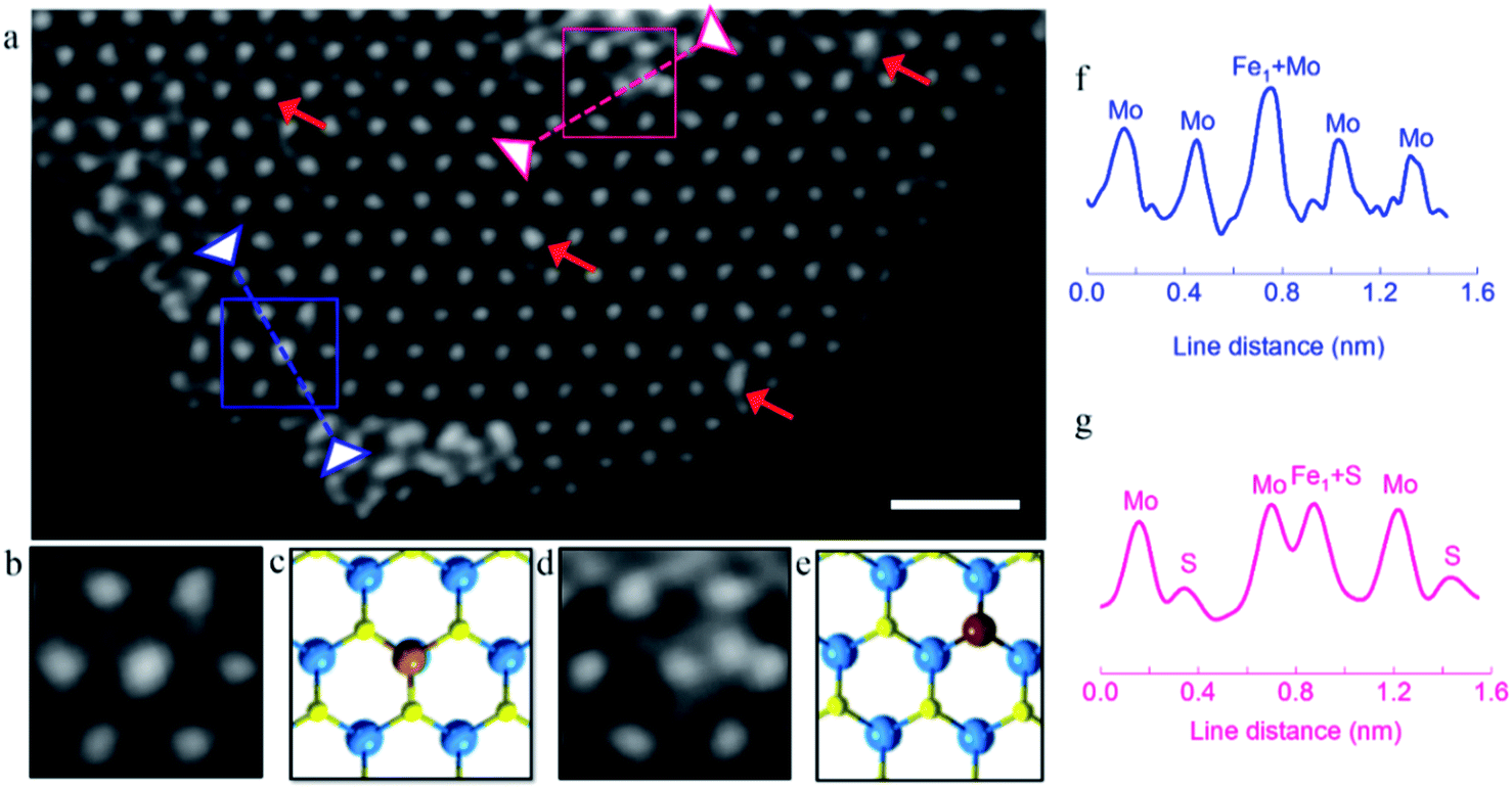 | ||
| Fig. 1 Morphology and structural characterization of Fe-sMoS2. (a) HAADF-STEM image of Fe-sMoS2 sheet, scale bar is 1 nm. Chemical environments of Fe1 can be seen in the two enlarged square boxes, where Scan 1 (blue line) shows the Fe1 atom on the Mo atop site and Scan 2 (pink line) shows the Fe1 atom substituted on the S site. The red arrows indicate individual Fe1 atoms on the Mo atop site. (b) HAADF-STEM scan, (c) corresponding DFT optimized model and (f) ADF intensity profile analysis of the Fe1 atom on the Mo atop site. (d) HAADF-STEM scan, (e) corresponding DFT optimized model and (g) ADF intensity profile analysis of the Fe1 atom as the substituted S site. | ||
To obtain bonding information on the anchored Fe1 atom, experimental XAFS (Fig. 2a) spectra were collected together with DFT simulations. Fig. 2a shows the Fourier transform spectrum of the Fe K-edge XAFS oscillations of the as-reduced Fe-sMoS2 in comparison with the standard Fe foil. The absence of Fe–Fe interaction in the FT-XAFS spectra indicates the single-atom configuration of Fe1. The peak at approximately 1.7 Å is mainly attributed to the Fe–S bonds at the Mo atop site. The simulation of the structure with the corresponding bonding distance is shown in the inset of Fig. 2a. Wavelet transformed analysis of XAFS (WT-XAFS, Fig. 2c) based on Morlet wavelets was conducted to differentiate the closely-related spatial interactions26 of the Fe1 atoms with their proximal atoms. As displayed in Fig. 2c, the Fe–Fe bonds in the Fe foil show an energy maximum in the range of 7–11 Å−1, while that for Fe-sMoS2 is in the range of 4–9 Å−1. This again supports the fact that the Fe species are individually dispersed as single atoms, as shown by the HADDF-STEM image (Fig. 1), mainly at the Mo atop sites.
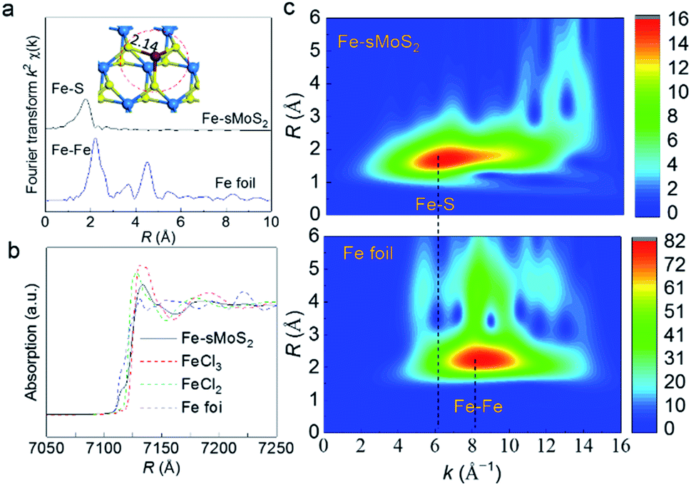 | ||
| Fig. 2 Bonding environment of Fe1 atom in Fe-sMoS2. (a) Fourier transform Fe K-edge XAFS spectra of Fe-sMoS2 with reference to Fe foil. Inset shows the DFT model for Fe1 atom at Mo atop site with the peak matching to that expected from the corresponding Fe–S distance and absence of Fe–Fe in both models. (b) Fe K-edge XANES spectra of atomically dispersed Fe-sMoS2. Fe foil, hydrated FeCl2, and FeCl3 were used as references. (c) Wavelet transformation for the k2-weighted Fe K-edge XAFS signals of Fe-sMoS2 and Fe foil based on Morlet wavelets with optimum resolutions at the first and higher coordination shells. The intensity reflects the content of scattering signals. Intensity decreases in order of red, yellow, green, and blue. | ||
The bonding environment of the Fe1 atom at the Mo atop site was simulated by DFT, and the result is shown in Fig. S5.† Interestingly, the structure in the model of Fe1 at the Mo atop site has almost the same inorganic motif of [Fe–S2–Mo] with that of the core structure of FeMoco, the primary cofactor of nitrogenase, giving equivalent bond lengths and geometries of the coordinated Fe1 shells (see Table S1†).24,27 In addition to the similar bonding environment of Fe, according to the XANES analysis, the absorption edge is clearly located between FeII and FeIII, indicating that the oxidation state of the Fe species in Fe-sMoS2 is also close to that of the working state of FeMoco,28 as shown in Fig. 2b. Of particular interest is the characteristic peak below the absorption edge of Fe-sMoS2. It is well known that this pre-edge feature is due to the 1s → 3d orbital forbidden transition, which would be excluded by dipole selection rules for a symmetry site.29 The observed pre-edge peak matches with the characterized isolated Fe1 on s-MoS2.
Electrochemical N2 reduction
The material was then tested for electrochemical N2 conversion to NH3 in water under ambient conditions. The catalyst was deposited on carbon paper as a cathode under a flowing stream of N2 feed gas. It has been noted in the literature in this field that carefully designed blanks must be employed to confirm the nitrogen reduction reaction activity of any material. For example, it has been reported that contaminants such as NOx may also participate in the synthesis of ammonia.30,31 NaClO2 is known to be one of the most efficient chemicals for NOx oxidation due to its strong oxidation power.32,33 Thus, to remove the interference of NOx, two traps filled with 0.2 M NaClO2 solution and 1 mM H2SO4 solution were used to purify the feed gas before it was flowed into the three-electrode single cell. The ability to remove NOx is evidenced in Fig. S6.† In a previously established N2 purification protocol, gas cleaning of the filters following by acid trapping were employed to remove NOx.34 The two methods were compared, and the results were within an acceptable deviation of 8.3%. Prior to each test, blank measurements in the absence of N2 and catalyst were conducted.35–38 The obtained reaction assay was measured by two independent methods, namely the indophenol blue method (Fig. S7†) and ammonia selective electrode.39 The detail mechanism of the ammonia selective electrode is presented in the ESI.† The calibration curves are shown in Fig. S8 and S9,† respectively. The results from the two methods were in a good agreement. We firstly optimized the over-potential required for the maximum production of NH3 over Fe-sMoS2 in the range of −0.05 V to −1.00 V (versus the reversible H2 electrode (RHE)). As shown in Fig. S10,† the current density increased as the applied potential increased, and was more stable at low potential. The highest rate of NH3 production was 24.5 μgNH3 cm−2 h−1 (8.7 mgNH3 mgFe−1 h−1) at −0.10 V (versus RHE, see Fig. 3a) with a maximum ηFE of ca. 27.0% (Fig. 3b). To the best of our knowledge, this electrocatalytic performance is among the best reported results for the electrochemical synthesis of NH3 using non-noble Fe-based systems in the literature (Table S2†). However, both the rate and ηFE decreased dramatically when the applied potential was beyond −0.20 V (Fig. 3b). The Tafel plot in Fig. S11† was used to determine the rate-determining step for the H2 evolution reaction and oxygen reduction reaction. Mechanistically, three principal steps can participate in the conversion of 2H+ to H2, namely the Volmer, Heyrovsky and Tafel steps. If the Volmer process is the rate-determining step (rds), a slope of ∼120 mV per decade will likely be obtained. In contrast, a rate-determining Heyrovsky or Tafel step gives characteristic slopes between 30–40 mV per decade.40 Our Tafel slope for Fe-sMoS2 in argon gas was measured to be ∼156 mV per decade at a low over-potential range (Fig. S11†), which suggests the rds is the Volmer step, involving the initial highly activated adsorption and reduction of H+ to produce active surface H* (H+ + e− + * = *H). On the other hand, the corresponding Tafel slope for Fe-sMoS2 for N2 reduction to ammonia was measured to be ∼121 mV per decade, which is substantially lower that of the proton reduction. Therefore, to reduce the extent of H2 production on this surface during N2 reduction, it appears to be necessary to apply an optimal potential.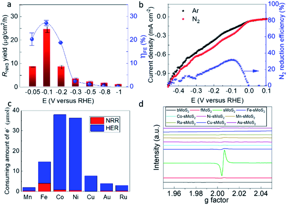 | ||
| Fig. 3 N2 reduction in aqueous solution and relationship between activity and structure. (a) N2 reduction activity to NH3 over Fe-sMoS2 under applied potentials in the range of −0.05 V to −1.00 V. Activity was evaluated at least 3 times under the same conditions to generate the measurement errors for the ammonia production rate (RNH3) and faradaic efficiency (ηFE). (b) Linear sweep voltammetry from 0.10 V to −0.50 V versus RHE over Fe-sMoS2 under Ar and N2. N2 reduction efficiency for NH3 production at different applied potentials was extrapolated from the linear sweep voltammetry curves. The NH3 yield is expressed as μg cm−2 h−1 (μgNH3 per centimeter square of electrode per hour). (c) Calculated amount of electrons consumed for the nitrogen reduction reaction (NRR) and hydrogen evolution reaction (HER) at −0.1 V in 1 h over [M–S2–Mo] (M represents metal as shown in x-axis) dwelling in single-layered MoS2 assuming no heat was generated from the current. (d) Electron paramagnetic resonance spectra of over different thickness MoS2 samples and transition metals. | ||
It is well known that exposed lattice vacancies can act as active sites for the activation of H2 and N2.41–43 Consequently, different concentrations of S vacancies in different-layered MoS2 samples using electron paramagnetic resonance were obtained (EPR, Fig. 3d). As can be seen in Fig. 3d, the peak intensity due to S vacancies (unpaired electrons at g = 2.00 detected infer the formation of S vacancies) increased with S decrease in the thickness of the MoS2 layers (S vacancies were created during exfoliation25), which correlates well with their electrochemical performances at a potential of −0.1 V (versus RHE, Fig. 3d and S12†). The activity for both N2 reduction and H2 evolution appeared to be greatly promoted when single-layered MoS2 was used. Notably, the activity for NH3 yield apparently increased with a reduction in the thickness of the MoS2 slab. However, the overall ηFE for N2 reduction to NH3 by the single-layered MoS2 was significantly lower than that of few-layered MoS2 and bulk MoS2. This implies that S vacancies promote a greater degree of H2 evolution than N2 reduction due to the more favorable thermodynamics in the former case. The addition of a transition metal causes an obvious decrease in the EPR signal, presumably because the transition metal dopant can occupy the S vacancies of 2H-MoS2, as shown by the HAADF-STEM analysis (Fig. 1c). Fe-sMoS2 exerts strong magnetic perturbation due to the presence of paramagnetic Fe, which accounts for the perturbed zig-zag oscillation of the background ESR signal. Fig. S13† shows a comparison of the activities and ηFE for N2 reduction to NH3 over different metal-doped sMoS2 such as Au and Ru with the previously reported values.44,45 The presence of trace Li+ during the preparation of the molecular layer of MoS2 may facilitate the activity and ηFE since Li+ has been reported to play a vital role in the NRR.46 However, the result from Fig. S13† indicates that the metal doping affects much more than the residual Li+. Polarization due to protruded transition metal atoms on the thin MoS2 surface suggested by L. Zhang and co-workers may play a role in their activity.47 However, we believe that the intrinsic atomic arrangements of Fe-sMoS2, which has the core structure of nitrogenase, can give the best activity and ηFE. In fact, among the Haber–Bosch catalysts and biological enzymes, Fe is well-known to bind N and H competitively to give ammonia compared to other metals. This is further supported by the high electron consumption for the nitrogen reduction reaction over Fe-sMoS2, as shown in Fig. 3c.
The electrochemical performance for N2 fixation to NH3 on Fe-sMoS2 was also studied by linear sweep voltammetry (LSV). As shown in Fig. 3b, a clearly higher cathodic current density can be observed in the sweeping potential range of −50 mV to −300 mV versus RHE when the electrolyte was purged with N2 instead of Ar. In addition, the ηFE for N2 reduction by dividing the current density in Ar is very close to that in the synthesis of NH3 (maximum of 27%), verifying that N2 is activated and converted to NH3 by the Fe-sMoS2 catalyst. Isotopic labeling using 98% 15N-enriched N2 gas was carried out to prove the derivation of NH3. Controlled experiments in the absence of 15N2, catalyst, and applied potential were firstly conducted, and no clear ammonia signal was observed in the proton NMR spectra, as shown in Fig. S14.† In contrast, a doublet in the region near 7.0 ppm was found for the test over Fe-sMoS2 at −0.10 V with a flow of 15N2. The quantitative results (Fig. S15†) indicated that the product rate is around 22 μg cm−2 h−1, which is consistent with the result using 14N2. These results show that both the catalyst and the applied potential are necessary for nitrogen fixation. Thus, based on the result from LSV, nitrogen fixation occurs at a potential in the range of 0 to −0.5 V. Subsequently, liquid chromatography-mass spectrometry (LC-MS) analysis was conducted, which identified two major species containing indophenol derivatives from natural 14N and enriched 15N (see Fig. S16†).17,48 The fragments containing 15N have a much higher area ratio at 199/198 m/z (mass/charge ratio) compared to that of the control fragments containing 14N. The isotopically labeled 15N2 authenticated that the NH3 synthesized originated from N2 reduction. These results gave sufficient proof that N2 can be fixed to NH3 over Fe-sMoS2. We conducted a 10 h chronoamperometry test, which demonstrated that the activity and ηFE slightly changed, as shown in Fig. S17.†
Molecular activation and reduction of N2
Operando Fe K-edge opXAFS and opXANES are sensitive techniques to monitor the chemical environment of Fe atoms, which were performed in this study at the B18 Beamline, Diamond Light Source, UK to study the structural dynamics involving the single Fe atoms upon the competitive adsorption and activation of N2 with a proton from water over Fe-sMoS2. Fig. 4a and c show the Fourier transform (FT) opEXAFS spectra and the corresponding Fe K-edge opXANES spectra under different experimental conditions. Particularly, the peak relative to the Fe–S bond attributed to the Mo atop site (see Fig. 3a) under open-circuit voltage is compared in N2, Ar/H2O, and N2/H2O, and at −0.1 V (versus RHE) in N2/H2O. It is clear that the FT intensity near the Fe–S bonds at the Mo atop site clearly changes in this region to the different treatments. After switching to highly acidic electrolyte solution purged with Ar, the intensity of the Fe–S peak attributed to the Fe atop site exhibited the lowest value, which indicates the lowest coordination number for this Fe species. Based on our DFT simulation, the Fe–N bonding interactions of these molecule-absorbed Fe-sMoS2 species are at around 1.8 Å (Fig. S18†), which is comparable in distance with the Fe–S interactions. Thus, it was anticipated that competitive replacement of this absorbed N2 species from Fe by H+ would cause a reduction in the intensity of this peak. Interestingly, upon switching the gas stream back to N2, we noted that the peak intensity increased to a higher value, resuming the higher contribution from the Fe–N scattering. These results clearly show that N2 and H+ can be competitively activated by the Fe1 atoms on MoS2, as reflected by the atop Fe–S peak modulations. During the typical conditions for electrochemical N2 reduction to NH3 at the previously optimized −0.1 V versus RHE, the intensity of opXAFS was significantly enhanced, which implies that the dynamic N2 adsorption to NH3 was greatly strengthened, corresponding to the same phenomenon observed in Fig. 3a. This also indicates that the electron from the applied potential is biased at the Fe1 atom and could be used for competitive N2 activation to NH3. In addition, the Fourier transform spectra showed that there was a slight but significant shift in the Fe–S interaction of the atop site during N2 activation, as shown in Fig. 4a. The main peak of Fe–S shifted to a shorter length (∼Δ 0.04 Å) upon switching to Ar flushing and returned to the original position when the N2 flow was resumed. Clearly, the electron back-donation of Fe orbitals from the adsorbed N2 can attenuate its bonding with the S ligands, accounting for the longer Fe–S interaction. Apparently, applying a negative over-potential for N2 over H+ in the dynamic synthesis of ammonia places the peak position between these two values.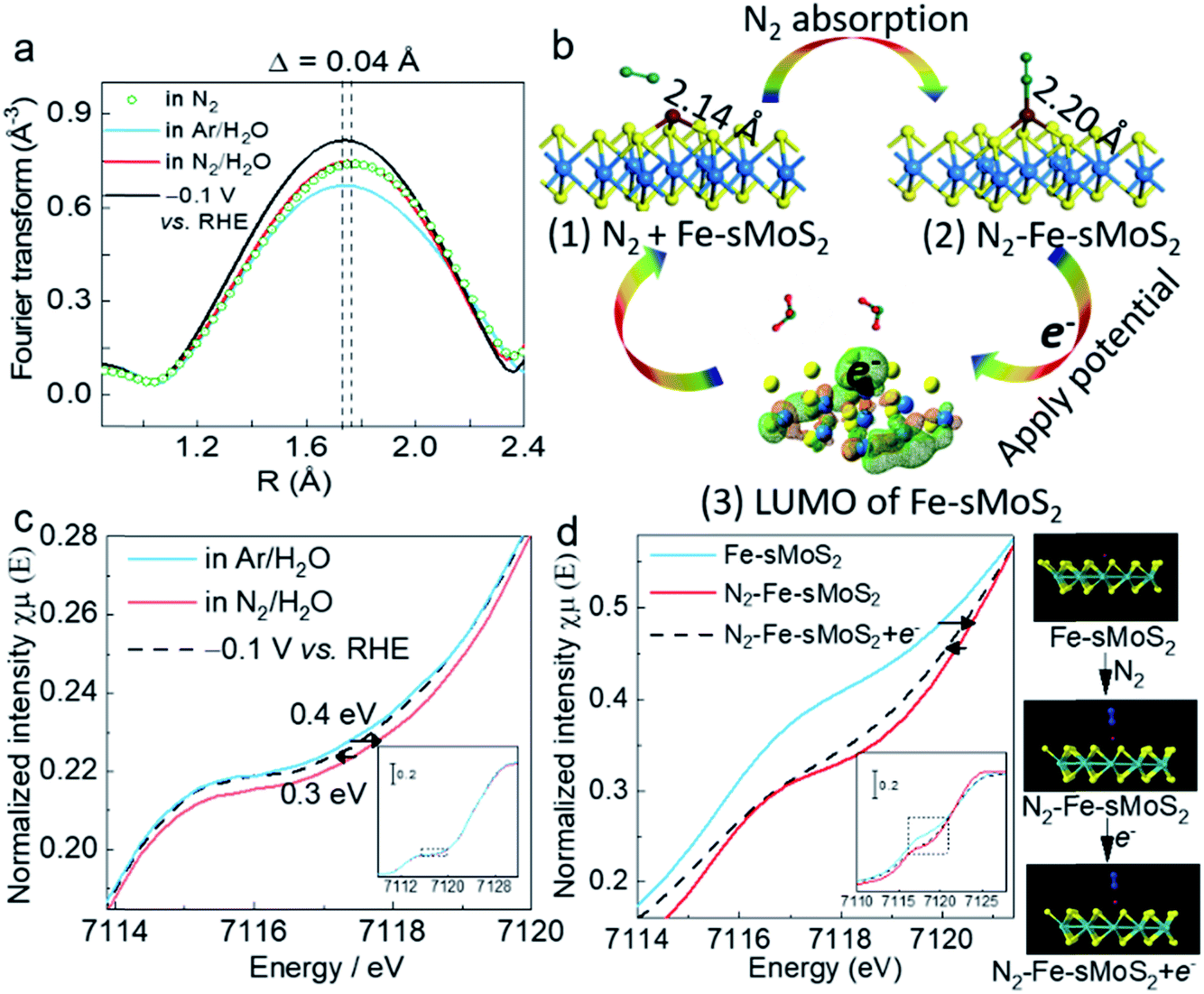 | ||
| Fig. 4 Operando X-ray absorption spectroscopy and N2 activation process. (a) Fourier transform magnitudes of the experimental Fe K-edge srXAFS spectra of Fe-sMoS2 under open-circuit voltage bias in N2, Ar/H2O, and N2/H2O, and at −0.1 V (versus RHE) in N2/H2O. H2O represents electrolyte solution containing 0.1 M hydrogen chloride. (b) Structural evolution of the active site in electrochemical NH3 synthesis with N2 absorption and applied potential. (1) Before N2 adsorption, the Fe–S bond is 2.14 Å in length. (2) After the adsorption of N2 on the Fe1 atom, the Fe–S bond is extended to 2.20 Å in length. (3) Low unoccupied molecular orbital of Fe1 Mo atop site. Green net represents positively charged orbital and orange net represents negatively charged orbital. After applying a potential, the electron will transfer to the Fe1 atom. Blue, yellow, brown, green, and red balls are Mo, S, Fe, N, and H atoms, respectively. (c) Normalized operando Fe K-edge XANES spectra for Fe-sMoS2 under open-circuit voltage bias in Ar/H2O, and N2/H2O, and at −0.1 V (versus RHE) in N2/H2O. (d) Simulated Fe K-edge XANES spectra for Fe-sMoS2, N2-adsorbed Fe-sMoS2, and N2-adsorbed Fe-sMoS2 with electron-rich Fe. Blue, yellow, brown, cyan, and red balls are N, S, Fe, and Mo atoms, respectively. | ||
The processes for N2 activation were then investigated by DFT calculations (Fig. S19†). Fig. 4b(1) shows that the DFT-optimised Fe–S bond of the initial Fe1 atom at the Mo atop site is 2.14 Å. After the absorption of N2, the bond is extended by absorbed N2 to 2.20 Å (Fig. 4c(2)). The increment in the bond length (∼0.06 Å) is close to the observed value (∼0.04 Å), as measured by opXAFS. The electron ground state of Fe-sMoS2 was simulated in the form of the highest occupied molecular orbital (HOMO). As shown in Fig. 4c(3), Fe1 is relatively positively charged under N2, which allows the external electrons to occupy it under HOMO excitation. The experimental result from opXAFS also confirmed that the external electrons from the applied potential will be accommodated at the Fe1 atom, as above. Therefore, the electron can then be used for the activation and reduction of N2 to NH3 on [Fe–S2–Mo].
Fig. 4c shows the corresponding normalized operando Fe K-edge opXANES spectra in Ar. The shoulder signal of the main absorption edge at ∼7118 eV is due to the 1s → 4p transition. The introduction of N2 caused a shift to the right, showing an electron withdrawing effect from the Fe species to N2, indicating the electronic effects on the Fe1 atom via N2 adsorption. The shift to a higher oxidative state is due to the effective delocalization of the unpaired electron in the 3d orbitals of Fe and the spontaneous charge transfer from Fe to both the N2 2p orbital and proton 1s orbital. During electrochemical N2 reduction, the Fe K-edge of Fe-sMoS2 shifted back to a lower shift value, indicating the recovery of the electronic state of the orbitals of Fe1 due to the injection of external electrons. We further monitored this process using XANES simulations for Fe-sMoS2 under different conditions (Fig. 4d). As shown, the N2 adsorption on the Fe1 atom significantly shifted the edge of 1s → 4p transition, which returned to a lower energy value after applying one electron to the Fe atom. The simulations confirmed the trend of the effect of N2 activation and potential applied. Similar phenomena of opXAFS and opXANES were observed for the molecular activation and reduction of CO2.49
Thus, based on these operando studies, the Fe1 single atom on Fe-sMoS2 serves as the active site for the electrochemical fixation of N2 to NH3. During the adsorption and electrochemical reduction of N2, [Fe–S2–Mo] responds to the tension and contraction of the Fe–S bond by changing the bond length and Fe electronic state.
To demonstrate the electron-mediating and catalytic roles of the [Fe–S2–Mo] unit in promoting the synthesis of ammonia, we compared the electronic structure of N2–Fe-sMoS2 and N2–Fe3S4. As shown in Fig. 5, the Bader charge of adsorbed N2 is −0.29 electrons (−0.01–0.28) over Fe-sMoS2. This value is much lower than that (0.23–0.43 = −0.20 electrons) over Fe3S4, indicating that more electrons are donated from the Fe1 site to the antibonding orbital of the adsorbed N2 on Fe-sMoS2 with [Fe–S2–Mo] units than Fe3S4 without Mo. Consequently, the activation of N2 is promoted with a longer N–N bond length from 1.10 Å to 1.15 Å (see Table S3†). Meanwhile, the bond length of Fe–N is shortened within the unit of [Fe–S2–Mo]. In addition, the average Bader charge of the S atom in the [Fe–S2–Mo] unit is also more negative than that without the nitrogenase-mimic structure (−0.61 vs. −0.54 electrons), indicating that the removal of a proton from the competitive active site of the Fe atom is easier for a higher efficiency of nitrogen reduction over the nitrogenase mimic Fe-sMoS2 under the same potential.
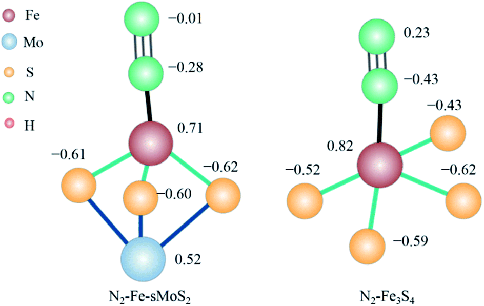 | ||
| Fig. 5 Electronic structure of N2 activation over nitrogenase-mimic Fe-sMoS2 and Fe3S4. The presented data is the Bader charge of the corresponding atoms in units of electrons. | ||
Conclusions
In summary, a new inorganic-based electrocatalyst with Fe1 on a 2D single-layer MoS2 slab was described. The structure contained dispersed Fe atoms on nitrogenase-like [Fe–S2–Mo] motifs, which showed superior electrochemical activity and ηFE for electrochemical N2 fixation to NH3 over proton reduction in water under the application of the optimal potential at 0.1 V. Operando Fe K-edge srXAFS, XANES and DFT calculations indicated that N2 can be adsorbed and reduced at the catalytic Fe1 site on the essential electron-mediating [Fe–S2–Mo] motifs. To activate the N2 molecule, the strain of the Fe–S bonds and redox states of the Fe1 atom will adapt to accelerate the absorption and reduction processes. This work not only demonstrated that single-atom heterogeneous catalysis accelerates the electrochemical reduction of N2, but also offers unique insight into the synergistic active site with electronic and structural transitions during N2 fixation over the nitrogenase mimic [Fe–S2–Mo] structure.Conflicts of interest
The authors declare no competing financial interest.Acknowledgements
The support of this project from the IUK-EPSRC of UK (DGE 102000) is gratefully acknowledged. The authors wish to thank Diamond Light Source (Diamond, UK) for accessing STEM and XAS facilities (B18; SP20856-1). LL also acknowledges the use of the Computing Facilities of Wuhan University of Science and Technology in the completion of the theoretical part of this work.Notes and references
- J. G. Chen, R. M. Crooks, L. C. Seefeldt, K. L. Bren, R. M. Bullock, M. Y. Darensbourg, P. L. Holland, B. Hoffman, M. J. Janik, A. K. Jones and M. G. Kanatzidis, Science, 2018, 360, eaar6611 CrossRef
.
-
E. Worrell, L. Price, M. Neelis, C. Galitsky and Z. Nan, World best practice energy intensity values for selected industrial sectors, Tech. Rep., LBNL-62806 Ernest Orlando Lawrence Berkeley National Laboratory, 2008 Search PubMed
- D. Tilman, K. G. Cassman, P. A. Matson, R. Naylor and S. Polasky, Nature, 2002, 418, 671–677 CrossRef CAS
- H. Wang, L. Wang, Q. Wang, S. Ye, W. Sun, Y. Shao, Z. Jiang, Q. Qiao, Y. Zhu, P. Song and D. Li, Angew. Chem., Int. Ed., 2018, 57, 12360–12364 CrossRef CAS
- H. Li, J. Shang, Z. Ai and L. Zhang, J. Am. Chem. Soc., 2015, 137, 6393–6399 CrossRef CAS
- L. Ye, R. Nayak-Luke, R. Banares-Alcantara and E. Tsang, Chem, 2017, 3, 712–714 CAS
- J. Zheng, F. Liao, S. Wu, G. Jones, T. Y. Chen, J. Fellowes, T. Sudmeier, I. J. McPherson, I. Wilkinson and S. C. E. Tsang, Angew. Chem., Int. Ed., 2019, 58, 17335–17341 CrossRef CAS
- S. Chen, S. Perathoner, C. Ampelli, C. Mebrahtu, D. Su and G. Centi, Angew. Chem., Int. Ed., 2017, 56, 2699–2703 CrossRef CAS
- R. D. Milton, R. Cai, S. Sahin, S. Abdellaoui, B. Alkotaini, D. N. Leech and S. D. Minteer, J. Am. Chem. Soc., 2017, 139, 9044–9052 CrossRef CAS
- H. Hirakawa, M. Hashimoto, Y. Shiraishi and T. Hirai, J. Am. Chem. Soc., 2017, 139, 10929–10936 CrossRef CAS
- H. Tao, C. Choi, L. X. Ding, J. Zheng, Z. Han, M. Jia, Q. Fan, Y. Gao, H. Wang, A. W. Robertson, S. Hong, Y. Jung, S. Liu and Z. Sun, Chem, 2019, 5, 204–214 CAS
- E. J. Vicente and D. Dean, Proc. Natl. Acad. Sci. U. S. A., 2017, 114, 3009–3011 CrossRef CAS
- B. M. Hoffman, D. Lukoyanov, Z.-Y. Yang, D. R. Dean and L. C. Seefeldt, Chem. Rev., 2014, 114, 4041–4062 CrossRef CAS
- T. Kandemir, M. E. Schuster, A. Senyshyn, M. Behrens and R. Schlögl, Angew. Chem., Int. Ed., 2013, 52, 12723–12726 CrossRef CAS
- M. J. Chalkley, T. J. Del Castillo, B. D. Matson, J. P. Roddy and J. C. Peters, ACS Cent. Sci., 2017, 3, 217–223 CrossRef CAS
- J. S. Anderson, J. Rittle and J. C. Peters, Nature, 2013, 501, 84–87 CrossRef CAS
- A. Banerjee, B. D. Yuhas, E. A. Margulies, Y. Zhang, Y. Shim, M. R. Wasielewski and M. G. Kanatzidis, J. Am. Chem. Soc., 2015, 137, 2030–2034 CrossRef CAS
- J. Liu, M. S. Kelley, W. Wu, A. Banerjee, A. P. Douvalis, J. Wu, Y. Zhang, G. C. Schatz and M. G. Kanatzidis, Proc. Natl. Acad. Sci. U. S. A., 2016, 113, 5530–5535 CrossRef CAS
- B. M. Lindley, A. M. Appel, K. Krogh-Jespersen, J. M. Mayer and A. J. Miller, ACS Energy Lett., 2016, 1, 698–704 CrossRef CAS
- D. R. Cummins, U. Martinez, A. Sherehiy, R. Kappera, A. Martinez-Garcia, R. K. Schulze, J. Jasinski, J. Zhang, R. K. Gupta and J. Lou, Nat. Commun., 2016, 7, 11857 CrossRef CAS
- J. H. Montoya, C. Tsai, A. Vojvodic and J. K. Nørskov, ChemSusChem, 2015, 8, 2180–2186 CrossRef CAS
- C. J. Jacobsen, S. Dahl, B. S. Clausen, S. Bahn, A. Logadottir and J. K. Nørskov, J. Am. Chem. Soc., 2001, 123, 8404–8405 CrossRef CAS
- K. M. Lancaster, M. Roemelt, P. Ettenhuber, Y. Hu, M. W. Ribbe, F. Neese, U. Bergmann and S. DeBeer, Science, 2011, 334, 974–977 CrossRef CAS
- J. Chen, J. Christiansen, N. Campobasso, J. T. Bolin, R. C. Tittsworth, B. J. Hales, J. J. Rehr and S. P. Cramer, Angew. Chem., Int. Ed., 1993, 32, 1592–1594 CrossRef
- G. Liu, A. W. Robertson, M. M. Li, W. C. Kuo, M. T. Darby, M. H. Muhieddine, Y. C. Lin, K. Suenaga, M. Stamatakis, J. H. Warner and S. C. E. Tsang, Nat. Chem., 2017, 9, 810–816 CrossRef CAS
- H. Fei, J. Dong, M. J. Arellano-Jimenez, G. Ye, N. D. Kim, E. L. Samuel, Z. Peng, Z. Zhu, F. Qin, J. Bao and M. J. Yacaman, Nat. Commun., 2015, 6, 8668 CrossRef CAS
- R. Bjornsson, F. Neese, R. R. Schrock, O. Einsle and S. DeBeer, J. Biol. Inorg Chem., 2015, 20, 447–460 CrossRef CAS
- R. Bjornsson, F. A. Lima, T. Spatzal, T. Weyhermüller, P. Glatzel, E. Bill, O. Einsle, F. Neese and S. DeBeer, Chem. Sci., 2014, 5, 3096–3103 RSC
- A. Kropf, B. Bunker, M. Eisner, S. Moss, L. Zecca, A. Stroppolo and P. Crippa, Biophys. J., 1998, 75, 3135–3142 CrossRef CAS
- J. Jakob, J. K. Norskov and I. Chorkendorff, ACS Energy Lett., 2019, 4, 2986–2988 CrossRef
- J. Long, S. Chen, Y. Zhang, C. Guo, X. Fu, D. Deng and J. Xiao, Angew. Chem., Int. Ed., 2020, 59, 9711–9718 CrossRef CAS
- A. Pourmohammadbagher, E. Jamshidi, H. Ale-Ebrahim and S. Dabir, Ind. Eng. Chem. Res., 2011, 50, 8278–8284 CrossRef CAS
- C. Brogren, H. T. Karlsson and I. Bjerle, Chem. Eng. Technol., 1998, 21, 61–70 CrossRef CAS
- B. R. Deshwal, D. S. Jin, S. H. Lee, S. H. Moon, J. H. Jung and H. K. Lee, J. Hazard. Mater., 2008, 150, 649–655 CrossRef CAS
- J. Choi, H. L. Du, C. K. Nguyen, B. H. Suryanto, A. N. Simonov and D. R. MacFarlane, ACS Energy Lett., 2020, 5, 2095–2097 CrossRef CAS
- L. F. Greenlee, J. N. Renner and S. L. Foster, ACS Catal., 2018, 8, 7820–7827 CrossRef CAS
- S. Z. Andersen, V. Colic, S. Yang, J. A. Schwalbe, A. C. Nielander, J. M. McEnaney, K. Enemark-Rasmussen, J. G. Baker, A. R. Singh, B. A. Rohr, M. J. Statt, S. J. Blair, S. Mezzavilla, J. Kibsgaard, P. C. K. Vesborg, M. Cargnello, S. F. Bent, T. F. Jaramillo, I. E. L. Stephens, J. K. Norskov and I. Chorkendorff, Nature, 2019, 570, 504–508 CrossRef CAS
- C. Tang and S. Z. Qiao, Chem. Soc. Rev., 2019, 48, 3166–3180 RSC
- Y. Ma, T. Yang, H. Zou, W. Zang, Z. Kou, L. Mao, Y. Feng, L. Shen, S. J. Pennycook, L. Duan, X. Li and J. Wang, Adv. Mater., 2020, 2002177 CrossRef CAS
- T. Shinagawa, A. T. Garcia-Esparza and K. Takanabe, Sci. Rep., 2015, 5, 13801 CrossRef
- T. Wu, Z. Xing, S. Mou, C. Li, Y. Qiao, Q. Liu, X. Zhu, Y. Luo, X. Shi and Y. Zhang, Angew. Chem., Int. Ed., 2019, 58, 18449–18453 CrossRef CAS
- C. Lv, Y. Qian, C. Yan, Y. Ding, Y. Liu, G. Chen and G. Yu, Angew. Chem., Int. Ed., 2018, 57, 10246–10250 CrossRef CAS
- H. Li, C. Tsai, A. L. Koh, L. Cai, A. W. Contryman, A. H. Fragapane, J. Zhao, H. S. Han, H. C. Manoharan and F. Abild-Pedersen, Nat. Mater., 2016, 15, 48–53 CrossRef CAS
- S. J. Li, D. Bao, M. M. Shi, B. R. Wulan, J. M. Yan and Q. Jiang, Adv. Mater., 2017, 29, 1606550 CrossRef
- B. H. Suryanto, D. Wang, L. M. Azofra, M. Harb, L. Cavallo, R. Jalili, D. R. G. Mitchell, M. Chatti and D. R. MacFarlane, ACS Energy Lett., 2018, 4, 430–435 CrossRef
- G.-F. Chen, X. Cao, S. Wu, X. Zeng, L.-X. Ding, M. Zhu and H. Wang, J. Am. Chem. Soc., 2017, 139, 9771–9774 CrossRef CAS
- J. Li, S. Chen, F. Quan, G. Zhan, F. Jia, Z. Ai and L. Zhang, Chem, 2020, 6, 808–810 Search PubMed
- Y. Zhao, Y. Zhao, R. Shi, B. Wang, G. I. Waterhouse, L. Z. Wu, C. H. Tung and T. Zhang, Adv. Mater., 2019, 31, 1806482 CrossRef
- H. B. Yang, S.-F. Hung, S. Liu, K. Yuan, S. Miao, L. Zhang, X. Huang, H.-Y. Wang, W. Cai and R. Chen, Nat. Energy, 2018, 3, 140–147 CrossRef CAS
Footnote |
| † Electronic supplementary information (ESI) available. See DOI: 10.1039/d0sc04575f |
| This journal is © The Royal Society of Chemistry 2021 |