
Impact of structure, doping and defect-engineering in 2D materials on CO2 capture and conversion
E. J.
Jelmy
a,
Nishanth
Thomas
 bc,
Dhanu Treasa
Mathew
a,
Jesna
Louis
ad,
Nisha T.
Padmanabhan
a,
Vignesh
Kumaravel
bc,
Honey
John
ad and
Suresh C.
Pillai
*bc
bc,
Dhanu Treasa
Mathew
a,
Jesna
Louis
ad,
Nisha T.
Padmanabhan
a,
Vignesh
Kumaravel
bc,
Honey
John
ad and
Suresh C.
Pillai
*bc
aDepartment of Polymer Science and Rubber Technology, Cochin University of Science and Technology, Kerala, India
bNanotechnology and Bio-engineering Research Group, Department of Environmental Science, Institute of Technology Sligo, Sligo, Ireland. E-mail: pillai.suresh@itsligo.ie
cCentre for Precision Engineering, Materials and Manufacturing Research (PEM), Institute of Technology Sligo, Sligo, Ireland
dInter University Centre for Nanomaterials and Devices, Cochin University of Science and Technology, Kerala, India
First published on 27th July 2021
Abstract
The investigations on anthropogenic carbon dioxide (CO2) capture and conversion play a vital role in eradicating global warming and the energy crisis. In this context, defect-engineered two-dimensional (2D) nanomaterials have received much attention in recent years. Herein, the significance of 2D nanomaterials such as graphene, transition metal dichalcogenides, hexagonal boron nitride, MXenes, graphitic carbon nitride, metal/covalent organic frameworks, nanoclays, borophenes, graphynes and green phosphorenes for CO2 capture and conversion has been emphasized. Further, the intrinsic mechanism of CO2 adsorption and conversion is discussed in detail. Theoretical and experimental studies among 2D materials highlight that N-doped porous adsorbents based on graphene and MXenes are more suitable for CO2 adsorption applications. Also, more emphasis is given to outlining and discussing the role of various 2D nanomaterials and their hybrids as photocatalysts, electrocatalysts, photoelectrocatalysts, and thermocatalysts to transform CO2 into valuable products. Although immense efforts are deployed in developing 2D catalysts for the conversion of CO2, challenges such as agglomeration, poor yield, difficulties in analysing the 2D structures for catalytic factors, poor knowledge and in-depth understanding of the reaction mechanisms, high cost, etc. limit their large scale production and commercialization. More detailed theoretical and experimental investigations are required to develop 2D nanostructures with optimum properties for large-scale capture and conversion of CO2.
 E. J. Jelmy | Jelmy E. J. obtained her Ph.D. in Chemistry from Amrita Vishwa Vidyapeetham University, India, in 2016. She completed her post-graduation in Applied Chemistry at Calicut University, Kerala. Since June 2018, she has worked at Cochin University of Science and Technology as a Post-Doctoral Fellow. Her research interests are in the development of conducting polymer-based nanocomposites for energy and environmental applications. She is currently pursuing her research specifically on supercapacitors, triboelectric nanogenerators, and adsorption of pollutant dyes & CO2 gas using graphene/conducting polymer aerogels. |
 Nishanth Thomas | Nishanth Thomas is a Ph.D. candidate in the Nanotechnology and Bio-Engineering Research Group at the Institute of Technology Sligo, Ireland. He completed his BSMS dual degree in Chemistry (major) with a minor in Biology at the Indian Institute of Science Education and Research (IISER) Bhopal, India. During his master's thesis, he investigated the shape-selective synthesis of silver nanostructures by a modified polyol method. Currently, he is working in the EU-Horizon 2020 PANI-WATER Research project for developing Advanced Oxidation Processes (AOPs) for the removal of contaminants of emerging concern (CECs) and antimicrobial-resistant bacteria (ARB) from water. His research interest involves the design of unique nanomaterials for sustainable environment and energy applications. |
 Dhanu Treasa Mathew | Dhanu Treasa Mathew received her Master of Science in Pure Chemistry in 2016 and is currently a Ph.D. scholar in the Department of Polymer Science and Rubber Technology at Cochin University of Science and Technology (CUSAT). Her research interests are focused on the fabrication and development of triboelectric nanogenerators based on eco-friendly materials. |
 Jesna Louis | Jesna Louis is a fourth year PhD student in the Department of Polymer Science and Rubber Technology, Cochin University of Science and Technology, India. Her research interests center around the opto-electronic application of semiconductor oxides and their organic/inorganic hybrids. She received her bachelor's degree and master's degree in Chemistry from the Indian Institute of Science Education and Research (Bhopal, India). |
 Nisha T. Padmanabhan | Nisha T. Padmanabhan joined Cochin University of Science and Technology, Kerala, in 2016, for her doctoral studies. Presently as a CSIR-SRF, she is focused on the synthesis of hybrids based on high-energy faceted TiO2 with transition metal dichalcogenides and other graphitic monolayers for various sustainable & energy applications including self-cleaning, superhydrophilicity, hydrogen evolution reactions, etc. She pursued her post-graduation in chemistry at Mahatma Gandhi University, Kerala. |
 Vignesh Kumaravel | Vignesh Kumaravel obtained his PhD in Chemistry from Madurai Kamaraj University, India in 2013. He has established various research laboratories for doctoral students in energy research. Since March 2018, Vignesh has worked at IT Sligo as a Senior Research Fellow in the EU funded Renewable Engine project. His primary research goals are directed towards the development of nanoparticles for carbon dioxide conversion, water treatment, hydrogen production, antimicrobial food packaging polymers/bio-medical implants, high-temperature stable energy storage devices, super-hydrophobic surfaces, etc. He has completed various research projects as a co-PI/PI, sponsored by Malaysian funding agencies. He is acting as an external examiner for Ph.D thesis evaluation in various Indian universities. He is also acting as a reviewer in evaluating research proposals from the government of Chile (Chilean National Science and Technology Commission) and Poland (National Science Centre). As an expert in the field of materials science, he has peer-reviewed more than 50 research papers in various publications such as Elsevier, ACS, Wiley and Springer Journals. He is currently acting as a guest editor in Catalysts, MDPI journals. |
 Honey John | Honey John obtained her Ph.D. from Cochin University of Science and Technology (Kerala, India) in 2004. She joined the Indian Institute of Space Science and Technology (IIST), Trivandrum, in 2007, as a Reader and worked to the grade of Associate Professor. In 2015, she rejoined the Department of PS&RT, CUSAT as a professor. In 2017, she became the honorary Director of Inter University Centre for Nanomaterials and Devices, CUSAT. Her current research areas are triboelectric and piezoelectric nanogenerators, 2D nanoscrolls with magnetic nanoparticles, photocatalytic self-cleaning materials, hydrogen production, aerogels for supercapacitors and pollutant removal, magnetoplasmonics and green tyres. |
 Suresh C. Pillai | Suresh C. Pillai obtained his Ph.D. from Trinity College Dublin and completed his postdoctoral research at California Institute of Technology (Caltech, USA). He is an elected fellow of the UK's Royal Microscopical Society (FRMS) and the Institute of Materials, Minerals and Mining (FIMMM). He also completed an executive MBA at Dublin City University, in 2009. He joined IT Sligo in 2013 as a Senior Lecturer and currently heads the Nanotechnology and Bio-Engineering Research Group. His research interests include the synthesis of nanomaterials for energy and environmental applications. He is the recipient of several awards including the Boyle-Higgins Award 2019, the Industrial Technologies Award 2011, Hothouse Commercialisation Award 2009, Enterprise Ireland Research Commercialization Award 2009, etc. He is an associate editor for the Chemical Engineering Journal and an editorial board member for Applied Catalysis B. |
1. Introduction
Carbon dioxide (CO2) is a significant integrant, which accounts for around 65% of total greenhouse gas emissions. The major impacts of global warming due to CO2 emissions include rising sea levels, ozone layer depletion, dip in water supplies, acidification of the ocean, infectious diseases, unpredictable weather conditions, etc. In this context, carbon capture and storage (CCS) and carbon capture and utilisation (CCU) effectively abate CO2 emissions.1–4 In general, CCS includes various physical and chemical methods and sequestration procedures and so it is implemented via different stages such as CO2 capture, transportation and storage. The standard techniques to capture CO2 include pre-combustion, oxy-fuel combustion and post-combustion. The captured CO2 is compressed, transported and stored into geological reservoirs. In capture processes, the capture and separation of CO2 is carried out through the adsorption using solvents, solid sorbents, pressure/vacuum swing, membrane and cryogenic separation, and chemical looping combustion technologies. In general, CCU includes: 1) direct utilisation of CO2 in the food and packaging industries as a carbonating, packaging and preservative material, 2) direct utilisation of CO2 in enhanced oil and coal-bed methane recovery, 3) conversion of CO2 into chemicals and fuels where CO2 could be used as a building block for the production of value-added products, 4) mineral carbonation, and 5) utilization of CO2 for the cultivation of microalgae for biofuel production5 (Fig. 1).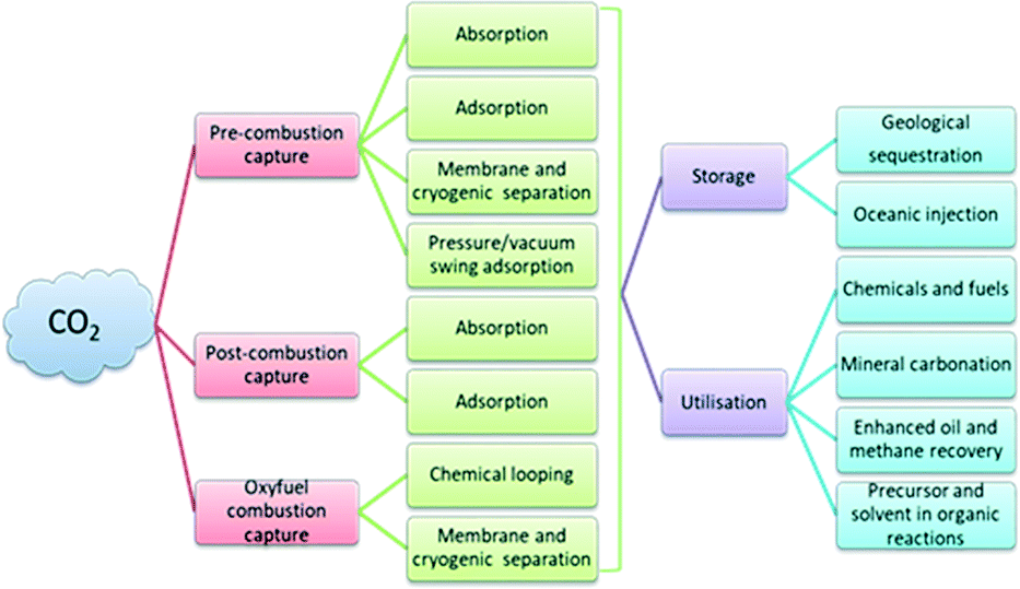 | ||
| Fig. 1 Schematic of the technologies available for CCS and CCU. | ||
In general, capture technologies are based on aqueous amine sorbents requiring a high regeneration cost and therefore the capture of CO2via adsorption using solid adsorbents is preferred.3 The adequate adsorption energy, easy CO2 capture/release process, high selectivity, good thermal and mechanical stability and reusability are the essential criteria for a promising adsorbent. Based on this, several types of carbonaceous and non-carbonaceous materials such as carbon nanotubes, graphene, activated charcoals, polymeric materials, aerogels, zeolites, metal organic frameworks (MOFs), etc. have been proposed to capture CO2.
The catalytic conversion of CO2 to valuable products such as methane, carbon monoxide, acetic acid, formic acid, methanol, ethanol, etc. is an efficient tool for the effective utilization of the stored CO2. However, the major hindrance in the conversion of CO2 to valuable chemicals lies in its thermodynamic inertness and associated high C![[double bond, length as m-dash]](https://www.rsc.org/images/entities/char_e001.gif) O bond dissociation energy (750 kJ mol−1) which is higher than that of C–O, C–C and C–H bonds. The demand for an excessive negative redox potential (Eoredox = −1.90 eV vs. NHE) for the electron transfer in CO2 to deliver active species makes photocatalytic, electrocatalytic and photoelectrocatalytic conversion tough. On the other hand, thermocatalytic CO2 conversions are carried out at a high temperature and pressure with the catalytic support from alkali and alkaline earth metal-based oxides and hydroxides in order to overcome the thermodynamic stability and inertness of CO2.6 Different sources of CO2 emission and its effective utilization by various techniques are depicted in Fig. 2.
O bond dissociation energy (750 kJ mol−1) which is higher than that of C–O, C–C and C–H bonds. The demand for an excessive negative redox potential (Eoredox = −1.90 eV vs. NHE) for the electron transfer in CO2 to deliver active species makes photocatalytic, electrocatalytic and photoelectrocatalytic conversion tough. On the other hand, thermocatalytic CO2 conversions are carried out at a high temperature and pressure with the catalytic support from alkali and alkaline earth metal-based oxides and hydroxides in order to overcome the thermodynamic stability and inertness of CO2.6 Different sources of CO2 emission and its effective utilization by various techniques are depicted in Fig. 2.
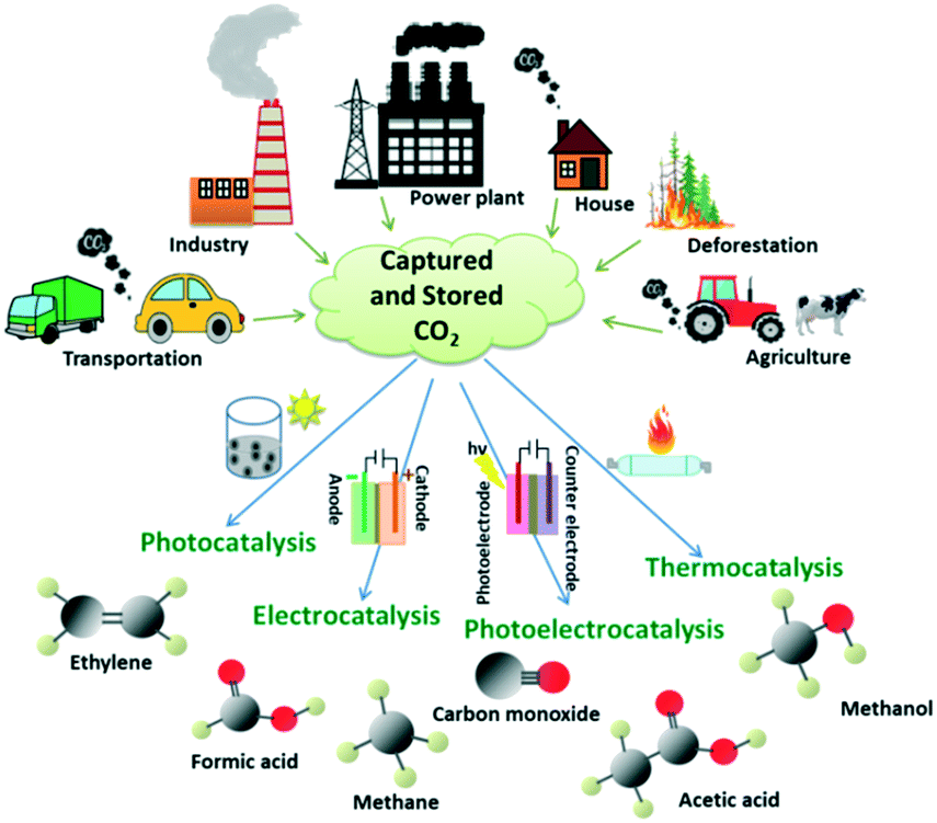 | ||
| Fig. 2 Different sources of CO2 emission and the utilisation of captured/stored CO2 by catalytic conversion to value-added products. | ||
After the discovery of graphene, the research on 2D nanomaterials has proliferated, and a wide range of materials such as transition metal dichalcogenides (TMDCs), hexagonal boron nitride (h-BN), MXenes, graphitic carbon nitrides (g-C3N4), metal/covalent organic frameworks (COFs and MOFs), borophenes, graphynes, green phosphorenes, etc. have been studied. Further, due to the quantum confinement effect in few-layered systems, one can observe exponentially high electronic, optical and mechanical properties when compared to their bulk counterparts. Also, the presence of enduring excitons and trions developed due to the augmented coulombic interactions between charge carriers in semiconducting 2D nanomaterials makes them a prodigious candidate in various disciplines. Further, the enhanced surface area with tuneable physical and chemical properties of 2D materials makes them promising in catalysis, energy storage and optoelectronic applications.7–10 Few-layered 2D nanosheets with unveiled surface atoms have a tendency to escape from the lattice to form defects which in turn can enhance the catalytic performance due to the reduction in the coordination number of the surface atoms. Therefore, the defect engineering of these materials plays a significant role in improving the catalytic performances.11 Due to the aforementioned reasons, the research on catalytic conversion and adsorption of CO2 by 2D materials is considerable.
Several reviews on CO2 capture & storage1–5,12–16 and its catalytic conversion into valuable products17–21 have been published with a prime focus on the technologies. For instance, the recent developments in the use of physisorbents such as carbon nanotubes, graphene, zeolites, silica materials, and MOFs for the removal of CO2 have been addressed.3 Recently the significance of nanomaterials such as MOFs, COFs, zeolites, silicon-based materials, porous organic polymers, layered double hydroxide (LDH)-based materials, metal oxides and nanocarbon materials for the adsorption of CO2 has been reported.1 Further, an analysis on the engineering aspects of MOFs for enhanced CO2 capture and conversion has been reported recently.22 A comparison of CO2 adsorption capacities of 2D materials with traditional solid adsorbents is given in Table 1. Apart from the CO2 adsorption analyses, a recent study highlighted the defect engineering, surface modification and hybrid construction strategies to modify 2D nanomaterials for enhanced photocatalytic reduction of CO2.17 The structural, electronic, thermodynamic and reactive properties of 2D photoelectrocatalysts were examined by Torrisi et al. The major outputs of the study include the investigations on the monolayer phases of selected bulk catalysts and the unconventional chemical behaviour of these materials in CO2 reduction.23 It is reported that there are lot of challenges involved in the electrochemical reduction of CO2 using 2D nanomaterials and the exploration of quantum dots or metal modified porous carbon sheets, heterostructured 2D materials, and inexpensive non-noble 2D metals as electrocatalysts is essential for the future continuation of research in this field.11 In another study, catalytic conversion of CO2 using heteroatom-doped carbon materials has been addressed.24 A comprehensive study on photoelectrochemical conversion of CO2 to value-added products was recently reported with special emphasis on the materials for the electrode, mechanisms, and reactor design.25 Nevertheless, there are no comprehensive reports on the utility of 2D nanomaterials for both CO2 adsorption and conversion by various techniques. Herein, the recent progress and the prominence of 2D materials for CO2 capture, photocatalysis, electrocatalysis, photoelectrocatalysis, and thermocatalysis have been summarized. This article starts with an overview of different techniques for CO2 capture and it is followed by a detailed study of recently suggested 2D nanomaterials and their hybrids such as graphene, TMDCs, h-BN, MXenes, MOFs, COFs, g-C3N4, nanoclays, borophenes, graphynes, green phosphorene, etc. in CO2 adsorption/conversion applications. The structures of common 2D materials used for adsorption and conversion of CO2 are given in Fig. 3.
| Type of adsorbent | Materials used | Operating conditions | Adsorption capacity (mmol g−1) | Ref. | |
|---|---|---|---|---|---|
| Pressure (bar) | Temperature (°C) | ||||
| 2D adsorbents (pristine/doped/defected) | Graphene | 11 | 25 | 21.6 | 26 |
| rGO/N-doped porous carbon composite | 5 | 25 | 5.77 | 27 | |
| Fe3O4/graphene | 11 | 25 | 60 | 28 | |
| PANI/GO | 20 | 27 | 3.2 | 29 | |
| PPy/rGO | 1 | 0 | 6.8 | 30 | |
| Porous BN | 1–20 | 25 | 1.68.3 | 31 | |
| C doped BN | 1 | 0 | ∼5.5 | 32 | |
| MXene, M2N | 1 | 727 | 7.96 | 33 | |
| Ti3C2Tx | 4 | 25 | 5.79 | 34 | |
| g-C3N4 nanosheets functionalized with ionic liquid | 15 | 25 | 42.93 | 35 | |
| Octadecylamine modified MMT | 50 | 25 | 7.16 | 36 | |
| Zeolites | Core–shell zeolite-5A@MOF-74 | 20 | 25 | 13.8 | 37 |
| Zeolite NaX | 1 | 25 | 7.04 | 38 | |
| Li-LSX zeolite | 1 | 60 | 4.43 | 39 | |
| Zeolite SSZ-13 | 1 | 25 | 3.98 | 40 | |
| Activated charcoal | Activated carbon derived from nanocellulose | 1 | 0 | 5.52 | 41 |
| N-Doped activated carbon | 1 | 0 | 5.12 | 42 | |
| Catalytically activated carbon | 1 | 0 | 4.36 | 43 | |
| Physically activated carbon | 1 | 25 | 3.52 | 44 | |
| Activated carbon derived from biomass | 1 | 50 | 1.1 | 45 | |
| MOFs | Amine-functionalized vanadium-based MOF | 1 | 25 | 1.9 | 46 |
| Cu3(NH2BTC)2 MOF | 0.1 | 50 | 1.41 | 47 | |
| Aluminum trimesate-based MOF | 10 | 25 | 10.22 | 48 | |
| In(III)/Pd(II)-Based MOF | 1 | 0 | 4.1 | 49 | |
| MOF/GO composite | 1 | 0 | 6.8 | 50 | |
| Silica | APTES functionalized SBA-15 silica | 1 | 30 | 1.2 | 51 |
| Silica xerogel | 7.5 | 25 | 1.8 | 52 | |
| Amine-grafted mesocellular silica foams | 1 | 60 | 1.54 | 53 | |
 | ||
| Fig. 3 Structures of common 2D materials used for CO2 adsorption and conversion. | ||
2. Fundamentals of carbon dioxide capture
The technologies behind CCS in power plants include pre-combustion capture, oxy-fuel combustion capture and post-combustion capture.2,3,5,15 In pre-combustion capture, as the name indicates, CO2 is captured and stored before the combustion process of the fossil fuel. It can also be defined as a decarbonisation procedure of traditional fuels such as natural gas or coal before producing energy out of them. The two major events involved in this technology are the formation of synthesis gas (syngas) and steam reforming reactions. In this process, the reaction of the fuel with air or O2 leads to the formation of syngas comprising CO and H2.54 The purified syngas undergoes a water-gas shift reaction (WGSR) where CO is treated with steam to produce CO2 and H2. Also, the steam reforming stage delivers H2 (43%), H2O (21%), CO (11%) and CO2 (6%) as major products.55 By physical or chemical absorption, adsorption or separation methods, CO2 is captured and stored for its effective utilisation. In general, the high-pressure CO2 produced in the pre-combustion technique is compressed and liquefied for storage, transportation, and future use. The H2 from the steam reforming process can be purified for use in fuel cells or it can be used to produce valuable chemicals. In the oxy-fuel combustion process, the fuel is combusted with pure oxygen to produce flue gas rich in CO2. The main drawback with this process is the requirement of pure oxygen in massive amounts, which abates its commercialization efforts. Except for this problem, the oxy-fuel combustion process is an attractive one with easy CO2 separation, reducing the volume of flue gas and NOx gases with minimal efficacy penalty.14,56 Researchers speculated that it would be the best available CO2-free power generation method once it got commercialized.56 In post-combustion capture, CO2 is separated or removed from the flue gas after fuel combustion. The exhaust flue gas is purified before the capture of CO2 to remove the traces of nitrogen, sulphur, and dust. Out of the different technologies described above, post-combustion carbon dioxide capture is the most significant, especially in power plants since the capture unit can be added to the plant even after constructing the power plant.57Fig. 4 represents the different CO2 capture processes. | ||
| Fig. 4 Schematic of various CO2 capture processes. | ||
Amine-based chemical solvents are used as absorbents to separate H2 and CO2 formed in the pre-combustion and post-combustion processes because of their high CO2 absorption capacity. However, chemical or physical solvents are not encouraged because of their high viscosity, toxicity, flammability, corrosiveness, extensive energy demand especially in the regeneration stage and low H2–CO2 selectivity.2,5,57,58 On the other hand, CO2 uptake using solid adsorbents such as zeolites,59 activated carbons,60,61 and MOFs62 is attractive due to their high CO2 adsorption efficiency, selectivity, low energy requirements, easy recovery and stability.3,63 The curtailed adsorption efficiency of MOFs and activated carbons at elevated temperature is a major issue with the pre-combustion process.2 Therefore CO2 adsorbents based on lithium silicate nanosheets63 and Nd-doped lithium silicate64 were introduced as adsorbents.
The techniques for CO2 adsorption using solid materials include pressure swing adsorption (PSA), vacuum swing adsorption (VSA), temperature swing adsorption (TSA), moisture swing adsorption (MSA), electric swing adsorption (ESA) and temperature vacuum pressure swing adsorption (TVPSA) and out of these, the most commonly used techniques are PSA, VSA and TSA.3 In the PSA technique, pressure higher than 1 bar is used, while in VSA, pressure lower than 1 bar is used and the regeneration of the adsorbent is done by reducing the pressure.12 In TSA, the adsorbent bed is heated to elevate the adsorption temperature and then cooled for desorption. In general, for the separation of CO2 from the flue gas, VSA is considered more efficient than PSA because applying pressure to the large area feed is economically not viable.12 Usually, in CO2 capture by the adsorption process, a spherical column is packed with the adsorbent and CO2 containing gas is passed through the column.1 During the adsorption process, when gas molecules are in the close vicinity of the adsorbent, they got attracted to the electronic environment of the adsorbent surface. The gas molecule–solid surface interaction can result in the reduction of the free energy of the surface, and therefore, more and more gas molecules can be accumulated on the solid surface before adsorption.3 The adsorption process can be physical or chemical depending on the type of interaction between the adsorbent and adsorbate. Due to the absence of chemical bond formation in physical adsorption, the energy penalty for the regeneration of CO2 is more diminutive. In physical adsorption, along with the van der Waals attraction of CO2 and the adsorbent, electric quadrupole moment (EQM)-electric field gradient interactions are also taking place. The value of EQM is the main factor deciding the selectivity of gases and therefore, carbon dioxide molecules with a high EQM value can be adsorbed on the solid surface compared to nitrogen molecules.3 The necessary criteria to be satisfied by the material for an economical and operational implementation of CO2 capture include a significant CO2 adsorption capacity (∼3–4 mmol g−1), high CO2 selectivity, fast adsorption/desorption kinetics, adequate mechanical strength, low heat of adsorption, and low cost. Nanomaterials are promising candidates for the adsorption and catalysis of CO2 because of their large surface-to-volume ratio and the presence of a considerable number of reactive sites. Besides, the affinity of nanomaterials towards the target molecules can be enhanced by surface modification,65,66 making them interesting for CO2 capture and conversion applications.
3. Two-dimensional nanomaterials for CO2 adsorption
Recently, 2D materials such as graphene (or reduced graphene oxide (rGO)),67–72 molybdenum disulphide (MoS2),73–76 h-BN,77–81 MXenes,33,82 2D MOFs & COFs,8,21,83,84 g-C3N4,85 phosphorenes, nanoclays, etc. (Fig. 5) have been used as adsorbents for CO2 capture.86 | ||
| Fig. 5 Schematic of the applications of 2D materials for CO2 adsorption. | ||
3.1 Graphene
Graphene is an excellent 2D material with unique features such as zero bandgap energy, transparency (97.7%),87 high concentration of charges (1013 cm−2),88 charge mobility,89 current density (1.18 × 10⁸ A cm−2),90 mechanical strength (0.2 TPa)91 and thermal conductivity (∼5000 W mK−1).92 The common problem in TSA/VSA/PSA processes for CO2 capture is the temperature instability of the adsorbent, especially in TSA mode. Mechanical disintegration of the adsorbent due to the tight packing of the adsorbent column and the subsequent reduction in the surface area of the adsorbent is an associated concern. Because of the excellent mechanical strength, thermal conductivity and stability of graphene, the compact packing of the adsorbent column is stable even after repeated or cyclic processes.93 This makes graphene-based materials a wonderful candidate to substitute for traditional adsorbents. The main factors deciding the gas adsorption efficiency of graphene are its ultra-microporous structure, availability of active sites, high specific surface area, and the presence of functional groups for better interaction between the adsorbate and adsorbent. The gas adsorption capacities of pristine graphene oxide (GO) or reduced graphene oxide (rGO) can be further improved by various physical94 or chemical activation processes95–97 in which the porosity of the material can be tuned for CO2 capture. Therefore, top-down and bottom-up techniques such as the use of electron beams, nanosphere lithography, barrier-guided chemical vapour deposition, catalytic hydrogenation, photocatalytic oxidation, chemical etching, etc. can be employed to produce and control the lattice98 of graphene to improve CO2 adsorption capacities. Similarly, the removal or introduction of defects in the lattice of graphene can cause an enhancement in CO2 adsorption capacity93 by creating pores with suitable radii to accommodate CO2 gas molecules. In another study, CO2 adsorption states on monolayer epitaxial graphene grown on a SiC (0001) substrate at 30 K were analysed by temperature-programmed desorption (TPD), X-ray photoelectron spectroscopy (XPS), and density functional theory (DFT).71 In this, CO2 gas was introduced onto the sample surface through a pulse gas dosing system. The coverage of CO2 on graphene was determined by XPS and TPD. The analysis showed a physisorption behaviour for CO2 on graphene, confirming the previous results reported.26,99 From the binding energies of CO2 in C 1s and O 1s of XPS spectra, they have inferred that the adsorption and desorption of CO2 on graphene is in the physisorption regime and the nature of interaction between CO2 and graphene was studied by DFT calculations.71 Recently, adsorption-induced clustering of CO2 on graphene nanosheets was studied through computational analysis.68 The results showed that above a particular amount of surface coverage, the CO2 gas molecules that are selectively adsorbed tend to form clusters of different sizes with the possible formation of dimers or trimers. The reason for this cluster formation is the quadrupole–quadrupole interaction between CO2 molecules and this was facilitated by the favourable alignment of atoms on different molecules with opposite partial charges.68 To model graphene they have selected coronene (C24H12) and circumcircumcoronene (C96H24), and computational analyses were carried out by DFT (B3LYP-D/6-31+G*) and molecular dynamics (MD).The gas adsorption properties of carbon-based adsorbents can be further improved by doping with heteroatoms such as nitrogen (N), sulphur (S) or boron (B) to enhance the molecular interactions with CO2.100–102 Later, the role of boron moieties in the CO2 adsorption ability of borane modified rGO was examined via experimental and theoretical calculations.103 Through FTIR analysis, the physisorption of CO2 on boron doped rGO was evidenced and according to them, by introducing substitutional boron defects, the charge distribution can be altered to yield good selectivity to the nearest carbon, which is adjacent to the defected site. An adsorption capacity of 1.81 mmol g−1 was observed at 1 atm and 25 °C. Later, the dual doping of graphene with N and S and theoretical calculations using DFT and ab initio thermodynamics were carried out.104 Superior CO2 adsorption performance and better selectivity for CO2 over N2 were also predicted in their study. CO2 adsorption in N-doped rGO blended with activated charcoal was examined in another work. The maximum adsorption capacity of 3.81 g g−1 at 7 bar and 75 °C was obtained for the combination of activated charcoal and N-doped rGO (50NRGO) in the ratio of 50![[thin space (1/6-em)]](https://www.rsc.org/images/entities/char_2009.gif) :50, and the CO2 adsorption capacity was directly correlated with the enhanced surface area (9916.88 m2 g−1) of the sample.105 Recently, N-doped few-layer graphene/Pebax mixed matrix membranes (MMMs) were developed for CO2 capture.106 The role of N-doping on few-layer graphene in enhanced CO2 capture, selectivity, diffusivity, solubility, and permeability was analysed through simulation studies and was well correlated with the experimental findings. In a study, a novel rGO/N-doped porous carbon (NPC) composite (surface area of 865 m2 g−1) was synthesized by a one-pot hydrothermal and KOH activation method with a CO2 adsorption of 5.77 mmol g−1 at 298 K and 500 KPa. The CO2 adsorption analysis without N-doping resulted in a reduced CO2 adsorption of 2.07 mmol g−1, and this shows the relevance of N atom doping in the graphene-based system. CO2 adsorption analysis reveals that the adsorption properties of the samples were increased with an increase in activation temperature up to 600 °C and a GO addition of 1%. The kinetic studies revealed that the isotherms were well fitted with the Redlich–Peterson isotherm model, indicating the chemical and physical adsorption of CO2 in rGO/NPC samples.27Fig. 6 shows the schematic for the preparation of the rGO/N-porous composite for CO2 adsorption and supercapacitor applications. In another work, the collective effects of the availability of pores with suitable size and the presence of functional groups (N, P, S, and O) on graphitic structures on the CO2 adsorption behaviour were analysed using Grand Canonical Monte Carlo simulation (GCMC) and DFT.107
:50, and the CO2 adsorption capacity was directly correlated with the enhanced surface area (9916.88 m2 g−1) of the sample.105 Recently, N-doped few-layer graphene/Pebax mixed matrix membranes (MMMs) were developed for CO2 capture.106 The role of N-doping on few-layer graphene in enhanced CO2 capture, selectivity, diffusivity, solubility, and permeability was analysed through simulation studies and was well correlated with the experimental findings. In a study, a novel rGO/N-doped porous carbon (NPC) composite (surface area of 865 m2 g−1) was synthesized by a one-pot hydrothermal and KOH activation method with a CO2 adsorption of 5.77 mmol g−1 at 298 K and 500 KPa. The CO2 adsorption analysis without N-doping resulted in a reduced CO2 adsorption of 2.07 mmol g−1, and this shows the relevance of N atom doping in the graphene-based system. CO2 adsorption analysis reveals that the adsorption properties of the samples were increased with an increase in activation temperature up to 600 °C and a GO addition of 1%. The kinetic studies revealed that the isotherms were well fitted with the Redlich–Peterson isotherm model, indicating the chemical and physical adsorption of CO2 in rGO/NPC samples.27Fig. 6 shows the schematic for the preparation of the rGO/N-porous composite for CO2 adsorption and supercapacitor applications. In another work, the collective effects of the availability of pores with suitable size and the presence of functional groups (N, P, S, and O) on graphitic structures on the CO2 adsorption behaviour were analysed using Grand Canonical Monte Carlo simulation (GCMC) and DFT.107
 | ||
| Fig. 6 Schematic of the synthesis of the N-doped porous rGO composite for CO2 adsorption and supercapacitor applications. “Reproduced from ref. 27 with permission from Elsevier, copyright 2021”. | ||
Aerogels are a new class of soft sponge-like materials with a large surface area, high porosity, and low density with excellent environmental applications. In general, graphene-based aerogels were prepared by the wet chemical method from graphene oxide (GO), which enables the formation of a 3D network in aqueous solutions through lyophilization, followed by reduction to form reduced graphene oxide aerogels with partially restored graphitic properties.108 Metal nanoparticle incorporating hybrid graphene aerogels showed maximum performance in various applications. Recently, a novel mixed metal oxide (MMO)/rGO aerogel was studied for CO2 at high pressure (8 bar) and high temperature (300 °C). A sorption capacity of 2.36 mmol g−1 was observed for MgAl MMO/rGO aerogels, whereas MgAl MMO powder showed a sorption capacity of 0.91 mmol g−1.108Fig. 7 shows the CO2 adsorption at high pressure and temperature of MgAl MMO/rGO aerogels. A novel graphene-based semi-coke-like porous and nitrogen-rich layered sandwich material was examined for CO2 adsorption. The material with a surface area of 701.53 m2 g−1 and 74% microporosity showed an adsorption capacity of 7.11 mmol g−1 at 30 bar and 298 K with probable physisorption of CO2. A better CO2/N2 selectivity was observed because of the presence of N functionalities added into the system and N functionalities were introduced by the nucleophilic substitution of the semi-coke-like material with ethylenediamine (EDA).109 A polyethylenimine modified GO (GEPM) sheet with high porosity, surface area and 3D structure was reported. The material showed a CO2 adsorption capacity of around 11.2 wt% at 1.0 bar and 273 K, which was higher when compared to GO and hydrothermally reduced graphene (HTG). The high CO2 adsorption capacity of GEPM was mainly due to the presence of basic sites since the effect of the surface area on the CO2 adsorption was not correlated through their study. For instance, the BET surface area of GEPM, HTG, and GO was 476 m2 g−1, 876 m2 g−1 and 31 m2 g−1, respectively, and the corresponding CO2 uptake of these materials was 11 wt%, 8.1 wt% and 7.5 wt%. Even though HTG possesses a high surface area, the CO2 adsorption capacity of HTG was comparable with GO. However, the CO2 intake of GO was justified by the presence of oxygen-containing functional groups and surface heterogeneity associated with GO.110 In another work, heterostructures containing BN(OH)x nanosheets with B and N co-doped graphene aerogels (BN-GA) were proposed for CO2 adsorption.111 BN(OH)x nanosheets were added as a swelling agent and to prevent the restacking of GO during the solvothermal synthesis, whereas the doping with B and N imparts more adsorptive sites by destroying the electrical neutrality of C. BN-GAs with mesoporous structures and a surface area of 169.9 m2 g−1 showed a CO2 adsorption of 2.1–2.9 mmol g−1 at 273 K and 1.0 bar.
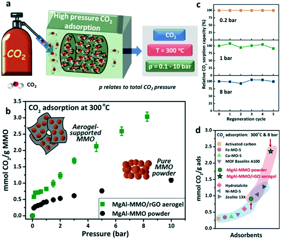 | ||
| Fig. 7 CO2 adsorption by MgAl-MMO/rGO aerogels at high pressure and temperature (a); CO2 adsorption isotherms in a pressure range of 0.2 to 10 bar (b); relative CO2 adsorption capacities at 0.2, 1, and 8 bar CO2 pressure (c); comparison of sorption capacities with other reports (d). “Reproduced from ref. 108 with permission from Wiley-VCH, copyright 2020”. | ||
As discussed earlier, N doping of graphene can enhance the CO2 adsorption due to the chemical interaction of CO2 gas molecules with N doped adsorbents. Highly efficient traditional sorbents are only amine systems, and so the introduction of the conducting polymer polyaniline (PANI) to graphene is of interest because of the presence of primary and secondary amine moieties.29,112
The preliminary investigation on CO2 adsorption using PANI/HEG (hydrogen exfoliated graphene) was reported by Mishra et al., and they have achieved adsorption capacities of 75, 47 and 31 mmol g−1 at 11 bar pressure and at 25, 50 and 100 °C, respectively. The physical and chemical adsorptions of CO2 were evidenced by FTIR spectroscopy. The PANI/HEG sorbent showed good cyclability; the capacity of the reused sorbents was only 2–3% lower than that of the fresh sorbent.82 Later, physicochemical adsorption of CO2 on the Fe3O4/HEG hybrid was reported by the same group.28 Similar to their previous results, CO2 adsorption capacities of 60, 35, and 24 mmol g−1 were observed at 11 bar pressure and at 25, 50, and 100 °C, respectively, and the physicochemical adsorption of CO2 on the solid adsorbent was identified using FTIR spectra. Though the surface area of Fe3O4/HEG (98.2 m2 g−1) is lower when compared to that of HEG (443 m2 g−1), the enhanced CO2 adsorption in Fe3O4/HEG was attributed to the chemical interaction between Fe3O4 and CO2, as evidenced from FTIR analysis. Later, research on the CO2 adsorption ability of graphene oxide (GO) hybridized with Fe3O4 and PANI was carried out and it showed an increment in adsorption capacity of GO from 0.25 mmol g−1 to 2.3 mmol g−1 by the incorporation of Fe3O4 and then to 3.2 mmol g−1 after the introduction of PANI to the binary system of Fe3O4 and GO. The improved CO2 adsorption capacity of the ternary system is mainly attributed to the increased porosity and micropore volume of graphene oxide due to the functionalization with Fe3O4 and PANI. The low adsorption energy of the hybrid hints at the physisorption of CO2 (ref. 29), while chemisorption of CO2 on the adsorbent was not evidenced through their study. Similar to PANI, polypyrrole (PPy) was also introduced to graphene for CO2 adsorption. N-Doped porous carbon obtained via chemical activation of PPy/graphene composites using potassium hydroxide solution is reported in a study. The chemical activation led to the N-doping of porous carbon in PPy, while the graphene units remain intact. PPy/graphene adsorbents with different weight percentages of GO were synthesised by in situ chemical polymerisation of pyrrole in the presence of GO using ammonium persulphate as an oxidant and the subsequent reduction of GO hybrids with hydrazine yielded PPy/graphene hybrids. The chemical activation using KOH solution was carried out at different temperatures (400, 500, 600, and 700 °C). The maximum CO2 adsorption capacity of 4.3 mmol g−1 was observed for the adsorbents activated around 600 °C, and this is due to the formation of microporous structures with a pore size of 1.72 nm, which in turn can lead to a better adsorption and adsorbate–adsorbent interaction.113 In a similar study, a chemically activated porous PPy/rGO was reported. Potassium citrate was used as an activation agent at 700 °C and the porous PPy/rGO material with a BET surface area of 1650 m2 g−1 and 92% microporosity showed an adsorption capacity of 6.8 mmol g−1 at 0 °C and 760 mm Hg.30
3.2 Transition metal dichalcogenides
Transition metal dichalcogenides (TMDCs) are semiconductors of the type MX2, where M is the transition metal atom such as Mo or W and X is a chalcogenide atom like S, Se or Te. TMDCs are a promising alternative to graphene because of their direct bandgap, robustness, and atomic level thickness with 2D characteristics.114 Recently, various strategies are adopted for the synthesis of TMDs such as plasma-assisted synthesis,115 mechanical exfoliation,116 ion intercalation assisted liquid exfoliation,117 wet chemical synthesis, chemical vapor deposition (CVD),118etc. Among TMDCs, MoS2 has been widely used in various environmental applications such as gas adsorption and subsequent reduction to valuable chemicals. The initial attempt on CO2 capture based on a 2D MoS2 membrane was carried out by Shen et al. and they have reported MoS2 incorporating Pebax polymer mixed matrix membranes with good CO2 permeability and selectivity. MoS2 with stronger adsorption energy for CO2 (205 meV) than N2 (137meV) easily got adsorbed. The diffusion or permeation through the membrane occurs because of the dissolution of the adsorbed gas in the membrane.119 In a similar way, studies on a defect-free Pebax-MoS2 membrane obtained by solution casting with different amounts of MoS2 loading from 0 wt% to 5.66 wt% were explored. The highest CO2 permeability of 67.05 Barrer and CO2/N2 selectivity of 90.61 were observed for the 4.67 wt% MoS2 incorporating Pebax membrane. Further, the molecular simulation studies proved that the CO2 solubility and selectivity of the mixed matrix membrane were significantly improved after the addition of MoS2 due to its high affinity towards CO2.120 Later, the influence of the electric field on the adsorption behaviour of CO2 on the MoS2 monolayer was analysed121 by carrying out a systematic investigation using DFT calculations on various parameters such as interactions of CO2 with MoS2 in the absence/presence of an electric field, reaction mechanisms of adsorption, optimization of electric fields for CO2 capture and finally a comparison with N2 adsorption by the adsorbent. The DFT calculation showed that an electric field can alter the interaction levels between the adsorbate and adsorbent. For instance, by applying of an electric field of 0.004 a.u., CO2 showed strong interaction with MoS2. However, this interaction was least in the absence of an electric field and this was evidenced by the easy release of CO2 once the electric field was turned off. In contrast, the presence or absence of an electric field did not affect the capture of N2, and this indicates that MoS2 can act as a selective adsorbent for CO2, especially in the presence of an electric field during the post-combustion process where CO2 and N2 are the major components of the combustion gas.121 In another study, Cu nanoparticle incorporating MoS2 for CO2 adsorption and catalytic reduction reactions was analysed. The hybrid made at a particular concentration of Cu and MoS2 (Cu/MoS2-1) showed better adsorption performance (0.44 cm3 g−1) than other hybrids [Cu/MoS2-2 (0.41 cm3 g−1), Cu/MoS2-3 (0.27 cm3 g−1)] and bare MoS2 (0.22 cm3 g−1). The enhanced CO2 adsorption in the hybrids was explained by the additional adsorption of CO2 molecules on the surface of Cu nanoparticles.122 Further, a theoretical approach for the CO2 adsorption on the MoS2 monolayer was made and the DFT calculations reveal the different occupancies of CO2 molecules on the 2D monolayer surface with low energy cost (ΔE = −57.9 ± 2.5 kJ mol−1) and this points to the adsorbate's physisorption on the adsorbent. The interaction energies calculated for MoS2 were larger when compared to graphene, which hints at the suitability of MoS2 nanosheets over graphene for greenhouse gas adsorption applications. Also, from simulation studies, they have inferred that the adsorption process is controlled by van der Waals interactions where CO2 molecules were arranged parallel to the monolayers of the MoS2 surface.76 Cho et al. have compared the NO2 gas adsorption on MoS2 which is aligned in three different ways such as horizontally aligned MoS2 with an exposed basal plane, vertically aligned MoS2 with exposed edges and a mixture of horizontally & vertically aligned MoS2 layers (exposed basal plane and edges) synthesized using a CVD process. They reported that gas adsorption is highly dependent on the alignment of MoS2 layers, and a significantly higher gas adsorption was observed in edge sites of vertically aligned MoS2 compared to MoS2 with an exposed basal plane. The experimental results were well correlated with DFT calculations, where strong NO2 binding energies near the edge sites of MoS2 were observed.123 Based on these results, researchers had concluded that the presence of S-vacancies or defects on the MoS2 surface is desirable for the adsorption of non-polar gases. Also, they stated the importance of tuning the surface of the adsorbent to obtain reactive edge sites on MoS2 flakes to target a specific gas of interest.73 For this, they have investigated the effect of nitrogen doping on defective and non-defective MoS2 surfaces for CO2 adsorption properties. MoS2 with 1S vacancy and MoS2 with ternary N doped 1Mo vacancy samples showed strong CO2 binding energies (0.908 eV and 1.818 eV) and this reveals that the defective and N doped MoS2 can have enhanced CO2 adsorption due to the covalent and electrostatic interactions with the gas molecule. Conversely, the defect-free MoS2 showed weak van der Waals interactions with CO2 leading to poor adsorption characteristics. Moreover, the selective adsorption of CO2 over N2 was identified for the defective and N-doped MoS2, and so the importance of heteroatom-doping and defects in the structure of MoS2 for the enhanced molecular adsorption of CO2 was pointed out.73 A theoretical investigation of the gas adsorption behaviour on MoSe2 was examined using DFT calculations. The results indicated the poor adsorption of CO2 and CO gases by MoSe2 monolayers, whereas the material was found to be more sensitive towards the adsorption of NO2 and NO. The high selectivity of MoSe2 towards NO2 and NO was attributed to the distinct charge transfer between the adsorbate and adsorbent124 and this indicates the inability of MoSe2 for CO2 adsorption applications.3.3 Hexagonal boron nitride
Hexagonal boron nitride (h-BN) nanosheets are 2D structures and have excellent electrical, thermal, and optical properties with broad applications. A few layered h-BN synthesised from boric acid and urea through a chemical route with a high surface area (927 m2 g−1) was found beneficial for CO2 capture applications.125 Porous and few layered h-BN nanosheet adsorbents from MgB2 and NH4Cl with a good micropore volume showed a CO2 adsorption of ∼10 cc g−1 with a CO2/N2 selectivity of 26.3.126 The BN adsorbent with a surface area of 235 m2 g−1 showed the maximum CO2 adsorption at 760 Torr at 298 K. Marchesini et al. have investigated the CO2 adsorption capacity of BN synthesized by using single and multiple N precursors. For instance, BN synthesized using urea showed a microsponge-like structure with the existence of nanometre ranging mesopores, whereas BN synthesized using urea and melamine showed the presence of a crumbled nanosheet with inhomogeneous small mesopores. The scanning transmission electron microscopy (STEM) tomography images of the BN samples are shown in Fig. 8. The high surface area (1900 m2 g−1) BN sample prepared by using multiple N precursors showed a CO2 adsorption of 1.6 mmol g−1 at 1 bar, 25 °C and 8.3 mmol g−1 at 20 bar, 25 °C. They have also evaluated the CO2 sorption capacity of pelletized and non-pelletized BN samples and it was about 1.1 mmol g−1 and 1.6 mmol g−1, respectively, at 1 bar and 25 °C.31 Further, the effect of C doping on BN sheets was demonstrated by the preparation of a novel C-doped BN with significant CO2 adsorption properties. A CO2 uptake of ∼2.9 mmol g−1 was observed for BN while C-doped BN showed an adsorption of ∼5.5 mmol g−1 at 273 K and 1 bar.32 The effect of charge on the BN nanomaterial on CO2 adsorption was investigated by DFT calculations. BN with a negative charge showed strong interaction with CO2 while spontaneous desorption of CO2 from the BN surface was evidenced once the electrons were removed from the system. The charged BN showed high selectivity for CO2 capture from a gas mixture containing CO2/CH4/H2.81 Similarly, the effect of an electric field on CO2 adsorption and selectivity was analysed using DFT calculations. The application of a vertical electric field increases the binding energy of CO2 on h-BN sheets and it was inferred that the h-BN is a suitable candidate for CO2 adsorption from the gas mixture containing H2, CH4, N2, CO, and H2O, especially in the presence of an electric field.80 In a study, the incorporation of the BN nanomaterial in PVA, and subsequent foam formation by freeze drying for CO2 adsorption was demonstrated. The high gas adsorption of 340% was ascribed to N functional groups and high surface area associated with the BN-PVA foam.78 In another study, the interactions between the gas and the adsorbent surface and the mechanism of CO2 adsorption on h-BN nanosheets were analysed using DFT and MD calculations.77 The report claims the physisorption of CO2 gas molecules on h-BN nanosheets. The significance of tuning and functionalising the pores of the adsorbent to improve the CO2 adsorption is highlighted in their study. | ||
| Fig. 8 STEM images of BN synthesized using urea (BN-U5) (a) and BN synthesized using urea and melamine (BN-MU1:5) (d); 3D tomography of BN-U5 (b) and BN-MU1:5 (e); 3D reconstruction of pores of BN-U5 (c) and BN-MU1:5 (f). “Reproduced from ref. 31 with permission from American Chemical Society, copyright 2017”. | ||
3.4 MXenes
MXenes are another class of 2D materials that have received significant attention beyond graphene, TMDCs, and h-BN. They are early transition metal carbides and carbon nitrides such as Ti2AlC, Ti3AlC2, Ti3C2, Ti2C, Nb2C, V2C, Ti3CN, etc. with metallic conductivity and strong ionic, covalent and metallic bonds.127 The general formula for MXene is Mn+1XnTx (n = 1, 2, 3), where M is the early transition metal, X is carbon or nitrogen, and T represents terminal functional groups. MXenes are produced by selective etching of group III A or IV A elements using hydrofluoric acid. Due to the toxic nature of HF, other environmentally friendly methods adopted are alkali treatment,128 electrochemical etching,129 Lewis acid etching,130etc. The CO2 uptake by 2D MXene carbides (M2N) was analysed by DFT calculations, and a gas loading capacity of ∼2.3 to 7.96 mol kg−1 at low CO2 partial pressure and high temperature was achieved and this hints at its practical utility for CO2 adsorption directly from the atmosphere.33 The relation between the microstructure of carbide MXenes (Ti3C2Tx, V2CTx) and the CO2 adsorption properties was analysed.34 DMSO intercalated Ti3C2Tx with a surface area of 66 m2 g−1 and high volume capacity of 502 Vv−1 showed a CO2 adsorption capacity of 5.79 mmol g−1 at 298 K and 0–4 MPa. Similarly, the effect of the thickness of carbide MXenes was analysed by DFT calculations, and the results confirmed the efficiency of these materials for CO2 capture with a minor influence from the thickness of the material. Also, the surface of different carbide MXenes (Mn+Cn: n = 1 to 3, M = Ti, Zr, Hf, V, Nb, Ta, Mo, and W) was analysed and the largest adsorption energy was observed for the system with a d2 electronic configuration and then for d3 and d4 systems.82 A similar type of DFT calculation on CO2 adsorption and conversion based on M2C type MXene was carried out and the results indicate that the presence of a surface lone pair of electrons is the driving force for the adsorbate–adsorbent interactions.131 In another study, the adsorption/desorption rate of CO2 on 2D M2N materials (M = Ti, Zr, Hf, V, Nb, Ta, Cr, Mo, W) was analysed using DFT calculations. The study evidenced the existence of adsorbed anionic CO2δ− species with significant MXene to CO2 charge transfer. The considerable adsorption energy (−3.13 eV) makes M2N more suitable than M2C for efficient CO2 capture and storage. Due to the high electronegativity N layer, M2N can withdraw a higher charge density from the metal than the C layer in M2C, and this implies a reduction in the charge transfer from the metallic layer of MXene to CO2 in M2C type MXene.132 In a study, effective adsorption of CO2 gas (≈12 mol kg−1) on individual sheets of 2D Ti3C2Tx carbides was reported.133 Recently, the CO2 separation capacity of the Ti3C2Tx incorporating Pebax mixed matrix membrane was compared with a GO filled membrane. Around 20 wt% of Ti3C2Tx was able to disperse in the matrix due to the good level of interfacial interactions arising from the presence of polar groups present in MXene. In contrast, only 5 wt% of GO was able to be incorporated in the Pebax matrix. The high level loading of MXenes was found to be beneficial especially under humid reaction conditions, but it was not promising under dry conditions.1343.5 Carbon nitride
Graphitic carbon nitride (g-C3N4) has received tremendous attention because of its excellent properties and similarities with 2D graphene and it consists of hexagonally organized heptazine (tri-s-triazine) units linked through tertiary amines. The conventional exfoliation of carbon nitride is of less interest because of the tightly packed heptazine units.135 However, the synthesis of g-C3N4 through the direct pyrolysis of N-rich precursors like urea makes it more approachable.85 Since the nitrogen species in g-C3N4 is of low alkalinity, the interaction between g-C3N4 and CO2 is weak, and the use of pristine g-C3N4 for CO2 adsorption application is limited. However, amine functionalization via chemical grafting or physical impregnation can lead to more adsorbent–adsorbate interactions. For instance, the physical impregnation of polyethyleneimine (PEI) with g-C3N4 was analysed for CO2 adsorption applications. A CO2 adsorption capacity of 3.77 mmol g−1 was observed for PEI-C3N4 composites at 100 °C and ambient pressure, which was superior to pristine g-C3N4. The study inferred that the presence of amine groups on the composite surface, not the surface area, plays a major role in deciding the CO2 adsorption capacity.85 Reduced graphene oxide aerogel was reported as a template platform for the growth of porous carbon nitride with a good surface area for CO2 adsorption applications. The gelation of the carbon nitride precursor (dicyandiamide) incorporating graphene oxide solution, and the subsequent solvent exchange, liquid extraction and thermal treatment resulted in the formation of carbon nitride–graphene oxide aerogels. The schematic of the synthesis of carbon nitride aerogels for selective CO2 capture is shown in Fig. 9. A CO2 adsorption capacity of 0.43 mmol g−1 at 0.1 bar and 300 K was observed for these aerogels with excellent regeneration capability (R = 97.6%) and high CO2 selectivity.135 In another study, a high-pressure investigation of ionic functionalized graphitic carbon nitride for CO2 adsorption was analysed. CO2 adsorption of g-C3N4 nanosheets functionalized with an ionic liquid (1-butyl-3-methylimidazolium bis(trifluoromethyl sulfonyl)imide ([BMIM][TFSI])) was analysed at 15 bar pressure and 25 °C showing a sorption capacity of 42.93 mmol g−1 which was higher as compared to g-C3N4 nanosheets (19.78 mmol g−1) and bulk g-C3N4 (8.54 mmol g−1). Due to the combined effects of physisorption and chemisorption, an enhanced interaction between CO2 and ([BMIM][TFSI]) functionalized g-C3N4 nanosheets was achieved and this led to a high CO2 uptake.35 The non-noble metal single-atom catalysts of Fe, Co, Ni and Cu supported on g-C3N4 were recently explored for CO2 adsorption. DFT calculations revealed that the CO2 adsorption energies of Fe-g-C3N4, Co-g-C3N4, Ni-g-C3N4, and Cu-g-C3N4 were −0.40, −0.16, −0.21, and −0.17 eV, respectively.136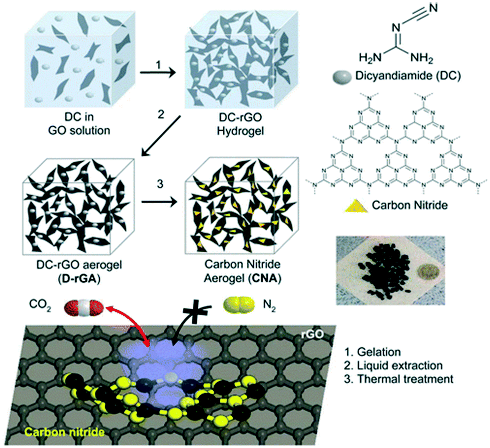 | ||
| Fig. 9 The preparation of carbon nitride aerogels for the selective adsorption of CO2 over N2. “Reproduced from ref. 135 with permission from American Chemical Society, copyright 2015”. | ||
3.6 Other 2D materials
MOFs and COFs have been reported for gas adsorption applications. An ultrathin mixed matrix membrane containing a 2D MOF was prepared, and the addition of lamellar 2D copper 1,4-benzenedicarboxylate (MOF) nanosheets led to the formation of dense membranes with good CO2 selectivity (15.6), and high CO2 permeance (407 GPU) was reported.137 MOFs are linked by unstable coordination bonds, particularly under heat and humid conditions, and this structural instability is a significant problem, especially for CO2 capture in pre or post-combustion processes. However, COFs are linked by covalent bonds and are structurally stable to use under drastic conditions of CO2 capture. Further, the introduction of N functionalities and the pore size tuning of COFs make them interesting for gas adsorption applications.138 2D COFs are mainly used in the preparation of membranes for the capture and separation of CO2 gas.137–140 Water-soluble COFs with 2D characteristics and porosity were prepared and blended with commercial polymers to form mixed matrix membranes (MMMs). The defect-free and mechanically stable COF incorporating MMMs showed better selectivity and gas permeability when compared to the pristine polymer membrane.140 In another work, DFT and MD calculations under thermodynamic conditions of a post combustion process were applied on a diamine linked 2D COF membrane for CO2 gas adsorption. The results hint at the physisorption and better selectivity for CO2 gas molecules over N2 by the 2D COF.138 An ultrathin membrane was fabricated in a recent study by layering two intrinsically charged ionic covalent organic nanosheets. The layered ultrathin hybrid membrane showed better gas separation properties compared to their counterparts. The overall H2/CO2 separation performance was excellent compared to literature results.141 Recently, a 2D COF and 3D MOF dual layered membrane was reported for H2/CO2 separation. A 3D MOF film with vertical binding sites to accommodate a 2D COF producing a 2D COF composite membrane with superior H2/CO2 selectivity (32.9) and high permeability was reported.139Borophene is a new type of 2D material and it is a single-layered boron-based material with all four different phases being metallic.142 DFT calculations demonstrated the utility of conductive borophene nanosheets for gas adsorption applications. The binding strength of CO2 molecules on the adsorbent can be enhanced by introducing an extra electron to it, which leads to a CO2 capture capacity of up to 6.73 × 1014 cm−2.143 Later, the gas (CO, NO, CO2, NO2, H2S, and NH3) adsorption properties of borophene were analysed relative to the adsorption energies. The negative values of adsorption energy indicated the strong adsorption characteristics of the gases on the adsorbent. Further, the introduction of a transition metal into borophene reduced the adsorption energy, and this indicates the advantages of transition metal doping on borophene for enhanced CO2 adsorption.144 The adsorption of gas molecules (CO, CO2, NH3, NO, NO2 and CH4) on borophene was analysed by DFT calculations, and the studies revealed the chemisorption of all gases except CH4 on borophene.145
Another new type of 2D nanomaterial is green phosphorus and its monolayer variant green phosphorene. The CO2 adsorption properties of the phosphorene slit pores were studied using DFT and GCMC calculations, and the adsorption of natural gas was analysed at 300 K and pressure up to 3 MPa. The simulation results indicate the better selectivity for CO2 over CH4 in a binary mixture of CO2/CH4 with an enhanced adsorbate–adsorbent interaction, especially at a high mole ratio of CO2 in the gas phase.84 Recently, the strong adsorption of NO, NO2, CO, and CO2 gases on green phosphorene was analysed using theoretical calculations.146 Another 2D material included in the C family is graphyne, which is one atom thick and consists of sp and sp2 carbon atoms. Very recently, first row transition metal doped graphynes for enhanced CO2 adsorption with good selectivity using grand canonical Monte Carlo (GCMC) and DFT techniques were investigated by researchers. The transition metals (TM) like Cu, Co, Fe and Mn were selected for doping with graphyne and the most stable Cu doped graphyne (Cu-GY) exhibited a high CO2 uptake of 8.46 mmol g−1 at 298 K and 1 bar. The enhanced stability of Cu-GY is due to the high cohesion and formation energies, and the Cu-GY adsorbent showed good selectivity for CO2 over methane (∼330.61), nitrogen (∼912.68), and hydrogen (∼2640.94) gases. The high CO2 adsorption capacity and selectivity of Cu-GY are due to its high isosteric heat (40 kJ mol−1), which was higher than other TM-GY adsorbents. The 2D density of different gases on the TM-GY adsorbent was analysed using Monte Carlo configurations at 298 K and 1 bar (Fig. 10). The green areas in the plot represent the high density of gases while the blue area shows the low density of gases. Fig. 10 shows the CO2 adsorption abilities of TM-GY with low H2 adsorbing properties. The strong interaction of gas molecules with metal doped graphyne and the multilayer adsorption on the adsorbent make graphyne a promising material for CO2 separation and capture applications.147
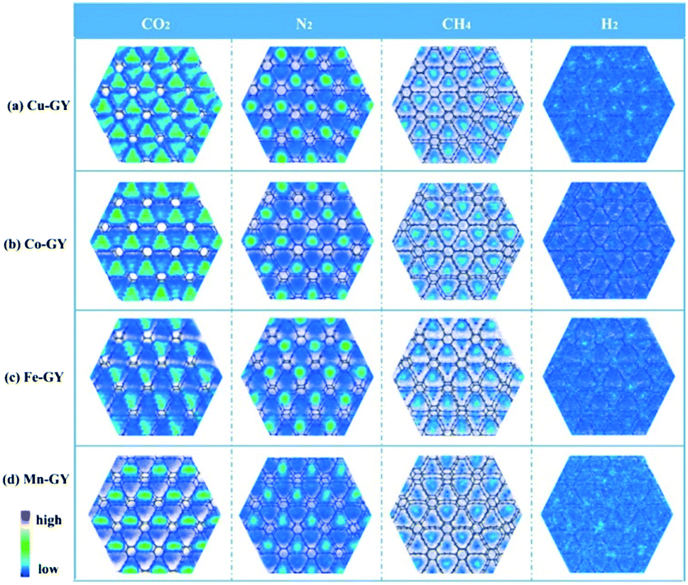 | ||
| Fig. 10 CO2, N2 CH4 and H2 gas distributions on TM-GY. “Reproduced from ref. 147 with permission from Elsevier, copyright 2021”. | ||
Nanoclays are another class of 2D materials of layered mineral silicate with a few nanometer thickness and exceptionally high mechanical properties. Since they are based on a mineral, nanoclays are one of the most economical and abundant solid adsorbents used for pollutant removal. Montmorillonite (MMT) clay is widely used, and it is under the smectite group. Layers of MMT contain an octahedral sheet with an Al cation sandwiched by two tetrahedral sheets with the main silicon cation.148 The major drawback of clay-based materials for CO2 adsorption is their low efficiency CO2 uptake under moist conditions and this was due to the diffused water molecules that prevent the capture of gas molecules. In the absence of water molecules (dry conditions), one can expect high CO2 uptake due to nano-channels in the clay for the intercalation of CO2 molecules. An analysis of variance (ANOVA) study was carried out to predict the major process variable on CO2 adsorption. The results indicated the importance of temperature and pressure on the adsorption process. Under optimum conditions of temperature and pressure of 25 °C and 9 bar, a CO2 adsorption of 100.67 mg g−1 was achieved and a good agreement between theoretical and predicted (104 mg g−1) values of gas adsorption was observed.148 Like the above-mentioned study, an ANOVA treatment was tried on NaOH modified MMT by the same research group. Under optimum conditions of temperature (65 °C), pressure (1 bar), acid concentration (5.99 M) and wt% NaOH (39.76%), a CO2 adsorption of 105.55 mg g−1 was observed with a desirability index of 0.996, which reveals the good correlation between experimental and predicted gas adsorption values.149 In another study, the effect of surface modification of MMT with polyphosphoric acid and hybridization with rGO for CO2 adsorption at 25 °C and 1 bar was analysed and the modified MMT/rGO hybrid showed a CO2 adsorption of ∼0.5 mmol g−1 at low pressure.150 Another method to improve the gas adsorption properties of pristine MMT is the functionalization or grafting nitrogen functionalities to MMT. Therefore, octadecylamine modified MMT was prepared, and showed a CO2 uptake of 7.16 mmol g−1 at room temperature and high pressure of 50 bar while the pristine MMT showed only 3.47 mmol g−1 under similar conditions.36
To summarize, a greater amount of CO2 adsorption was evidenced by nitrogen doping or by introducing nitrogen functionalities in the system and this is due to the chemisorption of the CO2 adsorbate on the solid adsorbents. The chemisorption of CO2 on N doped adsorbents was explained through the Lewis acid–base interactions, in which CO2 is a weak Lewis acid due to the presence of electron deficient C and negatively charged nitrogen sites act as Lewis bases. Further, in N-doped systems, the interactions between EQM of the CO2 molecule and local polarization in nitrogen-doped adsorbents enhance the CO2 adsorption energy, leading to selective and higher CO2 adsorption from the flue gases.6 However, in amine functionalized adsorbents, surfaces exhibit a different type of interaction with CO2 molecules. The primary, secondary or tertiary amine functionalized adsorbents interact with CO2via the formation of the zwitterion intermediate to form carbamates. In the absence of water, which is an additional free base required for the formation carbamate from the intermediate, another mole of amine is utilized. Thus, in the absence of water molecules, two moles of amine are required to capture one mole of CO2.151 Nonetheless, due to reduced thermal stability of amine functionalised adsorbents, N doped adsorbents are preferred for CO2 capture. On the other hand, during physical adsorption, along with the van der Waals attraction of CO2 and the adsorbent, EQM–electric field gradient interactions are also taking place. The value of EQM is the main factor deciding the selectivity for gases and therefore, carbon dioxide molecules with a high EQM value will be attracted and adsorbed on the solid surface when compared to low EQM N2 gas. Fig. 11 represents the possible types of interactions taking place during the adsorption of CO2 on the adsorbent. Another strategy to improve the adsorption capacity is developing porous adsorbents with an adequate surface area and varied morphology. Therefore, we can conclude that high surface area adsorbents with N doping could deliver enhanced CO2 adsorption characteristics. The CO2 adsorption capacities of various 2D nanomaterials and their hybrids are summarized in Table 2. It showed that high adsorption capacities have been achieved for 2D nanomaterials by implementing high CO2 pressure (10 to 30 bars) which hints at their utility for CO2 capture during post and pre-combustion capture processes. However, the developments of 2D nanomaterial-based adsorbents which can adsorb an adequate amount of CO2 from the atmosphere make them more attractive due to the possibility of direct removal of CO2 from the atmosphere. From the data described in Table 2, we can infer that N-doped porous or aerogel materials based on graphene or MXenes are expected to have future advances in low-pressure CO2 adsorption applications.
 | ||
| Fig. 11 Interaction between CO2 and the adsorbent during physical and chemical adsorption. | ||
| Adsorbent | BET surface area (m2 g−1) | Operating conditions | Type of adsorption | Adsorption capacity (mmol g−1) | Ref. | |
|---|---|---|---|---|---|---|
| Pressure (bar) | Temperature (°C) | |||||
| Graphene | 42.87 | 11 | 25 | Physisorption | 21.6 | 26 |
| Borane modified rGO | 514 | 1 | 25 | Physisorption | 1.81 | 103 |
| rGO/N-doped porous carbon composite | 865.1 | 5 | 25 | Chemisorption and physisorption | 5.77 | 27 |
| MgAl MMO/rGO | 96.8 | 8 | 300 | — | 2.36 | 108 |
| N-Rich graphene based semi-coke-like material | 701.53 | 30 | 25 | Physisorption | 7.11 | 109 |
| B and N co-doped graphene aerogels (BN-GA) | 169.9 | 1 | 0 | — | 2.1–2.9 | 111 |
| PANI decorated graphene | — | 11 | 25 | Chemisorption and physisorption | 75 | 82 |
| Fe3O4/graphene | 98.2 | 11 | 25 | Chemisorption and physisorption | 60 | 28 |
| PANI/GO | 5 | 20 | 27 | Physisorption | 3.2 | 29 |
| PPy/rGO | 1650 | 1 | 0 | — | 6.8 | 30 |
| N-Doped MoS2 | — | — | Chemisorption and physisorption | — | 73 | |
| Porous BN | 1900 | 1–20 | 25 | Chemisorption and physisorption | 1.68.3 | 31 |
| C doped BN | — | 1 | 0 | Physisorption | ∼5.5 | 32 |
| MXene, M2N | — | 1 | 727 | Physisorption | 7.96 | 33 |
| Ti3C2Tx | 66 | 4 | 25 | Physisorption | 5.79 | 34 |
| Polyethyleneimine/g-C3N4 | 1.2 | 1 | 100 | Physisorption | 3.77 | 85 |
| C3N4 functionalized porous rGO aerogel | 450 | 0.1 | 27 | Physisorption | 0.43 | 135 |
| g-C3N4 nanosheets functionalized with ionic liquid | 182.9 | 15 | 25 | Chemisorption and physisorption | 42.93 | 35 |
| Cu doped graphyne | — | 1 | 25 | Chemisorption | 8.46 | 147 |
| Polyphosphoric acid modified MMT/rGO hybrid | 50.77 | 1 | 25 | Physisorption | 0.5 | 150 |
| Octadecylamine modified MMT | 11.82 | 50 | 25 | Chemisorption | 7.16 | 36 |
3.7 Impact of defect engineering on CO2 adsorption
Structural disorders or defects are vital features that can affect the physical and chemical properties of solid materials. These defective sites can serve as active points during various chemical and physical reactions. In 2D materials, common defects such as vacancies, dopants, substitution, edges and grain boundaries have been observed, leading to enhanced material properties. Apart from these, defect engineering in 2D nanomaterials can be triggered by plasma, electron beam, ozone, and chemical treatments. Defect engineering can be exploited for increased CO2 gas adsorption capacities of 2D solid adsorbents. For instance, the defect engineering of sp2 carbon of graphitic structures of graphene was analyzed using a van der Waals-corrected DFT calculation for improved CO2 capture and separation. The topological defects on graphene such as vacancies (mono, di), Stone–Wales defects, strained graphene (by compression and tensile forces), and graphene folds were considered for the evaluation of the binding energy of gases (CO2 and CH4). Their study reveals that the concave sites in rippled graphene geometries and SW defect sites can enhance the sorption/binding properties.152 In another study, DFT calculations of CO2 adsorption on a defected graphene sheet hint at the physisorption of the gas molecule on the top of the vacancy. Later, the surrounding vacancy can lead to lactone formation and subsequent chemisorption of CO2. The model suggested a reaction pathway that ends up in the desorption of O2 with a minimum energy penalty.153 The defect engineering of MoS2 for better CO2 gas adsorption was analyzed using DFT calculations. The results highlighted the importance of Mo, S vacancies, and N doping for improved CO2 gas adsorption compared to defect-free MoS2. According to their study, MoS2 with one sulfur-vacancy and tertiary nitrogen-doped one Mo-vacancy led to enhanced gas adsorption.73 Similarly, the gas adsorption properties of MOFs can be improved by defect engineering by influencing the factors such as the density of co-coordinatively unsaturated sites, pore size, and specific surface area. As an example, mesopores can be created with vacancy defects, or one can make a porous coordination network compound from a dense coordination network system through defect engineering.154 The CO2 adsorption and sensing properties of a pristine and defected black phosphorene were analyzed using DFT calculations. A significant change in the bandgap was observed after vacancy doping, and the initial CO2 sensitivity was markedly improved by a factor of 50 upon the defect engineering of black phosphorene.155 In a study, defect engineering of a 2D ferromagnet, Fe3GeTe2, was carried out using DFT calculations to suggest an adsorbent with enhanced gas adsorption properties. The Te-deficient Fe3GeTe2 monolayer can adsorb CO2 and H2O covalently on the surface of the adsorbent. However, physisorption of gases was observed with the defect-free ferromagnet. Also, the estimated adsorption ability of defected Fe3GeTe2 was higher than MoS2 and MXenes.156 Even though there are a few reports on the theoretical aspects of defect engineering in 2D materials for enhanced CO2 adsorption, research focusing on experimentation in this area should be well explored for future developments.4. Catalytic conversion of CO2
The conversion of CO2 to valuable chemical feedstocks is of paramount importance to the chemical industries.25 Many of the existing technologies for converting CO2 to value-added products are not cost-effective. So, the research community is keen to identify catalytic materials able to perform CO2 reduction with lower energy input. Among the various materials currently researched, 2D materials are of particular interest because of their high selectivity and mild reaction conditions.7,11,157,1584.1 Thermodynamics and kinetics of CO2 reduction
The CO2 molecule has a low electron affinity, and its transformation is a thermodynamically uphill process.159 The CO2 transformation occurs by a nucleophilic attack at the carbon atom, and CO bond dissociation requires a relatively high energy of 750 kJ mol−1.11 A single electron transfer to the CO2 molecule to generate the CO2˙− radical is considered the first step in the CO2 reduction mechanism.| CO2 + e− → CO2˙− (−1.9 V vs. NHE at pH = 0) |
Another mechanism for CO2 reduction involves the multiple proton-coupled electron transfer (PCET) processes.162,163 PCET is necessary to avoid the activation barriers and excludes the formation of unstable intermediates.164 As the name suggests, the PCET mechanism kinetically relies on the concentration of protons available in the system. CO2 reduction to methanol and methane requires the transfer of six and eight protons, respectively.165,166 As the number of protons and electrons involved in the PCET reaction increases, it escalates the complexity of the reaction.161 Therefore, various reports of CO2 conversion to valuable products like methanol and methane reveal drawbacks such as poor selectivity and low conversion efficiency.167,168 The hydrogen evolution reaction (HER) from water is kinetically more favourable than CO2 reduction. Consequently, proton reduction competes with CO2 reduction and decreases the efficiency of CO2 transformation.169 The readers are redirected to previous reviews for a detailed understanding of the thermodynamic and kinetic aspects of CO2 reduction reactions.161,170
4.2 Structure function relationship in CO2 reduction catalysts
Correlating the structural features of the 2D catalyst with the catalytic performance is an exciting area to be explored. An in-depth analysis of the specific structural features and understanding their role in the catalytic mechanism help researchers in modulating the catalyst for obtaining the desired products. Fine-tuning the oxygen vacancies and single atoms present on the catalytic surface can help achieve the selectivity to the product.171,172In a recent study, Bi2O3 nanosheets with oxygen vacancies were demonstrated to fix CO2 to dimethyl carbonate.172 The oxygen vacancies present on the atomic layers decreased the adsorption energy of CO2 on the surface and enhanced the generation of the CO2˙− radical by a single-electron transfer. The difference in the charge density observed between non-defective Bi2O3 nanosheets and oxygen defective Bi2O3 nanosheets provided insights into the possibility of electron localisation around the oxygen vacancies. DFT calculations arrived at a negative adsorption energy of −0.30 eV for the CO2 adsorbed on oxygen defective Bi2O3 nanosheets (Fig. 12). On the contrary CO2 chemisorption was not observed on the non-defective Bi2O3 nanosheets owing to their weak interaction with CO2. In a similar study, atomic layers of SnS2 with varying oxidation degrees were synthesized to understand the correlation of oxidized sulfides and their efficiency for CO2 to CO conversion.173 DFT calculations concluded that electron localization occurring at the oxidized domains of SnS2 was stabilizing the COOH* intermediate formation resulting in a decreased CO2 activation energy. The mildly oxidized SnS2 layers were reported to have a CO2 to CO conversion rate 2.6 times higher than the pristine SnS2 atomic layers.
 | ||
| Fig. 12 Schematic of the DFT studies showing selective adsorption and conversion of CO2 on oxygen defective Bi2O3 nanosheets. “Reproduced from ref. 172 with permission from Nature, copyright 2019”. | ||
In another study, the CO2 to CO conversion performances of Ni-MOFs and Co-MOFs were compared.174 In the presence of 10% diluted CO2, Ni-MOFs showed a 96.8% CO selectivity with a quantum yield of 1.96%. But the CO2 to CO conversion efficiency of Co-MOFs was negligible in the diluted CO2.
Experimental and theoretical investigations demonstrated the specific adsorption affinity of CO2 molecules over the Ni-MOFs and the resulting formation of Ni–CO2 adducts (Fig. 13, schematic representation). The CO2 to CO reduction pathway proceeds through a COOH* intermediate. The DFT calculations revealed the potential energy barrier associated with  to COOH* conversion to be 62.2 kJ mol−1 for the Ni-MOFs (Fig. 13). But the
  to COOH* energy barrier for the Co-MOFs was 30.5 kJ mol−1, suggesting that the COOH* formation is kinetically favorable on the Co-MOFs compared to the Ni-MOFs. DFT studies, along with the experimental findings, concluded that the initial adsorption of CO2 over the Ni-MOFs is the rate-determining step of CO2 to CO conversion, rather than the electron transfer process.
 | ||
| Fig. 13 (a) The potential energy diagram calculated by the DFT studies explaining the energy barriers associated with the conversion of CO2 to CO. (b) Schematic illustration of CO2 reduction over Ni-MOFs. [Ru(bpy)3]2+ acts as a photosensitizer, and triethanolamine (TEOA) is used as a sacrificial electron donor. “Reproduced from ref. 174 with permission from Wiley-VCH, copyright 2018”. | ||
The role of single atoms (palladium and platinum) anchored on g-C3N4 (Pd/g-C3N4 and Pt/g-C3N4) in the CO2 reduction reaction was investigated by DFT calculations.175 Introducing Pd and Pt single atoms on the g-C3N4 surface enhanced the visible light absorption capacity. Here g-C3N4 was the source of hydrogen (H*) via the HER, and the single atoms (Pd and Pt) were the active sites responsible for CO2 reduction. DFT studies concluded that the Pd/g-C3N4 catalyst is efficient in transforming CO2 to HCOOH with a barrier of 0.66 eV, whereas the Pt/g-C3N4 catalyst was suitable for selectively reducing CO2 to CH4 with a barrier of 1.16 eV. In another study, surface alkalinisation of Ti3C2 MXenes was reported to have improved the selectivity for CO2 reduction to CH4.176 Similarly, a ruthenium nanoparticle incorporating layered double hydroxide (LDH) was efficient in reducing CO2 to CH4.177
4.3 Photocatalytic reduction of CO2
The reduction of CO2 to renewable chemicals/fuels in the presence of sunlight and semiconductors is called photocatalytic CO2 reduction (PCCR).178,179 This multistep process is possible under both UV and visible light irradiation, yielding hydrocarbons and alcohols with respect to the distinct potentials exhibited by photocatalysts.180,181 Nevertheless, PCCR is remunerative in the case of economic and environmental terms but inferior in terms of efficiency and selectivity, as the conventional photocatalysts are overwhelmed with the high charge carrier recombination rate and inept reactor design, apart from poor light harvesting ability leading to low yield.182 To ease these shortcomings, among many suggested ameliorating efforts such as bandgap engineering, co-catalyst loading, non-metal doping, and construction of heterojunctions, choosing a low-dimensional photocatalyst should be the fundamental and baseline norm for designing a flawless photocatalyst.The crucial processes involved in PCCR are summarized in Fig. 14.183 At first (1), light radiation with energy higher than the bandgap of the photocatalytic material leads to the generation of electron–hole pairs in the photocatalyst. Then (2), the electrons and holes migrate to the photocatalyst surface. Later the photogenerated electrons reduce the CO2 molecules into valuable products, and the holes convert H2O to O2 (3). The recombination of electron–hole pairs in PCCR reactions takes place (4). The first two steps in photocatalytic CO2 reduction are the same as those of water splitting. The surface interactions that occur on the photocatalyst determine the fate of the reaction: CO2 reduction or proton reduction.
 | ||
| Fig. 14 Schematic of the four different steps involved in the photocatalytic CO2 reduction by a heterogeneous catalyst. (1) Light absorption, (2) migration of charge carriers to the photocatalytic surface, (3) water oxidation and CO2 reduction, and (4) recombination of electrons and holes. Thermodynamic potential values associated with water oxidation and CO2 reduction into CO, CH4 and CH3OH are also reported. | ||
A practical tactic to improve the photocatalytic performance of the GO nanosheets was devised recently by increasing the defect density on the GO surface. When defects are created, more active sites could trap the photo-excited charge carriers and suppress the recombination process, reliable enough to advance without any hole scavengers like water and providing a result three times better than non-irradiated GO.197 This conventional notion conflicting study revealed the role of defect density in the photocatalytic activity. The less defective graphene decorated TiO2 exhibited up to a seven-fold rise in CH4 formation with respect to pristine TiO2. Compared to rGO with higher defect density, graphene facilitates the smooth diffusion of photo-generated electrons to the reactive sites, triggering the electrical mobility following the photo-reduction process.198 The fabrication of Cu2O/rGO composites was conducted by a one-step microwave method, where the CO2 reduction activity of Cu2O spotted to have risen dramatically, apparently six times higher than Cu2O and fifty times higher than the Cu2O/RuOx junction, pinpoints the significance of rGO in the process. Together with the enhanced stability of Cu2O, the proficiency in charge separation and mobility can be ascribed to rGO and its protection function providing an economically viable photoreduction of CO2, which can thus exclude expensive and rare noble metals like Pt, Pd, Au, Ag, etc.199 Generally, CO2 reduction and water splitting are two rival reaction processes that co-occur during the CO2 reduction process in water resulting in poor yield due to the sheer competition for reactive sites. A manipulated rGO nanosheet, which created more individual reactive sites, was explored, effectively separating and distributing the excess excitons generated by quantum-sized photocatalysts. Here, they fabricated a rGO composite of bismuth monoxide quantum dots (rGO-BiO QDs) furnished with an exclusive charge transfer pathway by a typical hydrothermal method. The synergistic effect resulted in the formation of H2 and CH4 yielding up to 102.5 and 21.75 μmol g−1 h−1, respectively, in the absence of any noble metals or sacrificial agent, beating the direct water splitting production rate, to date.200
Unlike graphene, g-C3N4 is a conjugated polymeric visible-light-driven photocatalyst with many hallmark features, including band structure, thermal and chemical stability, etc. In g-C3N4 the conduction band (CB) edge is necessarily negative for CO2 reduction, and it can proceed without any co-catalysts. In a study, g-C3N4 with two different precursors was fabricated with a large surface area mesoporous flake-like structure from urea with enhanced photocatalytic activity compared with the non-porous flaky photocatalyst derived from the melamine precursor. However, the latter exhibited a selective formation of C2H5OH.201 Still, a high recombination rate of the photogenerated charge carriers is an everlasting challenge to an efficient photocatalyst. The progress in the photocatalytic applications of g-C3N4-based semiconductors for CO2 reduction was summarised in which they suggested a few modifications which can bring about a hike in adsorption and charge separation rates such as structural tuning, elemental doping, co-catalyst addition, and so on.202
Doping a non-polar element like carbon quantum dots on g-C3N4 offers many benefits, such as bandgap tapering and electron-withdrawing effects, which facilitate light absorption and separation of charge carriers. The doping activates the photoreduction with advanced reaction kinetics on the non-polar modified surface, presenting six times the yield (CO and CH4) devoid of any detectable H2 relative to the bare g-C3N4 under similar conditions. This is because of the facile adsorption of the non-polar adsorbate on the modified adsorbent.204
Forming heterojunctions with other photocatalysts is a widely applied strategy to encourage charge separation and thus improve the overall catalytic performance. For instance, the MOF-based/g-C3N4 photocatalytic system is a versatile and promising means of promoting photocatalytic efficiency for CO2 reduction owing to its large surface area and unique porous structure.205 In a recent study, the NH2-MIL-101(Fe)/g-C3N4-X (MCN-3) heterosystem bearing coordinated unsaturated metal sites and an amino functional group was developed where a solid–gas interfacial route emerges in between the adsorbate and photocatalyst, which boosts the CO2 adsorption ability besides selectivity, generating CO 6.9 times higher than pristine g-C3N4 under visible light irradiation.203Fig. 15 shows the morphology of bare g-C3N4 with a sheet-like agglomerated architecture. The TEM image (Fig. 15d) exhibits a wrinkled lamellar structure with cured layers composed of pores, whereas NH2-MIL-101(Fe) (Fig. 15b and e) gives an octahedral morphology with a smooth surface. There is not much distinct morphological change that occurs after the formation of heterostructures indicating the uniform dispersion of g-C3N4 particles into the octahedral crystals (Fig. 15c and f).
 | ||
| Fig. 15 SEM and TEM images of (a and d) pristine g-C3N4; (b and e) bare NH2-MIL-101(Fe); (c and f) MCN-3 heterostructure. “Reproduced from ref. 203 with the permission from American Chemical Society, copyright 2020”. | ||
Carving metal oxides such as TiO2, ZnO, Fe2O3, SnO2, and WO3 into thin atomic layers unveils a new arena of hidden exotic properties, including rich reactive sites with a better charge carrier transport and efficient light absorption besides natural resistance to oxidation.206,207 Among these promising 2D materials, ZnO sheets are benign and highly stable, becoming a non-polar graphene-like structure (g-ZnO) when the thickness gets reduced into a few layers in which the electronic structure is immensely dependent on the number of layers. In a study, the concept of steering the quantum confinement effect in the out-of-plane direction by engineering the interlayer coupling and surface activity of ultrathin films was examined to discover the film thickness of materials. In their study, the effect of thickness from the bulk to a monolayer on photocatalytic reduction of CO2 by ZnO was studied through DFT calculations.208 One of the most chemically stable, environmentally sound and highly recognized photocatalysts is TiO2, challenged with limited redox ability and a short light response range that can be tackled by forming vastly recommended heterojunctions. Recently He et al. came up with a Ti3C2 MXene quantum dot decorated 2D/2D TiO2/C3N4 core–shell photocatalyst with a boosted CO2 reduction activity generating CO and CH4 as products with thrice the CO evolution rate compared to its pristine forms. Here, Ti3C2, usually a renowned 2D layered MXene featuring a fascinating work function and reduced activation energy for CO2 reduction, acts as a potent co-catalyst in 0D form, with most of the properties similar to its 2D counterparts.209 Lately, the potential of 2D MXenes as co-catalysts for an efficient photocatalytic CO2 reduction was verified, which has been attributed to their smooth conductivity, rich active sites, and enlarged specific surface area.210
2D metal chalcogenides such as MoS2, WS2, MoSe2, WSe2, SnS2, etc. are versatile materials that can be candidates for photocatalysts and non-noble metal co-catalysts considering their catalytic activity, availability, and affordability. They are generally utilized in H2 production but are now starting to be applied in the field of CO2 photoreduction.179,211,212 The superior photocatalytic activity is claimed by MoS2 nanosheet-covered TiO2 fibers with a narrow bandgap and tuneable conduction band. The proposed material has an excellent photosensitizing effect originating from the presence of MoS2 nanosheets, which generated a better yield of methane and methanol products.213 Correspondingly, a WSe2–graphene–TiO2 ternary system was fabricated via a simple ultrasonic technique and the influence of WSe2 and graphene nanosheets on the bandgap of TiO2 was found, enhancing its photocatalytic performance under UV/Vis light.214 In a similar study, a SnS2/TiO2 based 2D–2D heterojunction photocatalyst was prepared hydrothermally by depositing ultrathin SnS2 nanosheets onto titania nanosheets. The so-formed photocatalyst produced methane with a yield of 23 μmol−1 g−1 h−1, which is 20, 10, and 9 times higher than pristine titania, titania nanosheets, SnS2 nanosheets, respectively, indicating the importance of metal chalcogenides as co-catalysts in photocatalysis.215
A developing category of anionic clays, namely, layered double hydroxides (LDHs), are reliable CO2 reduction photocatalysts with a high sorption capacity for adsorbates between the layered space and flexible catalytic properties with respect to the chosen metal cations.216,217 Amidst quite a few LDHs, Zn–Al LDH reduces CO2 to CO, while Cu-containing LDH promotes an efficient reduction to produce methanol. More incredible performance is evident with the collaboration of another 2D material like g-C3N4. For instance, a heterojunction between NiAl-layered double hydroxide (NiAl-LDH) and g-C3N4 nanosheets was engineered via a simple in situ hydrothermal method.218 The system exhibited the highest CO evolution rate of 8.2 μmol h−1 g−1, which is five times better than pristine g-C3N4 and nine times better than the pure NiAl-LDH without the presence of any sacrificial agents owing to the synergic effect between the two nanosheets. Besides the effective interfacial contact due to the 2D/2D architecture the catalyst showed arrested recombination, prominent charge carrier transport to the surface and CO2 adsorption rate. Recently a study highlighted the capability of LDH-based photocatalysts in the arena of photocatalytic CO2 conversion, projecting their excellent physicochemical and electrical properties. Due to the favourable redox chemistry ascribed to its 2D structure, the LDH material enriched with surface hydroxyl groups providing basicity, better visible-light harvesting ability, and reliable stability, becomes a suitable choice for coupling with other 2D materials for an innovative photocatalysis.194
Besides the photocatalysts mentioned above, a few more developing 2D materials are yet to be explored more for CO2 reduction. For instance, h-BN nanosheets; covalent triazines having better stability, abundant nitrogen content,219 efficient visible light harvesting, and a tuneable bandgap;220 and black phosphorus with a flexible bandgap, high exciton mobility, etc.,221 are examples. Unlike typically used catalysts such as graphene and g-C3N4, hexagonal boron nitride (h-BN), a honeycomb-like 2D material, exhibits ionic properties endorsing directional transfer of electrons to the adsorbate, promoting the active carbon species. An oxygen atom-tailored ultrathin BN nanosheet was engineered to improve the optical absorption and adsorption efficiency of the photocatalyst. Contrary to the normal adsorption process, CO2 is chemisorbed onto the catalyst surface, enabling a continuous electron delivery, CO2 activation, and interfacial interaction which helps to decrease the activation energy of the transformation process. The reported rates of the products (H2 and CO) were 3.3 and 12.5 μmol g−1 h−1, respectively, which can be considered a pioneering work in the rational design of metal-free photocatalysts.196 Likewise, in a recent study, black phosphorus and a covalent triazine framework (CTF) have been devised via self-assembly, which enhanced the selectivity for CO2 reduction to methane over CO. A strong interaction between CO and the catalyst surface prevents the desorption of CO, which helps in the further reduction to methane, and this is a novel strategy for selective and efficient catalysis.222 To conclude, among many challenges, a key obstacle in developing an ideal and efficient photocatalyst is that only a single electron is excited by a photon aside from deficient solar light harvest. It invokes a dire need for attention and action in the coherent architecture of a perfect photocatalyst which can be viewed as the most reliable and economic approach in reducing the globally threatening CO2 and producing green fuels.
4.4 Electrochemical CO2 conversion
The electrochemical process has gained substantial attention in converting CO2 to useful and value-added fuels and commodity chemicals (methane, CO, formic acid, methanol, ethylene, and ethanol) utilising electricity from renewable sources to resolve the energy and environmental problems and to maintain a healthy balance between energy supply and global carbon content. A large amount of activation energy is required for one-electron reduction of CO2 and HER in protic media, which limits the selectivity of the electrochemical CO2 reduction (ECR) process.223,224 In addition, a well-matched equilibrium potential for the formation of CHO, CO, and COOH results in poor selectivity by inhibiting the tuning of the intermediates to the precise product.225 Moreover, the poor solubility of CO2 in aqueous solutions led to low current density. These limitations like poor selectivity,226 high over-potential,227 low current density,228 and poor energy efficiency of ECR limit the industrialisation of the process. | ||
| Fig. 16 Schematic diagram representing the formation of various valuable products via the electrochemical CO2 reduction method. | ||
Some of the key parameters that are used to measure the performance of an electrocatalyst include the (a) overpotential (η), (b) current density, (c) faradaic efficiency, (d) energetic efficiency, (e) turnover frequency and (f) Tafel slope.11 Overpotential is defined as the difference between the thermodynamically determined reduction potential of a reaction and the actual reduction potential value in which the reaction is experimentally observed.233
Faradaic efficiency is defined as

Recently, 2D graphene has gained much attention as a promising candidate for CO2 ECR due to its excellent physical, electronic, and mechanical properties.24,25,251 The studies on graphene-based materials reveal that doping of graphene with heteroatoms like boron, phosphorous, nitrogen, etc. shows better ECR efficiency than pristine graphene. As we already discussed, during the process the selectivity of CO2 ECR over the hydrogen evolution reaction (HER) is a significant concern. In a study the development of porous Zn NPs wrapped with thin rGO layers for selective CO2 ECR over HER was reported. They found that the current density for the CO production of the pristine ZnO catalyst remains unchanged while the current density for the HER process selectivity is suppressed upon the incorporation of rGO layers. The suppression is tuned by varying the amount of rGO in the catalyst and 94% FE is achieved. The decoupling of the HER from CO2 ECR is due to the fast proton consumption and low bulk concentration of protons upon increased rGO coverage in the catalyst.252 Later, the achievement of better activity and selectivity towards CO2 reduction on metal and nitrogen co-doped graphene via first-principles calculations was reported. The Co and N co-doped graphene with a nitrogen coordination number of one to three possess poor selectivity towards CO2 reduction over the HER. When the coordination number reaches five, the selectivity is found to be higher for CO2 reduction to CO than the HER. This result implies that the coordinative environment of metal atoms significantly influences the activity of the catalyst for both CO2 reduction and the HER.253 These first principles calculations provide useful information to engineer active and selective catalysts for CO2 reduction to CO. The stability of the electrocatalyst is another concern for the ECR processes. A highly stable dual-atom Ag2/graphene catalyst was developed with a CO faradic efficiency of up to 93.4% with a current density of 11.87 mA cm−2 at −0.7 V and exhibited excellent stability for more than 36 h. The interaction of Ag atoms with carbon and oxygen atoms of CO2 stabilises the CO2 adsorption intermediate and thus reduces the barrier for the formation of the *COOH intermediate.254 Immobilisation of Ni2+ ions on N-doped graphene via a facile ion adsorption process was carried out. The metal immobilization on N-doped graphene creates cyclam-like moieties, enhancing the electrocatalyst's selectivity and activity for CO2 reduction. The catalyst achieves 92% CO production faradaic efficiency at 0.68 V with a current density of 10.2 mA cm2.255 In another study, the effect of bismuth (Bi) nanoparticle support interaction in rGO nanosheets on ECR of CO2 to formate has been studied. The Bi/rGO synthesised by the hydrothermal method shows two times higher faradaic efficiency for value-added formate generation when compared to physically mixed Bi/rGO samples. This reveals that the Bi support interactions boost the CO2 reduction by altering the electronic structure and interfacial electron transfer between Bi and graphene.256 Recently, many publications related to graphene-based electrocatalysts have been reported, revealing that graphene-based materials may shed new light on engineering efficient electrocatalysts for CO2 reduction.
Ultrathin 2D TMDCs have been widely used for energy related electrocatalysis including H2 evolution, CO2 reduction, O2 reduction/evolution, etc. due to their exceptional electronic and chemical properties. TMDCs provide a good platform for the study of the structure–performance relationship at the atomic level.257 The CO2 reduction performed using WSe2 starts at an extremely low overpotential of 54 mV with a current density of 18.95 mA cm−2 and CO reduction faradaic efficiency of 24%. On comparing the results with bulk Ag and Ag nanoparticles, the TMDC possesses higher performance for ECR of CO2. The DFT calculations show that COOH* intermediate formation using WSe2 is exergonic due to the strong binding interactions with the metal edge sites of the TMDC which is absent in Ag nanoparticles (endergonic). So the formation of CO is kinetically more favourable in WSe2 compared to Ag nanoparticles.258 Ultrathin MoTe2 layers have been fabricated for the ECR of CO2 to methane with an FE of 83% and a durable activity for greater than 45 h at a relatively high current density of 25.6 mA cm−2 at an applied potential of −1.0 V. This result reflects more exposed active sites in the MoTe2 layers, which help to achieve improved efficiency for ECR.259 Doping the edge atoms of TMDCs with suitable dopants can alter the electronic properties to enhance the electrocatalytic performance. Abbasi et al. synthesised Nb and Ta doped MoS2 and the prepared Mo0.95Nb0.05S2 structure showed the lowest onset potential and highest CO2 reduction activity. This can be attributed to a decrease in binding strength of Mo edge atoms to CO with Nb doping.260 The kinetically slow CO desorption process can be promoted by doping with V, Zr, and Hf. The factor that influences the catalytic activity is the closeness of the dopant to the active Mo site rather than the concentration of the dopant used. DFT calculations suggest that the d-band center energy from the Fermi level controls the electronic properties and the CO desorption mechanism. The closer the d-band to the Fermi level, the weaker the CO adsorption. Doping of MoS2 with V, Zr and Hf leads to shifting of d-band centers to the Fermi level and makes CO desorption easier.261 Undoubtedly, these results show the attractive effect of TMDs for electrocatalysis applications.
MXenes, 2D transition metal carbides, and nitrides provide an active platform for selective CO2 ECR owing to the presence of mixed surface terminations.262,263 Analyses on –OH and –F terminated MXenes for CO2 ECR were carried out. It was reported that the H atom of the –OH functional group present in Sc2C(OH)2 and Y2C(OH)2 assists in forming stable intermediate structures, thus lowering the overpotential.264 They also analysed Ti and Mo-based MXene catalysts by combining theoretical and experimental methods for CO2 reduction with an –F terminal functional group. The CO2 reduction of Ti2CTx and Mo2CTx MXene results in formic acid production with an FE of 56% at −1.8 V on Ti2CTx.264 The terminal functional group plays a vital role in the selectivity of the reduction process. DFT simulations predict that the –F termination destabilises COOH* leading to a more negative limiting potential for CO2 reduction. Ti2CTx (HF) with large –F terminal groups shows inadequate CO2 reduction, while Ti2CTx (KF-HCl) with smaller –F terminal groups shows higher selectivity for CO2 reduction and better efficiency. Chen et al. have investigated M2XO2 MXenes with carbon/nitrogen and transition metal vacancies. The vacancies present in the catalyst influence the CO2 reduction by favouring a strong binding interaction of fragment type intermediates (e.g. *COOH, *CHO), allowing the tuning of overpotential.265 More research works are ongoing in this area to develop MXenes with acceptable cost for energy generation and conversion applications.
MOFs are another class of materials assembled by metal clusters/ions as nodes and ligands as linkers that have gained much attention for ECR to value-added chemicals. Permanent porosity, adjustable pore size, coordinatively unsaturated metal sites, high surface area, etc. help to achieve free diffusion of reactants through MOF channels and readily facilitate the reaction over the open metal active sites. The efficiency of electrochemical reactions can be determined by the electron coupling interfacial interactions provided by the highly accessible metal–ligand junctions of MOFs.266 The possibility of electrochemical conversion of CO2 to methanol using DFT combined with the computational hydrogen electrode model for the 2D Fe–hexaaminobenzene MOF was explored. They found that Fe3(HAB)2 containing Fe–N4 sites is the most promising candidate for catalysing CO2 into hydrocarbons through CO2 → *COOH → *CO → *CHO → *CHOH → *CH2OH with a free energy change of 0.69 eV, and the activation energy barrier is 1.36 eV.267 In a study, a bismuth-based metal–organic framework as a pre-catalyst, which undergoes structural changes to form bismuth-based nanoparticles for highly active and selective CO2 reduction towards formate formation, was reported.268 The efficiency of CO2 reduction can be enhanced by ligand doping. Zn-based MOFs of zeolitic imidazolate framework-8 (ZIF-8) are doped with a strong electron donating molecule, 1,10-phenanthroline. The electron-donating nature of the dopant enables the transfer of electrons from phenanthroline to the sp2 C atoms of the imidazole ligand, and facilitates the formation of the COOH* intermediate, thus enhancing the faradaic efficiency.269 Cobalt porphyrin was anchored into the Zr-BTB MOF to increase the utilisation of active sites for CO2 reduction and the catalyst shows ultrahigh turnover frequency. The post-modified electrocatalyst with p-(aminomethyl) benzoic acid (PABA), p-sulfobenzoic acid potassium (PSBA), and p-sulfamidobenzoic acid (PSABA) induces the steric effect and thereby reduces the activity of the HER. The modifiers attached to unsaturated Zr6 sites with good coverage are responsible for the steric effect.270 A bimetallic layered MOF with copper-phthalocyanine as a ligand (CuN4) and zinc-bis(dihydroxy) complex (ZnO4) as a linkage (PcCu-O8-Zn) was developed with a faradaic efficiency of 88% and high selectivity towards CO. Both experimental and theoretical calculations reveal that CuN4 facilitates the protonation of adsorbed CO2 while zinc-bis(dihydroxy) complexes act as the catalytic sites for the ECR process.271 Overall, MOF-derived materials with a highly active metal site and good electrical conductivity are a good platform for electrocatalytic CO2 reduction in the near future. COFs with tuneable catalytic centers provide a highly exposed surface area and active sites suitable for the CO2 reduction reaction. A 2D layered structure with eclipsed stacking leads to insufficient use of active sites, thus leading to reduced activity towards CO2 reduction. This problem can be avoided by exfoliating of the layered structure to a large surface area with high accessibility to more active sites. Zhu et al. designed covalent organic frameworks by the Schiff-base condensation reaction of metalloporphyrin and TTF. Remarkably, the FE was found to be 91.3% at −0.7 V and after exfoliation, the nanosheets with 5 nm thickness exhibit 100% FE at −0.8 V.272
Researchers have been focused on the development of non-noble earth-abundant catalysts for CO2 reduction. In this regard, tin, lead, and bismuth have gained much attention due to their high stability and selectivity. Among these, bismuth possesses a wide bandgap, good electrical conductivity, rich valence electrons, and large theoretical capacity. Bismuth catalysts were developed by in situ restructuring of 2D bismuth oxyhalides. The electrocatalyst shows an FE of 90% for formate formation with a current density of 200 mA cm2.273 Yang et al. synthesised a stable free-standing Bi monolayer (bismuthene) to demonstrate high electrocatalytic CO2 reduction activity towards formate formation. The thin monolayer of Bi (111) has a unique compressive strain that shows better catalysis activity than thicker nanosheets. The more exposed (011) facet of thicker Bi nanosheets strongly binds to intermediates and results in poisoning; this lowers the activity of the thick nanosheets of Bi.274 Another 2D material, black phosphorous, is used for electrocatalytic reduction of CO2 to formic acid. The catalyst shows a FE of 25.8% at −1.3 V. The activity is enhanced to 92% at a lower potential of −1.0 V by loading Bi metal. The black phosphorous provides a large surface area and improves the kinetic activity for CO2 reduction.275 Hexagonal boron nitride is a structural analogue of graphene widely used for oxygen reduction reactions due to its magnetic properties and wide and tuneable semiconducting band gaps. DFT calculations were carried out to investigate the reduction process of C-doped boron nitride nanoribbons (BNNRs) and line-defect (Ld)-embedded zigzag BNNRs with C2 (Ld-C) and B2 (Ld-B) dimers. Both boron and carbon atoms provide highly active sites for CO2 reduction.276 In a study, the synthesis of Cu(I) supported BN sheets for CO2 ECR to acetic acid was reported. The catalyst shows an FE of 80.3% with a current density of 1.39 mA cm−2. The high activity can be attributed to the synergistic effect of BN, the copper metal centre and the N-based ligand.277 Pd catalysts are widely used for CO2 reduction due to their distinguishable capability of converting CO2 selectively into formate or CO. The selectivity depends on their surface binding abilities towards CO* or COOH*. The pristine Pd nanosheets possess a more exposed (111) facet, while reconstruction into a crumpled sheet-like structure results in a more exposed (100) facet with good electrocatalytic activity. The (100) facet exhibits a lower binding affinity to CO, facilitating the CO2 reduction to CO.278 Metal oxides such as ZnO, TiO2, RuO2, Co3O4, SnOx, etc. have been used as active electrocatalysts for CO2 reduction. Among these, SnOx is considered to be active in the reduction of CO2 to HCOOH. Nanoflakes of amorphous SnOx were fabricated by a mass production method from liquid metals. These nanoflakes were further modified with single atoms of Bi and show high selectivity of more than 90% towards HCOOH production.279
4.5 Photoelectrochemical conversion of CO2
Conversion of CO2 by photoelectrochemical (PEC) methods is a combination of photocatalytic and electrocatalytic conversions. This approach minimized the disadvantages of both technologies, combined their advantages, and widened the range of catalysts. Compared to the particle suspension methodology in photocatalytic conversion, PEC reduction based on photoelectrodes has enhanced the charge separation and provided high solar conversion efficiency. Different research groups have proposed several hypotheses regarding PEC conversion of CO2 that include complex multistep reaction pathways and shared intermediates.280–285 On excitation of the photoelectrode with photons of suitable energy (Eg ≤ hν), electron–hole pairs are generated which independently migrate to the cathode and anode to undergo redox reactions. Photogenerated electrons at the cathode are engaged in the reduction and conversion of CO2 to solar fuels, while holes take part in the oxidative splitting of water (converting H2O to O2). A typical 2-e− reduction pathway initiates with the formation of the carbon dioxide anion radical (CO2˙−) which gets adsorbed onto the electrode. H+ in the aqueous medium then reacts easily with the O atom of the adsorbed CO2˙−, as the C atom is bonded to the electrode surface, leading to the formation of CO2Hads. The bond breaking in CO2˙− is more facile due to its bent structure compared to the linear geometry of CO2. CO2Hads formed thereafter gets reduced to CO, or may undergo successive reactions with e− or H+ to give other value-added products like CH3OH, CH4, etc.286 Hence effective photoconversion efficiency is highly required for effective PEC reduction of CO2 due to the large consumption of electrons and holes. Henceforth, various strategies are conducted to modify the photoelectrodes, viz., engineering of the band gap for effective light-harvesting, construction of hierarchical nanostructures, control of catalyst morphology, utilization of multi-functionalized homojunctions or heterojunctions, and co-catalyst loadings.287–291 Most of the PEC electrodes are prone to photo-corrosion which results in short-term usability. In most cases, catalytic layers of TiO2 and noble metals like Pt, or Ir, usually fabricated by atomic layer deposition (ALD), are often complex and expensive for deployment.A schematic representation of a PEC cell having two compartments separated by a proton exchange membrane for CO2 reduction is given in Fig. 17. In general, p-type semiconductors are used as photocathodes in a PEC system, and n-type semiconductors function as anodes.294 Upon light irradiation, electron–hole pairs are generated in the photocathode. The band bending phenomenon observed at the electrode–electrolyte interface is responsible for separating photogenerated electrons and holes. The application of an external potential to the system intensifies the band bending and increases the electron–hole separation. The photogenerated electrons participate in the CO2 reduction process at the electrode–electrolyte interface.295
 | ||
| Fig. 17 Schematic representation of a PEC cell with a two-electrode system separated by an exchange membrane converting CO2 to chemical fuels (a) with an illuminated photoanode and cathode, (b) with an anode and illuminated photocathode, and (c) when both the photocathode and photoanode are illuminated. | ||
The solar-to-fuel (STF) conversion efficiency of the PEC system is calculated as

 | ||
| Fig. 18 PEC electrode based on graphene. (a) Schematic of the preparation of 3D flower-like reduced graphene oxide (f-rGO) modified with Cu NPs and deposited on Cu foam (Cu NP/f-rGO/CF electrode); SEM images of (b) f-rGO/CF and (c) Cu NP/f-rGO/CF electrodes; (d) EIS – Nyquist plots under PC, EC, or PEC conditions for the Cu NP/f-RGO/CF electrode in the Pt-TNT photoanode-driven PEC cell (inset shows the scheme for the circuit followed for fitting EIS); (e) linear sweep voltammetry curves of Cu NP/f-rGO/CF and Cu NP/rGO/CF. “Reproduced from ref. 304 with permission from Wiley-VCH, copyright 2020”. | ||
Replacing noble metal catalysts, 2D TMDCs such as MoS2, MoSe2, and WS2 have gained considerable attention as PEC electrodes, due to their robust stability in acidic electrolytes, layered structure with basal planes being less permeable, and edges acting as active sites of PEC reductions.308 Also, monolayer and bulk MoS2 have a bandgap of 1.88 eV and 1.29 eV, respectively,309 with the conduction band minimum higher than the redox potentials of most CO2 conversions. Different defect sites of MoS2 were analysed, and compared with the grain boundaries, edges and S vacancies (7–10% optimal density of vacancies) are the most catalytically active centers.310 Simultaneously, Mo-terminated edges of layer-stacked vertically aligned bulk MoS2 exhibited the highest rate of CO2 reduction while as demonstrated for 1-ethyl-3-methylimidazolium tetrafluoroborate (EMIM-BF4), the IL is more selective for CO formation than water splitting.311 Due to significant variance in work functions, the deposition of n-type MoS2 onto p-type semiconductors like Si results in high induced electric fields, thereby enhancing the charge transfer between the p-type semiconductor through MoS2 and the solid/electrolyte interface.308 In addition to being an effective PEC catalyst, MoS2 can also act as a protective layer stabilizing the photoelectrode. However, thin-film fabrication over the semiconductor electrode is rather tricky. It is usually achieved by the ALD technique, where the thickness/morphology is engineered by the number of cycles and deposition conditions. Jang et al. successfully introduced thermolysis as a fabrication method for developing thin films of MoS2 over a Si substrate, using a precursor solution of (NH4)2MoS4. The film thickness over the range of 5–29 nm was tuned by changing the precursor solution concentration. Moreover, among the different phases of 2D TMDCs, the 1T metallic phase usually exhibits enhanced PEC performance compared to 2H or 3R phases.312
Inspired by graphene and various graphene analogs, the fabrication of photoelectrodes using 2D ultrathin van der Waals (vdW) heterostructures forming an ensemble of heterojunctions is also interesting and gaining attention. Such 2D vdW heterostructures have ultrafast transfer of charge carriers and robust carrier mobility. The MoS2/graphene photoelectrode can have improved PEC performance when compared individually to MoS2 or graphene.313 Promoted PEC reactions due to enhanced charge transfer by reducing the potential barrier are observed when a heterojunction photoelectrode of MoS2/monolayer O-g-C3N4 was developed.314 An increase in the intrinsic activity with the enhancement in PEC active sites was reported through the formation of the graphene/h-BN heterostructure.315 Furthermore, these 2D nanostructures can be combined with other 1D or 3D nanomaterials forming complex heterostructures, and accordingly can engineer the structural and functional designs for PEC cells and other optoelectronic devices.
Only a few reports have been focused on 2D materials for the PEC reduction of CO2. The endless number of untested 2D nanomaterials and their heterojunctions, or functionalized 2D materials, infers that absolute materials are still waiting to be explored for PEC CO2 conversion. An in-depth understanding of the adsorption of CO2 at the active sites of the photoelectrode, the activity of these active surface sites to convert CO2, and the effective transfer and utilization of charge carriers at the electrode interfaces is required to realize state-of-the-art PEC-based energy conversion systems. Even though there are such theoretical studies on 2D nanomaterials for PEC conversion of solar energy, they have usually employed ultrathin single-layer models, of which large-scale synthesis is highly challenging. MXenes, the new upcoming family of 2D transition metal carbides, nitrides, or carbonitrides, are the future two-dimensional materials for the PEC reduction of CO2. Besides, until now, the PEC of CO2 is still far from the requirements of being commercialized.
4.6 Thermal conversion of CO2
Catalytic molecules can activate the unreactive CO2 molecules and transform CO2 into valuable chemicals by reducing the energy barrier for the reaction. In general, a thermocatalytic CO2 conversion strategy involves the passing of a mixture of gases (CO2, H2etc.) over the catalytic surface at higher temperatures and pressure to convert CO2 into valuable products.316 The CO2 to CO conversion is achieved via a reversible water gas shift reaction. Fischer–Tropsch synthesis performs the conversion of CO to hydrocarbon fuels via the water gas shift reaction. CO2 reduction to CO in the presence of hydrogen is relatively easier to achieve with high selectivity and significant conversion efficiency. But the further conversion of CO to long-chain hydrocarbon fuels and alcohols with required selectivity is a challenging task.317 To perform the thermocatalytic CO2 conversion reaction, the active sites on the catalyst should be capable of injecting the electrons to the antibonding orbital of CO2. In a thermocatalytic CO2 conversion reaction, hydrogen is supplied as the reducing agent. The ability of the catalytic surface in dissociating the hydrogen molecule to atomic hydrogen (H*) is a critical parameter in evaluating the hydrogenation capacity of the catalyst.318The potential of graphene as a support material for MoS2 during the hydrogenation of CO2 was examined using experimental and DFT calculations. Graphene grafted MoS2 platelets were prepared by pyrolysis of natural polysaccharides containing the (NH4)2MoS4 precursor at 900 °C for 2 h. Graphene grafted MoS2 showed better catalytic activity than bare MoS2 and the catalytic activity was analysed from the 300–600 °C temperature range. Carbon monoxide (CO) and methane were the two products detected in experiments carried out with different catalysts. CO was the major product when the catalyst used was pristine graphene or MoS2, whereas methane was the major product while using MoS2/graphene hybrid catalysts with more than 95% selectivity. However, desulfuration of MoS2 and formation of less catalytically active MoO3 were evidenced under the reaction conditions.326 In another study, the CO2 reduction reaction of a Co atom supported on a MoS2 monolayer was analysed by first principles simulation, and the preferred dispersion of Co on MoS2 was evidenced. DFT calculations reveal that the CO2 conversion to methanol proceeds through reverse water gas conversion with hydrogenation of CO to HCO as the rate limiting step. The predicted pathway for the methanol production is *CO2 → *CO → *CHO → *CH2O → *CH2OH and *CH3O → CH3OH.327 Li et al. have studied the effect of neighbouring Pt on the hydrogenation of CO2 in the Pt anchored MoS2 catalyst (Pt/MoS2). The catalytic hydrogenation was carried out using Pt doped MoS2 in 30 mL of DMF under a pressure of 30 bar. The effect of temperature on the yield and selectivity to the product was evidenced; for instance, the hydrogenation of CO2 using the 7.5% Pt/MoS2 catalyst yielded 0.2 mmol of HCOOH and 0.8 mmol of methanol at 150 °C, whereas 2.3 mmol of formic acid and 7.3 mmol of methanol were produced at 210 °C. The methanol selectivity got reduced during the reaction period from 95.4% to 81.3% at 150 °C and from 93.0% to 76.0% at 210 °C. Due to the quick drop in selectivity to formic acid from 70% to 30% during the initial time of the catalysis, formic acid was regarded as an intermediate product before the formation of methanol. Also, from DFT studies, it was observed that when compared to isolated Pt, neighbouring Pt monomers showed better catalytic activity due to their lower activation energy. By using isolated Pt, direct formation of methanol takes place making it the hydrogenation product; however, with the use of the neighbouring Pt monomer, methanol is generated via the formation of formic acid. Therefore, the study concludes that the catalyst (7.5% Pt/MoS2) with a turnover frequency of 162.5 h−1 and activation energy of 124.7 kJ mol−1 can be an ideal candidate for catalytic hydrogenation reactions.328 Recently, Bharath et al. have reported formic acid production from CO2 hydrogenation using an economical and highly efficient MoS2 modified with porous date seed derived activated carbon (MoS2/f-DSAC). A turnover frequency of 510 h−1 was achieved by the MoS2/f-DSAC catalyst at 200 °C and 20 bar for 15 h during the formation of formic acid.329
In 2D h-BN, B and N atoms can act as ligands to the metals and so for the coordination of metals to the surface of h-BN, defect engineering can be adopted for creating B and N vacancies. The immobilisation of metal atoms on the surface of h-BN for effective hydrogenation of CO2 was first reported in the year 2019 by Fan et al.330 The presence of numerous OH functional groups at the edges of h-BN (or in the porous pBN) facilitated the anchoring of Ru atoms due to electrostatic interactions.
The fixation of the Ru precursor on pBN was achieved by simple vacuum filtration of the mixture of the solution containing pBN and [Ru(NH3)]6Cl3. Further, the immobilization of Ru on pBN was carried out by annealing at 750 °C in a 50:50 Ar/NH3 atmosphere for 1 h. The effect of Ru loading on pBN was analysed and Ru/pBN 1.76% F with 81.1% CO2 conversion efficiency and 98.8% CH4 selectivity at 400 °C was obtained (Fig. 19a and b). The higher Ru loading leads to better catalytic performance like CO2 conversion efficiency and CH4 selectivity due to the availability of active sites in the catalyst. On the other hand, Ru/pBN-xR samples prepared via rotary evaporation showed decreased catalytic activity when compared to Ru/pBN-xF prepared by the filtration process due to the formation of large metal particles and showed better selectivity towards CO (Fig. 19c). The reduction temperature measured for Ru/pBN-xF is ∼156 °C, and that for the Ru/pBN-xR catalyst is ∼136 °C (Fig. 19d), which indicates the presence of RuOx in Ru/pBN-xR. Apart from this, DFT calculations hint that the presence of low valence Ru atoms on pBN can selectively hydrogenate CO2 to methane.330
 | ||
| Fig. 19 Trend in CO2 hydrogenation by Ru/pBN-xF and -xR (a); effect of temperature on CO2 conversion (b); CO selectivity at varied temperatures (c); H2-temperature-programmed reduction of all the samples (d). “Reproduced from ref. 330 with the permission from American Chemical Society, copyright 2019”. | ||
Another type of 2D material used as a catalytic support for single metal atoms is MXenes. Due to their surface defects and significantly high reducing ability, Ti3−xC2Ty MXenes are supposed to be an ideal choice as a support for single-atom catalysts.321 Pt loaded Ti3−xC2Ty MXene (Pt1/Ti3−xC2Ty) was synthesized through a room temperature self-reduction and stabilization process. In the Pt anchored MXene sheets, the strong bond between Pt and C has been achieved due to the occupancy of Pt atoms in Ti-deficit defect sites in the MXene. The as-prepared Pt/MXene catalyst could catalyse the formylation reaction of amine in the presence of CO2 at room temperature and ambient pressure to yield amides with a higher turnover number and high selectivity towards amides as compared to Pt particles alone as the catalyst.321 Very recently a bimetallic Pd50–Ru50 loaded 2D MXene was synthesized via a microwave process for the selective catalytic hydrogenation of CO2 to form methanol. The scheme for the preparation of Pd50–Ru50/MXene is shown in Fig. 20. By removing the interlayered Al from MAX (Ti3AlC2) through etching with HF, MXenes (Ti3C2Tx) were prepared, and the etching process provides the sites for Pd50–Ru50 alloy nanoparticles to get anchored on the MXene surface. The nanoparticle precursors (RuCl3 and PdCl2 in 1:1 ratio) were introduced to the system, and the released Pd2+ and Ru3+ ions electrostatically anchored on the MXene surface. The reduced nanoparticle alloy can prevent the re-stacking of MXene layers and lead to a high surface area system formation. The hydrogenation process involved the hydrolysis of NaBH4 for facilitating hydrogen with ethylene glycol solution as the capture agent. The higher product selectivity and total turnover number (TON) were observed for Pd50–Ru50/MXene (99%, 2932) when compared to unmodified MXene (88%, 120) and Pd50–Ru50 (87%, 1810) catalysts under the reaction conditions of 150 °C and 10 bar pressure for 12 h. The high TON (2932), product selectivity (99%), CO2 conversion efficiency (78%) and methanol production efficiency (76%) of the Pd50–Ru50/MXene catalyst are due to the adequate amount of highly dense basic sites with a good surface area which in turn can enhance the hydrogenation of CO2. Even after several cycles of hydrogenation, the good stability and intact morphology hint at the practical utility of the proposed catalyst.331 To conclude, the usage of single atom catalysts is more significant in the case of thermo-catalysis and the major role of 2D materials is to act as catalyst supports and to improve the conversion rate by enhancing the surface area and availability of reactive sites of the catalyst. The 2D catalysts used for the various catalytic conversions of CO2 are summarized in Table 3.
 | ||
| Fig. 20 Schematic illustration for the preparation of MXene from MAX and synthesis of Pd50–Ru50/MXene via a microwave process for 30 min. “Reproduced from ref. 331 with permission from Elsevier, copyright 2021”. | ||
| Method | Catalyst/device structure | Reaction conditions | Products | Yield | Ref. |
|---|---|---|---|---|---|
| Photochemical conversion of CO2 | ZnO:g-C3N4 heterostructures | Cylindrical steel reactor, CO2 purge time:20 min, rate: 20 mL min−1, lamp: 5WUVC (254 nm) | CO, CH4 | CO: 12.73 μmol g−1 | 332 |
| CH4: 3.99 μmol g−1 | |||||
| Z-Scheme ZnO/g-C3N4 photocatalyst | UV irradiation at 0.4 MPa, 25 °C | CO, CH4 | CO: 70 μmol g−1 | 333 | |
| CH4: 50 μmol g−1 | |||||
| NH2-MIL-101(Fe)/g-C3N4 | 300 W xenon arc lamp; circular glass fiber membrane activated at 120 °C for 12 h | CO | 132.8 μmol g−1 | 203 | |
| Z-Scheme g-C3N4/FeWO4 | Stainless steel photoreactor, Xe lamp of 300 W, He purging (20 mL min−1 for 1 h) | CO | 6 μmol g−1 h−1 | 334 | |
| Ti3+ defective SnS2/TiO2 photocatalyst | 270 mL Pyrex reactor, simulated solar light irradiation for 4 h | CO | 58 μmol g−1 h−1 | 335 | |
| Ultrafine CeO2-decorated layered double hydroxide nanosheets | 50 mL closed stainless reactor, 300 W Xe lamp | Syn gas | CO: 85 μmol g−1 h−1 | 336 | |
| Electrochemical conversion of CO2 | Copper immobilized MXene | Catalyst coated glass carbon electrode as working electrode, Ag/AgCl electrode as reference electrode and carbon rod electrode as counter electrode | CH3OH | 59.1% CO2 conversion | 337 |
| Mo2C and Ti3C2 MXenes | Ionic liquid 1-ethyl-2-methylimidazolium tetrafluoroborate electrolyte, catalyst coated glassy carbon working electrode & Ag/Ag+ reference electrode | CO | 90% CO2 conversion | 338 | |
| Photoelectrochemical conversion of CO2 | g-C3N4/ZnTe heterojunction | Recorded in 2 mM K4Fe(CN)6 with a scan rate of 50 mV s−1 | C2H5OH | Generation rate of 7.1 μmol cm−2 h−1 at −1.1 V | 339 |
| Cu NPs modified rGO flowers deposited on Cu foam (CuNP/f-rGO/CF) | Photoelectrode separated by Nafion membrane, 0.1 m H2SO4 and 0.1 m NaHCO3 solutions were electrolytes, light source at 365 nm with intensity ≈100 mW cm−2 | CO, CH4, C2H4, HCOOH, CH3COOH, C2H5OH | Generation rate of HCOOH highest with ∼12 μmol h−1 | 304 | |
| Defect h-BN | — | CH3OH | TOF of 1.52 × 10⁻² S−1 | 340 | |
| Vertically aligned MoS2 in EMIM-BF4 | Voltage swept between +1.0 and −0.764 V vs. RHE with a 15 mV s−1 scan rate | CO | CO2 reduction current density of 130 mA cm−2 | 311 | |
| MoSe2 thin films over Si substrate (MoSe2/Si) | Scan rate of 10 mV s−1 from +0.2 V to −1.0 V voltage sweep, light irradiation with white LED USB flashlight (400–700 nm) | — | CO2 reduction activity (0.127 mA cm−2) increased by 9.3 times on light irradiation | 341 | |
| Thermal conversion of CO2 | Cu–Zn supported on rGO | 250 °C, 15 bar | CH3OH | Space time yield: 424 mg gcat−1 h−1; 26% CO2 conversion | 322 |
| Ni/rGO | 240 °C, 10 bar | CH4 | Space time yield: 24.9 g kgcat−1 h−1; 55.3% CO2 conversion | 323 | |
| Ni–SiO2/GO-Ni-foam catalyst | 470 °C, 1 bar | CH4 | TOF of 0.3041 s−1; 83.7% CO2 conversion | 324 | |
| MoS2/graphene hybrid | 300 °C, 10 bar | CH4 | 33% CO2 conversion | 326 | |
| Pt/MoS2 | 210 °C, 30 bar | CH3OH | TOF: 162.5 h−1 | 328 | |
| MoS2 modified with porous activated carbon | 200 °C, 20 bar | HCOOH | TOF: 510 h−1 | 329 | |
| Ru/pBN | 400 °C, 10 bar | CH4 | 81.1% CO2 conversion | 330 | |
| Pt loaded Ti3-xC2Ty MXene | Ambient conditions | Amides | ∼100% conversion | 321 | |
| Pd50–Ru50/MXene | 150 °C, 10 bar | CH3OH | 78% CO2 conversion with TON 2932 | 331 |
4.7 Defect engineering in 2D catalysts for effective CO2 conversion
Defect engineering has been claimed to be an effective tactic that enriches photocatalytic surfaces of 2D materials with exposed active sites that align every photoinduced charge carrier into the photoreduction process directly without leaving any room for exciton recombination. Defect engineering at both the surface and at the atomic level, such as creating anion/cation vacancies, crystal distortions, pits and pores, grain boundaries, stacking faults, etc. directly influences the optoelectronic properties of 2D nanomaterials. Moreover, the active sites optimize the reaction rate of adsorption, activation and conversion of CO2 to corresponding products. Recently, defect concocted 2D atomic level materials including TMDCs, LDHs, etc. have drawn much attention in the arena of photocatalytic CO2 reduction. In a recent study, Li et al. have fabricated CuIn5S8 ultrathin photocatalysts covered with sulfur defects that excelled with nearly 100% methane selectivity owing to the active sites that surfaced on Cu and In.342 Substantially, simple metal sulfides configured into special morphologies including hierarchical, hollow or other dimensional structures which offer more specific surface areas and pore size have proved to contribute to the augmentation of active site formation.343 Wang's group exploited this possibility to achieve 100% CO selectivity without any cocatalyst support, by means of a hollow multi-shelled system of SnS2/SnO2 composed of lattice distortions. The hollow structure, apart from enabling an efficient light harvest despite the absence of any sensitizers, apparently promotes CO2 adsorption.344 Moreover, introduction of a non-metallic dopant and defect engineering bring about a bridge between photoinduced charge carriers and surface reactions owing to the modulation of the electronic structure. Sun et al. addressed the fundamental challenges in photocatalysis including poor efficiency, weak charge carrier transport, etc. by establishing phosphate and oxygen vacancies in the Bi2WO6 atomic layer and explored the fine connection between the electronic structures and output of the engineered atomic layered photocatalyst which realised a better methanol formation rate.345 Furthermore, Xie et al. unveiled the facts behind the bond between defect sites and CO2 photoreduction by designing a freestanding single-unit-cell o-BiVO4 layer enriched with vanadium vacancies which created more new defect levels, resulting in the highest methanol production rate of 398.3 μmol−1 h−1via defective layered photocatalysts.346 Nevertheless, introduction of active sites is important in the case of LDH photocatalysts. Besides the possibility of tuning the catalytic electronic structure in accordance with the given metal cations, thickness reduction of LDHs can result in the formation of more surface-active sites. The work put forward by Zhang and co-workers confirmed the versatile path to enhance the photocatalytic performance by thinning ZnAl-LDH nanosheets to less than 5 nm to harvest CO in the presence of water vapour at a rate of 7.6 μmol g−1 h−1 on account of the abundant oxygen vacancies and unsaturated Zn+ cation sites which also enabled the activation of adsorbed CO2 molecules.347Chemically stable electrocatalysts with good performance are necessary to improve the CO2 reduction efficiency. Defect engineering in 2D materials is an obvious way to enhance the ECR process. For the first time, in 2020 Chen et al. employed DFT calculations for thorough analysis of defect engineering in 16 different types of O-terminated MXenes. They found that Hf2NO2 with Hf vacancies is the most promising defective MXene showing a low overpotential of 0.45 V. A significant change in the Fermi level created upon generation of vacancies shows a linear relationship with the binding energy change of ECR intermediates.265 Defective graphene act as an excellent electrocatalyst in the ECR process. Han et al. synthesised defective graphene by the N-removal method.348 They first synthesised N-doped graphene by annealing of pristine graphene under NH3. The obtained N-doped graphene is again annealed at 1150 °C to get the defective graphene. They observed that the catalytic activity of the graphene was enhanced with the increase in defect concentration. The presence of defects also helps to create abundant catalytic sites and facilitates the strong adsorption of CO2. The defect engineering in graphene improves the affinity for the reaction of intermediates by distributing local charge density uniformly. Defect engineering of 2D materials for electrolytes can also show enhanced performance for photoelectrochemical reduction of CO2. Similar works were developed in many other fields such as water splitting and N2 fixation, following innovative tracks on CO2 photoreduction. However, an insightful study is yet to be carried out to expose the obscure facts on the influence of defects on photophysical properties like carrier lifetime, diffusion length, and PL intensity; photocatalytic activity and selectivity; interaction of electrolytes on the defects, to identify and quantify the exact defect among many if present, which contributes to the catalytic conversion, etc.
5. Challenges and prospects
5.1 Challenges and future prospects
In general, the CO2 adsorption capacities of adsorbents are evaluated gravimetrically, which is based on the mass of the adsorbate per unit mass of the adsorbent. However, for more precise evaluation, the volumetric CO2 adsorption capacities should be reported. Physisorption of CO2 on an adsorbent with weak van der Waals interactions is not enough to hold the adsorbed gases due to the possibility of desorption by a minimal thermal distortion. However, very strong chemisorption of CO2 can reduce the reusability of the material because of the requirement of tedious gas removal procedures of the sorbed gas. Therefore, materials with suitable adsorption–desorption characteristics should be developed. Even though the chemisorption or physisorption of CO2 on 2D materials has been identified via spectral techniques (FTIR), detailed kinetic studies on the adsorption and desorption of CO2 on 2D adsorbent surfaces are rare. Hence the parameters such as the rate of adsorption, adsorption half time, adsorption isotherms, etc. are yet to be identified in various systems. Even though theoretical correlations supported many experimental studies, the analysis of CO2 adsorbed samples via nuclear resonance spectroscopy, Raman spectroscopy, X-ray photoelectron spectroscopy, etc. can deliver more information related to the species formed on the adsorbent. Since these studies are meagre, the molecular level understanding of adsorbent–adsorbate interactions is limited. Another major challenge is the inadequacy of direct capture of CO2 from the atmosphere. This is due to low partial pressure of CO2 in the atmosphere compared to post and pre-combustion capture processes. Hence the development of an ideal sorbent to be used under different reaction conditions is still a concern. Therefore, to commercialize these promising 2D nanomaterials, researchers should pay immense attention to filling the research gaps and rectifying the technical challenges.Although enormous efforts have been dedicated in developing a better photocatalyst, the key to ultimate stability and durability, a cure to photodecomposition, etc. are still unknown. The production of low-cost earth-abundant elements and their mechanistic insight as co-photocatalysts for forming an efficient 2D photocatalyst are also among the many challenges, including poor yield, photoexcited charge carrier kinetics, active sites, recyclability, etc. The implementation of advanced tailoring strategies for the development of electronic and chemical structures, for instance, homogeneous doping in 2D material semiconductor photocatalysts, has been among the few successful attempts in the long run.349,350 However, it is still difficult to track the particular dopant-induced electronic states in the system. Moreover, the effects of these dopants on photocatalyst stability during the reaction process remain a puzzle. Therefore, a novel doping policy should be assigned to steer its distribution, homogeneity, and composition which goes along with the surface state traits of photocatalysts so as to realize a functional design. Furthermore, the role of inherent or intrinsic defects, structural design, number of 2D layers, and lateral interface dimensions in the output catalytic performance, particularly in a composite photocatalyst, is yet to be investigated. A comprehensive study regarding the charge transfer process and pathways, charge carrier migration diffusivity, and fast recombination reasons should be conducted while considering practical issues regarding recyclability and device design for the establishment of an advanced ideal photocatalyst.351
For commercial CO2 electrocatalysis applications, researchers still face some challenges. Firstly, it is difficult to produce 2D nanomaterials on a large scale while maintaining well-controlled uniform structures due to their electrostatic interaction, strong in-plane bonds and π–π stacking within the atomic layers, resulting in agglomeration and low yield. Another problem is the analysis of the 2D structures at the atomic level to optimise the catalytic factors such as catalytic activity, selectivity, and stability which further leads to enhanced CO2 ECR current density, reduction of CO2 to C2 and C2+ chemicals, and large cyclability for industrial application. The in-depth understanding of the reaction mechanisms limits the future commercialisation of the ECR process.
The major challenge of PEC conversion of CO2 is its large scale production. Even though electrocatalytic conversion is commercialized, PEC conversion of CO2 is still at the laboratory scale and needs to be developed and upgraded for pilot-scale production. One of the most challenging tasks in PEC conversion is its high consumption of energy and its meager product yield. The cost of electricity for biasing the photoelectrodes may sometimes be greater than the cost of products yielded. The research on PEC conversion without external bias should be developed and investigated for practical viability. PEC cells are still ambiguous for their long-term usability. Also, the present photoelectrode materials exhibit high overpotential with low product selectivity. Moreover, theoretical studies should surpass the present gap between kinetic and thermodynamic factors for CO2 binding and bond-breakage by different photocatalytic materials for their bandgap engineering and tuning of reduction potentials to enhance CO2 affinity and conversion.
Industrially, the thermocatalytic conversion of CO2 to value-added products is possible under the influence of medium to high pressure, using liquid and gas phase reactors. The requirements of pure CO2 gas, high temperature and pressure, and the lack of utility of direct intake of atmospheric CO2 make thermocatalysis uninteresting compared to other catalytic conversion techniques. In most of the studies, 2D materials have been used as supporting materials for single-atom catalysts. The properties of 2D materials such as high electrical conductivity, high surface area, photogeneration of charge carriers, etc. make them attractive in photoreduction, electroreduction and photoelectroreduction of CO2. However, these properties of 2D materials do not contribute to the thermal reduction of CO2; therefore, the studies focused on the thermocatalysis of CO2 by 2D materials are generally rare.
5.2 Techno-economic analysis
Along with developing laboratory-scale techniques for capturing and converting CO2, performing techno-economic analysis of those methodologies is inevitable in identifying the economically viable technologies. Among the different strategies for CO2 conversion to valuable products, electrochemical CO2 reduction is close to commercialisation by companies such as Mitsui Chemical and Carbon Recycling International.352–354 Economic analysis performed on electrocatalytic CO2 reduction to produce carbon monoxide and formic acid (100 tons per day) revealed end-of-life net present values (NPV) of $13.5 million and $39.4 million, respectively.355 Because of the market potential associated with higher-order alcohols such as ethanol and n-propanol, the profitability analysis for producing these liquid fuels is also indispensable. The techno-economic model mentions that reaching a target of 70% faradaic efficiency at 0.5 V overpotential can achieve profitable ethanol and propanol production via electrocatalytic CO2 reduction. In a similar study, researchers analyse the possibility of cost-effective production of ethylene glycol by CO2 reduction.354 By performing various cost analyses, the study concluded that ethylene glycol is an economically viable target if the electrocatalytic system can be coupled with a cheap renewable source of electricity.Integrating the methodologies for CO2 capture and conversion is projected to be a cost-effective strategy. When the captured CO2 is directly utilised for a conversion reaction, an extra step of desorption can be eliminated. A recent study showed that an integrated CO2 capture conversion process could save 8% cost while converting a mixture of CO2 and methanol to methyl formate.356 Further studies on economic analysis are required to identify and explore the economically viable CO2 capture and conversion strategies.
6. Conclusions
2D nanomaterials with a good surface area, porosity, and unique and tuneable topography, or textures can be widely used for CO2 adsorption and conversion. The analysis of various 2D nanomaterials for CO2 adsorption reveals that a substantial improvement in CO2 adsorption was observed using nitrogen-doped or nitrogen functionality incorporating adsorbents. The chemisorption of the adsorbate along with physisorption leads to enhanced CO2 uptake in the N doped systems. In comparison to other gases such N2 or H2, CO2 molecules with a high EQM value would get adsorbed, leading to the selective adsorption of CO2. On the other hand, with the help of computational tools, many researchers could accelerate the research on CO2 adsorption on 2D nanomaterials. Though theoretical studies have proven the importance of defect engineering towards enhanced CO2 adsorption in 2D materials, more experimental analyses in the area are to be explored for developing highly efficient CO2 adsorbents. Through the current examination, we can understand that N doped (PPy or PANI) aerogels or porous adsorbents based on 2D materials, especially graphene or MXenes, are promising towards CO2 adsorption applications.In the photocatalytic reduction of CO2, the thermodynamic hindrance of the stable CO2 molecule was remedied by a semiconducting photocatalyst with light energy driving force under ambient conditions. Several 2D materials based on graphene, g-C3N4, metal oxides in thin atomic layers, LDHs, TMDCs, h-BN, etc. have been utilised for photocatalytic conversion of CO2 to value added products. A deeper understanding of the mechanism in 2D materials is still unclear, and this is due to the unawareness of contributions from photoinduced carriers generated under light irradiation. By finding suitable remedies to the issues mentioned above, the future developments of photocatalytic CO2 reduction via 2D materials are expected to be tremendous. With the help of an electrochemically active catalyst and external potential, the stable chemical environment of CO2 can be disturbed for the ECR of CO2. The design of electrolytes and potential play a vital role in the process of electro-reduction. The high CO2 conversion efficiency, selectivity, and high TON and TOF make them more attractive for CO2 reduction. Recently, a wide variety of 2D nanostructures were designed as efficient electrocatalysts for the CO2 ECR process. The presence of edge sites or edge dopants and the high surface area of 2D structures enable the generation of abundant reactive sites, promoting selective CO2 reduction with high faradaic efficiency. Most of the research works are supported by theoretical calculations to understand the mechanism of reduction and product selectivity. The tuning of surface, electronic, and structural properties of 2D materials could lead to a suitable electrocatalyst for producing high hydrocarbon value-added fuels in the near future.
The studies on the PEC of CO2 are in their beginning stage, and significant number of 2D nanomaterials need to be explored for PEC CO2 conversion. A deeper understanding of the PEC conversion process mechanism is to be accomplished or research in this field should be pursued. The thermocatalytic conversion of CO2 requires thermal energy and suitable catalysts to disrupt the stable molecular state of carbon dioxide to form products. Facile implementation for scaled-up production, versatility in the products, easy recovery of the catalyst, and high CO2 conversion rate are the significant advantages. However, in the thermal reduction of CO2, 2D nanomaterials are widely used as catalyst supports, especially for single-atom catalysts.
Conflicts of interest
There are no conflicts to declare.Acknowledgements
Ms. Dhanu Treasa Mathew and Ms. Nisha T. P. acknowledge the Council of Scientific & Industrial Research (CSIR) and University Grants Commission (UGC) India for the financial support.Notes and references
- X. Wang, T. He, J. Hu and M. Liu, Environ. Sci.: Nano, 2021, 8, 890–912 RSC.
- A. I. Osman, M. Hefny, M. I. A. Abdel Maksoud, A. M. Elgarahy and D. W. Rooney, Environ. Chem. Lett., 2020, 797–849 Search PubMed.
- A. A. Abd, S. Z. Naji, A. S. Hashim and M. R. Othman, J. Environ. Chem. Eng., 2020, 8, 104142 CrossRef CAS.
- M. Bui, C. S. Adjiman, A. Bardow, E. J. Anthony, A. Boston, S. Brown, P. S. Fennell, S. Fuss, A. Galindo, L. A. Hackett, J. P. Hallett, H. J. Herzog, G. Jackson, J. Kemper, S. Krevor, G. C. Maitland, M. Matuszewski, I. S. Metcalfe, C. Petit, G. Puxty, J. Reimer, D. M. Reiner, E. S. Rubin, S. A. Scott, N. Shah, B. Smit, J. P. M. Trusler, P. Webley, J. Wilcox and N. Mac Dowell, Energy Environ. Sci., 2018, 11, 1062–1176 RSC.
- R. M. Cuellar-Franca and A. Azapagic, J. CO2 Util., 2015, 9, 82–102 CrossRef CAS.
- S. Samanta and R. Srivastava, Mater. Adv., 2020, 1, 1506–1545 RSC.
- Y. Zhao, G. I. N. Waterhouse, G. Chen, X. Xiong, L.-Z. Wu, C.-H. Tung and T. Zhang, Chem. Soc. Rev., 2019, 48, 1972–2010 RSC.
- N. Huang, X. Chen, R. Krishna and D. Jiang, Angew. Chem., Int. Ed., 2015, 54, 2986–2990 CrossRef CAS PubMed.
- A. Hasani, M. Tekalgne, Q. V. Le, H. W. Jang and S. Y. Kim, J. Mater. Chem. A, 2019, 7, 430–454 RSC.
- H. Cui, Y. Guo, W. Ma and Z. Zhou, ChemSusChem, 2020, 13, 1155–1171 CrossRef CAS PubMed.
- Z. Sun, T. Ma, H. Tao, Q. Fan and B. Han, Chem, 2017, 3, 560–587 CAS.
- Y.-S. Bae and R. Q. Snurr, Angew. Chem., Int. Ed., 2011, 50, 11586–11596 CrossRef CAS PubMed.
- F. A. Rahman, M. M. A. Aziz, R. Saidur, W. A. W. A. Bakar, M. R. Hainin, R. Putrajaya and N. A. Hassan, Renewable Sustainable Energy Rev., 2017, 71, 112–126 CrossRef.
- P. Wienchol, A. Szlęk and M. Ditaranto, Energy, 2020, 198, 117352 CrossRef CAS.
- A. H. Alami, A. Abu Hawili, M. Tawalbeh, R. Hasan, L. Al Mahmoud, S. Chibib, A. Mahmood, K. Aokal and P. Rattanapanya, Sci. Total Environ., 2020, 717, 137221 CrossRef CAS PubMed.
- A. Sharma, J. Jindal, A. Mittal, K. Kumari, S. Maken and N. Kumar, Environ. Chem. Lett., 2021, 19, 875–910 CrossRef CAS.
- Y. Zhou, Z. Wang, L. Huang, S. Zaman, K. Lei, T. Yue, Z. A. Li, B. You and B. Y. Xia, Adv. Energy Mater., 2021, 11, 2003159 CrossRef CAS.
- C.-M. Fung, J.-Y. Tang, L.-L. Tan, A. R. Mohamed and S.-P. Chai, Mater. Today Sustain., 2020, 9, 100037 CrossRef.
- Y. Chen, G. Jia, Y. Hu, G. Fan, Y. H. Tsang, Z. Li and Z. Zou, Sustainable Energy Fuels, 2017, 1, 1875–1898 RSC.
- W.-J. Ong, L. K. Putri and A. R. Mohamed, Chem. – Eur. J., 2020, 26, 9710–9748 CrossRef CAS PubMed.
- M. A. Tekalgne, H. H. Do, A. Hasani, Q. Van Le, H. W. Jang, S. H. Ahn and S. Y. Kim, Mater. Today Adv., 2020, 5, 100038 CrossRef.
- J. Gandara-Loe, L. Pastor-Perez, L. F. Bobadilla, J. A. Odriozola and T. R. Reina, React. Chem. Eng., 2021, 6, 787–814 RSC.
- S. B. Torrisi, A. K. Singh, J. H. Montoya, T. Biswas and K. A. Persson, npj 2D Mater. Appl., 2019, 4, 24 CrossRef.
- H. Cui, Y. Guo, L. Guo, L. Wang, Z. Zhou and Z. Peng, J. Mater. Chem. A, 2018, 6, 18782–18793 RSC.
- V. Kumaravel, J. Bartlett and S. C. Pillai, ACS Energy Lett., 2020, 5, 486–519 CrossRef CAS.
- A. Mishra and R. Sundara, AIP Adv., 2011, 1, 032152 CrossRef.
- J. Xiao, Y. Wang, T. C. Zhang and S. Yuan, J. Alloys Compd., 2021, 857, 157534 CrossRef CAS.
- A. K. Mishra and S. Ramaprabhu, J. Appl. Phys., 2014, 116, 064306 CrossRef.
- S. RodrÃguez-GarcÃa, R. Santiago, D. LÃpez-DÃaz, M. D. MerchÃin, M. M. VelÃizquez, J. L. G. Fierro and J. Palomar, ACS Sustainable Chem. Eng., 2019, 7, 12464–12473 Search PubMed.
- B. Szczęśniak, Ł. Osuchowski, J. Choma and M. Jaroniec, J. Porous Mater., 2018, 25, 621–627 CrossRef.
- S. Marchesini, C. M. McGilvery, J. Bailey and C. Petit, ACS Nano, 2017, 11, 10003–10011 CrossRef CAS PubMed.
- S. Chen, P. Li, S. Xu, X. Pan, Q. Fu and X. Bao, J. Mater. Chem. A, 2017, 6, 1832–1839 RSC.
- A. Morales-García, A. A. Ferńandez-Ferńandez, F. Viñes and F. Illas, J. Mater. Chem. A, 2018, 6, 3381–3385 RSC.
- B. Wang, A. Zhou, F. Liu, J. Cao, L. Wang and Q. Hu, J. Adv. Ceram., 2018, 7, 237–245 CrossRef CAS.
- S. Ghosh and S. Ramaprabhu, J. CO2 Util., 2017, 21, 89–99 CrossRef CAS.
- M. Atilhan, S. Atilhan, R. Ullah, B. Anaya, T. Cagin, C. T. Yavuz and S. Aparicio, J. Chem. Eng. Data, 2016, 61, 2749–2760 CrossRef CAS.
- Q. Al-Naddaf, A. A. Rownaghi and F. Rezaei, Chem. Eng. J., 2020, 384, 123251 CrossRef CAS.
- M. Xu, S. Chen, D.-K. Seo and S. Deng, Chem. Eng. J., 2019, 371, 693–705 CrossRef CAS.
- R. Kodasma, J. Fermoso and A. Sanna, Chem. Eng. J., 2019, 358, 1351–1362 CrossRef CAS.
- M. R. Hudson, W. L. Queen, J. A. Mason, D. W. Fickel, R. F. Lobo and C. M. Brown, J. Am. Chem. Soc., 2012, 134, 1970–1973 CrossRef CAS PubMed.
- C. Xu, C.-Q. Ruan, Y. Li, J. Lindh and M. Strømme, Adv. Sustainable Syst., 2018, 2, 1700147 CrossRef.
- L. Yue, Q. Xia, L. Wang, L. Wang, H. DaCosta, J. Yang and X. Hu, J. Colloid Interface Sci., 2018, 511, 259–267 CrossRef CAS PubMed.
- L. Wang, F. Sun, F. Hao, Z. Qu, J. Gao, M. Liu, K. Wang, G. Zhao and Y. Qin, Chem. Eng. J., 2020, 383, 123205 CrossRef CAS.
- B. González and J. J. Manyà, Chem. Eng. Process., 2020, 149, 107830 CrossRef.
- A. S. González, M. G. Plaza, F. Rubiera and C. Pevida, Chem. Eng. J., 2013, 230, 456–465 CrossRef.
- Q. Xu, L. Fang, Y. Fu, Q. Xiao, F. Zhang and W. Zhu, Mater. Lett., 2020, 264, 127402 CrossRef CAS.
- X.-t. Lu, Y.-f. Pu, L. Li, N. Zhao, F. Wang and F.-k. Xiao, J. Fuel Chem. Technol., 2019, 47, 338–343 CrossRef CAS.
- H. R. Abid, Z. H. Rada, Y. Li, H. A. Mohammed, Y. Wang, S. Wang, H. Arandiyan, X. Tan and S. Liu, RSC Adv., 2020, 10, 8130–8139 RSC.
- I. Bratsos, C. Tampaxis, I. Spanopoulos, N. Demitri, G. Charalambopoulou, D. Vourloumis, T. A. Steriotis and P. N. Trikalitis, Inorg. Chem., 2018, 57, 7244–7251 CrossRef CAS PubMed.
- L. Asgharnejad, A. Abbasi and A. Shakeri, Microporous Mesoporous Mater., 2018, 262, 227–234 CrossRef CAS.
- J. de O. N. Ribeiro, E. H. M. Nunes, D. C. L. Vasconcelos, W. L. Vasconcelos, J. F. Nascimento, W. M. Grava and P. W. J. Derks, J. Porous Mater., 2019, 26, 1581–1591 CrossRef.
- J. Fernandes, A. C. Fernandes, J. C. Echeverría, P. Moriones, J. J. Garrido and J. Pires, Colloids Surf., A, 2019, 561, 128–135 CrossRef CAS.
- M. Yao, Y. Dong, X. Feng, X. Hu, A. Jia, G. Xie, G. Hu, J. Lu, M. Luo and M. Fan, Fuel, 2014, 123, 66–72 CrossRef CAS.
- D. Jansen, M. Gazzani, G. Manzolini, E. v. Dijk and M. Carbo, Int. J. Greenhouse Gas Control, 2015, 40, 167–187 CrossRef CAS.
- A. I. Osman, J. K. Abu-Dahrieh, N. Cherkasov, J. Fernandez-Garcia, D. Walker, R. I. Walton, D. W. Rooney and E. Rebrov, Mol. Catal., 2018, 455, 38–47 CrossRef CAS.
- A. Pettinau, F. Ferrara, V. Tola and G. Cau, Appl. Energy, 2017, 193, 426–439 CrossRef CAS.
- S. Krishnamurthy, A. Lind, A. Bouzga, J. Pierchala and R. Blom, Chem. Eng. J., 2021, 406, 127121 CrossRef CAS.
- W. Choi, J. Park, C. Kim and M. Choi, Chem. Eng. J., 2020, 408, 127289 CrossRef.
- C. Shi, L. Li and Y. Li, J. CO2 Util., 2020, 42, 101346 CrossRef CAS.
- A. Rehman, Y.-J. Heo, G. Nazir and S.-J. Park, Carbon, 2021, 172, 71–82 CrossRef CAS.
- A. Pal, K. A. Rocky and B. B. Saha, J. CO2 Util., 2021, 46, 101457 CrossRef CAS.
- X. Liu, K. O. Kirlikovali, Z. Chen, K. Ma, K. B. Idrees, R. Cao, X. Zhang, T. Islamoglu, Y. Liu and O. K. Farha, Chem. Mater., 2021, 33, 1444–1454 CrossRef CAS.
- R. Belgamwar, A. Maity, T. Das, S. Chakraborty, C. P. Vinod and V. Polshettiwar, Chem. Sci., 2021, 12, 4825–4835 RSC.
- Y. Yang, S. Yao, Y. Hu, J. Sun, Q. Li, Z. Li, S. Zhou and W. Liu, Chem. Eng. J., 2021, 410, 128346 CrossRef CAS.
- L. Keller, B. Ohs, J. Lenhart, L. Abduly, P. Blanke and M. Wessling, Carbon, 2018, 126, 338–345 CrossRef CAS.
- Q. Liu, Y. Shi, S. Zheng, L. Ning, Q. Ye, M. Tao and Y. He, J. Energy Chem., 2014, 23, 111–118 CrossRef CAS.
- N. Politakos, I. Barbarin, L. S. Cantador, J. A. Cecilia, E. Mehravar and R. Tomovska, Ind. Eng. Chem. Res., 2020, 59, 8612–8621 CrossRef CAS.
- G. M. Meconi and R. Zangi, Phys. Chem. Chem. Phys., 2020, 22, 21031–21041 RSC.
- A. Pruna, A. C. CÃircel, A. Benedito and E. Gimenez, Appl. Surf. Sci., 2019, 487, 228–235 CrossRef CAS.
- A. Ali, R. Pothu, S. H. Siyal, S. Phulpoto, M. Sajjad and K. H. Thebo, Mater. Sci. Energy Technol., 2019, 2, 83–88 Search PubMed.
- K. Takeuchi, S. Yamamoto, Y. Hamamoto, Y. Shiozawa, K. Tashima, H. Fukidome, T. Koitaya, K. Mukai, S. Yoshimoto, M. Suemitsu, Y. Morikawa, J. Yoshinobu and I. Matsuda, J. Phys. Chem. C, 2017, 121, 2807–2814 CrossRef CAS.
- K. Xia, X. Tian, S. Fei and K. You, Int. J. Hydrogen Energy, 2014, 39, 11047–11054 CrossRef CAS.
- F. M. Enujekwu, Y. Zhang, C. I. Ezeh, H. Zhao, M. Xu, E. Besley, M. W. George, N. A. Besley, H. Do and T. Wu, Appl. Surf. Sci., 2021, 542, 148556 CrossRef CAS.
- Y. Xie, X. Li, Y. Wang, B. Li, L. Yang, N. Zhao, M. Liu, X. Wang, Y. Yu and J. M. Liu, Appl. Surf. Sci., 2020, 499, 143964 CrossRef CAS.
- X. Mu, S. Liu, Y. Chen, U. K. Cheang, M. W. George and T. Wu, Ind. Eng. Chem. Res., 2020, 59, 5808–5817 CrossRef CAS.
- N. Aguilar and S. Aparicio, J. Phys. Chem. C, 2019, 123, 26338–26350 CrossRef CAS.
- S. Rozas, R. Alcalde, M. Atilhan and S. Aparicio, Appl. Surf. Sci., 2019, 480, 83–95 CrossRef CAS.
- P. S. Owuor, O.-K. Park, C. F. Woellner, A. S. Jalilov, S. Susarla, J. Joyner, S. Ozden, L. Duy, R. Villegas Salvatierra, R. Vajtai, J. M. Tour, J. Lou, D. S. Galvão, C. S. Tiwary and P. M. Ajayan, ACS Nano, 2017, 11, 8944–8952 CrossRef CAS PubMed.
- X. Lu, M. Zhang, D. Jin, Y. Dang, S. Zhou, S. Wei, H. Zhu and L. Zhao, Mater. Lett., 2015, 161, 545–548 CrossRef CAS.
- H. Guo, W. Zhang, N. Lu, Z. Zhuo, X. C. Zeng, X. Wu and J. Yang, J. Phys. Chem. C, 2015, 119, 6912–6917 CrossRef CAS.
- Q. Sun, Z. Li, D. J. Searles, Y. Chen, G. Lu and A. Du, J. Am. Chem. Soc., 2013, 135, 8246–8253 CrossRef CAS PubMed.
- A. n. Morales-GarcÍa, M. Mayans-Llorach, F. Viñes and F. Illas, Phys. Chem. Chem. Phys., 2019, 21, 23136–23142 RSC.
- S. Yang, Z. Wang, X. Dai, J. Xiao, M. Long and T. Chen, Coatings, 2019, 9, 763 CrossRef CAS.
- Y. Zhang, C. Liu, F. Hao, H. Xiao, S. Zhang and X. Chen, Appl. Surf. Sci., 2017, 397, 206–212 CrossRef CAS.
- H.-L. Peng, F.-Y. Zhong, J.-B. Zhang, J.-Y. Zhang, P.-K. Wu, K. Huang, J.-P. Fan and L.-L. Jiang, Ind. Eng. Chem. Res., 2018, 57, 11031–11038 CrossRef CAS.
- X. Tang, A. Du and L. Kou, Wiley Interdiscip. Rev.: Comput. Mol. Sci., 2018, 8, e1361 Search PubMed.
- D. E. Sheehy and J. Schmalian, Phys. Rev. B: Condens. Matter Mater. Phys., 2009, 80, 193411 CrossRef.
- K. S. Novoselov, A. K. Geim, S. V. Morozov, D. Jiang, Y. Zhang, S. V. Dubonos, I. V. Grigorieva and A. A. Firsov, Science, 2004, 306, 666–669 CrossRef CAS PubMed.
- R. S. Shishir and D. K. Ferry, J. Phys.: Condens. Matter, 2009, 21, 232204 CrossRef CAS PubMed.
- S. Debroy, S. Sivasubramani, G. Vaidya, S. G. Acharyya and A. Acharyya, Sci. Rep., 2020, 10, 6240 CrossRef CAS PubMed.
- C. Lee, X. Wei, J. W. Kysar and J. Hone, Science, 2008, 321, 385–388 CrossRef CAS PubMed.
- S. Ghosh, I. Calizo, D. Teweldebrhan, E. P. Pokatilov, D. L. Nika, A. A. Balandin, W. Bao, F. Miao and C. N. Lau, Appl. Phys. Lett., 2008, 92, 151911 CrossRef.
- R. Balasubramanian and S. Chowdhury, J. Mater. Chem. A, 2015, 3, 21968–21989 RSC.
- A. Ganesan and M. M. Shaijumon, Microporous Mesoporous Mater., 2016, 220, 21–27 CrossRef CAS.
- S. Acevedo, L. Giraldo and J. C. Moreno-Piraján, ACS Omega, 2020, 5, 10423–10432 CrossRef CAS PubMed.
- M. Saleh, V. Chandra, K. Christian Kemp and K. S. Kim, Nanotechnology, 2013, 24, 255702 CrossRef PubMed.
- B. Szczęśniak, J. Choma and M. Jaroniec, Adv. Colloid Interface Sci., 2017, 243, 46–59 CrossRef PubMed.
- W. Yuan, J. Chen and G. Shi, Mater. Today, 2014, 17, 77–85 CrossRef CAS.
- A. Ghosh, K. S. Subrahmanyam, K. S. Krishna, S. Datta, A. Govindaraj, S. K. Pati and C. N. R. Rao, J. Phys. Chem. C, 2008, 112, 15704–15707 CrossRef CAS.
- J. Li, W. Zhang and A. Bao, Ind. Eng. Chem. Res., 2021, 60, 2710–2718 CrossRef CAS.
- X. Ma, C. Su, B. Liu, Q. Wu, K. Zhou, Z. Zeng and L. Li, Sep. Purif. Technol., 2021, 259, 118065 CrossRef CAS.
- J. Li, C. Shi and A. Bao, J. Environ. Chem. Eng., 2021, 9, 105250 CrossRef CAS.
- J. Oh, Y.-H. Mo, V.-D. Le, S. Lee, J. Han, G. Park, Y.-H. Kim, S.-E. Park and S. Park, Carbon, 2014, 79, 450–456 CrossRef CAS.
- J. Li, M. Hou, Y. Chen, W. Cen, Y. Chu and S. Yin, Appl. Surf. Sci., 2017, 399, 420–425 CrossRef CAS.
- S. Shrivastava, S. Thomas, C. B. Sobhan and G. P. Peterson, Int. J. Refrig., 2018, 96, 179–190 CrossRef CAS.
- T.-C. Huang, Y.-C. Liu, G.-S. Lin, C.-H. Lin, W.-R. Liu and K.-L. Tung, J. Membr. Sci., 2020, 602, 117946 CrossRef CAS.
- H. Chen, Y. Guo, Y. Du, X. Xu, C. Su, Z. Zeng and L. Li, Chem. Eng. J., 2021, 415, 128824 CrossRef CAS.
- D. Xia, H. Li, J. Mannering, P. Huang, X. Zheng, A. Kulak, D. Baker, D. Iruretagoyena and R. Menzel, Adv. Funct. Mater., 2020, 30, 2002788 CrossRef CAS.
- H. Ning, Z. Yang, D. Wang, Z. Meng, Y. Li, X. Ju and C. Wang, Microporous Mesoporous Mater., 2021, 311, 110700 CrossRef CAS.
- Z.-Y. Sui, Y. Cui, J.-H. Zhu and B.-H. Han, ACS Appl. Mater. Interfaces, 2013, 5, 9172–9179 CrossRef CAS PubMed.
- Y. Liu, M. Xiang and L. Hong, RSC Adv., 2017, 7, 6467–6473 RSC.
- A. K. Mishra and S. Ramaprabhu, J. Mater. Chem., 2012, 22, 3708–3712 RSC.
- V. Chandra, S. U. Yu, S. H. Kim, Y. S. Yoon, D. Y. Kim, A. H. Kwon, M. Meyyappan and K. S. Kim, Chem. Commun., 2012, 48, 735–737 RSC.
- S. Manzeli, D. Ovchinnikov, D. Pasquier, O. V. Yazyev and A. Kis, Nat. Rev. Mater., 2017, 2, 17033 CrossRef CAS.
- H. Nan, R. Zhou, X. Gu, S. Xiao and K. Ostrikov, Nanoscale, 2019, 11, 19202–19213 RSC.
- S.-J. An, Y. H. Kim, C. Lee, D. Y. Park and M. S. Jeong, Sci. Rep., 2018, 8, 12957 CrossRef PubMed.
- E. D. Grayfer, M. N. Kozlova and V. E. Fedorov, Adv. Colloid Interface Sci., 2017, 245, 40–61 CrossRef CAS PubMed.
- G. W. Shim, W. Hong, S. Y. Yang and S.-Y. Choi, J. Mater. Chem. A, 2017, 5, 14950–14968 RSC.
- Y. Shen, H. Wang, X. Zhang and Y. Zhang, ACS Appl. Mater. Interfaces, 2016, 8, 23371–23378 CrossRef CAS PubMed.
- Y.-C. Liu, C.-Y. Chen, G.-S. Lin, C.-H. Chen, K. C. W. Wu, C.-H. Lin and K.-L. Tung, J. Membr. Sci., 2019, 582, 358–366 CrossRef CAS.
- Q. Sun, G. Qin, Y. Ma, W. Wang, P. Li, A. Du and Z. Li, Nanoscale, 2017, 9, 19–24 RSC.
- G. Shi, L. Yu, X. Ba, X. Zhang, J. Zhou and Y. Yu, Dalton Trans., 2017, 46, 10569–10577 RSC.
- S.-Y. Cho, S. J. Kim, Y. Lee, J.-S. Kim, W.-B. Jung, H.-W. Yoo, J. Kim and H.-T. Jung, ACS Nano, 2015, 9, 9314–9321 CrossRef PubMed.
- W. Ai, L. Kou, X. Hu, Y. Wang, A. V. Krasheninnikov, L. Sun and X. Shen, J. Phys.: Condens. Matter, 2019, 31, 445301 CrossRef CAS PubMed.
- A. Nag, K. Raidongia, K. P. S. S. Hembram, R. Datta, U. V. Waghmare and C. N. R. Rao, ACS Nano, 2010, 4, 1539–1544 CrossRef CAS PubMed.
- F. Xiao, Z. Chen, G. Casillas, C. Richardson, H. Li and Z. Huang, Chem. Commun., 2016, 52, 3911–3914 RSC.
- M. Naguib, V. N. Mochalin, M. W. Barsoum and Y. Gogotsi, Adv. Mater., 2013, 26, 992–1005 CrossRef PubMed.
- T. Li, L. Yao, Q. Liu, J. Gu, R. Luo, J. Li, X. Yan, W. Wang, P. Liu, B. Chen, W. Zhang, W. Abbas, R. Naz and D. Zhang, Angew. Chem., Int. Ed., 2018, 57, 6115–6119 CrossRef CAS PubMed.
- W. Sun, S. A. Shah, Y. Chen, Z. Tan, H. Gao, T. Habib, M. Radovic and M. J. Green, J. Mater. Chem. A, 2017, 5, 21663–21668 RSC.
- Y. Li, H. Shao, Z. Lin, J. Lu, L. Liu, B. Duployer, P. O. Å. Persson, P. Eklund, L. Hultman, M. Li, K. Chen, X.-H. Zha, S. Du, P. Rozier, Z. Chai, E. Raymundo-Piñero, P.-L. Taberna, P. Simon and Q. Huang, Nat. Mater., 2020, 19, 894–899 CrossRef CAS PubMed.
- Z. Guo, Y. Li, B. Sa, Y. Fang, J. Lin, Y. Huang, C. Tang, J. Zhou, N. Miao and Z. Sun, Appl. Surf. Sci., 2020, 521, 146436 CrossRef CAS.
- R. Morales-Salvador, Á. Morales-García, F. Viñes and F. Illas, Phys. Chem. Chem. Phys., 2018, 20, 17117–17124 RSC.
- I. Persson, J. Halim, H. Lind, T. W. Hansen, J. B. Wagner, L.-Å. Näslund, V. Darakchieva, J. Palisaitis, J. Rosen and P. O. Å. Persson, Adv. Mater., 2019, 31, 1805472 CrossRef PubMed.
- F. Shi, J. Sun, J. Wang, M. Liu, Z. Yan, B. Zhu, Y. Li and X. Cao, J. Membr. Sci., 2021, 620, 118850 CrossRef CAS.
- Y. Oh, V.-D. Le, U. N. Maiti, J. O. Hwang, W. J. Park, J. Lim, K. E. Lee, Y.-S. Bae, Y.-H. Kim and S. O. Kim, ACS Nano, 2015, 9, 9148–9157 CrossRef CAS PubMed.
- K. Homlamai, T. Maihom, S. Choomwattana, M. Sawangphruk and J. Limtrakul, Appl. Surf. Sci., 2020, 499, 143928 CrossRef CAS.
- Y. Cheng, X. Wang, C. Jia, Y. Wang, L. Zhai, Q. Wang and D. Zhao, J. Membr. Sci., 2017, 539, 213–223 CrossRef CAS.
- Y. B. Apriliyanto, N. Darmawan, N. Faginas-Lago and A. Lombardi, Phys. Chem. Chem. Phys., 2020, 22, 25918–25929 RSC.
- S. Das, T. Ben, S. Qiu and V. Valtchev, ACS Appl. Mater. Interfaces, 2020, 12, 52899–52907 CrossRef CAS PubMed.
- Z. Kang, Y. Peng, Y. Qian, D. Yuan, M. A. Addicoat, T. Heine, Z. Hu, L. Tee, Z. Guo and D. Zhao, Chem. Mater., 2016, 28, 1277–1285 CrossRef CAS.
- Y. Ying, M. Tong, S. Ning, S. K. Ravi, S. B. Peh, S. C. Tan, S. J. Pennycook and D. Zhao, J. Am. Chem. Soc., 2020, 142, 4472–4480 CrossRef CAS PubMed.
- Z.-Q. Wang, T.-Y. Lü, H.-Q. Wang, Y. P. Feng and J.-C. Zheng, Front. Phys., 2019, 14, 33403 CrossRef.
- X. Tan, H. A. Tahini and S. C. Smith, ACS Appl. Mater. Interfaces, 2017, 9, 19825–19830 CrossRef CAS PubMed.
- S. Kumar, M. Singh, D. K. Sharma and S. Auluck, Comput. Condens. Matter, 2020, 22, e00436 CrossRef.
- T. Liu, Y. Chen, M. Zhang, L. Yuan, C. Zhang, J. Wang and J. Fan, AIP Adv., 2017, 7, 125007 CrossRef.
- T. Kaewmaraya, L. Ngamwongwan, P. Moontragoon, W. Jarernboon, D. Singh, R. Ahuja, A. Karton and T. Hussain, J. Hazard. Mater., 2021, 401, 123340 CrossRef CAS PubMed.
- S. Zhou, M. Wang, S. Wei, S. Cao, Z. Wang, S. Liu, D. Sun and X. Lu, Mater. Today Phys., 2021, 16, 100301 CrossRef CAS.
- M. Khajeh and A. Ghaemi, J. Chin. Chem. Soc., 2020, 67, 253–266 CrossRef CAS.
- M. Khajeh and A. Ghaemi, J. Environ. Chem. Eng., 2020, 8, 103663 CrossRef CAS.
- S. Stanly, E. J. Jelmy, C. P. R. Nair and H. John, J. Environ. Chem. Eng., 2019, 7, 103344 CrossRef CAS.
- P. Bollini, S. A. Didas and C. W. Jones, J. Mater. Chem., 2011, 21, 15100–15120 RSC.
- D. Dutta, B. C. Wood, S. Y. Bhide, K. G. Ayappa and S. Narasimhan, J. Phys. Chem. C, 2014, 118, 7741–7750 CrossRef CAS.
- P. Cabrera-Sanfelix, J. Phys. Chem. A, 2009, 113, 493–498 CrossRef CAS PubMed.
- Z. Fang, B. Bueken, D. E. De Vos and R. A. Fischer, Angew. Chem., Int. Ed., 2015, 54, 7234–7254 CrossRef CAS PubMed.
- M. Ghashghaee and M. Ghambarian, Int. J. Quantum Chem., 2020, 120, e26265 CrossRef CAS.
- Z. Cui, C. Xiao, Y. Lv, Q. Li, R. Sa and Z. Ma, Appl. Surf. Sci., 2020, 527, 146894 CrossRef CAS.
- Y. Zhao, G. I. N. Waterhouse, G. Chen, X. Xiong, L. Z. Wu, C. H. Tung and T. Zhang, Chem. Soc. Rev., 2019, 48, 1972–2010 RSC.
- M. A. Tekalgne, H. H. Do, A. Hasani, Q. Van Le, H. W. Jang, S. H. Ahn and S. Y. Kim, Mater. Today Adv., 2020, 5, 100038 CrossRef.
- M. Mikkelsen, M. Jørgensen and F. C. Krebs, Energy Environ. Sci., 2010, 3, 43–81 RSC.
- B. A. Rosen, A. Salehi-khojin, M. R. Thorson, W. Zhu, D. T. Whipple, P. J. A. Kenis and R. I. Masel, Science, 2011, 643–644 CrossRef CAS PubMed.
- J. Schneider, H. Jia, J. T. Muckerman and E. Fujita, Chem. Soc. Rev., 2012, 41, 2036–2051 RSC.
- T. Inoue, A. F. Shima, K. Sa Toshi and K. Honda, Nature, 1979, 277, 637–637 CrossRef CAS.
- C. Costentin, M. Robert and J. M. Savéant, Chem. Soc. Rev., 2013, 42, 2423–2436 RSC.
- M. H. V. Huynh and T. J. Meyer, Chem. Rev., 2007, 5004–5064 CrossRef CAS PubMed.
- W. H. Wang, Y. Himeda, J. T. Muckerman, G. F. Manbeck and E. Fujita, Chem. Rev., 2015, 115, 12936–12973 CrossRef CAS PubMed.
- Q. Liu, D. Wu, Y. Zhou, H. Su, R. Wang, C. Zhang, S. Yan, M. Xiao and Z. Zou, ACS Appl. Mater. Interfaces, 2014, 6, 2356–2361 CrossRef CAS PubMed.
- W. Tu, Y. Zhou and Z. Zou, Adv. Mater., 2014, 26, 4607–4626 CrossRef CAS PubMed.
- S. N. Habisreutinger, L. Schmidt-Mende and J. K. Stolarczyk, Angew. Chem., Int. Ed., 2013, 52, 7372–7408 CrossRef CAS PubMed.
- J. L. White, M. F. Baruch, J. E. Pander, Y. Hu, I. C. Fortmeyer, J. E. Park, T. Zhang, K. Liao, J. Gu, Y. Yan, T. W. Shaw, E. Abelev and A. B. Bocarsly, Chem. Rev., 2015, 115, 12888–12935 CrossRef CAS PubMed.
- J. M. Barlow and J. Y. Yang, ACS Cent. Sci., 2019, 5, 580–588 CrossRef CAS PubMed.
- G. Gao, Y. Jiao, E. R. Waclawik and A. Du, J. Am. Chem. Soc., 2016, 138, 6292–6297 CrossRef CAS PubMed.
- S. Chen, H. Wang, Z. Kang, S. Jin, X. Zhang, X. Zheng, Z. Qi, J. Zhu, B. Pan and Y. Xie, Nat. Commun., 2019, 10, 788–788 CrossRef CAS PubMed.
- X. Jiao, X. Li, X. Jin, Y. Sun, J. Xu, L. Liang, H. Ju, J. Zhu, Y. Pan, W. Yan, Y. Lin and Y. Xie, J. Am. Chem. Soc., 2017, 139, 18044–18051 CrossRef CAS PubMed.
- B. Han, X. Ou, Z. Deng, Y. Song, C. Tian, H. Deng, Y.-j. Xu and Z. Lin, Angew. Chem., Int. Ed., 2018, 16811–16815 CrossRef CAS PubMed.
- G. Gao, Y. Jiao, E. R. Waclawik and A. Du, J. Am. Chem. Soc., 2016, 138, 6292–6297 CrossRef CAS PubMed.
- M. Ye, X. Wang, E. Liu, J. Ye and D. Wang, ChemSusChem, 2018, 11, 1606–1611 CrossRef CAS PubMed.
- J. Ren, S. Ouyang, H. Xu, X. Meng, T. Wang, D. Wang and J. Ye, Adv. Energy Mater., 2017, 7, 1601657 CrossRef.
- N. S. Lewis and D. G. Nocera, Proc. Natl. Acad. Sci. U. S. A., 2006, 103, 15729–15735 CrossRef CAS PubMed.
- Y.-J. Yuan, H.-W. Lu, Z.-T. Yu and Z.-G. Zou, ChemSusChem, 2015, 8, 4113–4127 CrossRef CAS PubMed.
- J.-M. Lehn and R. Ziessel, Proc. Natl. Acad. Sci. U. S. A., 1982, 79, 701 CrossRef CAS PubMed.
- Y. Hori, A. Murata and R. Takahashi, J. Chem. Soc., Faraday Trans. 1, 1989, 85, 2309–2326 RSC.
- J. Low, J. Yu and W. Ho, J. Phys. Chem. Lett., 2015, 6, 4244–4251 CrossRef CAS PubMed.
- X. Chang, T. Wang and J. Gong, Energy Environ. Sci., 2016, 9, 2177–2196 RSC.
- V. P. Indrakanti, J. D. Kubicki and H. H. Schobert, Energy Environ. Sci., 2009, 2, 745–758 RSC.
- W. Taifan, J. F. Boily and J. Baltrusaitis, Surf. Sci. Rep., 2016, 71, 595–671 CrossRef CAS.
- J. Low, B. Cheng and J. Yu, Appl. Surf. Sci., 2017, 392, 658–686 CrossRef CAS.
- Y. Ma, B. Qiu, J. Zhang and M. Xing, ChemNanoMat, 2021, 368–379, DOI:10.1002/cnma.202100051.
- N. Shehzad, M. Tahir, K. Johari, T. Murugesan and M. Hussain, J. CO2 Util., 2018, 26, 98–122 CrossRef CAS.
- J. Low, S. Cao, J. Yu and S. Wageh, Chem. Commun., 2014, 50, 10768–10777 RSC.
- S. Ali, A. Razzaq and S.-l. In, Catal. Today, 2019, 335, 39–54 CrossRef CAS.
- W. Yu, D. Xu and T. Peng, J. Mater. Chem. A, 2015, 3, 19936–19947 RSC.
- J. Chen, X. J. Wu, L. Yin, B. Li, X. Hong, Z. Fan, B. Chen, C. Xue and H. Zhang, Am. Ethnol., 2015, 127, 1226–1230 Search PubMed.
- X. Zhang, Z. Ai, F. Jia and L. Zhang, J. Phys. Chem. C, 2008, 112, 747–753 CrossRef CAS.
- A. Razzaq, S. Ali, M. Asif and S.-l. In, Catalysts, 2020, 10, 1185 CrossRef.
- X. Zhang, Z. Zhang, J. Li, X. Zhao, D. Wu and Z. Zhou, J. Mater. Chem. A, 2017, 5, 12899–12903 RSC.
- Y. Cao, R. Zhang, T. Zhou, S. Jin, J. Huang, L. Ye, Z. Huang, F. Wang and Y. Zhou, ACS Appl. Mater. Interfaces, 2020, 12, 9935–9943 CrossRef CAS PubMed.
- Y. Matsumoto, M. Koinuma, S. Ida, S. Hayami, T. Taniguchi, K. Hatakeyama, H. Tateishi, Y. Watanabe and S. Amano, J. Phys. Chem. C, 2011, 115, 19280 CrossRef CAS.
- Y. T. Liang, B. K. Vijayan, K. A. Gray and M. C. Hersam, Nano Lett., 2011, 11, 2865–2870 CrossRef CAS PubMed.
- X. An, K. Li and J. Tang, ChemSusChem, 2014, 7, 1086–1093 CrossRef CAS PubMed.
- S. Sun, M. Watanabe, P. Wang and T. Ishihara, ACS Appl. Energy Mater., 2019, 2, 2104–2112 CrossRef CAS.
- J. Mao, T. Peng, X. Zhang, K. Li, L. Ye and L. Zan, Catal. Sci. Technol., 2013, 3, 1253–1260 RSC.
- R. Liu, Z. Chen, Y. Yao, Y. Li, W. A. Cheema, D. Wang and S. Zhu, RSC Adv., 2020, 10, 29408–29418 RSC.
- X.-Y. Dao, X.-F. Xie, J.-H. Guo, X.-Y. Zhang, Y.-S. Kang and W.-Y. Sun, ACS Appl. Energy Mater., 2020, 3, 3946–3954 CrossRef CAS.
- H. Feng, Q. Guo, Y. Xu, T. Chen, Y. Zhou, Y. Wang, M. Wang and D. Shen, ChemSusChem, 2018, 11, 4256–4261 CrossRef CAS PubMed.
- Y. Li, H. Xu, S. Ouyang and J. Ye, Phys. Chem. Chem. Phys., 2016, 18, 7563–7572 RSC.
- Z. Hu, X. Xiao, H. Jin, T. Li, M. Chen, Z. Liang, Z. Guo, J. Li, J. Wan, L. Huang, Y. Zhang, G. Feng and J. Zhou, Nat. Commun., 2017, 8, 15630 CrossRef CAS PubMed.
- L. Lei, Z. Wu, H. Liu, Z. Qin, C. Chen, L. Luo, G. Wang, W. Fan and J. Wang, J. Mater. Chem. A, 2018, 6, 9948–9961 RSC.
- Y. Zhao, N. Liu, S. Zhou and J. Zhao, J. Mater. Chem. A, 2019, 7, 16294–16303 RSC.
- F. He, B. Zhu, B. Cheng, J. Yu, W. Ho and W. Macyk, Appl. Catal., A, 2020, 272, 119006 CrossRef CAS.
- Y. Zhao, M. Que, J. Chen and C. Yang, J. Mater. Chem. C, 2020, 8, 16258–16281 RSC.
- J. Liu, C. Guo, A. Vasileff and S. Qiao, Small Methods, 2017, 1, 1600006 CrossRef.
- X. Hong, K. Chan, C. Tsai and J. K. Nørskov, ACS Catal., 2016, 6, 4428–4437 CrossRef CAS.
- F. Xu, B. Zhu, B. Cheng, J. Yu and J. Xu, Adv. Opt. Mater., 2018, 6, 1800911 CrossRef.
- M. R. U. D. Biswas, A. Ali, K. Y. Cho and W.-C. Oh, Ultrason. Sonochem., 2018, 42, 738–746 CrossRef PubMed.
- H. She, H. Zhou, L. Li, Z. Zhao, M. Jiang, J. Huang, L. Wang and Q. Wang, ACS Sustainable Chem. Eng., 2019, 7, 650–659 CrossRef CAS.
- G. B. B. Varadwaj and V. O. Nyamori, Nano Res., 2016, 9, 3598–3621 CrossRef CAS.
- N. Ahmed, Y. Shibata and T. Taniguchi, J. Catal., 2011, 279, 123–135 CrossRef CAS.
- S. Tonda, S. Kumar, M. Bhardwaj, P. Yadav and S. Ogale, ACS Appl. Mater. Interfaces, 2018, 10, 2667–2678 CrossRef CAS PubMed.
- K. Wang, L.-M. Yang, X. Wang, L. Guo, G. Cheng, C. Zhang, S. Jin, B. Tan and A. Cooper, Angew. Chem., Int. Ed., 2017, 56, 14149–14153 CrossRef CAS PubMed.
- M. Liu, Q. Huang, S. Wang, Z. Li, B. Li, S. Jin and B. Tan, Angew. Chem., Int. Ed., 2018, 57, 11968–11972 CrossRef CAS PubMed.
- Y. Zheng, Z. Yu, H. Ou, A. M. Asiri, Y. Chen and X. Wang, Adv. Funct. Mater., 2018, 28, 1705407 CrossRef.
- J. Li, P. Liu, H. Huang, Y. Li, Y. Tang, D. Mei and C. Zhong, ACS Sustainable Chem. Eng., 2020, 8, 5175–5183 CrossRef CAS.
- G. Glockler, J. Phys. Chem., 1958, 62, 1049–1054 CrossRef CAS.
- Y.-J. Zhang, V. Sethuraman, R. Michalsky and A. A. Peterson, ACS Catal., 2014, 4, 3742–3748 CrossRef CAS.
- S.-T. Gao, S.-Q. Xiang, J.-L. Shi, W. Zhang and L.-B. Zhao, Phys. Chem. Chem. Phys., 2020, 22, 9607–9615 RSC.
- H.-J. Yang, H. Yang, Y.-H. Hong, P.-Y. Zhang, T. Wang, L.-N. Chen, F.-Y. Zhang, Q.-H. Wu, N. Tian, Z.-Y. Zhou and S.-G. Sun, ChemSusChem, 2018, 11, 881–887 CrossRef CAS PubMed.
- W. Ni, Y. Xue, X. Zang, C. Li, H. Wang, Z. Yang and Y.-M. Yan, ACS Nano, 2020, 14, 2014–2023 CrossRef CAS PubMed.
- J. Medina-Ramos, J. L. DiMeglio and J. Rosenthal, J. Am. Chem. Soc., 2014, 136, 8361–8367 CrossRef CAS PubMed.
- C. E. Creissen and M. Fontecave, Adv. Energy Mater., 2020, 2002652, 1–12 Search PubMed.
- J. P. Jones, G. K. S. Prakash and G. A. Olah, Isr. J. Chem., 2014, 54, 1451–1466 CrossRef CAS.
- S. Nitopi, E. Bertheussen, S. B. Scott, X. Liu, A. K. Engstfeld, S. Horch, B. Seger, I. E. L. Stephens, K. Chan, C. Hahn, J. K. Nørskov, T. F. Jaramillo and I. Chorkendorff, Chem. Rev., 2019, 119, 7610–7672 CrossRef CAS PubMed.
- W. Zhang, Y. Hu, L. Ma, G. Zhu, Y. Wang, X. Xue, R. Chen, S. Yang and Z. Jin, Adv. Sci., 2018, 5, 1700275 CrossRef PubMed.
- Y. A. Lyon, A. A. Roberts and D. R. McMillin, J. Chem. Educ., 2015, 92, 2130–2133 CrossRef CAS.
- R. Kortlever, I. Peters, S. Koper and M. T. M. Koper, ACS Catal., 2015, 5, 3916–3923 CrossRef CAS.
- X. Cui, Z. Pan, L. Zhang, H. Peng and G. Zheng, Adv. Energy Mater., 2017, 7, 1–6 Search PubMed.
- L. Han, S. Song, M. Liu, S. Yao, Z. Liang, H. Cheng, Z. Ren, W. Liu, R. Lin, G. Qi, X. Liu, Q. Wu, J. Luo and H. L. Xin, J. Am. Chem. Soc., 2020, 142, 12563–12567 CrossRef CAS PubMed.
- S. Yao, L. Lin, W. Liao, N. Rui, N. Li, Z. Liu, J. Cen, F. Zhang, X. Li, L. Song, L. Betancourt De Leon, D. Su, S. D. Senanayake, P. Liu, D. Ma, J. G. Chen and J. A. Rodriguez, ACS Catal., 2019, 9, 9087–9097 CrossRef CAS.
- J. Wu, R. M. Yadav, M. Liu, P. P. Sharma, C. S. Tiwary, L. Ma, X. Zou, X.-D. Zhou, B. I. Yakobson, J. Lou and P. M. Ajayan, ACS Nano, 2015, 9, 5364–5371 CrossRef CAS PubMed.
- Y. Ji, J. K. Nørskov and K. Chan, J. Phys. Chem. C, 2019, 123, 4256–4261 CrossRef CAS.
- S. Kang, S. Ju, S. Han and Y. Kang, J. Phys. Chem. C, 2020, 124, 25812–25820 CrossRef CAS.
- A. D. Handoko, K. H. Khoo, T. L. Tan, H. Jin and Z. W. Seh, J. Mater. Chem. A, 2018, 6, 21885–21890 RSC.
- J. Wu, T. Sharifi, Y. Gao, T. Zhang and P. M. Ajayan, Adv. Mater., 2019, 31, 1804257 CrossRef PubMed.
- P. Shao, L. Yi, S. Chen, T. Zhou and J. Zhang, J. Energy Chem., 2020, 40, 156–170 CrossRef.
- X. Tan, C. Yu, C. Zhao, H. Huang, X. Yao, X. Han, W. Guo, S. Cui, H. Huang and J. Qiu, ACS Appl. Mater. Interfaces, 2019, 11, 9904–9910 CrossRef CAS PubMed.
- W. Zhang, Q. Qin, L. Dai, R. Qin, X. Zhao, X. Chen, D. Ou, J. Chen, T. T. Chuong, B. Wu and N. Zheng, Angew. Chem., Int. Ed., 2018, 57, 9475–9479 CrossRef CAS PubMed.
- J.-H. Liu, L.-M. Yang and E. Ganz, J. Mater. Chem. A, 2019, 7, 3805–3814 RSC.
- S. Zhang, Q. Fan, R. Xia and T. J. Meyer, Acc. Chem. Res., 2020, 53, 255–264 CrossRef CAS PubMed.
- F. J. Fernández-Alvarez and L. A. Oro, ChemCatChem, 2018, 10, 4783–4796 CrossRef.
- L. Zhang, Z.-J. Zhao and J. Gong, Angew. Chem., Int. Ed., 2017, 56, 11326–11353 CrossRef CAS PubMed.
- C. B. Hiragond, H. Kim, J. Lee, S. Sorcar, C. Erkey and S.-I. In, Catalysts, 2020, 10, 98 CrossRef CAS.
- G. G. Naumis, S. Barraza-Lopez, M. Oliva-Leyva and H. Terrones, Rep. Prog. Phys., 2017, 80, 096501 CrossRef PubMed.
- D. L. T. Nguyen, C. W. Lee, J. Na, M.-C. Kim, N. D. K. Tu, S. Y. Lee, Y. J. Sa, D. H. Won, H.-S. Oh, H. Kim, B. K. Min, S. S. Han, U. Lee and Y. J. Hwang, ACS Catal., 2020, 10, 3222–3231 CrossRef CAS.
- X. Zhang, W. Wang and Z. Yang, ACS Sustainable Chem. Eng., 2020, 8, 6134–6141 CrossRef CAS.
- Y. Li, C. Chen, R. Cao, Z. Pan, H. He and K. Zhou, Appl. Catal., B, 2020, 268, 118747 CrossRef CAS.
- W. Bi, X. Li, R. You, M. Chen, R. Yuan, W. Huang, X. Wu, W. Chu, C. Wu and Y. Xie, Adv. Mater., 2018, 30, 1706617 CrossRef PubMed.
- D. Wu, W. Chen, X. Wang, X.-Z. Fu and J.-L. Luo, J. CO2 Util., 2020, 37, 353–359 CrossRef CAS.
- Q. Wang, Y. Lei, Y. Wang, Y. Liu, C. Song, J. Zeng, Y. Song, X. Duan, D. Wang and Y. Li, Energy Environ. Sci., 2020, 13, 1593–1616 RSC.
- M. Asadi, K. Kim, C. Liu, A. V. Addepalli, P. Abbasi, P. Yasaei, P. Phillips, A. Behranginia, J. M. Cerrato, R. Haasch, P. Zapol, B. Kumar, R. F. Klie, J. Abiade, L. A. Curtiss and A. Salehi-Khojin, Science, 2016, 353, 467 CrossRef CAS PubMed.
- X. Liu, H. Yang, J. He, H. Liu, L. Song, L. Li and J. Luo, Small, 2018, 14, 1704049 CrossRef PubMed.
- P. Abbasi, M. Asadi, C. Liu, S. Sharifi-Asl, B. Sayahpour, A. Behranginia, P. Zapol, R. Shahbazian-Yassar, L. A. Curtiss and A. Salehi-Khojin, ACS Nano, 2017, 11, 453–460 CrossRef CAS PubMed.
- X. Mao, L. Wang, Y. Xu and Y. Li, J. Phys. Chem. C, 2020, 124, 10523–10529 CrossRef CAS.
- M. Naguib, M. Kurtoglu, V. Presser, J. Lu, J. Niu, M. Heon, L. Hultman, Y. Gogotsi and M. W. Barsoum, Adv. Mater., 2011, 23, 4248–4253 CrossRef CAS PubMed.
- C. Yang, H. Huang, H. He, L. Yang, Q. Jiang and W. Li, Coord. Chem. Rev., 2021, 435, 213806 CrossRef CAS.
- A. D. Handoko, H. Chen, Y. Lum, Q. Zhang, B. Anasori and Z. W. Seh, iScience, 2020, 23, 101181 CrossRef CAS PubMed.
- H. Chen, A. D. Handoko, T. Wang, J. Qu, J. Xiao, X. Liu, D. Legut, Z. Wei Seh and Q. Zhang, ChemSusChem, 2020, 13, 5690–5698 CrossRef CAS PubMed.
- X. Li and Q.-L. Zhu, EnergyChem, 2020, 2, 100033 CrossRef.
- M. Tang, H. Shen and Q. Sun, J. Phys. Chem. C, 2019, 123, 26460–26466 CrossRef CAS.
- P. Lamagni, M. Miola, J. Catalano, M. S. Hvid, M. A. H. Mamakhel, M. Christensen, M. R. Madsen, H. S. Jeppesen, X.-M. Hu, K. Daasbjerg, T. Skrydstrup and N. Lock, Adv. Funct. Mater., 2020, 30, 1910408 CrossRef CAS.
- S. Dou, J. Song, S. Xi, Y. Du, J. Wang, Z.-F. Huang, Z. J. Xu and X. Wang, Angew. Chem., Int. Ed., 2019, 58, 4041–4045 CrossRef CAS PubMed.
- X.-D. Zhang, S.-Z. Hou, J.-X. Wu and Z.-Y. Gu, Chem. – Eur. J., 2020, 26, 1604–1611 CrossRef CAS PubMed.
- H. Zhong, M. Ghorbani-Asl, K. H. Ly, J. Zhang, J. Ge, M. Wang, Z. Liao, D. Makarov, E. Zschech, E. Brunner, I. M. Weidinger, J. Zhang, A. V. Krasheninnikov, S. Kaskel, R. Dong and X. Feng, Nat. Commun., 2020, 11, 1409 CrossRef CAS PubMed.
- H.-J. Zhu, M. Lu, Y.-R. Wang, S.-J. Yao, M. Zhang, Y.-H. Kan, J. Liu, Y. Chen, S.-L. Li and Y.-Q. Lan, Nat. Commun., 2020, 11, 497 CrossRef CAS PubMed.
- F. P. García de Arquer, O. S. Bushuyev, P. De Luna, C.-T. Dinh, A. Seifitokaldani, M. I. Saidaminov, C.-S. Tan, L. N. Quan, A. Proppe, M. G. Kibria, S. O. Kelley, D. Sinton and E. H. Sargent, Adv. Mater., 2018, 30, 1802858 CrossRef PubMed.
- F. Yang, A. O. Elnabawy, R. Schimmenti, P. Song, J. Wang, Z. Peng, S. Yao, R. Deng, S. Song, Y. Lin, M. Mavrikakis and W. Xu, Nat. Commun., 2020, 11, 1088 CrossRef CAS PubMed.
- J. Huang, X. Guo, J. Yang and L. Wang, J. CO2 Util., 2020, 38, 32–38 CrossRef CAS.
- S. Tang, X. Zhou, S. Zhang, X. Li, T. Yang, W. Hu, J. Jiang and Y. Luo, ACS Appl. Mater. Interfaces, 2019, 11, 906–915 CrossRef CAS PubMed.
- X. Sun, Q. Zhu, X. Kang, H. Liu, Q. Qian, J. Ma, Z. Zhang, G. Yang and B. Han, Green Chem., 2017, 19, 2086–2091 RSC.
- Y. Zhao, X. Tan, W. Yang, C. Jia, X. Chen, W. Ren, S. C. Smith and C. Zhao, Angew. Chem., 2020, 59, 21493–21498 CrossRef CAS PubMed.
- T. Yuan, Z. Hu, Y. Zhao, J. Fang, J. Lv, Q. Zhang, Z. Zhuang, L. Gu and S. Hu, Nano Lett., 2020, 20, 2916–2922 CrossRef CAS PubMed.
- K. J. P. Schouten, Y. Kwon, C. J. M. van der Ham, Z. Qin and M. T. M. Koper, Chem. Sci., 2011, 2, 1902–1909 RSC.
- T. Inoue, A. Fujishima, S. Konishi and K. Honda, Nature, 1979, 277, 637–638 CrossRef CAS.
- N. Ulagappan and H. Frei, J. Phys. Chem. A, 2000, 104, 7834–7839 CrossRef CAS.
- M. Anpo, H. Yamashita, Y. Ichihashi and S. Ehara, J. Electroanal. Chem., 1995, 396, 21–26 CrossRef.
- S. Xu and E. A. Carter, Chem. Rev., 2019, 119, 6631–6669 CrossRef CAS PubMed.
- H.-Y. Kang, D.-H. Nam, K. D. Yang, W. Joo, H. Kwak, H.-H. Kim, S.-H. Hong, K. T. Nam and Y.-C. Joo, ACS Nano, 2018, 12, 8187–8196 CrossRef CAS PubMed.
- A. Jangam, S. Das, N. Dewangan, P. Hongmanorom, W. M. Hui and S. Kawi, Catal. Today, 2020, 358, 3–29 CrossRef CAS.
- P. Ding, T. Jiang, N. Han and Y. Li, Mater. Today Nano, 2020, 10, 100077 CrossRef.
- X. Chang, T. Wang, P. Yang, G. Zhang and J. Gong, Adv. Mater., 2019, 31, 1804710 CrossRef PubMed.
- B. Paul, N. Manwar, P. Bhanja, S. Sellaiyan, S. K. Sharma, R. Khatun, S. Jain and R. Bal, J. CO2 Util., 2020, 41, 101284 CrossRef CAS.
- B. Han, J. Wang, C. Yan, Y. Dong, Y. Xu, R. Nie and H. Jing, Electrochim. Acta, 2018, 285, 23–29 CrossRef CAS.
- Y. He, P. Wang, J. Zhu, Y. Yang, Y. Liu, M. Chen, D. Cao and X. Yan, ACS Appl. Mater. Interfaces, 2019, 11, 37322–37329 CrossRef CAS PubMed.
- R. K. Yadav, J.-o. Baeg, G. H. Oh, N.-j. Park, K.-j. Kong, J. Kim, D. W. Hwang and S. K. Biswas, J. Am. Chem. Soc., 2012, 134, 11455–11461 CrossRef CAS PubMed.
- Y. J. Jang, I. Jeong, J. Lee, J. Lee, M. J. Ko and J. S. Lee, ACS Nano, 2016, 10, 6980–6987 CrossRef CAS PubMed.
- A. U. Pawar, C. W. Kim, M. T. Nguyen-Le and Y. S. Kang, ACS Sustainable Chem. Eng., 2019, 7, 7431–7455 CrossRef CAS.
- H. Pang, T. Masuda and J. Ye, Chem. – Asian J., 2018, 13, 127–142 CrossRef CAS PubMed.
- S. Xie, Q. Zhang, G. Liu and Y. Wang, Chem. Commun., 2016, 52, 35–59 RSC.
- Q. Quan, S.-J. Xie, Y. Wang and Y.-J. Xu, Acta Phys.-Chim. Sin., 2017, 33, 2404–2423 CAS.
- K. S. Novoselov, A. K. Geim, S. V. Morozov, D. Jiang, M. I. Katsnelson, I. V. Grigorieva, S. V. Dubonos and A. A. Firsov, Nature, 2005, 438, 197–200 CrossRef CAS PubMed.
- A. Hasani, M. A. Teklagne, H. H. Do, S. H. Hong, Q. Van Le, S. H. Ahn and S. Y. Kim, Carbon Energy, 2020, 2, 158–175 CrossRef CAS.
- S. Sato, in Encyclopedia of Applied Electrochemistry, ed. G. Kreysa, K.-i. Ota and R. F. Savinell, Springer New York, New York, NY, 2014, pp. 1535–1538, DOI:10.1007/978-1-4419-6996-5_491.
- T. Wu, L. Zou, D. Han, F. Li, Q. Zhang and L. Niu, Green Chem., 2014, 16, 2142–2146 RSC.
- B. A. Aragaw, J. Nanostruct. Chem., 2020, 10, 9–18 CrossRef CAS.
- S. Guo and S. Dong, Chem. Soc. Rev., 2011, 40, 2644–2672 RSC.
- M. Zhang, X. Xuan, W. Wang, C. Ma and Z. Lin, Adv. Funct. Mater., 2020, 30, 2005983 CrossRef CAS.
- H. Wang, Y. Liang, L. Liu, J. Hu and W. Cui, Appl. Surf. Sci., 2017, 392, 51–60 CrossRef CAS.
- L. Yang, Z. Li, H. Jiang, W. Jiang, R. Su, S. Luo and Y. Luo, Appl. Catal., B, 2016, 183, 75–85 CrossRef CAS.
- K. Sun, S. Shen, Y. Liang, P. E. Burrows, S. S. Mao and D. Wang, Chem. Rev., 2014, 114, 8662–8719 CrossRef CAS PubMed.
- C. Li, Q. Cao, F. Wang, Y. Xiao, Y. Li, J.-J. Delaunay and H. Zhu, Chem. Soc. Rev., 2018, 47, 4981–5037 RSC.
- C. Gong, H. Zhang, W. Wang, L. Colombo, R. M. Wallace and K. Cho, Appl. Phys. Lett., 2013, 103, 053513 CrossRef.
- G. Li, D. Zhang, Q. Qiao, Y. Yu, D. Peterson, A. Zafar, R. Kumar, S. Curtarolo, F. Hunte, S. Shannon, Y. Zhu, W. Yang and L. Cao, J. Am. Chem. Soc., 2016, 138, 16632–16638 CrossRef CAS PubMed.
- M. Asadi, B. Kumar, A. Behranginia, B. A. Rosen, A. Baskin, N. Repnin, D. Pisasale, P. Phillips, W. Zhu, R. Haasch, R. F. Klie, P. Král, J. Abiade and A. Salehi-Khojin, Nat. Commun., 2014, 5, 4470 CrossRef CAS PubMed.
- H. Wang, Z. Lu, S. Xu, D. Kong, J. J. Cha, G. Zheng, P.-C. Hsu, K. Yan, D. Bradshaw, F. B. Prinz and Y. Cui, Proc. Natl. Acad. Sci. U. S. A., 2013, 110, 19701–19706 CrossRef CAS PubMed.
- M. Huang, Y. Zhou, Y. Guo, H. Wang, X. Hu, X. Xu and Z. J. J. o. M. S. Ren, J. Mater. Sci., 2018, 53, 7744–7754 CrossRef CAS.
- X. Hui, J. Yi, X. She, Q. Liu, L. Song, S. Chen, Y. Yang, Y. Song, R. Vajtai, J. Lou, H. Li, S. Yuan, J. Wu and P. Ajayan, Appl. Catal., B, 2017, 220, 379–385 Search PubMed.
- S. Bawari, N. M. Kaley, S. Pal, T. V. Vineesh, S. Ghosh, J. Mondal and T. N. Narayanan, Phys. Chem. Chem. Phys., 2018, 20, 15007–15014 RSC.
- B. M. Tackett, E. Gomez and J. G. Chen, Nat. Catal., 2019, 2, 381–386 CrossRef CAS.
- T. Aregawi, T. Yoon, P. Seongho and C.-j. Lee, J. CO2 Util., 2021, 44, 101413–101413 CrossRef.
- Y. Li, S. H. Chan and Q. Sun, Nanoscale, 2015, 7, 8663–8683 RSC.
- J. Zhang, Z. Li, Z. Zhang, K. Feng and B. Yan, Appl. Energy, 2021, 281, 116076 CrossRef CAS.
- L. Xu, Y. Xiu, F. Liu, Y. Liang and S. Wang, Molecules, 2020, 25, 3653 CrossRef CAS PubMed.
- D. Zhao, Z. Chen, W. Yang, S. Liu, X. Zhang, Y. Yu, W.-C. Cheong, L. Zheng, F. Ren, G. Ying, X. Cao, D. Wang, Q. Peng, G. Wang and C. Chen, J. Am. Chem. Soc., 2019, 141, 4086–4093 CrossRef CAS PubMed.
- V. Deerattrakul, P. Dittanet, M. Sawangphruk and P. Kongkachuichay, J. CO2 Util., 2016, 16, 104–113 CrossRef CAS.
- N. D. Mohd Ridzuan, M. S. Shaharun, K. M. Lee, I. Ud Din and P. Puspitasari, Catalysts, 2020, 10, 471 CrossRef.
- H. Ma, K. Ma, J. Ji, S. Tang, C. Liu, W. Jiang, H. Yue and B. Liang, Chem. Eng. Sci., 2019, 194, 10–21 CrossRef CAS.
- X. Lan, Y. Li, C. Du, T. She, Q. Li and G. Bai, Chem. – Eur. J., 2019, 25, 8560–8569 CrossRef CAS PubMed.
- A. Primo, J. He, B. Jurca, B. Cojocaru, C. Bucur, V. I. Parvulescu and H. Garcia, Appl. Catal., A, 2019, 245, 351–359 CrossRef CAS.
- Z. Lu, Y. Cheng, S. Li, Z. Yang and R. Wu, Appl. Surf. Sci., 2020, 528, 147047 CrossRef CAS.
- H. Li, L. Wang, Y. Dai, Z. Pu, Z. Lao, Y. Chen, M. Wang, X. Zheng, J. Zhu, W. Zhang, R. Si, C. Ma and J. Zeng, Nat. Nanotechnol., 2018, 13, 411–417 CrossRef CAS PubMed.
- G. Bharath, K. Rambabu, P. P. Morajkar, R. Jayaraman, J. Theerthagiri, S. J. Lee, M. Y. Choi and F. Banat, J. Hazard. Mater., 2021, 409, 124980 CrossRef CAS PubMed.
- M. Fan, J. D. Jimenez, S. N. Shirodkar, J. Wu, S. Chen, L. Song, M. M. Royko, J. Zhang, H. Guo, J. Cui, K. Zuo, W. Wang, C. Zhang, F. Yuan, R. Vajtai, J. Qian, J. Yang, B. I. Yakobson, J. M. Tour, J. Lauterbach, D. Sun and P. M. Ajayan, ACS Catal., 2019, 9, 10077–10086 CrossRef CAS.
- G. Bharath, K. Rambabu, A. Hai, I. Othman, N. Ponpandian, F. Banat and P. Loke Show, Chem. Eng. J., 2021, 414, 128869 CrossRef CAS.
- N. de Jesus Martins, I. C. H. Gomes, G. T. S. T. da Silva, J. A. Torres, W. Avansi, C. Ribeiro, A. R. Malagutti and H. A. J. L. Mourão, J. Alloys Compd., 2021, 856, 156798 CrossRef CAS.
- D. Shen, X. Li, C. Ma, Y. Zhou, L. Sun, S. Yin, P. Huo and H. Wang, New J. Chem., 2020, 44, 16390–16399 RSC.
- R. Bhosale, S. Jain, C. P. Vinod, S. Kumar and S. Ogale, ACS Appl. Mater. Interfaces, 2019, 11, 6174–6183 CrossRef CAS PubMed.
- A. Han, M. Li, S. Zhang, X. Zhu, J. Han, Q. Ge and H. Wang, Catalysts, 2019, 9, 927 CrossRef CAS.
- L. Tan, K. Peter, J. Ren, B. Du, X. Hao, Y. Zhao and Y.-F. Song, Front. Chem. Sci. Eng., 2021, 15, 99–108 CrossRef CAS.
- Q. Zhao, C. Zhang, R. Hu, Z. Du, J. Gu, Y. Cui, X. Chen, W. Xu, Z. Cheng, S. Li, B. Li, Y. Liu, W. Chen, C. Liu, J. Shang, L. Song and S. Yang, ACS Nano, 2021, 15, 4927–4936 CrossRef CAS PubMed.
- N. H. Attanayake, H. R. Banjade, A. C. Thenuwara, B. Anasori, Q. Yan and D. R. Strongin, Chem. Commun., 2021, 57, 1675–1678 RSC.
- Q. Wang, X. Wang, Z. Yu, X. Jiang, J. Chen, L. Tao, M. Wang and Y. Shen, Nano Energy, 2019, 60, 827–835 CrossRef CAS.
- K. L. Chagoya, D. J. Nash, T. Jiang, D. Le, S. Alayoglu, K. B. Idrees, X. Zhang, O. K. Farha, J. K. Harper, T. S. Rahman and R. G. Blair, ACS Sustainable Chem. Eng., 2021, 9, 2447–2455 CrossRef CAS.
- S. Hong, C. K. Rhee and Y. Sohn, Catalysts, 2019, 9, 494 CrossRef CAS.
- X. Li, Y. Sun, J. Xu, Y. Shao, J. Wu, X. Xu, Y. Pan, H. Ju, J. Zhu and Y. Xie, Nat. Energy, 2019, 4, 690–699 CrossRef CAS.
- H. Li, B. Sun, Y. Xu, P. Qiao, J. Wu, K. Pan, G. Tian, L. Wang and W. Zhou, J. Colloid Interface Sci., 2018, 531, 664–671 CrossRef CAS PubMed.
- F. You, J. Wan, J. Qi, D. Mao, N. Yang, Q. Zhang, L. Gu and D. Wang, Angew. Chem., Int. Ed., 2020, 59, 721–724 CrossRef CAS PubMed.
- J. Hou, S. Cao, Y. Wu, F. Liang, Y. Sun, Z. Lin and L. Sun, Nano Energy, 2017, 32, 359–366 CrossRef CAS.
- S. Gao, B. Gu, X. Jiao, Y. Sun, X. Zu, F. Yang, W. Zhu, C. Wang, Z. Feng, B. Ye and Y. Xie, J. Am. Chem. Soc., 2017, 139, 3438–3445 CrossRef CAS PubMed.
- Y. Zhao, G. Chen, T. Bian, C. Zhou, G. I. N. Waterhouse, L.-Z. Wu, C.-H. Tung, L. J. Smith, D. O'Hare and T. Zhang, Adv. Mater., 2015, 27, 7824–7831 CrossRef CAS PubMed.
- P. Han, X. Yu, D. Yuan, M. Kuang, Y. Wang, A. M. Al-Enizi and G. Zheng, J. Colloid Interface Sci., 2019, 534, 332–337 CrossRef CAS PubMed.
- F. K. Meng, J. T. Li, Z. L. Hong, M. J. Zhi, A. Sakla, C. C. Xiang and N. Q. Wu, Catal. Today, 2013, 199, 48 CrossRef CAS.
- F. Meng, Z. Hong, J. Arndt, M. Li, M. Zhi, F. Yang and N. Wu, Nano Res., 2012, 5, 213–221 CrossRef CAS.
- X. Yang, D. Singh and R. Ahuja, Catalysts, 2020, 10, 1111 CrossRef CAS.
- A. ElMekawy, H. M. Hegab, G. Mohanakrishna, A. F. Elbaz, M. Bulut and D. Pant, Bioresour. Technol., 2016, 215, 357–370 CrossRef CAS PubMed.
- I. Ganesh, Renewable Sustainable Energy Rev., 2016, 59, 1269–1297 CrossRef CAS.
- O. S. Bushuyev, P. De Luna, C. T. Dinh, L. Tao, G. Saur, J. van de Lagemaat, S. O. Kelley and E. H. Sargent, Joule, 2018, 2, 825–832 CrossRef CAS.
- M. Jouny, W. Luc and F. Jiao, Ind. Eng. Chem. Res., 2018, 57, 2165–2177 CrossRef CAS.
- C. M. Jens, L. Müller, K. Leonhard and A. Bardow, ACS Sustainable Chem. Eng., 2019, 7, 12270–12280 CAS.
| This journal is © The Royal Society of Chemistry 2021 |