
Understanding the opportunities of metal–organic frameworks (MOFs) for CO2 capture and gas-phase CO2 conversion processes: a comprehensive overview
J.
Gandara-Loe
*a,
L.
Pastor-Perez
 ab,
L. F.
Bobadilla
a,
J. A.
Odriozola
ab and
T. R.
Reina
*ab
ab,
L. F.
Bobadilla
a,
J. A.
Odriozola
ab and
T. R.
Reina
*ab
aDepartment of Inorganic Chemistry, University of Seville, 41092, Seville, Spain. E-mail: jgloe@us.es
bChemical & Process Engineering Department, University of Surrey, Guildford GU2 7XH, UK. E-mail: t.ramirezreina@surrey.ac.uk
First published on 15th March 2021
Abstract
The rapid increase in the concentration of atmospheric carbon dioxide is one of the most pressing problems facing our planet. This challenge has motivated the development of different strategies not only in the reduction of CO2 concentrations via green energy alternatives but also in the capture and conversion of CO2 into value-added products. Metal–organic frameworks (MOFs) are a relatively new class of porous materials with unique structural characteristics such as high surface areas, chemical tunability and stability, and have been extensively studied as promising materials to address this challenge. This comprehensive review identifies the specific structural and chemical properties of MOFs that result in advanced CO2 capture capacities and fairly encouraging catalytic CO2 conversion behaviour. More importantly, we describe an interconnection among the unique properties of MOFs and the engineering aspects of these intriguing materials towards CO2 capture and conversion processes.
 Jesus Gandara-Loe | Jesus Gandara-Loe is a Postdoctoral Researcher at the University of Seville (Spain). He obtained his PhD degree in Materials Science from the University of Alicante (Spain) in 2020. His research interests encompass metal–organic frameworks (MOFs), gas adsorption in highly porous materials, hydrocarbon separation, drug delivery using porous materials, and structural characterization of porous materials using high sensitivity techniques. |
 Laura Pastor-Pérez | Laura Pastor-Pérez is an Assistant Professor at the Inorganic Chemistry Department at the University of Seville (Spain). Currently, she is also working as a Visiting Research Fellow at the Department of Chemical and Process Engineering at the University of Surrey (UK). Dr Pastor-Perez received her PhD degree in Materials Science from the University of Alicante (Spain) in 2016. For her thesis work she received the extraordinary award of the Spanish Royal Society of Chemistry. Her research interests include the development (synthesis and characterization) of advanced heterogeneous catalysts, mainly supported metal catalysts and carbon-based materials for the production of clean energy and sustainability. Nowadays, her efforts are focused on biomass valorisation, clean hydrogen production and chemical CO2 recycling. |
 Luis F. Bobadilla | Dr Luis F. Bobadilla received his PhD degree in Materials Science from the University of Seville (Spain) in 2011, where he is currently an Assistant Professor in Inorganic Chemistry from 2018. His research interests are focused on the rational design of heterogeneous catalysts and catalytic process optimization aided by in situ and operando spectroscopic methods. He has co-authored over 40 journal articles, two patents and co-edited and contributed to six books. |
 José A. Odriozola | Prof. José A. Odriozola is a Full Professor at the Inorganic Chemistry Department and the Materials Science Institute at the University of Seville, Spain, and a Visiting Professor at the Chemical Engineering Department of the University of Surrey, UK. His research interests include development of catalysts and catalytic processes, as well as catalytic processes from “electrons to reactors”. He has co-edited Heterogeneous Catalysis for Energy Applications (with T. R. Reina, 2020) and Engineering Solutions for CO2Conversion (with H. García-Arellano and T. R. Reina, 2020). |
 Tomas R. Reina | Dr. Tomas R. Reina, PhD, FHEA, AMIChemE, received his PhD degree in Chemistry from the University of Seville (Spain) in 2014 and then he moved to the UK where he has developed his career as the Catalysis & Reaction Engineering Group Leader at the Department of Chemical & Process Engineering at the University of Surrey. He is a Visiting Professor at the HUST (China, 2019), an academic member of the DICP-Surrey Joint Centre for Future Materials and a Low-Carbon Energy Fellow at the University of Seville. His research interests include the development of advanced heterogeneous catalysts for energy and sustainability. In particular, his work is focused on clean hydrogen production, carbon dioxide utilisation and biomass valorisation. |
1. Introduction
Climate change is an alarming problem that has motivated the development of strategies not only in the replacement of conventional fossil fuels by renewable alternatives but also in the reduction of greenhouse gas emissions (mainly CO2 coming from fossil fuel power plants) and mitigation of climate change via CO2 capture and conversion into value-added products.CO2 capture at an industrial level is a direct technology based on the chemical absorption of CO2.1 The conventional amine-based absorption technology has been implemented on a large commercial scale as a direct strategy to curb industrial carbon dioxide emission.2 Nevertheless, this process presents inconveniences such as harmful effects of the toxic volatiles, corrosion, hazardous by-products, solvent loss, and most importantly, high energy penalties for the regeneration process.3 Hence, new alternatives such as CO2 adsorption in porous materials are gaining attention for different applications.4
Within the spectra of porous materials, metal–organic frameworks (MOFs) have emerged as a new class of crystalline porous materials with exceptional structural characteristics.5 MOFs are crystalline materials formed through strong interactions between metal ions or clusters and coordinated ligands, forming one-, two-, or three-dimensional porous structures (Fig. 1).6,7 These materials show an almost infinite number of combinations between organic and inorganic building blocks, offering enormous flexibility in terms of pore size, structure, and shape.8 Characteristics such as ultrahigh porosity (up to 90% free volume), thermal and structural stability, etc. make them of increasing interest for potential application in gas storage, catalysis, membranes, thin-film devices, gas separation, biomedical imaging, and drug delivery.9
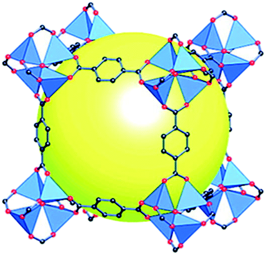 | ||
| Fig. 1 Scheme of a MOF structure (MOF-5) formed from tetrametallic SBUs (blue polyhedra) linked to terephthalic acid, with a cavity (yellow sphere) shown to capture gas/liquid molecules (reproduced from ref. 7 with permission from the American Chemical Society, copyright 2021). | ||
The structural versatility of MOFs (e.g. structural tunability, control of surface chemistry, control of pore size and shape, and composite synthesis capability) has allowed exploring these materials not only as potential platforms to capture CO2 but also as promising catalysts for CO2 conversion.10–12 Several strategies have been employed to finely tune the structures of MOFs, including the incorporation of open metal sites, amine functional groups, structural flexibility or framework interpenetration. These remarkable structural tunability and chemical functionality are enormously different from those of other porous materials such as zeolites and activated carbons, allowing the direct optimization of pore structures, surface functions, and other properties for specific applications. Additionally, MOFs often exhibit a higher pore volume and surface area than zeolites and activated carbons. CO2 adsorption and separation in MOFs have been studied intensively through experimental techniques and computational simulation methods in the past decade.13
The main challenge of CO2 catalytic conversion processes relies on the CO2 chemical inertness and thermodynamic stability of CO2 which typically require aggressive reaction conditions such as high temperature and high pressure, which, by consequence, are highly energy-intensive and environmentally unacceptable. Therefore, the conversion of CO2 under mild conditions requires the activation of CO2 with a highly efficient and selective catalyst such as metal–organic frameworks (MOFs). MOFs have been reported as promising candidates for CO2 capture and efficient catalysts due to their ultra-high porosity, crystallinity, and tuneable organic linkers resulting in materials with unique properties such as high surface area, high stability, open channels, and permanent porosity. MOFs therefore frequently take the edge over other adsorbents and catalysts for C1 chemistry and in particular for highly effective CO2 capture and CO2 conversion processes.14
To date, many reports related to CO2 capture and conversion have focused on the advances in the structural and molecular factors controlling the processes. However, in this review, we combine the main advances related to structural strategies to improve CO2 capture and conversion with key engineering affecting the large-scale application of these materials.
2. Synthesis approach and structural features of metal–organic frameworks
As a result of the large number of linkers available in the market and the high number of possible combinations in the synthesis of MOFs, in the last decade, there has been an exponential growth in the number of new MOF structures described in the literature.Synthesis optimization of MOFs is an essential step to obtain materials with desirable characteristics such as specific surface area and crystal morphology. Hence, different methods of MOF synthesis have been developed to fulfil these needs. As depicted in Fig. 2, MOF synthesis methods generally comprise conventional methods, i.e., those carried out by conventional electrical heating taking place in closed vessels under autogenous pressure above or below the boiling point of the solvent.15 Compared to the conventional methods, high-throughput methods (HT) which are closely connected with the concepts of automation, parallelization, and miniaturization have shown to be an ideal tool to investigate the MOF formation parameters, such as compositional (i.e., molar ratios of starting materials, pH, solvent, etc.) and process parameters (i.e., reaction time, temperature, and pressure) in a serial way.16 Alternatively to the conventional methods where the energy is generally introduced through conventional electric heating, energy can also be introduced through other means, for example, by an electric potential, electromagnetic radiation, mechanical waves (ultrasound), or mechanically.
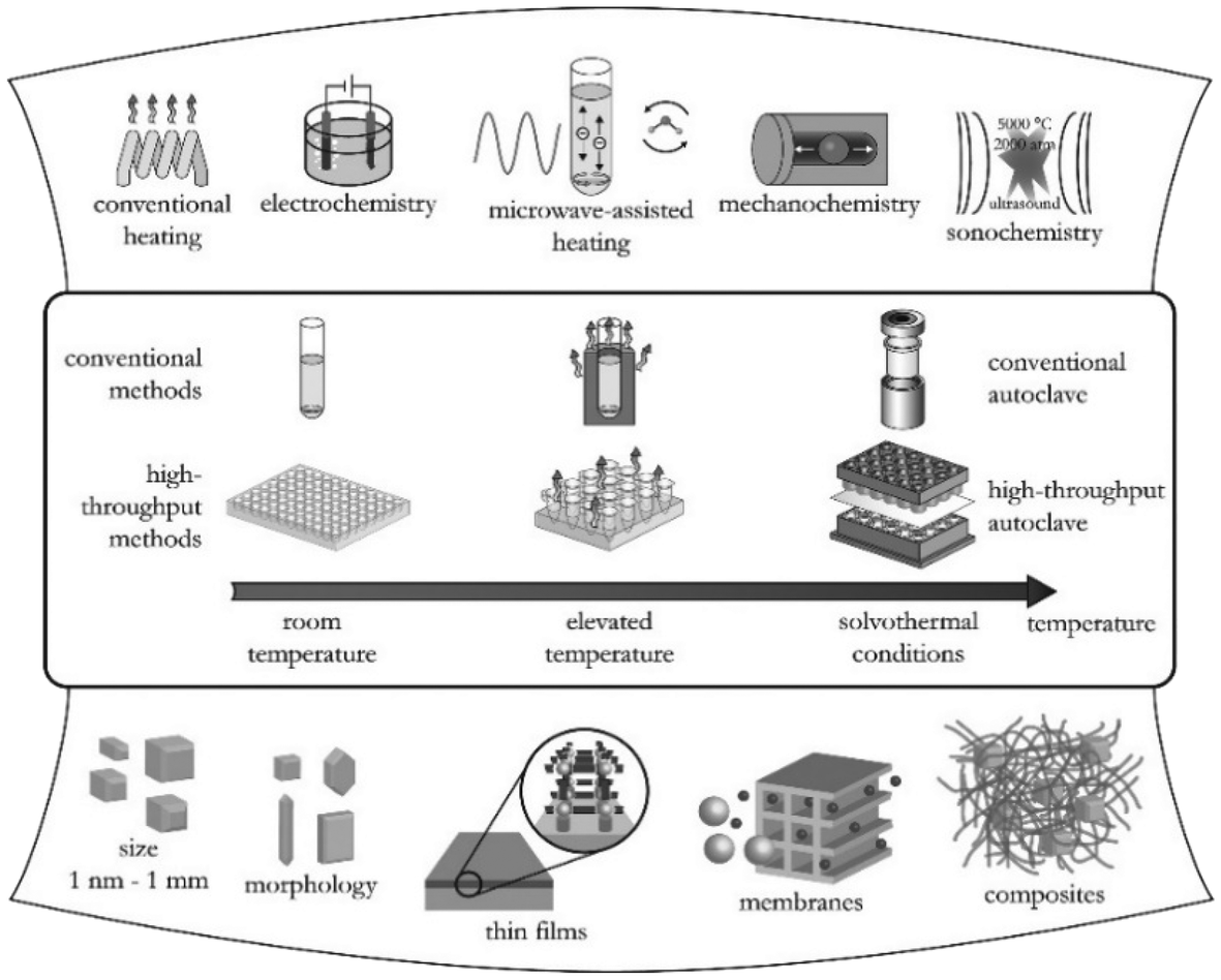 | ||
| Fig. 2 Overview of synthesis methods, possible reaction temperatures, and final reaction products in MOF synthesis (reproduced from ref. 16 with permission from the American Chemical Society, copyright 2021). | ||
The solvothermal synthesis of MOFs is one of the most widely used methods due to its facile implementation and relatively favoured up-scaling. Parameters such as the metal/ligand ratio, solvent, modulating reagent, and temperature affect the shape and size (growth) of the crystals greatly. A wide number of MOFs such as ZIFs,17 HKUST-1,18 UiO-66,19 and UiO-6720 have been synthesized for the first time using this method.
The microwave-assisted (MW) synthesis of MOFs is mainly focused on i) the acceleration of the crystallization, ii) nanoscale products, and most importantly iii) improving the porosity and the selectivity of polymorphs. One of the first examples of MW-assisted MOF synthesis was reported by Jhung et al. for Cr-MIL-100. In this synthesis, the solution of metallic salts and ligands was sealed in a Teflon autoclave and kept in an MW oven at 220 °C for 1, 2, and 4 h obtaining crystals with different shapes and sizes.21
In the electrochemical synthesis of MOFs, the metal cations diffuse to the reaction media through the anode, and the organic linkers are dissolved in the electrolyte, where they react with the anode. The advantage of the electrochemical synthesis of MOFs over other methods is the exclusion of anions coming from the metallic salts (i.e., chloride, nitrate, sulphate, etc.), which has been demonstrated to be beneficial for large scale production.16 A wide number of different MOF films and patterned coatings have been studied using this synthesis method.22
Mechanochemistry offers a green route for MOF production which is of great interest due to its advantages in comparison with other synthesis routes such as being solvent-free (or minimal amount of solvent), having short reaction times and without requiring external heat supply.23 However, the first limitation lies in the scaling-up of the synthesis; for instance, it can be classified as a batch processing technique with a low production yield. Herein, it is important to mention that a purification step must be added despite the solvent-free nature of this synthesis strategy.24,25
In sonochemical synthesis, cavitation promotes an intimate interaction between molecules and energy. For instance, the pressure and temperature in the hot spot of the bubble may reach 1000 bar and 5000 K (with heating and cooling rates of 1010 K s−1), respectively. Using sonochemistry to synthesize MOFs presents advantages of having a short synthesis time, being environmentally friendly, and being a high optimum energy-efficient process.16 The first MOF reported to be synthesized using sonochemistry was Zn–BTC, which consisted of MOF nanocrystals synthesized at room temperature and atmospheric pressure in 20% ethanol/water under ultrasound irradiation.26
Irrespective of the synthesis route, MOFs have provided unique opportunities for a wide number of applications. Due to their excellent physicochemical properties mentioned before, these materials have been applied in drug delivery, catalysis, sensor technology, gas storage and separation, water sorption applications, electrical energy storage, and luminescent materials, among many other advanced technologies.27
When low-carbon technologies are considered, MOFs serve as promising materials for CO2 capture and conversion due to their unique advantages such as (a) predictable and functionalizable structures, i.e. MOF structures can be easily predicted, and the structure can not only be designed as required, but can also be tuned. (b) Hybrid structures: MOFs are highly compatible with other materials to synthesize MOF composites. (c) Particular strengths for catalysis, such as high catalytic efficiency, facile separation and reusability. (d) The structural characteristics of MOFs allow a straightforward understanding of the structure–activity relationship, which ultimately helps to improve the materials and process design further.28
3. CO2 capture in MOFs
Presently mature technologies for CO2 capture at an industrial level are based on aqueous amine scrubbing; however, this technology involves a huge industrial separation process that is expensive and highly energy-intensive.14,29 CO2 capture using porous materials is gaining attention in different applications.30 Considering the extremely high surface area and the physicochemical surface properties thereof, the use of MOFs can serve as an alternative approach to reduce the energy penalty associated with CO2 capture due to their high porosity and chemical tunability.31–34 For instance, the use of different ligands can easily control the pore shape and size in MOFs, which is an essential requirement to have a preferential selectivity to CO2 over other similar molecules (H2, N2 and CH4).35 Different strategies have been developed to enhance and control the adsorption and capture of CO2 into the inner pores of MOFs, which are mostly related to the composition of ligands or post-synthesis modification of the frameworks. Table 1 summarises some of the most relevant CO2 capture amounts in MOFs with a variety of ligands and metals.| Adsorbent | Capacitya (mmol g−1) | Temperature (K) | Pressure (bar) | Ref. |
|---|---|---|---|---|
| a Some of the CO2 adsorption capacities have been converted to these units from the originally reported units. | ||||
| JUC-150 | 0.9 | 298 | 1 | 33 |
| MOF-2 | 0.6 | 298 | 1 | 39 |
| Norit RB | 2.5 | 298 | 1 | 39 |
| MOF-505 | 3.3 | 298 | 1.1 | 39 |
| MOF-74(Zn) | 4.9 | 298 | 1.1 | 39 |
| Cu3(BTC)2 | 4.1 | 298 | 1 | 39 |
| IRMOF-11 | 1.8 | 298 | 1.1 | 39 |
| IRMOF-3 | 1.2 | 298 | 1.1 | 39 |
| IRMOF-6 | 1.1 | 298 | 1.2 | 39 |
| IRMOF-1 | 1.1 | 298 | 1.1 | 39 |
| MOF-177 | 0.8 | 298 | 1 | 39 |
| MIL-100 (Cr) | 5.5 | 303 | 10 | 40 |
| Mg-MOF-74 | 9 | 298 | 1 | 42 |
| Ni-MOF-74 | 6.8 | 298 | 1 | 42 |
| Fe-MOF-74 | 6.8 | 298 | 1 | 42 |
| Co-MOF-74 | 6.6 | 298 | 1 | 42 |
| Zn-MOF-74 | 6 | 298 | 1 | 42 |
| Mn-MOF-74 | 5.9 | 298 | 1 | 42 |
| Cu-MOF-74 | 3 | 298 | 1 | 42 |
| LIMF-26 | 3.1 | 298 | 1 | 44 |
| NU-100 | 2.7 | 298 | 1 | 46 |
| PCN-61 | 23.5 | 298 | 35 | 47 |
| PCN-66 | 26.3 | 298 | 35 | 47 |
| PCN-68 | 30.4 | 298 | 35 | 47 |
| MIL-96(Al) | 5.2 | 303 | 20 | 48 |
| UTSA-20 | 5.4 | 303 | 1 | 49 |
| MIL-102(Cr) | 3.5 | 304 | 30 | 50 |
| UiO-66 (Zr) | 7.8 | 303 | 20 | 53 |
| UiO-66(Zr)-NH2 | 8 | 303 | 35 | 53 |
| Mg2(dobdc)(N2H4)1.8 | 5.5 | 298 | 1 | 54 |
| MIL-53 (Al) | 6.8 | 303 | 30 | 55 |
| Bio-MOF-11 | 4 | 298 | 1 | 59 |
| Cu-TDPAT | 6.1 | 298 | 1 | 60 |
| Cu-BTTri | 3.7 | 298 | 1 | 61 |
| ZnF(daTZ) | 3.3 | 298 | 1 | 64 |
| ZnF(aTZ) | 3.1 | 298 | 1 | 64 |
| ZnF(TZ) | 2.7 | 298 | 1 | 64 |
| ZIF-68 | 1.8 | 298 | 1 | 65 |
| ZIF-69 | 2.2 | 298 | 1 | 65 |
| ZIF-70 | 1.3 | 298 | 1 | 65 |
| ZIF-78 | 2.7 | 298 | 1 | 65 |
| ZIF-79 | 1.6 | 298 | 1 | 65 |
| ZIF-81 | 2.2 | 298 | 1 | 65 |
| ZIF-82 | 2.2 | 298 | 1 | 65 |
| TMOF-1 | 1 | 298 | 1 | 66 |
| MUF-15 | 3.6 | 298 | 1 | 67 |
| ZIF-7 | 5 | 195 | 1 | 78 |
| NOTT-202a | 12 | 298 | 30 | 80 |
| CALF-33-Et3 | 0.5 | 293 | 1 | 90 |
| CALF-33-Et2H | 1.1 | 293 | 1 | 90 |
| Ni-DOBCO | 5 | 298 | 1 | 91 |
| MOF-5 | 1 | 298 | 1 | 92 |
| ZIF-300 | 1.3 | 298 | 1 | 94 |
| ZIF-301 | 1.2 | 298 | 1 | 94 |
| ZIF-302 | 0.1 | 298 | 1 | 94 |
| SNU-100 | 3.2 | 298 | 1 | 111 |
| MIL-53 (Cr) | 10.2 | 303 | 25 | 124 |
3.1. Factors influencing CO2 capture in MOFs
CO2 adsorbed in porous materials (i.e. zeolites, silicas, polymers, and active carbons) is attached physically through weak interaction between CO2 and the pore. However, MOFs also capture CO2 by physisorption; their ultra-high surface areas give much higher uptake capacities compared to other materials. As depicted in Fig. 3, the ability to design MOFs that possess features such as open metal sites (OMSs), Lewis basic sites (LBSs), covalent-bound polar functional groups, tunable pore sizes, framework flexibility, or hydrophobicity has attracted enormous attention for CO2 capture.28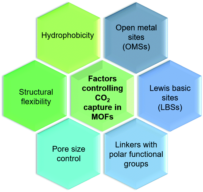 | ||
| Fig. 3 Factors controlling the CO2 capture performance in MOFs. | ||
HKUST-1 or Cu3(benzene-1,3,5-tricarboxylate or BTC)2 has been one of the first MOFs identified with OMSs, successfully studied in CO2 capture at either low pressure (up to 1 bar) or high pressure (up to 40 bar). For instance, Millward et al. reported HKUST-1 CO2 uptake capacity of about 10 mmol g−1 at 42 bar and ambient temperature, which is an exceptional value reached for this type of material.39 Recently, a computational study based on DFT and energy minimization principle was conducted to understand the interactions of CO2 with HKUST-1, which produced results in good agreement with previous experimental data indicating the appropriateness of computational methods as a potential means for the screening of MOFs for CO2 separation.40,41
Among all MOFs, those sharing the same ligand or the so-called isostructural MOFs have attracted considerable attention as a consequence of their extraordinary CO2 capture capacity. The family of isostructural MOFs based on 2,5-dihydroxyterephthalic acid (DOBDC), also known as M-MOF-74 or M-CPO-27 (M = Mg2+, Ni2+, Co2+, Zn2+) composed of an array of one-dimensional hexagonal channels with OMSs at the secondary building units (SBUs), has become one of the most well-studied sets of MOFs for CO2 capture due to their extraordinary CO2 uptake capacities at low pressures.42–44 The main limitation of OMSs–MOFs for CO2 capture leads to their ineffectiveness in the presence of water due to the stronger binding interactions of water than CO2, thus limiting the effectiveness of such materials for CO2 capture from flue gas streams.45
Following this work, a wide variety of MOFs bearing OMSs have been applied as CO2 adsorbents, including NU-1000, MIL-101, and PCN-68 offering plenty of opportunities for CO2 capture.46–50
For these very reasons, the design of MOFs decorated with LBSs has grown exponentially given their proven synergy, which leads to improved CO2 binding affinities, selectivity and CO2 reversibility. For instance, different MOFs have been functionalized using 2-amino-terephthalic acid (NH2-H2BDC) such as NH2-MIL-53, NH2-UiO-66, and NH2-MIL-125 and similar phenomena were observed.55,57,58 Additionally, other nitrogen-containing linkers, including pyrimidines, triazines, and azoles, have also been tested to synthesize MOFs with LBSs.59–62
Finally, to overcome the main limitation exposed in OMSs–MOFs related to water stability, Flaig et al. proposed the amino functionalization of several IRMOF-74-III as promising materials to improve the capture of CO2 in the presence of water.63 As shown in Fig. 4, Shi et al. reported the design of thermally and chemically robust amine-functionalized MOFs formed from triazolate linkers for post-combustion CO2 capture from flue gas containing water vapour (Fig. 4a). This research reached not only a CO2/N2 thermodynamic adsorption selectivity as high as 120 (Fig. 4b and c) but also a CO2/H2O kinetic adsorption selectivity up to 70, featuring distinct adsorptive sites at the channel centre for CO2 and at the corner for H2O, respectively (Fig. 4d).64
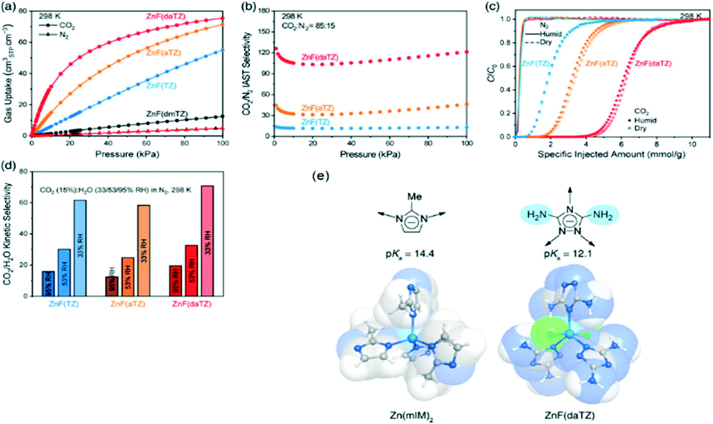 | ||
Fig. 4 Evaluation of the metal triazolate frameworks for high-humidity flue gas CO2 capture. (a) CO2 and N2 uptakes at 298 K and 0–1 bar. (b) CO2/N2IAST selectivity for the CO2/N2 (v![[thin space (1/6-em)]](https://www.rsc.org/images/entities/char_2009.gif) :v = 15:85) mixed gas at 298 K. (c) Breakthrough curves under dry and humid conditions (∼99% RH) for the CO2/N2 (v:v = 15:85) mixed gas at 298 K and a flow rate of 1 mL min−1. (d) CO2/H2O adsorption kinetic selectivities under various relative humidities. (e) Scheme of robust MOFs with azolate linkers (reproduced from ref. 64 with permission from the American Chemical Society, copyright 2021). :v = 15:85) mixed gas at 298 K. (c) Breakthrough curves under dry and humid conditions (∼99% RH) for the CO2/N2 (v:v = 15:85) mixed gas at 298 K and a flow rate of 1 mL min−1. (d) CO2/H2O adsorption kinetic selectivities under various relative humidities. (e) Scheme of robust MOFs with azolate linkers (reproduced from ref. 64 with permission from the American Chemical Society, copyright 2021). | ||
An example of the direct synthesis of MOFs with polar functional groups was reported by Barnerjee et al., who synthesised seven different ZIFs with a GME topology (Fig. 5a). ZIF-78 which is a MOF with –NO2 functional groups adsorbed up to 60 cm3 cm−3 CO2 at 298 K and 800 torr, which is much higher in comparison with those of the other MOFs from the series (Fig. 5b).65
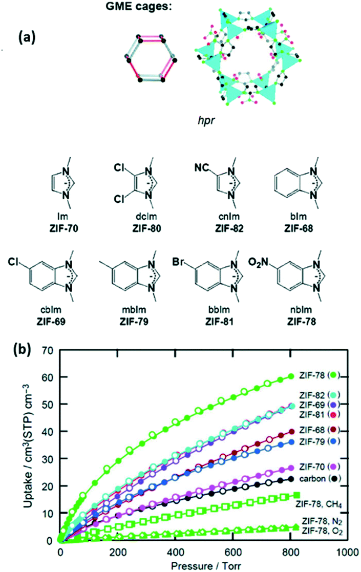 | ||
| Fig. 5 (a) Scheme of GME cage ZIFs, (b) CO2 adsorption isotherms at 298 K and 800 torr (reproduced from ref. 65 with permission from the American Chemical Society, copyright 2021). | ||
The second strategy, which involves the deviation from the commonplace metal-carboxylate chemistry in MOFs, has triggered the development of structures with a highly polar pore environment. The mixed linker TMOF-1 charged with sulfonated polar groups presented a total uptake capacity of up to 6.8 mmol g−1 at 308 K and 1 bar.66
The designability and flexibility of MOFs with polar functional groups have allowed using these materials for CO2 capture under different environments such as humid flows or mixed flows which are a more realistic representation of industrial flue gases.67–69
As shown in Fig. 6, the external stimuli or the initiator of the flexibility is found to greatly impact the structural change of the framework, such as phase change or change in unit cell parameters. The different flexibility modes in soft MOFs have been classified as breathing phenomena (Fig. 6A), swelling (Fig. 6B), linker rotation (Fig. 6C), and subnetwork displacement (Fig. 6D).
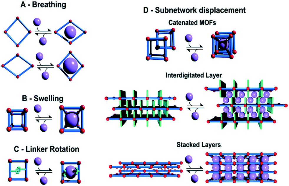 | ||
| Fig. 6 Classification of different flexibility modes of MOFs. One class is characterized by the change in unit cell volume (ΔV ≠ 0; A, B and D) while in the other case the unit cell volume does not change (ΔV = 0; C and D) (reproduced from ref. 73 with permission from the Royal Society of Chemistry, copyright 2021). | ||
It has been widely reported that certain flexible MOFs exhibit a breathing phenomenon as a consequence of CO2 adsorption.72–75 This effect is evidenced in the CO2 isotherm as a drastic change in the total CO2 uptake amount at a certain relative pressure. One of the first examples of flexibility in MOFs as a consequence of CO2 adsorption was reported by Aguado et al. in ZIF-7. Fig. 7 shows the CO2 adsorption isotherm of ZIF-7 at different temperatures and 200 kPa, where a drastic change in the total CO2 uptake is observed at a pressure of 50 kPa.76In situ synchrotron X-ray diffraction experiments have allowed classifying these structural changes in ZIF-7 as different MOF phases.77,78
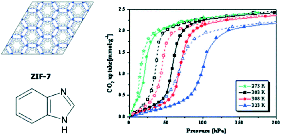 | ||
| Fig. 7 Schematic structure of ZIF-7 and CO2 adsorption isotherms for ZIF-7 at several different temperatures at 200 kPa (reproduced from ref. 76 with permission from the Royal Society of Chemistry, copyright 2021). | ||
Interpenetrated MOFs have shown to present high structural flexibility to gas molecule adsorption.79–82 A good example is the breathing of a 2-fold interpenetrated microporous MOF with a flexible tetrahedral organic linker and Zn2+ clusters that adsorb CO2. The CO2 adsorption isotherm revealed a drastic adsorption step at about 10 bar and a significant hysteresis during CO2 desorption reaching a total uptake of 7.1 mmol g−1 at 30 bar and 298 K.79
The competitive adsorption of water and its impact on the stability of MOFs have been a major concern for practical applications in CO2 capture. Many MOFs have been demonstrated to undergo structural degradation because the framework presents stronger interactions with the water than the CO2 due to its quadrupole moment.87–89 Hydrophobic MOFs, with improved water stability and low affinity toward water, are a class of promising adsorbents for CO2 capture under humid conditions.90–94
ZIFs have been characterized for their hydrophobic behaviour; for instance, Nguyen et al. reported the selective CO2 adsorption properties of hydrophobic ZIF-300, ZIF-301, and ZIF-302. These MOFs showed very low affinities toward water, as confirmed by their low water uptakes (6, 5.8, and 4.5 mg g−1 at P/P0 ≈ 0.8 and 298 K, respectively) while CO2 adsorption isotherms at 298 K and 800 torr indicated CO2 uptakes of 40, 40, and 36 cm3 cm−3, respectively.95
3.2. Post-synthesis MOF modification
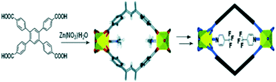
The development of strategies to introduce new sites with high affinity to CO2 into MOFs has been attracting attention recently due to their main approaches of non-altering or damaging the core of the structure.96 The post-synthesis modification (PSM) in MOFs has managed to enhance the CO2 affinity through strategies such as the modification of the linker of functional groups, e.g. amine groups and polar groups, or not only by exchanging the metal in the secondary building units (SBUs), but also by the modification, insertion or exchange of organic linkers.In 2009 Bae et al. reported the post-synthesis modification of a 3D non-catenated Zn-paddlewheel MOF (Fig. 8) by replacing coordinated solvent molecules with highly polar ligands leading to considerable enhancement of CO2/N2 selectivity. This post-synthesis modification allowed improvement of the CO2 selectivity at low loading over other molecules such as N2 or CH4.97
 | ||
| Fig. 8 Scheme of post-synthesis modification of a 3D non-catenated Zn-paddlewheel MOF (reproduced from ref. 97 with permission from the Royal Society of Chemistry, copyright 2021). | ||
The post-synthesis modification as a novel approach to enhance the CO2 capture in MOFs is not limited to the coordination environment of the metal cluster. Metal exchange in SBUs is also a promising technique that can improve the CO2 uptake and selectivity. For instance, UiO-66 initially formed from zirconium clusters was modified with titanium ions (Fig. 9a) showing a drastic increase in the total CO2 uptake (Fig. 9b).
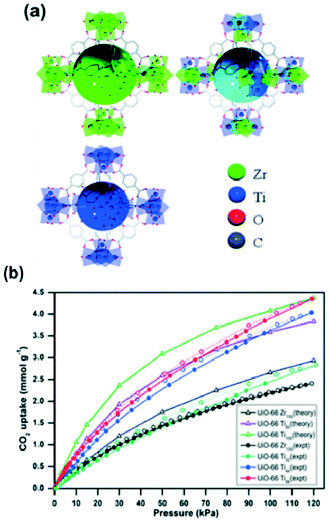 | ||
| Fig. 9 (a) A schematic representation of UiO-66 (Zr), UiO-66 (Zr,Ti) and UiO-66 (Ti); (b) CO2 isotherms for UiO-66 Zr and Ti at 273 K and 120 kPa (reproduced from ref. 98 with permission from the Royal Society of Chemistry, copyright 2021). | ||
The CO2 uptake in zirconium MOF UiO-66 was observed to be almost double with the post-synthetic exchange of Zr by Ti. This was explained to be due to the smaller pore size and higher adsorption enthalpy. Furthermore, the full effect is obtained with 50% Ti loading, precluding the need to fully substitute frameworks for CO2 capture.98
The post-synthesis exchange in MOFs is not restricted to the change of metal ions in the SBUs. For instance, different approaches have been reported to enhance the CO2 capture capability via linker exchange. Recently, Kronast et al. successfully used the PSM to introduce molecular gates into the MOF UiO-66-allyl. The obtained functionalities enable powerful tuning for the adsorption of CO2 over N2.99
3.3. MOF-based composite materials
The commercialization of MOFs has been limited by their crystalline or microcrystalline form, which inherently limits their integration into many technologies. A big effort has been done to incorporate and create a synergy of different matrices with potential realistic applications.In terms of CO2 uptake capacities in MOF composites, they are typically a great deal larger than those of the parent MOFs due to the generation of new pore environment(s), additional interactions at the interface between phases, and/or affinity of CO2 to the guest(s). Moreover, the plasticity and chemical stability of certain compounds utilized in the formation of MOF composites can lead to enhanced stabilities and mechanical properties of the resultant materials.16,28
MOF–polymer composites are a relatively recent addition to the class of MOF composites widely studied for CO2 capture and separation. They tend to attract a lot of attention owing to not only the variety of possible polymer functionalities as well as their light weight, facile processability and chemical stability but also the selectivity and applicability of MOFs for CO2 capture and separation.100 Different approaches have been used to develop elegant methods to synthesize MOF–polymer hybrid materials. Top-down approaches are performed when MOFs are initially synthesized and subsequently incorporated into polymeric materials, contrarily to what is done in bottom-up approaches, where hybrid materials are synthesized in conjunction with MOF formation.101
As summarized in Fig. 10, different approaches for MOF–polymer hybrid materials have been explored by research groups through the synthesis of mixed matrix membranes (MMMs), polymers grafted from MOF particles, polymers grafted through MOFs, polymers templating MOF growth and MOFs using polymer ligands.
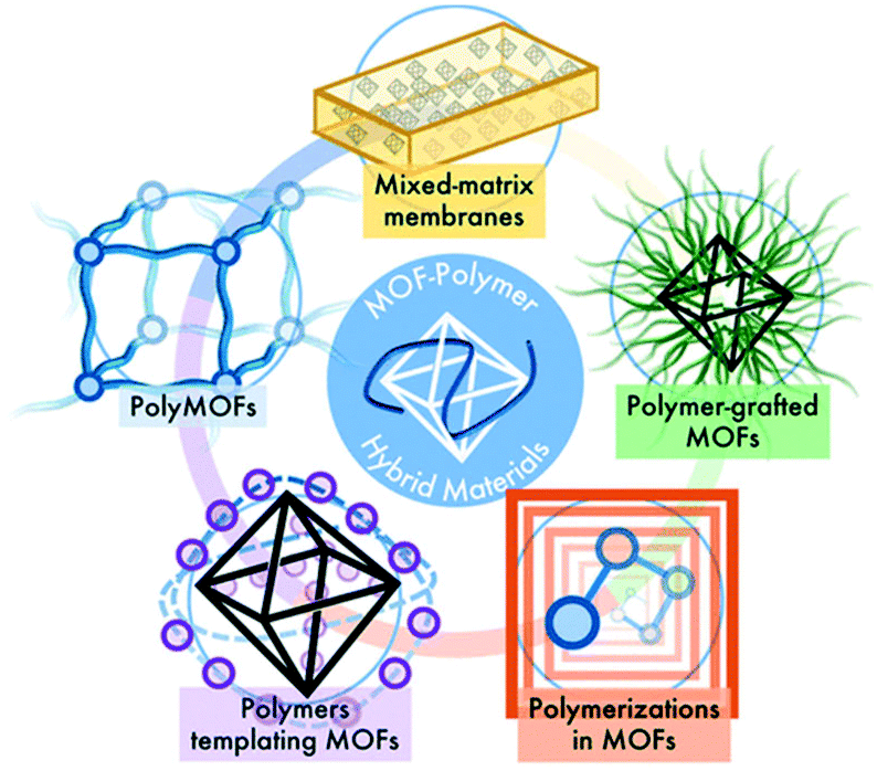 | ||
| Fig. 10 Overview of synthesis approaches for MOF–polymer hybrid materials (reproduced from ref. 101 with permission from the American Chemical Society, copyright 2021). | ||
The most widely used methods to synthesize MOF-based MMMs are the simple solution, dispersion and casting methods.102–104 For example, Su et al. used UiO-66-NH2 and PSF (polysulfone) to obtain MMMs (50 wt% MOF) with a remarkable selectivity for CO2 compared to CH4 and N2.105 The differences between MIL-53(Al) and MIL-53(Al)-NH2 PVDF-based membranes were reported by monitoring their selectivity toward a gas combination of He/CH4 and CO2/CH4 which was preferential to He over CH4 and CO2 over CH4 on the MIL-53(Al)-NH2 based composite.106 In the last decade, there is a high number of publications for MOF-based MMMs, such as PVDF/(UiO-66, UiO-66-NH2, MIL-53, MIL-101, HKUST-1 and ZIF-8) obtaining potential applications for flexible gas separation.104
3.4. Engineering aspects in CO2 capture in MOFs
Commonly, the evaluation of gas sorption properties of porous materials such as MOFs mainly relies on single-component gas sorption isotherms and crystallographic techniques, which are able to disclose the microscopic sorption sites and properties of gas molecules. However, studies on the macroscopic and practical mixture gas separation performance of MOFs remain limited. To bridge the gap between materials described in the last section and engineering aspects, we herein summarize the main approaches in the literature for the practical gas separation performance, including adsorption heat, ideal, and real gas selectivity, multicomponent gas adsorption, and cyclic mechanic stability. | (1) |
 | (2) |
Several publications explored the use of isosteric heat of adsorption as a parameter to determine the improvement in the adsorbate–adsorbent interaction and its impact on the gas selectivity of structural functionalized MOFs.110–112 A good example is the one reported by Park et al., which showed enhanced isosteric heat, selectivity, and uptake capacity of CO2 adsorption on SNU-100 by impregnation of various metal ions such as Li+, Mg2+, Ca2+, Co2+, and Ni2+.112 Due to the electrostatic interactions between CO2 and the extra-framework metal ions, the isosteric heat of CO2 adsorption was observed to be increased to 37.4–34.5 kJ mol−1 and the CO2 adsorption selectivities over N2 at room temperature are increased to 40.4–31.0, compared with those (29.3 kJ mol−1 and 25.5, respectively) of the parent MOF (SNU-100).
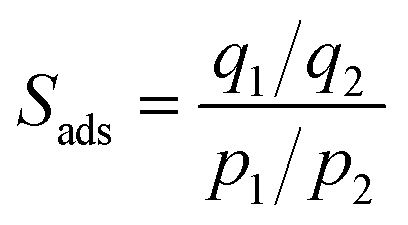 | (3) |
IAST has been widely applied in MOFs to study the selectivities for separation of mixtures of industrial interest such as N2/CO2, CH4/CO2 or CH4/N2.56,117–119 Billemont et al. use the IAST to study experimentally and theoretically the multicomponent co-adsorption of captured CO2, biogas and purified natural gas in MIL-100 (Fe) MOF. IAST showed to be a suitable model for such applications and seems appropriate for CO2/N2 separation in MIL-100 (Fe). Due to the versatility in terms of ligands and metals in MOFs, any adsorption application must be considered carefully, and IAST predictions should be supported by previous experimental validation.114
In a common breakthrough experiment, a volumetric or gravimetric apparatus is coupled with a gas chromatograph or mass spectrometer in order to measure the co-adsorption isotherms of CO2 and other gases.69,114,125 Due to the lack of commercial equipment for breakthrough experiments, many of these tests are carried out using in-house designed setups. However, the accuracy and the operational control can vary and by consequence, lead to experimental errors.
This engineering approach can be applied to evaluate MOF adsorbents in terms of multi-component adsorption performance and show a screen between ideal and practical adsorption at an industrial level. Even though MOFs can show a remarkable adsorption uptake for single-component adsorption, these materials do not necessarily perform well in binary or multi-component gas mixtures. To evaluate the co-adsorption performance of CO2 under real conditions, dynamic column breakthrough experiments are carried out.69,126 Xiang et al. reported the binary co-adsorption of CO2/N2 and CH4/CO2 in several different MOFs. In this publication, Mg-MOF-74 which is characterized by having open metal sites that enhance the CO2 capture in single-component adsorption experiments showed that under dynamic binary adsorption conditions (N2/CO2), it is able to adsorb up to 5.87 mmol g−1 at 298 K, which is less than half the total uptake amount reported for single-component adsorption capacity.127,128 Hu et al. reported the design of a lab-scale high accuracy device (Fig. 11) for the co-adsorption of CO2 into a highly stable MOF (UiO-66–OH) with an optimum aperture size (3.93 Å). They described the details of appropriate procedures for performing breakthrough experiments taking into account unavoidable pressure drop and changing the exit flow rate. In addition, they provided a complete analysis of breakthrough responses and demonstrated their application in a complete evaluation of MOF materials for post-combustion CO2 capture.129
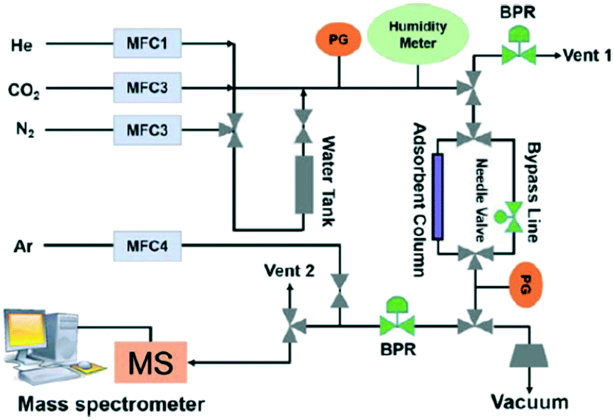 | ||
| Fig. 11 Breakthrough set-up for CO2 co-adsorption study (reproduced from ref. 129 with permission from John Wiley and Sons, copyright 2021). | ||
From a practical point of view, the evaluation of MOFs in CO2 co-adsorption in a binary mixture is not enough since real flue gas usually contains other molecules such as water (5–15%) or N2 which have a great influence on the CO2 adsorption performance.130–132 The assessment of the CO2 capture performance of MOFs in the presence of water vapour is indispensable and ternary CO2/N2/H2O breakthrough tests are needed.133 Most MOF adsorbents exhibit a decrease in the CO2 uptake capacities under wet conditions due to the competitive adsorption of H2O over CO2, especially for MOFs with vacant Lewis acid sites.134 For example, Mg-MOF-74 experiences an 83% decrease in CO2 uptake capacity under wet conditions from 5.87 to 1 mmol g−1.45,127
As discussed in the previous section, many efforts have been gathered to improve water stability in MOFs, mainly via amine functionalization and enhancing the structural hydrophobicity.135–137
Tanaka et al. reported a systematic study of tuning the size of ZIF-8 crystals and investigated the size dependence of n-butanol diffusion inside ZIF-8 crystals.145 By fitting the fractional uptake curve with mathematical models, they found that gas diffusion inside large crystals (>88 μm) is well monitored by a micropore diffusion model, while the surface resistance model is more suitable for smaller crystals. This result suggests that downsizing the crystal may lead to increased surface resistance.
The frequency response (FR) for gas diffusion measurements has been used as a tool to estimate gas diffusivity. In a typical frequency response experiment, one of the adsorption parameters (e.g. volume, flow rate, concentration, or pressure) is perturbed sinusoidally, and as a consequence, the other parameters react periodically but with different phase lag and amplitudes.146 These responses allow calculating the gas diffusivity in porous materials.134 Recently, concentration swing FR (CSFR) has been applied to study CO2 diffusion in large Cu–BTC single crystals, revealing a micropore diffusion coefficient of 1.7 × 10⁻⁹ m2 s−1 with negligible dependence on CO2 concentration from 0.1 to 10%.147
The process design is a fundamental step in order to potentiate the application of porous materials. Adsorbents are commonly supported by fine metal meshes in a fixed bed, or quartz wool if the material is in powder form. For MOFs, most of them are prepared in powder form and thus need to be pelletized before being secured in a fixed bed. In this way, the cross-column pressure drop can also be minimized to enhance the column breakthrough dynamics.129
MOF-based monoliths have appeared as an improved approach to potentiate the CO2 adsorption uptake.148,149 Connolly et al. reported the synthesis of metal–organic gel (MOG)-based macroscopic monoliths of UiO-66 with extraordinary properties to capture CO2 reaching a total uptake capacity of up to 0.67 g g−1 CO2 at 298 K and 40 bar.149 A similar strategy was performed by Lawson et al. to carry out gas stream purification at CO2 low pressure by the incorporation of tetraethylenepentamine in a novel post-synthesis monolith synthesis (Fig. 12).150
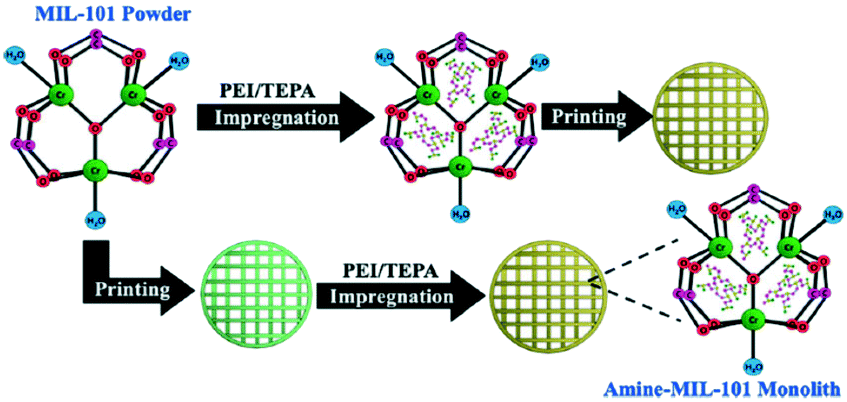 | ||
| Fig. 12 Formation process of amine-MIL-100 monoliths (reproduced from ref. 150 with permission from the American Chemical Society, copyright 2021). | ||
Glass MOF materials have been reported recently as a novel strategy to develop MOF monoliths through the development of MOF crystal–glass and MOF blended composites. MOF glasses are formed by a melt-quenching process which results in structural amorphization. For instance, Bennett's group has widely explored different approaches to form glass MOF-based composites such as porous MOF–glass, MOF crystal–glass, flux melted glass and blended ZIF—glass composites.151
At an industrial scale, the adsorption step is generally followed by another one to make a cyclic adsorption process which sometimes is carried out in a continuous manner if the adsorbent has a low price or the regeneration processes are complicated.152 In most processes, the regeneration of the adsorbent is essential since the disposal of the material as waste is not economical. In practice, the regeneration is performed by different routes, either in situ or externally by procedures such as an increase in the temperature, reduction in the partial pressure of the adsorbates, reduction in the concentration or inert gas purging.134 For the regeneration of MOFs, it is necessary to compare their respective heat of CO2 adsorption versus binary adsorption capacity since it is highly related to not only their cycling and regeneration processes but also their structural stability and chemistry surface.153
3.5. Mechanistic insights and operando studies for CO2 capture in MOFs
The interpretation of the CO2 capture efficiency based on ex situ characterization methods may be sometimes misleading. For understanding and further designing more efficient molecular organic framework (MOF) materials, it is required to clearly establish an intrinsic structure–property relationship, which describes the location of adsorption sites on the atomic-scale surface structure inside the pores and the identification of beneficial interactions for the adsorption of CO2. Therefore, visualization of the guest–host interactions involved in the gas sorption process is crucial to shed light on how these materials operate under working conditions and to elucidate potential mechanisms for the selective CO2 capture.From this perspective, the application of advanced characterization techniques with high spatial and time resolution under operation conditions is required to examine the porous frameworks during the gas sorption process. As shown in Fig. 13, the development of in situ and/or operando methods are gaining growing interest for monitoring the structural dynamic features, identifying the preferable CO2 binding sites and understanding the mechanism of CO2 adsorption. At this point, they must be distinguished from either in situ or operando terms. While in situ methods are referred to as the adsorption/desorption of specific probe molecules under controlled environment and temperature conditions, operando approaches allow one to directly correlate the structure, porosity and composition of framework porous materials to their performance under realistic operating conditions.154–157 A perfect operando experiment would correlate the nanoscale structure with the bulk scale performance considering the spatiotemporal heterogeneities.158 Therefore, any operando study requires in depth-understanding of local chemical and physical properties (molecular surface species and temperature/heat/mass transport gradients) under working environment conditions and besides has the capability to analyze these properties in real time with high spatiotemporal resolution.
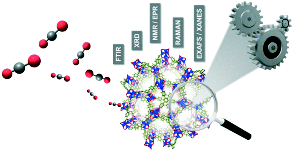 | ||
| Fig. 13 Representative illustration of the operando/in situ characterization approach applied to framework porous materials during the CO2 gas sorption process. | ||
In general, multiple in situ/operando characterization techniques have been applied to the study of CO2 capture in framework porous materials. Diverse examples can be found based on spectroscopic methods such as Raman and infrared (IR) spectroscopy, nuclear magnetic resonance (NMR) and electron paramagnetic resonance (EPR).159–161 These methods provide detailed information on the frameworks and on the host–guest interactions revealing the nature of these binding interactions. On the other hand, synchrotron characterization-based techniques are also widely used for the characterization of MOFs. These techniques essentially include extended X-ray absorption fine structure (EXAFS), X-ray absorption near-edge structure (XANES) and in situ diffraction/scattering experiments, which are typically used to determine the crystallographic sites preferred for CO2 capture inside the pores as well as their coordinative environment as a function of gas loading.162–164 In this section, we overview several examples representative of the most significant advances in the application of in situ/operando characterization techniques to elucidate the gas sorption mechanism in CO2 capture on porous framework materials.
Recently, Hadjiivanov et al. have reported an interesting review in which all the varieties of functionalities and porous structures of framework porous materials are described as well as the mechanisms of interaction with guest molecules measured by vibrational spectroscopy.160 Depending on the type of MOF, IR spectroscopy data indicate that carbon dioxide can be physically adsorbed on three types of centres: (i) coordinatively unsaturated metal cations, (ii) hydroxyl groups, and (iii) organic linker sites such as aromatic rings, carboxylate groups or C![[double bond, length as m-dash]](https://www.rsc.org/images/entities/char_e001.gif) C and C–C inter-ring bonds, among others. Furthermore, the adsorbed CO2 over MOFs functionalized with amines or amides undergoes CO2 chemical transformation. Couck et al. evidenced by in situ DRIFTS (diffuse-reflectance infrared spectroscopy) that this strong interaction is due to the formation of electron donor–acceptor (EDA) complexes between CO2, the amino group and the hydroxyl group of the framework structure.55 Meanwhile, the formation of this type of EDA complex is also possible in the absence of amines as suggested in the work reported by Llewellyn et al.165Operando IR spectroscopy was used to discriminate the type of CO2 interaction in MIL-101 (Cr), MIL-53 (Cr) and MIL-47 (V). CO2 is linearly coordinated on the Lewis acid coordinatively unsaturated Cr3+ sites of MIL-101 (Cr), while the carbon atom of CO2 interacts with the oxygen of the Cr–OH group forming an electron donor–acceptor complex on MIL-53 (V). In contrast, neither of these types of interactions are observed on MIL-47 (V), and CO2 pseudo-liquid-like species are formed inside the pores in the absence of any specific adsorption site.
C and C–C inter-ring bonds, among others. Furthermore, the adsorbed CO2 over MOFs functionalized with amines or amides undergoes CO2 chemical transformation. Couck et al. evidenced by in situ DRIFTS (diffuse-reflectance infrared spectroscopy) that this strong interaction is due to the formation of electron donor–acceptor (EDA) complexes between CO2, the amino group and the hydroxyl group of the framework structure.55 Meanwhile, the formation of this type of EDA complex is also possible in the absence of amines as suggested in the work reported by Llewellyn et al.165Operando IR spectroscopy was used to discriminate the type of CO2 interaction in MIL-101 (Cr), MIL-53 (Cr) and MIL-47 (V). CO2 is linearly coordinated on the Lewis acid coordinatively unsaturated Cr3+ sites of MIL-101 (Cr), while the carbon atom of CO2 interacts with the oxygen of the Cr–OH group forming an electron donor–acceptor complex on MIL-53 (V). In contrast, neither of these types of interactions are observed on MIL-47 (V), and CO2 pseudo-liquid-like species are formed inside the pores in the absence of any specific adsorption site.
Nuclear magnetic resonance (NMR) and electronic paramagnetic resonance (EPR) spectroscopy techniques provide detailed information at the molecular level on the local chemical environment, including molecular motion in metal–organic frameworks. Lu et al. performed an interesting study based on computational molecular dynamics and in situ solid-state NMR measurements to elucidate the CO2 adsorption mechanism on an α-magnesium formate MOF.166 They observed that CO2 motion is restricted at high temperatures and demonstrated that the CO2 guest interacts efficiently with the hydrogen atoms of the formate linker oriented toward the interior of the MOF pores. It should be mentioned that NMR spectroscopy is also a powerful tool to study the diffusion of guest molecules within the pores and channels of porous framework materials.162 The knowledge of the kinetics gas loading is crucial to optimize gas sorption processes on an industrial scale.
In contrast to NMR spectroscopy, EPR deals with the interaction of electromagnetic radiation with inherent magnetic moments associated with unpaired electron spins present in paramagnetic species such as transition metals (e.g. Ti3+, Mn2+, Cu2+, Cr3+or Co2+) or inorganic/organic free radicals. EPR spectroscopy provides unique information about the nature, coordination environment, symmetry and electronic ground state of paramagnetic species in framework porous materials.159 EPR is a very sensitive technique and is capable of analyzing the local geometry of paramagnetic metal ions even in small concentrations randomly distributed over a diamagnetic parent framework.167 By means of in situ EPR measurements, Mendt et al. investigated the breathing behaviour during the CO2 sorption process on the flexible and pillared-layered MOF Zn1.9Cu0.1(BME-bdc)2(dabco).168 The monometallic MOF Zn1.9(BME-bdc)2(dabco) parent exhibits a reversible transition from a narrow pore phase to an expanded open pore upon guest inclusion. The doping with paramagnetic Cu2+ ions as probe molecules allowed this phase transition to be monitored on a microscopic scale using EPR spectroscopy. This technique is highly sensitive to small structural changes in the Cu2+ coordination induced by CO2 interaction, and the results obtained showed a remarkable breathing behavior with a cell volume increase of 20% for the large pore phase.
X-ray absorption spectroscopy (XAS) and high-resolution X-ray diffraction (HR-XRD) measurements using radiation synchrotron sources are very useful approaches to analyze the local atomic structure related to the geometry, coordination and interatomic distances as well as the positions of adsorbed guests in the pores. The comprehensive review reported by Soldatov et al. overviewed the potential of X-ray absorption spectroscopy for the in situ characterization of MOFs.164 In an interesting study, Du et al. investigated the CO2 adsorption mechanism on three commercial MOFs (Cu–BTC, Fe–BTC and ZIF-8) by using XANES analysis and EXAFS fittings.169 They found that the oxidation states, bond distances and coordination numbers of the first shell remain unaltered in the three solids during the adsorption/desorption of CO2 suggesting that physical adsorption is the main driving force in the CO2 capture by the three framework porous materials. This observation reveals that CO2 capture in MOFs is energetically much more efficient than capture by chemical adsorbents based on amines because physical adsorption requires less energy for regeneration.
On the other hand, Giacobbe et al. reported an exhaustive study to disclose the adsorption sites occupied by the CO2 gaseous probe and the nature of host–guest interactions on the metal–organic framework Fe2(BPEB)3 as a CO2 adsorbent by means of in situ/operando high-resolution and high-energy X-ray diffraction measurements at several pressures and 298 K.170 This study provides structural details during CO2 adsorption on a rigid MOF with remarkable CO2 adsorption capacity in the absence of framework breathing, phase transition, exposed metal sites or functional groups with high CO2 specific affinity on the skeleton of ligands. The MOF Fe2(BPEB)3 presents a structure formed from 1D triangular channels (Fig. 14(a)) in which three types of adsorption sites (CO2-1, CO2-2 and CO2-3) were proposed as shown in Fig. 14(b). The pair distribution function (PDF) analysis presented in Fig. 14(c) and (d) shows the distribution of interatomic distances as a function of CO2 loading on Fe2(BPEB)3. These functions are typical of disordered or poorly crystalline materials like Fe2(BPEB)3, and the peak emerging at 3.2 Å suggests the occurrence of new cooperative guest–host and guest–guest binding interactions with increasing CO2 loading. Based on these observations, the authors demonstrated that CO2 molecules interact with the carbon atoms of the triple bond and of the penta- and hexa-atomic rings of the BPEB2− linkers, and these results were supported with molecular dynamics simulations. This work represents a clear example of the potential application of in situ/operando high-resolution X-ray diffraction analyses to gain structural insight during gas sorption on framework porous solids.
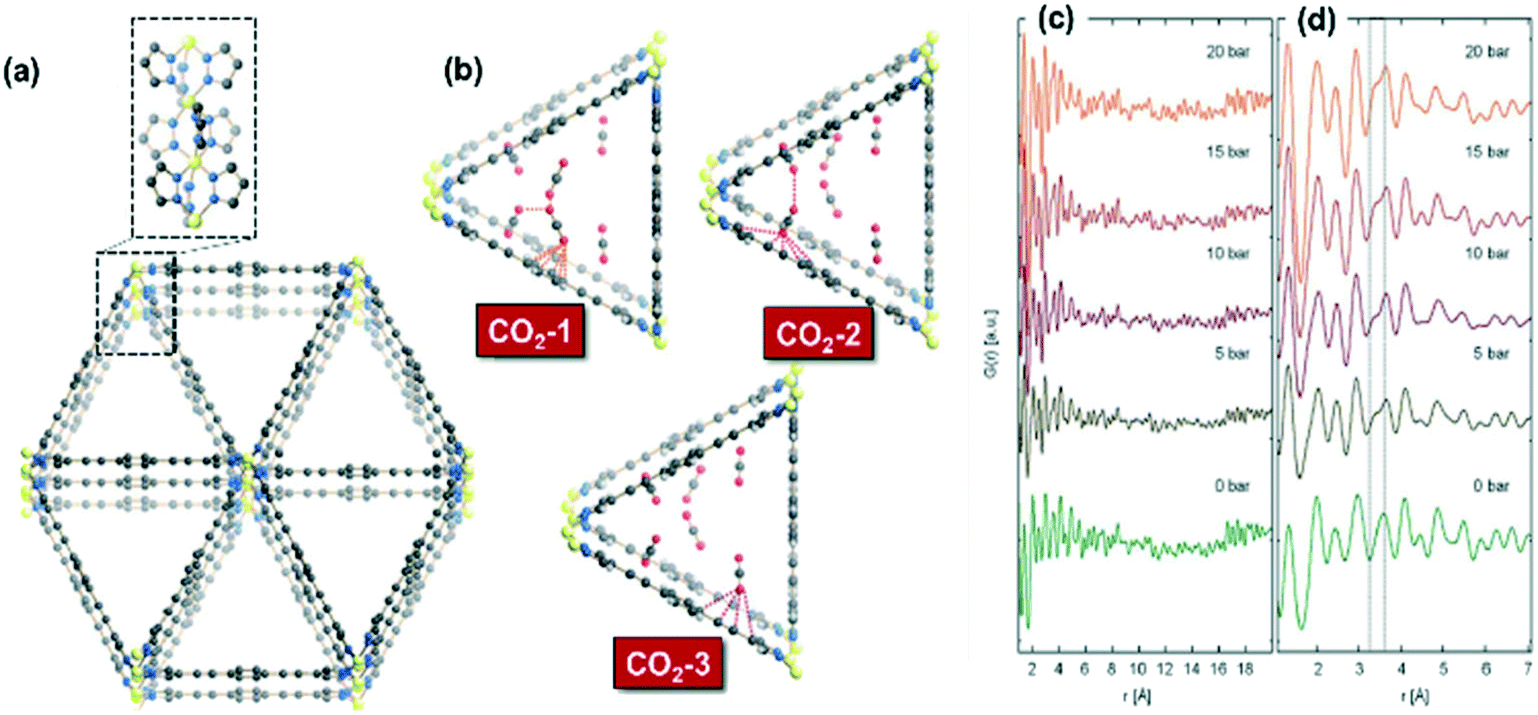 | ||
| Fig. 14 (a) Crystal structure of Fe2(BPEB)3 and portion of the 1D metal chain exposed along the a-axis; (b) representation in perspective along the [100] direction of host–guest and guest–guest interactions involving the three independent CO2 adsorption sites at 10 bar and 298 K in Fe2(BPEB)3; (c) pair distribution functions (PDFs) of Fe2(BPEB)3 at different CO2 loadings; (d) magnification in the 1–8 Å range. Atoms: carbon, grey; hydrogen, light grey; iron, yellow; nitrogen, blue; oxygen, red (reproduced from ref. 170 with permission from the Royal Society of Chemistry, copyright 2021). | ||
In conclusion, we can highlight that the application of in situ/operando methods provides new insights into the CO2 adsorption process. These methods allow locating the adsorption sites inside the pores and the identification of the host–guest binding interactions beneficial for the adsorption of a specific guest, ultimately helping to design rationally more efficient porous framework materials for CO2 capture and its subsequent utilization.
4. MOFs as advanced catalysts for gas-phase CO2 conversion
C1 chemistry and catalysis, especially referred to as carbon dioxide (CO2) transformation, is vital for clean fuel and chemical production to facilitate the transition towards sustainable societies. Burning biomass, organic waste and fossil fuels generates a huge amount of CO2 emissions, which leads to adverse climate change and drives the scientific community to focus their attention and efforts on CO2 conversion, especially on the transformation of CO2 into valuable products.171–175Presently, the CO2 capture and storage (CCS) technology is considered to be the most effective way to curb CO2 pollution on a large scale. Nevertheless, most of the current CCS approaches are deemed highly energy-intensive resulting in elevated cost and limiting their implementation in industrial practice. Hence CO2 capture and utilisation (CCU) are emerging as an alternative or a complementary strategy to CCS to mitigate CO2 emissions. Among the multiple CO2 conversion alternatives, chemical CO2 recycling in the gas phase constitutes a straightforward approach for effective CO2 conversion to value-added products like syngas or synthetic methane. In this scenario, some traditional processes such as the dry reforming of methane, the CO2 methanation and the reverse water gas shift have gained renewed interest from the CO2 utilisation perspective.176–179 Indeed, these reactions represent flexible routes to upgrade CO2, and their application at an industrial scale could substantially reduce CO2 emissions. Nevertheless, the relatively inert nature and low reactivity of carbon dioxide pose formidable challenges to successfully accomplish these reactions. In particular, the design of highly effective, stable and selective catalysts able to operate under realistic flue gas conditions remains an open quest for the catalysis and reaction engineering community.
In this context, metal–organic frameworks (MOFs), as a relatively new emerging family of crystalline porous materials, have demonstrated promising features as heterogeneous catalysts or supports/precursors to overcome the CO2 conversion challenge.180 These materials, also known as porous coordination polymers (PCPs), have unique features and advantages, such as adjustable framework structures, defined and diverse crystal structures (especially confined microenvironment), hybrid composition, etc.,181–183 which enable their excellent performance in various applications including their use as heterogeneous catalysts.
In this section, recent advances in MOFs and MOF-based heterogeneous catalysts for CO2 chemical conversions, including CO2 hydrogenation to methane (methanation reaction), CO2 hydrogenation to CO (reverse water–gas shift reaction) and dry reforming of methane, are reviewed. Overall, we will outline key aspects such as the catalytic performance, catalyst design and advantages of MOFs for CO2 conversion in line with the spirit of this special issue.
4.1. CO2 methanation
In recent years, the CO2 methanation reaction has gained renewed interest because of its role fundamental for implanting the power-to-gas (PWG) technologies in future energy systems, in which captured CO2 can be transformed into utilizable methane using renewable hydrogen.184 One of the most fascinating applications of the methanation reaction is the possibility of transforming the Martian carbon dioxide atmosphere into methane and water for fuel production facilitating long-term space exploration missions by space agencies such as NASA.185CO2 methanation was first studied by Paul Sabatier and Jean-Baptiste Senderens at the beginning of the twentieth century.186 This reaction is a highly exothermic (ΔH298K = −165 kJ mol−1) and thermodynamically favourable (ΔG298K = −131 kJ mol−1) process that, in the light of Le Chatelier's principle, proceeds at moderate pressures and low temperatures according to the following stoichiometric reaction (4):
| CO2(g) + 4H2(g) → CH4(g) + 2H2O(g) | (4) |
Due to the exothermic character of the reaction, it presents apparent kinetic limitations and requires an optimal catalyst to achieve a satisfactory reaction rate and methane selectivity.187 According to the most recent state of the art, several reviews have been reported discussing the successful development of heterogeneous catalysts and the mechanistic relevant aspects of CO2 methanation.188–192 So far, the most efficient systems proposed for CO2 methanation are based on Ni and/or Ru metal-supported catalysts.193 Other metals such as Fe, Co, Rh, Pt, Pd or Au have also been tested for CO2 methanation, although these metals are generally less active and/or selective.194 From the industrial viewpoint, Ni-based catalysts have gained major interest due to their affordable price. Nevertheless, Ni sintering and coke accumulation become important limitations, and new directions on the catalyst design are addressed.
From this perspective, MOFs and their derivative single-site catalysts have been recently reported as robust and promising catalysts for low-temperature CO2 methanation. However, the development of MOF-based catalysts for CO2 methanation is still in its infancy and the most relevant papers have been published in the last four years. It is well known that CO2 hydrogenation is a structure-sensitive reaction, namely the activity and selectivity depend on the metal particle sizes and the exposed facets.195 In this sense, the utilization of MOFs as precursors for obtaining highly-dispersed metal active sites and single/dual-atom and cluster catalysts has emerged as a very interesting alternative for synthesizing highly stable, selective and active catalysts for CO2 methanation.196–200
One of the pioneering studies using the MOF templating strategy for preparing highly active catalysts in CO2 methanation was reported by Lippi et al.201 These authors synthesized a Ru/ZrO2 catalyst derived from a Ru-impregnated UiO-66 MOF and achieved CO2 conversions in the 96–98% range with high selectivity to methane for more than 160 h of testing at 350 °C and 5 bar. In the same line, Zeng et al.202 prepared a highly dispersed Ni catalyst supported on porous hydrous zirconia derived from the metal–organic framework precursor UiO-66 treated with a strong base. Ni2+ sites were incorporated by adsorption onto the hydroxyl-rich hydrous zirconia and subsequently converted into highly dispersed metallic Ni sites for CO2 methanation, as shown in Fig. 15. The final catalyst showed good activity (TOF of 345 h−1) and stability (4% decrease in activity after 100 h) with a CH4 selectivity of more than 99% at 350 °C and 40 bar. In another study, Jiang et al. also used the UiO-66 MOF directly as a support for highly and uniformly dispersed palladium nanoparticles.203 These catalysts showed a high activity in CO2 methanation, and the optimal performance was achieved at 340 °C and 40 bar with a CO2 conversion of 56%, a CH4 selectivity of 97.3% and a space–time yield (STY) of 856 g h−1 kgcat−1.
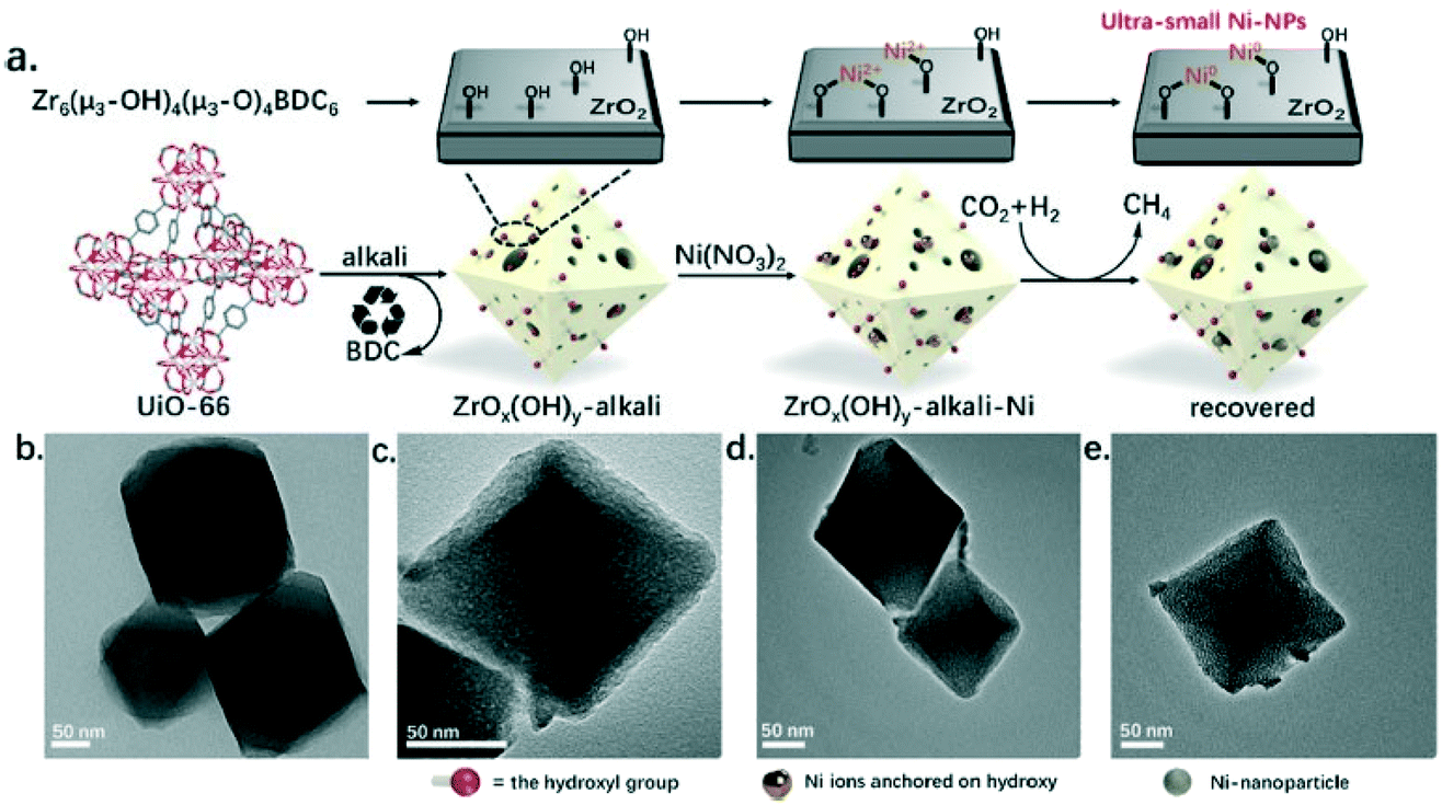 | ||
| Fig. 15 (a) Schematic representation of the steps followed for the preparation of a highly dispersed Ni catalyst supported on hydrous zirconia derived from the UiO-66 MOF precursor treated with a strong base, and their corresponding TEM micrographs (b–e) (reproduced from ref. 202 with permission from the American Chemical Society, copyright 2021). | ||
Other examples highlight the opportunity of using MOFs as host matrices to confine and stabilize metal single atoms, clusters or nanoparticles. For instance, Zhao et al. reported the utilization of the UiO-66 MOF to encapsulate ultrasmall Ni nanoparticles (NPs) with particle sizes ranging from 1.6 to 2.6 nm.204 In this system, the Ni NPs were highly uniformly dispersed and well isolated by the UiO-66 frameworks, thus avoiding metal sintering effectively. Compared with other traditional supports such as SiO2 and ZrO2, Ni@UiO-66 catalysts showed a significantly enhanced catalytic performance for CO2 methanation in terms of CO2 conversion (57.6%), selectivity (close to 100%) and long-term stability (100 h) at 300 °C. The highly dispersed Ni NPs decrease the activation energy and facilitate the CO2 activation. In a similar form, Zhen et al. developed an efficient catalyst for CO2 methanation based on Ni NPs confined in a highly ordered porous MIL-101 framework.205 These authors demonstrated that in this conformation the Ni (100) facets of the nanoparticles are more exposed and by means of DFT calculations it was estimated that the Ni (100) planes decrease the potential energy barrier for CO2 dissociation.
Framework porous materials have been extensively used for preparing MOF-derived porous metal@carbon (M@C) composites with specific metal NPs confined in carbon shells with high dispersion. Recently, Prinz et al. designed a well-dispersed nickel metal catalyst from thermal decomposition of a Ni-MOF precursor and evaluated the structure–activity relationship during CO2 methanation using in situ X-ray absorption spectroscopy (XAS) and pair distribution function (PDF) analysis.206 The study reveals that controlling the atmosphere and temperature of thermal decomposition of the Ni-MOF precursor can obtain a Ni@C catalyst in which a carbon matrix of high specific surface area embedded small particles of Ni resulting in a very stable catalyst with high dispersion of active Nifcc sites. Li et al. also reported an interesting study in which a Co-based zeolitic imidazolate framework (ZIF-67) was utilized as a precursor to obtain cobalt nanoparticles inside a carbon matrix in the range from 7 to 20 nm with high resistance to metal sintering.207 The crystal size and morphology of ZIF-67 were controlled by adding different loadings of cetyltrimethylammonium bromide (CTAB) as a surfactant in the original solution during the preparation. The results obtained suggest that after carbonization, the sample kept the size and morphology of the original ZIF-67 crystal with a distorted surface. The optimal amount of CTAB to obtain a carbonized sample with the highest BET surface area and micropore volume was 0.01 wt%, and this catalyst exhibited the highest CO2 adsorption capacity, CO2 conversion (52.5%) and CH4 selectivity (99.2%) at 270 °C and 72 L g−1 h−1 gas hourly space velocity. In another study, Lin et al. prepared hierarchical Ni@C nanospheres composed of dispersed Ni nanoparticles encapsulated by carbon layers, as shown in the images obtained by FESEM and TEM (Fig. 16(A)).208 The catalytic activity data presented in Fig. 16(B) show that this Ni@C hybrid is an efficient catalyst for CO2 methanation at atmospheric pressure achieving a CO2 conversion of 60% and a CH4 selectivity of almost 100% at 250 °C and 1 bar. From the mechanistic point of view, the authors proposed that CO2 is activated by electron transfer from the rich d-electrons of metallic Ni NPs to the lowest unoccupied molecular orbital (LUMO) of CO2 molecules. The reaction proceeds through H2 dissociation and formation of Ni–C–(OH)2 intermediates that subsequently are hydrogenated to water and methane as products as shown in Fig. 16(C).
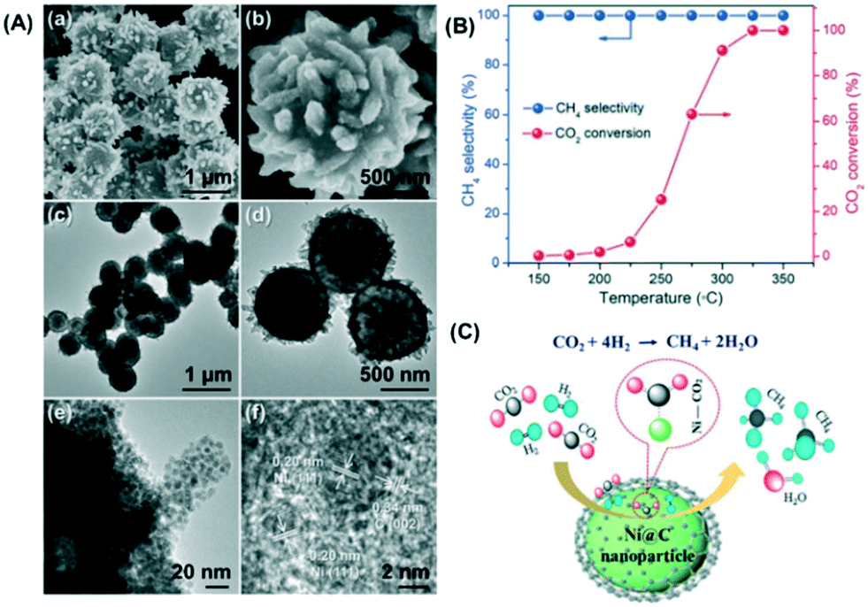 | ||
| Fig. 16 (A) FESEM micrographs (a and b), TEM images (c–e), and HR-TEM image (f) of the hierarchical Ni@C hollow nanospheres; (B) CO2 methanation performance of the Ni@C catalyst at different reaction temperatures; (C) schematic representation of CO2 methanation over the Ni@C catalyst (reproduced from ref. 208 with permission from the Royal Society of Chemistry, copyright 2021). | ||
Based on fundamental understanding, single-atom based catalysts and confined nanoparticles are an excellent choice to elucidate the mechanism of CO2 methanation or other energy-related processes at the atomic level. The design of single-atom and metal clusters from metal–organic frameworks presents an ideal platform to investigate the structure–activity relationships with the help of in situ characterization methods and theoretical calculation approaches. As Hou et al. remarked in their recently published review,197 although the development and knowledge of single/dual-atom and nanoparticle confined catalysts derived from MOFs are still in the early stages, these systems will be crucial to gain in-depth information at the nanoscopic scale and to design more robust, efficient and economic catalysts achieving the connection between heterogeneous and homogeneous catalyses.
4.2. RWGS
Catalytic conversion of CO2 to CO by the reverse water–gas shift (RWGS) reaction (CO2 + H2 ↔ CO + H2O) has been largely considered as one of the most prospective application processes for CO2 hydrogenation. CO2 conversion via the RWGS reaction not only permits high CO2 conversion efficiency but also facilitates CO2 reduction to CO, a more valuable chemical which can be used as a raw material in a downstream process such as the FTS reaction or methanol synthesis to produce other high value-added fuels and chemicals.209However, the RWGS reaction is an endothermic reaction, favoured thermodynamically and kinetically at high temperatures resulting in a remarkable energy-demanding process. Consequently, common catalysts often used are easily deactivated by sintering or carbon deposition at these temperatures, hindering the large-scale application of the CO2 conversion via the RWGS reaction.
Currently, research on the RWGS reaction mainly focuses on the study of noble metal catalysts,210–212 and in more limited extension transition metal catalysts are considered.213,214 Due to the great significance of the RWGS reaction in both fundamental research and practical applications, the design of low-temperature and high activity RWGS materials has also attracted significant attention recently.214 Indeed, if the RWGS reactor is conceived to be coupled with a downstream upgrading reactor such as an FTS or MeOH synthesis reactor, the temperature and pressure gaps among both units must be overcome. Hence a medium–low temperature RWGS catalyst is deemed crucial to complete the “CO2 to fuel/chemical” cycle.213
On the other hand, monodispersed supported metal nanoparticles (NPs) have been extensively reported to exhibit catalytic activity in the production of industrially viable chemicals using CO2 as a carbon pool as discussed in the CO2 methanation section. Nevertheless, the catalytic activity of metal nanoparticles is limited by their small size, surface quantum, and macro-quantum tunnel effects,215 and a major barrier to their widespread use is the potential for sintering and aggregation.
Recently, researchers have found that the use of porous metal–organic frameworks (MOFs) as supports to form monodispersed and isolated metal nanoparticles is an effective strategy. MOFs have been utilized as a new type of support for metal NPs as they have multiple outstanding properties such as controllable topologies, structures and geometries, porosities, and exceptionally high surface areas.216,217 Such distinctive properties are deemed crucial to obtain well-dispersed nanoparticles hence decreasing the possibility of active phase sintering.
Aside from MOF implementation as catalytic supports and somehow stabilizing frameworks, recent studies validated MOFs as catalysts themselves, in which case, metallic centres or pseudo-organic linkers such as porphyrins are responsible for the catalytic activity.218 Alternatively, MOFs have been successfully applied as precursor materials to design highly active RWGS catalysts via MOF decomposition.219 Although significant achievements have been obtained in the field of catalysis by MOFs, the study on the CO2 conversion via a RWGS reaction using these emerging materials is still in its early stages.
Xu et al. in 2017 reported the first example of a MOF-catalysed RWGS reaction, using Au@MOF composite catalysts.220 Zr(IV)-based MOF UiO-67 was selected as a support owing to its porosity, high surface area and high thermal stability (≈500 °C). For the active phase, Au3+ was adsorbed into the surface cavities of UiO-67, and during the reduction process, AuNPs were controllably grown on the UiO-67 surface simultaneously accompanied by their self-immobilization in the cavities or the surface pores, resulting in highly isolated and well-dispersed AuNPs on MOF UiO-67 (Fig. 17A).
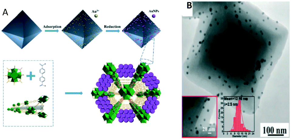 | ||
| Fig. 17 A) Schematic of the catalyst synthesis strategy; B) transmission electron microscopy (TEM) images of Au@UIO-67 (reproduced from ref. 220 with permission from the Royal Society of Chemistry, copyright 2021). | ||
In this study, TEM images of the post-RWGS reaction sample were reported confirming the excellent dispersion of AuNPs within the engineered Au@UiO-67-catalysts (Fig. 17B). These cleverly designed catalysts serve as a reassuring example of sintering mitigation of AuNPs when framed within the MOF structure despite the high temperature needed for the RWGS.
Along with resistance to sintering, interesting catalytic results were obtained for the Au@UiO-67 composite, which merits further discussion. Outstanding CO selectivity was reached (96.5%), and only a trace of CH4 was detected. Fig. 18 shows the influence of the main reaction parameter on the overall performance. The CO2 conversion of Au@UiO-67 for the RWGS reaction gradually increased upon increasing the reaction temperature due to the endothermic nature of the reaction (black bars). Below 300 °C, the reaction showed almost no conversion because of the stable nature of the C–O bond in the CO2 previously mentioned. Above 350 °C, the CO2 conversion increased notably reaching 30% at 408 °C. Regarding pressure studies (red bars), the CO2 conversion of the RWGS reaction gradually increased with pressure. Despite the RWGS being in principle unaffected by pressure if we stick to Le Chatelier's principle, the positive effect of pressure was ascribed to the greater reactant concentration being in contact with Au nanoparticles' active sites at high pressure, improving the overall conversion. The impact of the reactant feeding ratio (blue bars) was also studied and higher CO2 conversion was obtained upon increasing the H2:CO2 volume ratio, in good agreement with studies conducted with the thermodynamic process.221
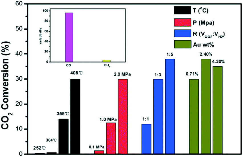 | ||
| Fig. 18 CO2 conversion at different temperatures (in black), pressures (in red), volume ratios (in blue) and Au contents (in green) for the RWGS reaction. Selectivities to CO and CH4 (inset) (reproduced from ref. 220 with permission from the Royal Society of Chemistry, copyright 2021). | ||
Finally, the authors studied the effect of Au loading (green bars). Interestingly a maximum CO2 conversion was observed over the Au-promoted UiO-67 MOF when 2.4 wt% of Au was considered. Beyond this point, the conversion drops. Generally speaking, the main advantage of this kind of material is the porous nature of the MOFs, which promotes the formation of isolated and well-dispersed active phase nanoparticles. However, AuNPs deposited on UiO-67 slightly tend to migrate and agglomerate, reducing the number of active sites at high temperatures. Therefore, when the AuNP loading is high, the overcrowding presence of AuNPs increased the possible migration and sintering at the expense of CO2 conversion. Additionally, a longevity test was carried out showing that the Au@UiO-67 catalyst exhibited relatively stable catalytic performance, indicating that AuNPs do not easily aggregate on the surface when the optimum gold loading is considered.
Hence it is clear that highly dispersed Au nanoparticles successfully loaded onto monodisperse octahedra of UiO-67 work very well for the RWGS. Herein MOF functionalities allow the incorporation of different nanoparticles in a non-agglomerated fashion and are capable of controlling the spatial distribution of nanoparticles in this material. Furthermore, engineered AuNP@UiO-67 composites encompass the benefits of the molecular sieving and porous behaviour characteristic of the UiO-67 matrix and the functional behaviour characteristic of dispersed and isolated gold particles resulting in a very promising system for CO2 conversion via the RWGS.
Another interesting approach consists of the utilisation of MOFs for active material encapsulation. In this way, taking advantage of the confined pore space within the MOF structure, metal nanoparticle sintering and poisoning are prevented. Under these premises, Zheng and co-workers used MOF UiO-66 to encapsulate core–shell Au@Pd nanospheres controlling its morphology and gaining nanoparticle functionality (Fig. 19).222 Furthermore, they benefit from the microporous nature of UiO-66 assisting in the adsorption of Pt nanoparticles over the MOF surface. Such improved adsorption enhances the interaction between Pt and UIO-66 and favours the formation of isolated and well-dispersed Pt active sites.
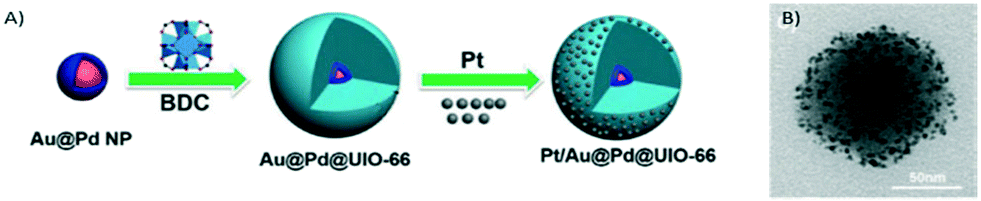 | ||
| Fig. 19 A) Synthetic route to produce the Pt/Au@Pd@UiO-66 composite. B) TEM image (reproduced from ref. 222 with permission from John Wiley and Sons, copyright 2021). | ||
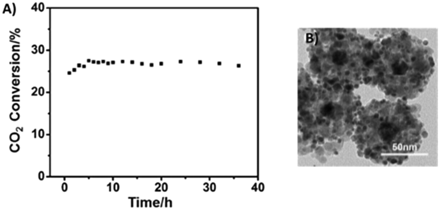
The as-obtained Pt/Au@Pd@UiO-66 composites were tested in the RWGS reaction using a continuous flow fixed bed reactor. At 300 °C, 2 MPa, a H2:CO2 molar ratio of 4:1, and a gas hourly space velocity of 24000 mL g−1 h−1, the CO2 conversion was 10% for this material. Elevated temperatures favoured the conversion of CO2 reaching 35.3% at 400 °C, but the selectivity to CO decreased with the increase of the temperature, mainly due to the heat absorbed by the endothermic RGWS reaction and the increased amount of CH4 derived from the unavoidable competitive methanation reaction. The stability performance of the Pt/Au@Pd@UiO-66 catalyst was excellent at 400 °C for over 30 h of continuous operation (Fig. 20). Pt nanoparticles still remained highly dispersed, and Au@Pd remained localized in the UIO-66 centres adopting a one-to-one fashion. Nevertheless, at 400 °C, the framework of UIO-66 collapsed. XRD analysis showed that UIO-66 had turned into ZrO2, and the aggregation of Pt led to clusters of ca. 5.9 nm on the oxide surface. This particle size was still small, so the catalyst maintained an excellent catalytic performance. The bimetal core Au@Pd displayed a robust structure resulting in the observed outstanding stability for continuous RWGS runs.
 | ||
| Fig. 20 A) RWGS reaction stability test at 400 °C and B) TEM image after catalysis at a temperature of 400 °C of the Pt/Au@Pd@UiO-66 catalyst (reproduced from ref. 222 with permission from John Wiley and Sons, copyright 2021). | ||
The relatively low thermal stability of MOFs could in principle be a drawback for the RWGS given the exothermic nature of the reaction requiring high temperatures to achieve high CO2 conversion levels. Nevertheless, the outstanding chemical and structural features of MOFs might outbalance this disadvantage since as demonstrated by Zheng and co-workers, a low-temperature RWGS catalyst can be designed based on a metal-doped MOF structure.222 As mentioned above implementation of low-temperature RWGS catalysts represents a step ahead on this technology if a downstream process such as FTS is envisaged to close the CO2 to fuel cycle. Herein MOFs present unique advantages, and their study deserves further attention.
Within the low-temperature RWGS contact, Gutterød et al. conducted CO2 hydrogenation over Pt-containing UiO-67 Zr-MOFs at low-temperatures, 220–280 °C, and ambient pressure.223 For this catalyst, Pt was introduced into the UiO-67 Zr-MOF framework by grafting it to a bipyridine-based linker, which constituted 5% of the framework linkers. Pt nanoparticles were obtained by pre-activation in a H2/Ar flow at 350 °C. It was evidenced that the UiO-67 Zr-MOF framework was stable during all treatments.
Experimental results showed that the CO2 conversion was positively correlated with the degree of Pt reduction over the MOF (Fig. 21). A CO selectivity above 90% was obtained under all tested conditions, a highly commendable achievement given that in the low temperature range CH4 is the preferred product according purely to thermodynamics.224 The authors observed a low reaction order in pH2 and pCO2, suggesting high coverage of the active site(s). Finally they compared the UiO-67–Pt catalysts with a conventional Pt/SiO2 catalyst showing very similar activation energy, with Eapp = 50 ± 3 kJ mol−1 suggesting that CO2 hydrogenation follows the same mechanism over the two materials.
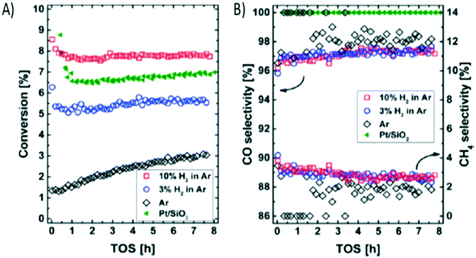 | ||
| Fig. 21 A) Conversion (%) versus time on stream (hours) observed for UiO-67–Pt-PSF(M) under reference conditions after pre-activation at 350 °C (1 h) in a flow of Ar with 0, 3, and 10% H2. B) CO and CH4 selectivities. The conversion and CO selectivity observed for a reference material, Pt/SiO2, is marked with green tilted triangles (reproduced from ref. 223 with permission from the American Chemical Society, copyright 2021). | ||
The use of MOFs as precursors of metal catalysts is another well-established field of research that is worth exploring for the preparation of highly dispersed supported active phases for the RWGS reaction. MOF derivatives, namely, metal oxide/carbon composites, tend to display enhanced catalytic activity and stability.225,226 This customised transformation of MOFs into high performance catalysts combines crystal engineering techniques while meeting the requirements from a chemical engineering perspective.
In a nutshell, the process consists of carefully controlled MOF thermal decomposition. During the thermal treatment, the metal ions present in the MOFs are transformed into metallic or metal oxide nanoparticles, and the organic linkers form carbonaceous structures that can act as supports facilitating the active phase dispersion.
In a recent proof-of-concept example, Ronda-Lloret et al. used a copper-based MOF as a metallic precursor and CeO2 as a final support/promoter to prepare a stable and active CuOx/CeO2 catalyst for the RWGS reaction (Fig. 22).227 In this work, a Cu-MOF (Basolite® C300) was impregnated with a ceria precursor and then pyrolyzed using different conditions and procedures. An oxidative atmosphere keeps copper oxidized during the decomposition and prevents active phase sintering. The presence of air in the decomposition induces the formation of copper oxide species, which have been demonstrated to be more resistant to sintering than metallic copper, thus favouring the interaction with the CeO2 support. Herein the authors found that the pyrolysis method determined the dispersion of the oxidized copper species on the ceria surface, which, in turn, controls the catalytic activity and selectivity of these MOF-derived catalysts in the RWGS reaction.
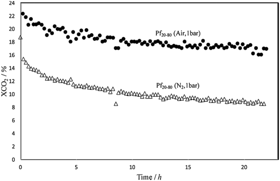 | ||
| Fig. 22 Comparison of the catalytic performance of the samples Pf20–80 (air, 1 bar) and Pf20–80 (N2, 1 bar) in RGWS (samples prepared by fast pyrolysis, Pf, with a molar ratio of 20Cu:80Ce) (reproduced from ref. 227 with permission from Elsevier, copyright 2021). | ||
Well-established industrial catalysts such as the Cu–Zn combination which is widely applied in methanol synthesis and industrial WGS reactions can also be re-engineered using MOFs as precursors. Zhang et al. and co-workers designed Cu/Zn nanoparticles in a carbon matrix material following this approach.228 In this work, Zn-doped Cu–BTC was pyrolyzed at 500 °C under an argon atmosphere. The encapsulation of the obtained Cu/Zn NPs in the porous carbon matrix protected the NPs from aggregation and sintering, leading to superior stability of the catalysts in the RWGS reaction. Furthermore, enhanced synergistic effects between Cu and Zn were achieved increasing the catalytic activity due to the well mixed Cu and Zn from pyrolysis. Additionally, the authors carried out a study of the dependence of the catalytic activity on the pellet size, which revealed the importance of fine-tuning the crystal sizes of the pyrolysis precursors, which allows eliminating an additional step of catalyst forming. The highest CO2 conversion (5%) and CO selectivity (100%) were exhibited by a Cu/Zn@C sample with a submillimeter-size at 500 °C and 1 bar (H2:CO2 = 3:1). Additionally, the catalyst remained stable and active for over 20 hours.
4.3. Dry reforming of methane (DRM)
Research on catalytic carbon dioxide reforming of methane by MOF-based materials has only just begun, and hence the literature in this area is scarce. Compared with other reference catalytic materials, such as metal oxides, zeolites, metal alloys, etc., there are still obvious gaps in stability and activity for MOF-based catalysts in this direct gas phase CO2 conversion reaction. However, from the existing reports, the prospects are very promising.Considering the thermal conditions of DRM (>600 °C), MOFs with low thermal stability (<400 °C) rapidly degrade, resulting in a structure collapse. Hence the way to use MOFs is as precursors of highly active catalysts in the DRM reaction.
This very strategy was successfully utilised by Karam et al. who utilised an Al-containing MIL-53 metal–organic framework with a very high surface area (SBET = 1130 m2 g−1) as a sacrificial template to prepare a nickel-alumina-based catalyst (Ni0AlMIL).229 After the calcination procedure, a porous uniform spinel phase with Ni nanoparticles embedded in the Al2O3-based matrix was obtained. This led after reduction to a porous lamellar γ-Al2O3 material with small Ni0 nanoparticles homogeneously dispersed and stabilized within the support. This MOF as a sacrificial framework provided materials with a higher surface area than those generally encountered in the domain, and the interlamellar spaces provided additional stabilization to the confined nickel nanoparticles, which in turn inhibited carbon nanotube formation during the reaction.
The Ni/AlMIL catalyst demonstrated a superior performance (CH4 and CO2 conversion) over a benchmark catalyst in the whole studied temperature range (Fig. 23). As for the H2:CO molar ratio, values for Ni0/Al (conventional γ-alumina) are always lower than the thermodynamic threshold (which is 1.0 due to the nature of the reaction) primarily due to the competition with the RWGS reaction. Interestingly such a H2/CO ratio becomes closer to 1 for Ni0/AlMIL, indicating a superior selectivity to the targeted reaction.
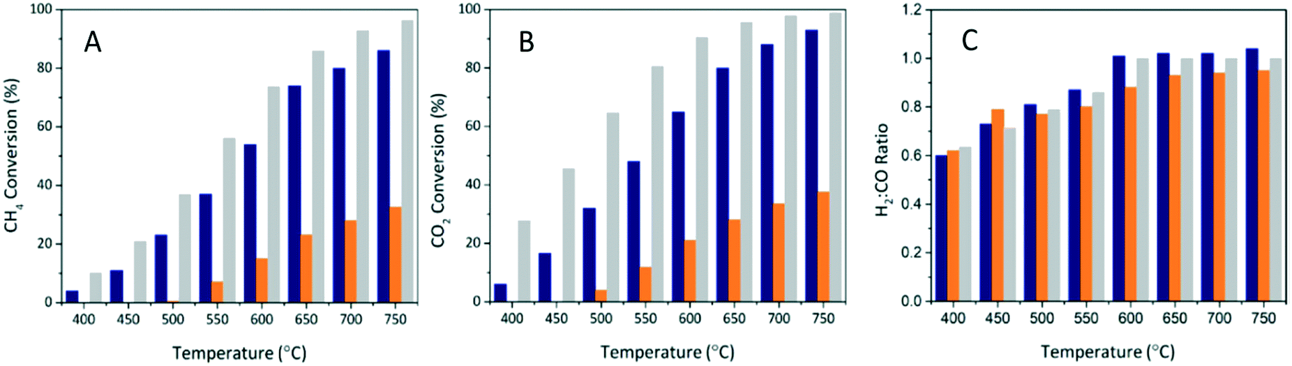 | ||
| Fig. 23 (A) CH4, (B) CO2 conversions, and (C) H2:CO product ratio during DRM at 400 °C to 750 °C over in situ reduced (800 °C/2 h): (blue) Ni0AlMIL and (orange) Ni0/Al (conventional γ-alumina). Grey columns are the calculated values at the thermodynamic equilibrium (reproduced from ref. 229 with permission from John Wiley and Sons, copyright 2021). | ||
Furthermore, this material showed outstanding catalytic stability after 100 h of reaction with limited occurrence of side reactions (Fig. 24).
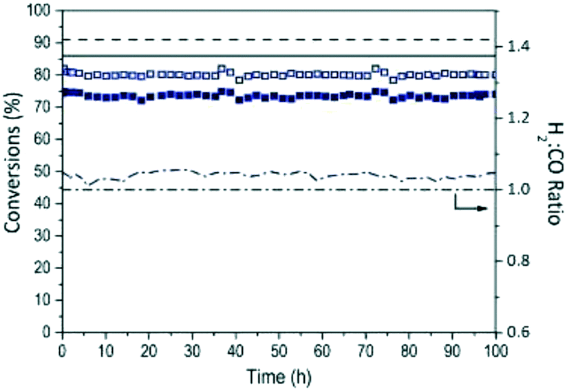 | ||
| Fig. 24 CO2 (filled squares) and CH4 (empty squares) conversions as well as H2:CO ratios (dash-dotted line) measured during 100 h of reaction for Ni0/AlMIL (the black dash-dotted line represents H2:CO = 1). Black continuous and dashed lines are the calculated values at the thermodynamic equilibrium for CH4 and CO2 conversions, respectively (reproduced from ref. 229 with permission from John Wiley and Sons, copyright 2021). | ||
Following a similar MOF templating strategy, our team recently reported the synthesis of mesoporous ZnO/Ni@m-SiO2 yolk–shell particles using a ZIF-8 MOF as a structural template.178 Briefly ZIF-8 was impregnated with a Ni precursor to form the core of the yolk–shell particles (Fig. 25). In this novel system, Ni/ZnO was selected as active sites constituting the yolk structure while porous silica was selected as the shell material. The advantages of these configurations are two-fold: (i) the shell acts as a barrier to prevent the blocking of the active sites through coke formation and (ii) the confinement effect ascribed to the encapsulation of the active centres prevents Ni sintering. In this seminal work we demonstrated the superiority of Ni based yolk–shell catalysts over standard Ni catalysts which are traditionally used in reforming units.
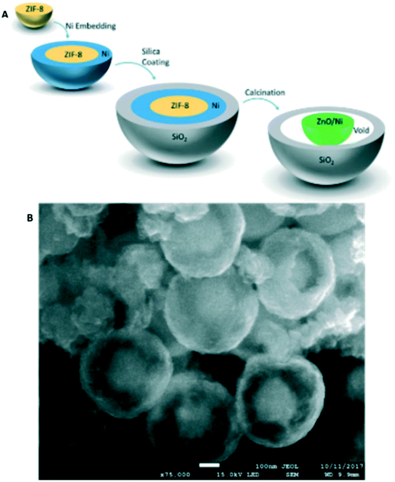 | ||
| Fig. 25 A) Schematic illustration of the synthesis procedure of yolk–shell catalysts. B) SEM image of the resultant ZnO/Ni@m-SiO2 yolk–shell particles, confirming successful encapsulation (reproduced from ref. 178 with permission from the Royal Society of Chemistry, copyright 2021). | ||
Perhaps more interestingly, a recent study reports a MOF material that directly serves as a chemically and thermally stable support in a particular case. R. Vakili et al. accomplished plasma-assisted dry reforming over a PtNP@UiO-67 catalyst (Fig. 26).230 The authors were able to break through the thermodynamic limit of the DRM by the energetic electron activation of reactant molecules rather than the traditional thermal activation. The highly porous UiO-67 (>2000 m2 g−1) was stable under plasma conditions showing no significant changes in its properties under conditions of different treatment times, discharge powers and gases. Furthermore, this MOF favored the dispersion of fine Pt particles. It has to be highlighted that the UiO-67 MOF facilitated the plasma formation and surface discharges in the discharge zone, coupling with the Pt particles to enhance the CH4 and CO2 conversion and syngas production due to the presence of surface reactions (Fig. 27).
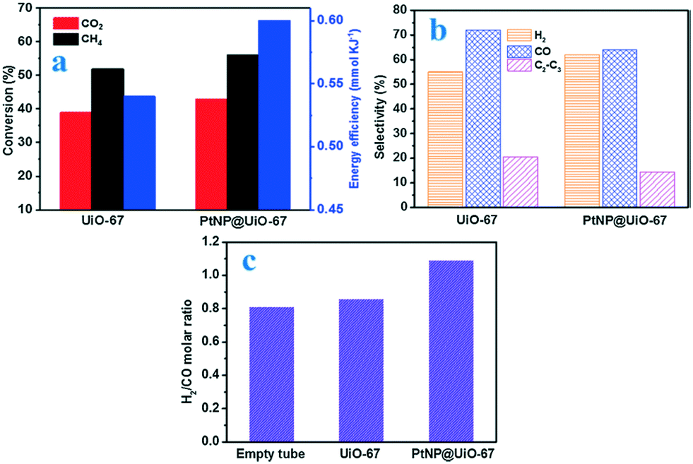 | ||
| Fig. 26 Effect of different catalysts on (a) conversions and energy efficiency, (b) H2/CO molar ratio and (c) selectivities to CO, H2 and hydrocarbons during the plasma assisted catalytic DRM (at a power of 11 W, a feed flow rate of 100 ml min−1 and CH4/CO2 molar ratio) (reproduced from ref. 230 with permission from Elsevier, copyright 2021). | ||
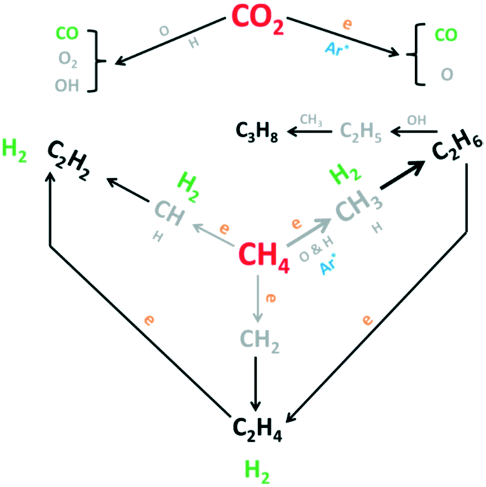 | ||
| Fig. 27 Main reaction pathways in plasma-assisted catalytic DRM (reproduced from ref. 230 with permission from Elsevier, copyright 2021). | ||
5. Concluding remarks and future perspectives
CO2 capture and conversion technologies rely on highly effective materials whose chemistry and engineering aspects must be finely customized to maximise the overall process performance. In this scenario, MOF materials emerge as revolutionary systems with unique features opening new research avenues for both CO2 capture and catalytic CO2 conversion. A great deal of work has been done so far by the chemistry and engineering communities resulting in promising breakthroughs in terms of CO2 capture capacity of custom-made MOFs when compared to the state-of-the-art materials. Herein aspects such as the synthesis method choice, the addition of promoters and careful control of the acid-based properties of the MOFs are crucial. Also, engineering aspects such as cyclability, regeneration and isosteric heat must be considered to fully describe the behaviour of a MOF for CO2 capture applications. Support from operando studies is deemed fundamental to discern the system dynamics during CO2 capture and hence to evaluate a rational design of high performance MOFs.As for the gas phase catalytic CO2 conversion, the results reported so far are certainly encouraging pointing a bright future for MOFs in core processes such as CO2 methanation, RWGS and DRM reactions. MOFs benefit from the confinement effect preventing the occurrence of frequent problems in heterogeneous catalysis such as carbon poisoning and metallic particle sintering. In addition, their framework allows outstanding active phase dispersion favoring high CO2 conversion levels outperforming standard catalysts for these reactions.
Besides the successful results, we have identified some gaps and challenges that require further attention if real application is envisaged. The utilization of realistic or surrogate flue gas streams for both CO2 capture and conversion is greatly lacking in the open literature. The presence of water, nitrogen, and sulphur oxides among other impurities may jeopardize the adsorption and catalytic features, and they must be studied to seriously consider MOFs for commercial applications in CO2 capture/upgrading processes. When it comes to catalysis and endothermic processes such as DRM, the thermal stability of MOFs imposes a challenge which should be overcome. Despite these difficulties, MOFs and CO2 conversion/scrubbing processes seem to share a common destiny, and there is no doubt that this family of unique materials is meant to play a crucial role in the implementation of disruptive low-carbon technologies to combat global warming.
List of acronyms and abbreviations
| aTZ | (1H-1,2,4-Triazol-3-yl)amide |
| bbIm | 5(6)-Bromobenzimidazole |
| BDC | 1,4-Benzenedicarboxylate |
| bIM | Benzimidazole |
| BPDC | Biphenyl-1,4-dicarboxylate |
| BPEB | 1,4-Bis(1H-pyrazol-4-ylethynyl)benzene |
| BPTC | 3,3′,5,5′-Biphenyltetracarboxylate |
| bpy | 2,2′-Bipyridine |
| brbIm | 6-Bromobenzylimidazole |
| BTB | 1,3,5-Tris(4-carboxyphenyl)benzene |
| BTC | Benzene-1,3,5-tricarboxylate |
| CALF-33 | [Cu3(L1-Et2H)2]n L1 = 1,3,5-tris(4-bromophenyl) benzene |
| cbIm | 5(6)-Chlorobenzimidazole |
| CCS | CO2 capture and storage |
| CCU | Carbon dioxide capture and utilisation |
| cnIm | 4-Cyanoimidazole |
| CPO | Coordination polymer of Oslo |
| DMF | N,N-Dimethyl formamide |
| DOBCO | 2,5-Dihydroxyterephthalic acid |
| EDS | 1,2-Ethanedisulfonate |
| HKUST | Hong Kong University of Science and Tech. |
| HKUST-1 | [Cu3(btc)2(H2O)3] |
| HPDC | 4,5,9,10-Tetrahydropyrene-2,7-dicarboxylate |
| HT | High-throughput |
| IRMOF | Isoreticular MOF |
| IRMOF-1 | Zn4O(BDC)3 |
| IRMOF-11 | Zn4O(HPDC)3 |
| IRMOF-3 | [Zn4O(NH2-BDC)3] |
| IRMOF-6 | Zn4O(cyclobutyl-BDC)3 |
| IRMOF-74-III | [Mg2(DH3PhDC)] |
| JUC | Jilin University China |
| JUC-150 | [Ni2(L-asp)2(pz)] |
| L-asp | L-aspartic acid |
| LIMF-26 | Fe3(TCDC)3(H2O)3 |
| mbIm | 5(6)-Methylbenzimidazole |
| M-CPO-27 | [M2(dobdc)(H2O)2] (M = Mg2+, Ni2+, Co2+, Zn2+) |
| MEA | Monoethanolamide |
| MeIM | Methyl-imidazole |
| MIL | Matériaux de l'Institut Lavoisier |
| MIL-100 | Fe3O(H2O)2F{C6H3(CO2)3}2·nH2O (n ≈ 14.5) |
| MIL-101 | Cr3F(H2O)2O(BDC)3·nH2O (n ≈ 25) |
| MIL-96 | Al12O(OH)18(H2O)3(Al2(OH)4)[btc]6·24H2O |
| MOF | Metal–organic framework |
| MOF-177 | [Zn4O(BTB)2] |
| MOF-2 | Zn(BDC)(DMF)(H2O) |
| MOF-5 | [Zn4O(BDC)3] |
| MOF-505 | [Cu2(bptc)(H2O)2(DMF)3(H2O)] |
| MUF | Massey University Framework |
| MUF-15 | [Fe2(O2)(dobdc)] |
| nbIm | 5-Nitrobenzimidazole |
| nbIM | Nitro-benzene imidazole |
| NH2-MIL-125 | [Ti8O8(OH)4(NH2-BDC)6] |
| NH2-MIL-53 | [Al(OH)(NH2-BDC)]n |
| NH2–UiO-66 | [Zr6O4(OH)4(NH2-BDC)6] |
| nIm | 2-Nitroimidazole |
| nIM | 5-Nitroimidazole |
| NOTT-202a | (Me2NH2)1.75[In(L)]1.75(DMF)12(H2O)10 (H4L = biphenyl-3,30,5,50-tetra-(phenyl-4-carboxylic acid)) |
| NU-100 | Cu3(TTEI) |
| PCN | Porous coordination network |
| PCN-61 | Cu3(H2O)3(btei) |
| PCN-66 | Cu3(H2O)3(ntei) |
| PCN-68 | Cu3(H2O)3(ptei) |
| PSF | Poly(bisphenol-A sulfone) |
| PVDF | Polyvinylidene fluoride |
| pz | Pyrazine |
| SBU | Secondary building unit |
| SNU | Seoul National University |
| SNU-100 | [Zn3(TCPT)2(HCOO)][NH2(CH3)2] |
| TCDC | 2,3,5,6-Tetrachloride terephthalate |
| TCPT | 2,4,6-Tris-(4-carboxy-phenoxy)-1,3,5-triazine |
| TMOF-1 | [Cu(4,40-bpy)2(EDS)]n |
| TZ | 3,5-Bis(trifluoromethyl)-1,2,4-triazolate |
| UiO | Universitetet i Oslo |
| UiO-66 | [Zr6O4(OH)4(BDC)6] |
| UiO-67 | [Zr6O4(OH)4(BPDC)6] |
| ZIF | Zeolitic imidazolate framework |
| ZIF-300 | Zn(2-mIm)0.86(bbIm)1.14 |
| ZIF-301 | Zn(2-mIm)0.94(cbIm)1.06 |
| ZIF-302 | Zn(2-mIm)0.67(mbIm)1.33 |
| ZIF-68 | Zn(bIm)(nIm) |
| ZIF-69 | Zn(cbIm)(nIm) |
| ZIF-7 | Zn(bIM)2 |
| ZIF-70 | Zn(Im)1.13(nIm)0.87 |
| ZIF-78 | Zn(nbIm)(nIm) |
| ZIF-79 | Zn(mbIm)(nIm) |
| ZIF-8 | Zn(MeIM)2 |
| ZIF-81 | Zn(brbIm)(nIm) |
| ZIF-82 | Zn(cnIm)(nIm) |
Author contributions
The authors equally contributed to this work.Conflicts of interest
There are no conflicts to declare.Acknowledgements
Financial support for this work was provided by the Spanish Ministry of Science and Spanish Ministry of Science and Innovation through the project RYC2018-024387-I as well as the project PID2019-108502RJ-I00. This work was also partially funded by the University of Seville via the VI PPIT grant scheme for talented researchers.References
- J. C. M. Farla, C. A. Hendriks and K. Blok, Clim. Change, 1995, 29, 439–461 CrossRef CAS
.
- G. Cui, J. Wang and S. Zhang, Chem. Soc. Rev., 2016, 45, 4307–4339 RSC
- S. Wang, S. Yan, X. Ma and J. Gong, Energy Environ. Sci., 2011, 4, 3805 RSC
- M. K. Mondal, H. K. Balsora and P. Varshney, Energy, 2012, 46, 431–441 CrossRef CAS
- A. Corma, H. García and F. X. Llabrés i Xamena, Chem. Rev., 2010, 110, 4606–4655 CrossRef CAS PubMed
- J. L. C. Rowsell and O. M. Yaghi, Microporous Mesoporous Mater., 2004, 73, 3–14 CrossRef CAS
- S. S. Kaye, A. Dailly, O. M. Yaghi and J. R. Long, J. Am. Chem. Soc., 2007, 129, 14176–14177 CrossRef CAS PubMed
-
F. X. Llabrés i Xamena and J. Gascon, in Metal Organic Frameworks as Heterogeneous Catalysts, 2001, pp. 1–5 Search PubMed
- H.-C. Zhou, J. R. Long and O. M. Yaghi, Chem. Rev., 2012, 112, 673–674 CrossRef CAS PubMed
- Q. Wang, J. Bai, Z. Lu, Y. Pan and X. You, Chem. Commun., 2016, 52, 443–452 RSC
- K. Eum, K. C. Jayachandrababu, F. Rashidi, K. Zhang, J. Leisen, S. Graham, R. P. Lively, R. R. Chance, D. S. Sholl, C. W. Jones and S. Nair, J. Am. Chem. Soc., 2015, 137, 4191–4197 CrossRef CAS PubMed
- W.-Y. Gao, Y. Chen, Y. Niu, K. Williams, L. Cash, P. J. Perez, L. Wojtas, J. Cai, Y.-S. Chen and S. Ma, Angew. Chem., Int. Ed., 2014, 53, 2615–2619 CrossRef CAS PubMed
- J. Yu, L.-H. Xie, J.-R. Li, Y. Ma, J. M. Seminario and P. B. Balbuena, Chem. Rev., 2017, 117, 9674–9754 CrossRef CAS PubMed
- A. A. Olajire, Energy, 2010, 35, 2610–2628 CrossRef CAS
- A. Rabenau, Angew. Chem., Int. Ed. Engl., 1985, 24, 1026–1040 CrossRef
- N. Stock and S. Biswas, Chem. Rev., 2012, 112, 933–969 CrossRef CAS PubMed
- R. Banerjee, A. Phan, B. Wang, C. Knobler, H. Furukawa, M. O'Keeffe and O. M. Yaghi, Science, 2008, 319, 939–943 CrossRef CAS PubMed
- P. Küsgens, M. Rose, I. Senkovska, H. Fröde, A. Henschel, S. Siegle and S. Kaskel, Microporous Mesoporous Mater., 2009, 120, 325–330 CrossRef
- S. J. Garibay and S. M. Cohen, Chem. Commun., 2010, 46, 7700 RSC
- X. Zhu, B. Li, J. Yang, Y. Li, W. Zhao, J. Shi and J. Gu, ACS Appl. Mater. Interfaces, 2015, 7, 223–231 CrossRef CAS PubMed
- S. H. Jhung, J. H. Lee and J. S. Chang, Bull. Korean Chem. Soc., 2005, 26, 880–881 CrossRef CAS
- R. Ameloot, L. Stappers, J. Fransaer, L. Alaerts, B. F. Sels and D. E. De Vos, Chem. Mater., 2009, 21, 2580–2582 CrossRef CAS
- T. Friščić, J. Mater. Chem., 2010, 20, 7599 RSC
- S. L. James, C. J. Adams, C. Bolm, D. Braga, P. Collier, T. Friščić, F. Grepioni, K. D. M. Harris, G. Hyett, W. Jones, A. Krebs, J. Mack, L. Maini, A. G. Orpen, I. P. Parkin, W. C. Shearouse, J. W. Steed and D. C. Waddell, Chem. Soc. Rev., 2012, 41, 413–447 RSC
- D. Braga and F. Grepioni, Chem. Commun., 2005, 3635 RSC
- L.-G. Qiu, Z.-Q. Li, Y. Wu, W. Wang, T. Xu and X. Jiang, Chem. Commun., 2008, 3642 RSC
- B. Rungtaweevoranit, C. S. Diercks, M. J. Kalmutzki and O. M. Yaghi, Faraday Discuss., 2017, 201, 9–45 RSC
- M. Ding, R. W. Flaig, H.-L. Jiang and O. M. Yaghi, Chem. Soc. Rev., 2019, 48, 2783–2828 RSC
- G. T. Rochelle, Science, 2009, 325, 1652–1654 CrossRef CAS PubMed
- L.-M. Dion, M. Lefsrud and V. Orsat, Biomass Bioenergy, 2011, 35, 3422–3432 CrossRef CAS
- V. Bon, I. Senkovska, M. S. Weiss and S. Kaskel, CrystEngComm, 2013, 15, 9572 RSC
- F. Drache, V. Bon, I. Senkovska, C. Marschelke, A. Synytska and S. Kaskel, Inorg. Chem., 2016, 55, 7206–7213 CrossRef CAS PubMed
- Z. Kang, M. Xue, L. Fan, L. Huang, L. Guo, G. Wei, B. Chen and S. Qiu, Energy Environ. Sci., 2014, 7, 4053–4060 RSC
- Y.-Q. Lan, S.-L. Li, H.-L. Jiang and Q. Xu, Chem. – Eur. J., 2012, 18, 8076–8083 CrossRef CAS PubMed
- C. A. Trickett, A. Helal, B. A. Al-Maythalony, Z. H. Yamani, K. E. Cordova and O. M. Yaghi, Nat. Rev. Mater., 2017, 2, 17045 CrossRef CAS
- Y. Lin, C. Kong, Q. Zhang and L. Chen, Adv. Energy Mater., 2017, 7, 1601296 CrossRef
- K. C. Stylianou and W. L. Queen, CHIMIA International Journal for Chemistry, 2015, 69, 274–283 CrossRef CAS PubMed
- D. Andirova, C. F. Cogswell, Y. Lei and S. Choi, Microporous Mesoporous Mater., 2016, 219, 276–305 CrossRef CAS
- A. R. Millward and O. M. Yaghi, J. Am. Chem. Soc., 2005, 127, 17998–17999 CrossRef CAS PubMed
- H. W. B. Teo, A. Chakraborty and S. Kayal, Appl. Therm. Eng., 2017, 110, 891–900 CrossRef CAS
- J. Li, C. Zhu, Z. Qiao, X. Chen, W. Wei, H. Ji and K. Sohlberg, Appl. Surf. Sci., 2016, 385, 578–586 CrossRef CAS
- W. L. Queen, M. R. Hudson, E. D. Bloch, J. A. Mason, M. I. Gonzalez, J. S. Lee, D. Gygi, J. D. Howe, K. Lee, T. A. Darwish, M. James, V. K. Peterson, S. J. Teat, B. Smit, J. B. Neaton, J. R. Long and C. M. Brown, Chem. Sci., 2014, 5, 4569–4581 RSC
- X. Kong, E. Scott, W. Ding, J. A. Mason, J. R. Long and J. A. Reimer, J. Am. Chem. Soc., 2012, 134, 14341–14344 CrossRef CAS PubMed
- C.-X. Chen, S.-P. Zheng, Z.-W. Wei, C.-C. Cao, H.-P. Wang, D. Wang, J.-J. Jiang, D. Fenske and C.-Y. Su, Chem. – Eur. J., 2017, 23, 4060–4064 CrossRef CAS PubMed
- J. A. Mason, T. M. McDonald, T.-H. Bae, J. E. Bachman, K. Sumida, J. J. Dutton, S. S. Kaye and J. R. Long, J. Am. Chem. Soc., 2015, 137, 4787–4803 CrossRef CAS PubMed
- O. K. Farha, A. Özgür Yazaydın, I. Eryazici, C. D. Malliakas, B. G. Hauser, M. G. Kanatzidis, S. T. Nguyen, R. Q. Snurr and J. T. Hupp, Nat. Chem., 2010, 2, 944–948 CrossRef CAS PubMed
- D. Yuan, D. Zhao, D. Sun and H.-C. Zhou, Angew. Chem., Int. Ed., 2010, 49, 5357–5361 CrossRef CAS PubMed
- T. Loiseau, L. Lecroq, C. Volkringer, J. Marrot, G. Férey, M. Haouas, F. Taulelle, S. Bourrelly, P. L. Llewellyn and M. Latroche, J. Am. Chem. Soc., 2006, 128, 10223–10230 CrossRef CAS PubMed
- Z. Guo, H. Wu, G. Srinivas, Y. Zhou, S. Xiang, Z. Chen, Y. Yang, W. Zhou, M. O'Keeffe and B. Chen, Angew. Chem., Int. Ed., 2011, 50, 3178–3181 CrossRef CAS PubMed
- S. Surblé, F. Millange, C. Serre, T. Düren, M. Latroche, S. Bourrelly, P. L. L. Llewellyn and G. Férey, J. Am. Chem. Soc., 2006, 128, 14889–14896 CrossRef PubMed
- N. MacDowell, N. Florin, A. Buchard, J. Hallett, A. Galindo, G. Jackson, C. S. Adjiman, C. K. Williams, N. Shah and P. Fennell, Energy Environ. Sci., 2010, 3, 1645 RSC
- H. R. Abid, J. Shang, H.-M. Ang and S. Wang, Int. J. Smart Nano Mater., 2013, 4, 72–82 CrossRef CAS
- Q. Yang, A. D. Wiersum, P. L. Llewellyn, V. Guillerm, C. Serre and G. Maurin, Chem. Commun., 2011, 47, 9603 RSC
- P.-Q. Liao, X.-W. Chen, S.-Y. Liu, X.-Y. Li, Y.-T. Xu, M. Tang, Z. Rui, H. Ji, J.-P. Zhang and X.-M. Chen, Chem. Sci., 2016, 7, 6528–6533 RSC
- S. Couck, J. F. M. Denayer, G. V. Baron, T. Rémy, J. Gascon and F. Kapteijn, J. Am. Chem. Soc., 2009, 131, 6326–6327 CrossRef CAS PubMed
- Y.-S. Bae, O. K. Farha, A. M. Spokoyny, C. A. Mirkin, J. T. Hupp and R. Q. Snurr, Chem. Commun., 2008, 4135 RSC
- S.-N. Kim, J. Kim, H.-Y. Kim, H.-Y. Cho and W.-S. Ahn, Catal. Today, 2013, 204, 85–93 CrossRef CAS
- X. Si, C. Jiao, F. Li, J. Zhang, S. Wang, S. Liu, Z. Li, L. Sun, F. Xu, Z. Gabelica and C. Schick, Energy Environ. Sci., 2011, 4, 4522 RSC
- J. An, S. J. Geib and N. L. Rosi, J. Am. Chem. Soc., 2010, 132, 38–39 CrossRef CAS PubMed
- B. Li, Z. Zhang, Y. Li, K. Yao, Y. Zhu, Z. Deng, F. Yang, X. Zhou, G. Li, H. Wu, N. Nijem, Y. J. Chabal, Z. Lai, Y. Han, Z. Shi, S. Feng and J. Li, Angew. Chem., Int. Ed., 2012, 51, 1412–1415 CrossRef CAS PubMed
- T. M. McDonald, D. M. D'Alessandro, R. Krishna and J. R. Long, Chem. Sci., 2011, 2, 2022 RSC
- P.-Q. Liao, D.-D. Zhou, A.-X. Zhu, L. Jiang, R.-B. Lin, J.-P. Zhang and X.-M. Chen, J. Am. Chem. Soc., 2012, 134, 17380–17383 CrossRef CAS
- R. W. Flaig, T. M. Osborn Popp, A. M. Fracaroli, E. A. Kapustin, M. J. Kalmutzki, R. M. Altamimi, F. Fathieh, J. A. Reimer and O. M. Yaghi, J. Am. Chem. Soc., 2017, 139, 12125–12128 CrossRef CAS PubMed
- Z. Shi, Y. Tao, J. Wu, C. Zhang, H. He, L. Long, Y. Lee, T. Li and Y.-B. Zhang, J. Am. Chem. Soc., 2020, 142, 2750–2754 CrossRef CAS PubMed
- R. Banerjee, H. Furukawa, D. Britt, C. Knobler, M. O. Keeffe and O. M. Yaghi, J. Am. Chem. Soc., 2009, 131, 3875–3877 CrossRef CAS PubMed
- G. Zhang, G. Wei, Z. Liu, S. R. J. Oliver and H. Fei, Chem. Mater., 2016, 28, 6276–6281 CrossRef CAS
- O. T. Qazvini, L. K. Macreadie and S. G. Telfer, Chem. Mater., 2020, 32, 6744–6752 CrossRef CAS
- G. Chakraborty, P. Das and S. K. Mandal, ACS Appl. Mater. Interfaces, 2020, 12, 11724–11736 CrossRef CAS PubMed
- Q. Yang, S. Vaesen, F. Ragon, A. D. Wiersum, D. Wu, A. Lago, T. Devic, C. Martineau, F. Taulelle, P. L. Llewellyn, H. Jobic, C. Zhong, C. Serre, G. De Weireld and G. Maurin, Angew. Chem., Int. Ed., 2013, 52, 10316–10320 CrossRef CAS PubMed
- K. Uemura, R. Matsuda and S. Kitagawa, J. Solid State Chem., 2005, 178, 2420–2429 CrossRef CAS
- S. Bureekaew, S. Shimomura and S. Kitagawa, Sci. Technol. Adv. Mater., 2008, 9, 14108 CrossRef PubMed
- S. Horike, S. Shimomura and S. Kitagawa, Nat. Chem., 2009, 1, 695–704 CrossRef CAS PubMed
- A. Schneemann, V. Bon, I. Schwedler, I. Senkovska, S. Kaskel and R. A. Fischer, Chem. Soc. Rev., 2014, 43, 6062–6096 RSC
- S. Ehrling, M. Mendt, I. Senkovska, J. D. Evans, V. Bon, P. Petkov, C. Ehrling, F. Walenszus, A. Pöppl and S. Kaskel, Chem. Mater., 2020, 32, 5670–5681 CrossRef CAS
- Q. Dong, X. Zhang, S. Liu, R. Lin, Y. Guo, Y. Ma, A. Yonezu, R. Krishna, G. Liu, J. Duan, R. Matsuda, W. Jin and B. Chen, Angew. Chem., Int. Ed., 2020, 59, 22756–22762 CrossRef CAS PubMed
- S. Aguado, G. Bergeret, M. P. Titus, V. Moizan, C. Nieto-Draghi, N. Bats and D. Farrusseng, New J. Chem., 2011, 35, 546–550 RSC
- C. Cuadrado-Collados, J. Fernández-Català, F. Fauth, Y. Q. Cheng, L. L. Daemen, A. J. Ramirez-Cuesta and J. Silvestre-Albero, J. Mater. Chem. A, 2017, 5, 20938–20946 RSC
- J. van den Bergh, C. Gücüyener, E. A. Pidko, E. J. M. Hensen, J. Gascon and F. Kapteijn, Chem. – Eur. J., 2011, 17, 8832–8840 CrossRef CAS PubMed
- P. K. Thallapally, J. Tian, M. Radha Kishan, C. A. Fernandez, S. J. Dalgarno, P. B. McGrail, J. E. Warren and J. L. Atwood, J. Am. Chem. Soc., 2008, 130, 16842–16843 CrossRef CAS PubMed
- S. Yang, X. Lin, W. Lewis, M. Suyetin, E. Bichoutskaia, J. E. Parker, C. C. Tang, D. R. Allan, P. J. Rizkallah, P. Hubberstey, N. R. Champness, K. Mark Thomas, A. J. Blake and M. Schröder, Nat. Mater., 2012, 11, 710–716 CrossRef CAS PubMed
- B. Li and B. Chen, Sci. China: Chem., 2016, 59, 965–969 CrossRef CAS
- C. Wang, L. Li, J. G. Bell, X. Lv, S. Tang, X. Zhao and K. M. Thomas, Chem. Mater., 2015, 27, 1502–1516 CrossRef CAS
- A. C. Forse, K. A. Colwell, M. I. Gonzalez, S. Benders, R. M. Torres-Gavosto, B. Blümich, J. A. Reimer and J. R. Long, Chem. Mater., 2020, 32, 3570–3576 CrossRef CAS
- R. Zhang, J.-H. Huang, D.-X. Meng, F.-Y. Ge, L.-F. Wang, Y.-K. Xu, X.-G. Liu, M.-M. Meng, Z.-Z. Lu, H.-G. Zheng and W. Huang, Dalton Trans., 2020, 49, 5618–5624 RSC
- M. Eddaoudi, Science, 2002, 295, 469–472 CrossRef CAS PubMed
- H. Deng, S. Grunder, K. E. Cordova, C. Valente, H. Furukawa, M. Hmadeh, F. Gandara, A. C. Whalley, Z. Liu, S. Asahina, H. Kazumori, M. O'Keeffe, O. Terasaki, J. F. Stoddart and O. M. Yaghi, Science, 2012, 336, 1018–1023 CrossRef CAS PubMed
- L. Xie, M. Xu, X. Liu, M. Zhao and J. Li, Adv. Sci., 2020, 7, 1901758 CrossRef CAS PubMed
- C. Mottillo and T. Friščić, Angew. Chem., Int. Ed., 2014, 53, 7471–7474 CrossRef CAS PubMed
- A. C. Kizzie, A. G. Wong-Foy and A. J. Matzger, Langmuir, 2011, 27, 6368–6373 CrossRef CAS PubMed
- B. S. Gelfand, R. P. S. Huynh, R. K. Mah and G. K. H. Shimizu, Angew. Chem., Int. Ed., 2016, 55, 14614–14617 CrossRef CAS
- Y.-S. Bae, J. Liu, C. E. Wilmer, H. Sun, A. N. Dickey, M. B. Kim, A. I. Benin, R. R. Willis, D. Barpaga, M. D. LeVan and R. Q. Snurr, Chem. Commun., 2014, 50, 3296–3298 RSC
- N. Ding, H. Li, X. Feng, Q. Wang, S. Wang, L. Ma, J. Zhou and B. Wang, J. Am. Chem. Soc., 2016, 138, 10100–10103 CrossRef CAS PubMed
- W. Zhang, Y. Hu, J. Ge, H.-L. Jiang and S.-H. Yu, J. Am. Chem. Soc., 2014, 136, 16978–16981 CrossRef CAS PubMed
- M. Ding, X. Cai and H.-L. Jiang, Chem. Sci., 2019, 10, 10209–10230 RSC
- N. T. T. Nguyen, H. Furukawa, F. Gándara, H. T. Nguyen, K. E. Cordova and O. M. Yaghi, Angew. Chem., Int. Ed., 2014, 53, 10645–10648 CrossRef CAS PubMed
- M. Kalaj and S. M. Cohen, ACS Cent. Sci., 2020, 6, 1046–1057 CrossRef CAS PubMed
- Y.-S. Bae, O. K. Farha, J. T. Hupp and R. Q. Snurr, J. Mater. Chem., 2009, 19, 2131 RSC
- C. H. Lau, R. Babarao and M. R. Hill, Chem. Commun., 2013, 49, 3634 RSC
- A. Kronast, S. Eckstein, P. T. Altenbuchner, K. Hindelang, S. I. Vagin and B. Rieger, Chem. – Eur. J., 2016, 22, 12800–12807 CrossRef CAS
- C. Le Calvez, M. Zouboulaki, C. Petit, L. Peeva and N. Shirshova, RSC Adv., 2016, 6, 17314–17317 RSC
- M. Kalaj, K. C. Bentz, S. Ayala, J. M. Palomba, K. S. Barcus, Y. Katayama and S. M. Cohen, Chem. Rev., 2020, 120, 8267–8302 CrossRef CAS PubMed
- Y. Zhang, X. Feng, S. Yuan, J. Zhou and B. Wang, Inorg. Chem. Front., 2016, 3, 896–909 RSC
- J. C. Moreton, M. S. Denny and S. M. Cohen, Chem. Commun., 2016, 52, 14376–14379 RSC
- M. S. Denny and S. M. Cohen, Angew. Chem., Int. Ed., 2015, 54, 9029–9032 CrossRef CAS PubMed
- N. C. Su, D. T. Sun, C. M. Beavers, D. K. Britt, W. L. Queen and J. J. Urban, Energy Environ. Sci., 2016, 9, 922–931 RSC
- E. A. Feijani, H. Mahdavi and A. Tavasoli, Chem. Eng. Res. Des., 2015, 96, 87–102 CrossRef CAS
- S. Sircar, R. Mohr, C. Ristic and M. B. Rao, J. Phys. Chem. B, 1999, 103, 6539–6546 CrossRef CAS PubMed
- H. Pan, J. A. Ritter and P. B. Balbuena, Ind. Eng. Chem. Res., 1998, 37, 1159–1166 CrossRef CAS
- M. Dincă, A. Dailly, Y. Liu, C. M. Brown, D. A. Neumann and J. R. Long, J. Am. Chem. Soc., 2006, 128, 16876–16883 CrossRef PubMed
- J. An and N. L. Rosi, J. Am. Chem. Soc., 2010, 132, 5578–5579 CrossRef CAS PubMed
- T. Li and N. L. Rosi, Chem. Commun., 2013, 49, 11385 RSC
- H. J. Park and M. P. Suh, Chem. Sci., 2013, 4, 685–690 RSC
- A. Raksajati, M. T. Ho and D. E. Wiley, Ind. Eng. Chem. Res., 2013, 52, 16887–16901 CrossRef CAS
- P. Billemont, N. Heymans, P. Normand and G. De Weireld, Adsorption, 2017, 23, 225–237 CrossRef CAS
- A. L. Myers and J. M. Prausnitz, AIChE J., 1965, 11, 121–127 CrossRef CAS
- K. S. Walton and D. S. Sholl, AIChE J., 2015, 61, 2757–2762 CrossRef CAS
- Y.-S. Bae, K. L. Mulfort, H. Frost, P. Ryan, S. Punnathanam, L. J. Broadbelt, J. T. Hupp and R. Q. Snurr, Langmuir, 2008, 24, 8592–8598 CrossRef CAS PubMed
- F.-X. Coudert, C. Mellot-Draznieks, A. H. Fuchs and A. Boutin, J. Am. Chem. Soc., 2009, 131, 11329–11331 CrossRef CAS PubMed
- B. Liu and B. Smit, Langmuir, 2009, 25, 5918–5926 CrossRef CAS PubMed
- J. E. Bara, C. J. Gabriel, S. Lessmann, T. K. Carlisle, A. Finotello, D. L. Gin and R. D. Noble, Ind. Eng. Chem. Res., 2007, 46, 5380–5386 CrossRef CAS
- S. Farooq and D. M. Ruthven, AIChE J., 1991, 37, 299–301 CrossRef CAS
- S. Farooq, H. Qinglin and I. A. Karimi, Ind. Eng. Chem. Res., 2002, 41, 1098–1106 CrossRef CAS
- M. Khalighi, S. Farooq and I. A. Karimi, Ind. Eng. Chem. Res., 2012, 51, 10659–10670 CrossRef CAS
- Z. Hu, M. Khurana, Y. H. Seah, M. Zhang, Z. Guo and D. Zhao, Chem. Eng. Sci., 2015, 124, 61–69 CrossRef CAS
- L. Hamon, P. L. Llewellyn, T. Devic, A. Ghoufi, G. Clet, V. Guillerm, G. D. Pirngruber, G. Maurin, C. Serre, G. Driver, W. van Beek, E. Jolimaître, A. Vimont, M. Daturi and G. Férey, J. Am. Chem. Soc., 2009, 131, 17490–17499 CrossRef CAS PubMed
-
D. M. Ruthven, S. Farooq and K. S. Knaebel, Pressure Swing Adsorption, VCH Publishers, 1994 Search PubMed
- S. Xiang, Y. He, Z. Zhang, H. Wu, W. Zhou, R. Krishna and B. Chen, Nat. Commun., 2012, 3(1), 954 CrossRef PubMed
- N. Al-Janabi, P. Hill, L. Torrente-Murciano, A. Garforth, P. Gorgojo, F. Siperstein and X. Fan, Chem. Eng. J., 2015, 281, 669–677 CrossRef CAS
- Z. Hu, Y. Wang, S. Farooq and D. Zhao, AIChE J., 2017, 63, 4103–4114 CrossRef CAS
- K. Sumida, D. L. Rogow, J. A. Mason, T. M. McDonald, E. D. Bloch, Z. R. Herm, T.-H. Bae and J. R. Long, Chem. Rev., 2012, 112, 724–781 CrossRef CAS PubMed
- J. Canivet, A. Fateeva, Y. Guo, B. Coasne and D. Farrusseng, Chem. Soc. Rev., 2014, 43, 5594–5617 RSC
- H. Furukawa, F. Gándara, Y.-B. Zhang, J. Jiang, W. L. Queen, M. R. Hudson and O. M. Yaghi, J. Am. Chem. Soc., 2014, 136, 4369–4381 CrossRef CAS PubMed
- M. Khurana and S. Farooq, AIChE J., 2017, 63, 2987–2995 CrossRef CAS
- Z. Hu, Y. Wang, B. B. Shah and D. Zhao, Adv. Sustainable Syst., 2019, 3, 1800080 CrossRef
- Y. Wang, Z. Hu, T. Kundu, Y. Cheng, J. Dong, Y. Qian, L. Zhai and D. Zhao, ACS Sustainable Chem. Eng., 2018, 6, 11904–11912 CrossRef CAS
- P. J. Milner, J. D. Martell, R. L. Siegelman, D. Gygi, S. C. Weston and J. R. Long, Chem. Sci., 2018, 9, 160–174 RSC
- J.-H. Lee, R. L. Siegelman, L. Maserati, T. Rangel, B. A. Helms, J. R. Long and J. B. Neaton, Chem. Sci., 2018, 9, 5197–5206 RSC
-
M. E. Davis and R. J. Davis, Fundamentals of Chemical Reaction Engineering, Dover Publications, 2013 Search PubMed
- F. Stallmach and J. Kärger, Adsorption, 1999, 5, 117–133 CrossRef CAS
- Y. Wang and D. Zhao, Cryst. Growth Des., 2017, 17, 2291–2308 CrossRef CAS
- L. Li, J. G. Bell, S. Tang, X. Lv, C. Wang, Y. Xing, X. Zhao and K. M. Thomas, Chem. Mater., 2014, 26, 4679–4695 CrossRef CAS
- P. Nugent, Y. Belmabkhout, S. D. Burd, A. J. Cairns, R. Luebke, K. Forrest, T. Pham, S. Ma, B. Space, L. Wojtas, M. Eddaoudi and M. J. Zaworotko, Nature, 2013, 495, 80–84 CrossRef CAS PubMed
- C. Y. Lee, Y.-S. Bae, N. C. Jeong, O. K. Farha, A. A. Sarjeant, C. L. Stern, P. Nickias, R. Q. Snurr, J. T. Hupp and S. T. Nguyen, J. Am. Chem. Soc., 2011, 133, 5228–5231 CrossRef CAS PubMed
- K. Li, D. H. Olson, J. Seidel, T. J. Emge, H. Gong, H. Zeng and J. Li, J. Am. Chem. Soc., 2009, 131, 10368–10369 CrossRef CAS PubMed
- S. Tanaka, K. Fujita, Y. Miyake, M. Miyamoto, Y. Hasegawa, T. Makino, S. Van der Perre, J. C. S. Remi, T. Van Assche, G. V. Baron and J. F. M. Denayer, J. Phys. Chem. C, 2015, 119, 28430–28439 CrossRef CAS
- B. K. Sward and M. D. LeVan, Adsorption, 2003, 9, 37–54 CrossRef CAS
- T. M. Tovar, J. Zhao, W. T. Nunn, H. F. Barton, G. W. Peterson, G. N. Parsons and M. D. LeVan, J. Am. Chem. Soc., 2016, 138, 11449–11452 CrossRef CAS PubMed
- B. M. Connolly, D. G. Madden, A. E. H. Wheatley and D. Fairen-Jimenez, J. Am. Chem. Soc., 2020, 142, 8541–8549 CrossRef CAS PubMed
- B. M. Connolly, M. Aragones-Anglada, J. Gandara-Loe, N. A. Danaf, D. C. Lamb, J. P. Mehta, D. Vulpe, S. Wuttke, J. Silvestre-Albero, P. Z. Moghadam, A. E. H. Wheatley and D. Fairen-Jimenez, Nat. Commun., 2019, 10, 2345 CrossRef CAS PubMed
- S. Lawson, C. Griffin, K. Rapp, A. A. A. Rownaghi and F. Rezaei, Energy Fuels, 2019, 33, 2399–2407 CrossRef CAS
- J. M. Tuffnell, C. W. Ashling, J. Hou, S. Li, L. Longley, M. L. Ríos Gómez and T. D. Bennett, Chem. Commun., 2019, 55, 8705–8715 RSC
- A.-M. Banu, D. Friedrich, S. Brandani and T. Düren, Ind. Eng. Chem. Res., 2013, 52, 9946–9957 CrossRef CAS
- A. Samanta, A. Zhao, G. K. H. Shimizu, P. Sarkar and R. Gupta, Ind. Eng. Chem. Res., 2012, 51, 1438–1463 CrossRef CAS
- C. P. O'Brien, J. Membr. Sci., 2021, 619, 118751 CrossRef
- M. O. Guerrero-Pérez and M. A. Bañares, Catal. Today, 2006, 113, 48–57 CrossRef
- T. Hartman, R. G. Geitenbeek, C. S. Wondergem, W. van der Stam and B. M. Weckhuysen, ACS Nano, 2020, 14, 3725–3735 CrossRef CAS PubMed
- B. M. Weckhuysen, Phys. Chem. Chem. Phys., 2003, 5, 4351 RSC
- J.-D. Grunwaldt, J. B. Wagner and R. E. Dunin-Borkowski, ChemCatChem, 2013, 5, 62–80 CrossRef CAS
- V. Bon, E. Brunner, A. Pöppl and S. Kaskel, Adv. Funct. Mater., 2020, 30, 1907847 CrossRef CAS
- K. I. Hadjiivanov, D. A. Panayotov, M. Y. Mihaylov, E. Z. Ivanova, K. K. Chakarova, S. M. Andonova and N. L. Drenchev, Chem. Rev., 2021, 121(3), 1286–1424 CrossRef CAS PubMed
- Y. Fu, H. Guan, J. Yin and X. Kong, Coord. Chem. Rev., 2021, 427, 213563 CrossRef CAS
- T. L. Easun, F. Moreau, Y. Yan, S. Yang and M. Schröder, Chem. Soc. Rev., 2017, 46, 239–274 RSC
- L. Braglia, E. Borfecchia, L. Maddalena, S. Øien, K. A. Lomachenko, A. L. Bugaev, S. Bordiga, A. V. Soldatov, K. P. Lillerud and C. Lamberti, Catal. Today, 2017, 283, 89–103 CrossRef CAS
- M. A. Soldatov, A. Martini, A. L. Bugaev, I. Pankin, P. V. Medvedev, A. A. Guda, A. M. Aboraia, Y. S. Podkovyrina, A. P. Budnyk, A. A. Soldatov and C. Lamberti, Polyhedron, 2018, 155, 232–253 CrossRef CAS
- P. L. Llewellyn, S. Bourrelly, C. Vagner, N. Heymans, H. Leclerc, A. Ghoufi, P. Bazin, A. Vimont, M. Daturi, T. Devic, C. Serre, G. De Weireld and G. Maurin, J. Phys. Chem. C, 2013, 117, 962–970 CrossRef CAS
- Y. Lu, B. E. G. Lucier, Y. Zhang, P. Ren, A. Zheng and Y. Huang, Phys. Chem. Chem. Phys., 2017, 19, 6130–6141 RSC
- M. Mendt, B. Jee, N. Stock, T. Ahnfeldt, M. Hartmann, D. Himsl and A. Pöppl, J. Phys. Chem. C, 2010, 114, 19443–19451 CrossRef CAS
- M. Mendt, P. Vervoorts, A. Schneemann, R. A. Fischer and A. Pöppl, J. Phys. Chem. C, 2019, 123, 2940–2952 CrossRef CAS
- M. Du, L. Li, M. Li and R. Si, RSC Adv., 2016, 6, 62705–62716 RSC
- C. Giacobbe, E. Lavigna, A. Maspero and S. Galli, J. Mater. Chem.
A, 2017, 5, 16964–16975 RSC
- L. Wang, L. Wang, J. Zhang, X. Liu, H. Wang, W. Zhang, Q. Yang, J. Ma, X. Dong, S. J. Yoo, J.-G. Kim, X. Meng and F.-S. Xiao, Angew. Chem., Int. Ed., 2018, 57, 6104–6108 CrossRef CAS PubMed
- A. Ramirez, L. Gevers, A. Bavykina, S. Ould-Chikh and J. Gascon, ACS Catal., 2018, 8, 9174–9182 CrossRef CAS
- J. Wei, Q. Ge, R. Yao, Z. Wen, C. Fang, L. Guo, H. Xu and J. Sun, Nat. Commun., 2017, 8, 16170 CrossRef CAS PubMed
- L. Jiao, W. Yang, G. Wan, R. Zhang, X. Zheng, H. Zhou, S. Yu and H. Jiang, Angew. Chem., Int. Ed., 2020, 59, 20589–20595 CrossRef CAS PubMed
- Y. Gong, L. Jiao, Y. Qian, C. Pan, L. Zheng, X. Cai, B. Liu, S. Yu and H. Jiang, Angew. Chem., Int. Ed., 2020, 59, 2705–2709 CrossRef CAS PubMed
- T. Stroud, T. J. Smith, E. Le Saché, J. L. Santos, M. A. Centeno, H. Arellano-Garcia, J. A. Odriozola and T. R. Reina, Appl. Catal., B, 2018, 224, 125–135 CrossRef CAS
- L. Yang, L. Pastor-Pérez, S. Gu, A. Sepúlveda-Escribano and T. R. Reina, Appl. Catal., B, 2018, 232, 464–471 CrossRef CAS
- C.-A. H. Price, L. Pastor-Pérez, T. Ramirez Reina and J. Liu, React. Chem. Eng., 2018, 3, 433–436 RSC
- L. Pastor-Pérez, V. Patel, E. Le Saché and T. R. Reina, J. Energy Inst., 2020, 93, 415–424 CrossRef
- W.-G. Cui, G.-Y. Zhang, T.-L. Hu and X.-H. Bu, Coord. Chem. Rev., 2019, 387, 79–120 CrossRef CAS
- W. Xu, K. B. Thapa, Q. Ju, Z. Fang and W. Huang, Coord. Chem. Rev., 2018, 373, 199–232 CrossRef CAS
- L. Jiao, J. Y. R. Seow, W. S. Skinner, Z. U. Wang and H.-L. Jiang, Mater. Today, 2019, 27, 43–68 CrossRef CAS
- T. Kitao, Y. Zhang, S. Kitagawa, B. Wang and T. Uemura, Chem. Soc. Rev., 2017, 46, 3108–3133 RSC
- W. J. Lee, C. Li, H. Prajitno, J. Yoo, J. Patel, Y. Yang and S. Lim, Catal. Today DOI:10.1016/j.cattod.2020.02.017
- C. Vogt, M. Monai, G. J. Kramer and B. M. Weckhuysen, Nat. Catal., 2019, 2, 188–197 CrossRef CAS
- J. B. Cohen and H. D. Dakin, J. Chem. Soc., Trans., 1902, 81, 1324–1344 RSC
- Y. Zheng, H. Liu and Y. Zhang, ChemSusChem, 2020, 13, 6090–6123 CAS
- B. Miao, S. S. K. Ma, X. Wang, H. Su and S. H. Chan, Catal. Sci. Technol., 2016, 6, 4048–4058 RSC
- K. Stangeland, D. Kalai, H. Li and Z. Yu, Energy Procedia, 2017, 105, 2022–2027 CrossRef CAS
- W. Li, H. Wang, X. Jiang, J. Zhu, Z. Liu, X. Guo and C. Song, RSC Adv., 2018, 8, 7651–7669 RSC
- L. Shen, J. Xu, M. Zhu and Y.-F. Han, ACS Catal., 2020, 10, 14581–14591 CrossRef CAS
- J. Ashok, S. Pati, P. Hongmanorom, Z. Tianxi, C. Junmei and S. Kawi, Catal. Today, 2020, 356, 471–489 CrossRef CAS
- J. C. Navarro, M. A. Centeno, O. H. Laguna and J. A. Odriozola, Renewable Energy, 2020, 161, 120–132 CrossRef CAS
- M. Younas, L. Loong Kong, M. J. K. Bashir, H. Nadeem, A. Shehzad and S. Sethupathi, Energy Fuels, 2016, 30, 8815–8831 CrossRef CAS
- J. H. Kwak, L. Kovarik and J. Szanyi, ACS Catal., 2013, 3, 2449–2455 CrossRef CAS
- G. Zhan and H. C. Zeng, ACS Catal., 2017, 7, 7509–7519 CrossRef CAS
- C.-C. Hou, H.-F. Wang, C. Li and Q. Xu, Energy Environ. Sci., 2020, 13, 1658–1693 RSC
- T. Zhang, Z. Chen, A. G. Walsh, Y. Li and P. Zhang, Adv. Mater., 2020, 32, 2002910 CrossRef CAS PubMed
- L. Oar-Arteta, T. Wezendonk, X. Sun, F. Kapteijn and J. Gascon, Mater. Chem. Front., 2017, 1, 1709–1745 RSC
- R. J. Young, M. T. Huxley, E. Pardo, N. R. Champness, C. J. Sumby and C. J. Doonan, Chem. Sci., 2020, 11, 4031–4050 RSC
- R. Lippi, S. C. Howard, H. Barron, C. D. Easton, I. C. Madsen, L. J. Waddington, C. Vogt, M. R. Hill, C. J. Sumby, C. J. Doonan and D. F. Kennedy, J. Mater. Chem. A, 2017, 5, 12990–12997 RSC
- L. Zeng, Y. Wang, Z. Li, Y. Song, J. Zhang, J. Wang, X. He, C. Wang and W. Lin, ACS Appl. Mater. Interfaces, 2020, 12, 17436–17442 CrossRef CAS
- H. Jiang, Q. Gao, S. Wang, Y. Chen and M. Zhang, J. CO2 Util., 2019, 31, 167–172 CrossRef CAS
- Z.-W. Zhao, X. Zhou, Y.-N. Liu, C.-C. Shen, C.-Z. Yuan, Y.-F. Jiang, S.-J. Zhao, L.-B. Ma, T.-Y. Cheang and A.-W. Xu, Catal. Sci. Technol., 2018, 8, 3160–3165 RSC
- W. Zhen, F. Gao, B. Tian, P. Ding, Y. Deng, Z. Li, H. Gao and G. Lu, J. Catal., 2017, 348, 200–211 CrossRef CAS
- N. Prinz, L. Schwensow, S. Wendholt, A. Jentys, M. Bauer, W. Kleist and M. Zobel, Nanoscale, 2020, 12, 15800–15813 RSC
- W. Li, A. Zhang, X. Jiang, C. Chen, Z. Liu, C. Song and X. Guo, ACS Sustainable Chem. Eng., 2017, 5, 7824–7831 CrossRef CAS
- X. Lin, S. Wang, W. Tu, Z. Hu, Z. Ding, Y. Hou, R. Xu and W. Dai, Catal. Sci. Technol., 2019, 9, 731–738 RSC
- M. D. Porosoff, B. Yan and J. G. Chen, Energy Environ. Sci., 2016, 9, 62–73 RSC
- X. Su, X. Yang, B. Zhao and Y. Huang, J. Energy Chem., 2017, 26, 854–867 CrossRef
- A. Goguet, F. Meunier, J. P. Breen, R. Burch, M. I. Petch and A. Faur Ghenciu, J. Catal., 2004, 226, 382–392 CrossRef CAS
- G. Pekridis, K. Kalimeri, N. Kaklidis, E. Vakouftsi, E. F. Iliopoulou, C. Athanasiou and G. E. Marnellos, Catal. Today, 2007, 127, 337–346 CrossRef CAS
- L. Yang, L. Pastor-Pérez, J. J. Villora-Pico, S. Gu, A. Sepúlveda-Escribano and T. R. Reina, Appl. Catal., A, 2020, 593, 117442 CrossRef CAS
- N. Nityashree, C. A. H. Price, L. Pastor-Perez, G. V. Manohara, S. Garcia, M. M. Maroto-Valer and T. R. Reina, Appl. Catal., B, 2020, 261, 118241 CrossRef CAS
- X. Liu, L. He, Y.-M. Liu and Y. Cao, Acc. Chem. Res., 2014, 47, 793–804 CrossRef CAS PubMed
- M. Kandiah, M. H. Nilsen, S. Usseglio, S. Jakobsen, U. Olsbye, M. Tilset, C. Larabi, E. A. Quadrelli, F. Bonino and K. P. Lillerud, Chem. Mater., 2010, 22, 6632–6640 CrossRef CAS
- L. Chen, Y. Peng, H. Wang, Z. Gu and C. Duan, Chem. Commun., 2014, 50, 8651 RSC
- M. Ranocchiari and J. A. van Bokhoven, Phys. Chem. Chem. Phys., 2011, 13, 6388 RSC
- Y. Li, P. Song, J. Zheng and X. Li, Chem. – Eur. J., 2010, 16, 10887–10892 CrossRef CAS PubMed
- H. Xu, Y. Li, X. Luo, Z. Xu and J. Ge, Chem. Commun., 2017, 53, 7953–7956 RSC
- Q. Zhang, L. Pastor-Pérez, W. Jin, S. Gu and T. R. Reina, Appl. Catal., B, 2019, 244, 889–898 CrossRef CAS
- Z. Zheng, H. Xu, Z. Xu and J. Ge, Small, 2018, 14, 1702812 CrossRef PubMed
- E. S. Gutterød, S. Øien-Ødegaard, K. Bossers, A.-E. Nieuwelink, M. Manzoli, L. Braglia, A. Lazzarini, E. Borfecchia, S. Ahmadigoltapeh, B. Bouchevreau, B. T. Lønstad-Bleken, R. Henry, C. Lamberti, S. Bordiga, B. M. Weckhuysen, K. P. Lillerud and U. Olsbye, Ind. Eng. Chem. Res., 2017, 56, 13206–13218 CrossRef
- E. le Saché, L. Pastor-Pérez, B. J. Haycock, J. J. Villora-Picó, A. Sepúlveda-Escribano and T. R. Reina, ACS Sustainable Chem. Eng., 2020, 8, 4614–4622 CrossRef
- A. Dhakshinamoorthy, A. M. Asiri and H. Garcia, ACS Catal., 2017, 7, 2896–2919 CrossRef CAS
- S. Dang, Q.-L. Zhu and Q. Xu, Nat. Rev. Mater., 2018, 3, 17075 CrossRef CAS
- M. Ronda-Lloret, S. Rico-Francés, A. Sepúlveda-Escribano and E. V. Ramos-Fernandez, Appl. Catal., A, 2018, 562, 28–36 CrossRef CAS
- J. Zhang, B. An, Y. Hong, Y. Meng, X. Hu, C. Wang, J. Lin, W. Lin and Y. Wang, Mater. Chem. Front., 2017, 1, 2405–2409 RSC
- L. Karam, J. Reboul, S. Casale, P. Massiani and N. El Hassan, ChemCatChem, 2020, 12, 373–385 CrossRef CAS
- R. Vakili, R. Gholami, C. E. Stere, S. Chansai, H. Chen, S. M. Holmes, Y. Jiao, C. Hardacre and X. Fan, Appl. Catal., B, 2020, 260, 118195 CrossRef CAS
| This journal is © The Royal Society of Chemistry 2021 |