
 Open Access Article
 This Open Access Article is licensed under a Creative Commons Attribution-Non Commercial 3.0 Unported Licence
A comparative study of 0D and 1D Ce-ZnO nanocatalysts in photocatalytic decomposition of organic pollutants
Thi Viet Ha Luua,
Quang Bac Nguyen *bc,
Ngoc Nhiem Daobc,
Minh Dai Luub,
Van Dat Doana,
Ngoc Chuc Phamb,
Thi Lim Duongd and
Ngo Nghia Phame
*bc,
Ngoc Nhiem Daobc,
Minh Dai Luub,
Van Dat Doana,
Ngoc Chuc Phamb,
Thi Lim Duongd and
Ngo Nghia Phame
aFaculty of Chemical Engineering, Industrial University of Ho Chi Minh City, Ho Chi Minh City 70000, Vietnam
bInstitute of Materials Science, Vietnam Academy of Science and Technology, 18 Hoang Quoc Viet, Hanoi 10000, Vietnam. E-mail: quangbac1993@gmail.com
cGraduate University of Science and Technology, Vietnam Academy of Science and Technology, 18 Hoang Quoc Viet, Hanoi 10000, Vietnam
dInstitute of Geography, Vietnam Academy of Science and Technology, 18 Hoang Quoc Viet, Hanoi 10000, Vietnam
eFaculty of Chemistry, VNU – University of Science, 334 Nguyen Trai, Hanoi 10000, Vietnam
First published on 9th November 2021
Abstract
Nanosized zinc oxide is an intriguing material that can be applied in various fields. In this study, Ce doped ZnO nano-catalysts (Ce-ZnO) were synthesized by two different methods (i.e., hydrothermal (Ce-ZnO-HT) and polymer gel combustion (Ce-ZnO-CB) methods) to compare their photodegradation efficiency. The prepared material characteristics were investigated using XRD, SEM, TEM, FTIR, UV-Vis, PL, XPS, EDS, and BET. The bandgap of both nanoparticles (NPs) was 2.95 eV, despite the fact that the morphology of Ce-ZnO-HT NPs was 1D-rod-shaped and that of Ce-ZnO-CB NPs was 0D-spherical. However, the surface area and oxygen vacancy rate of Ce-ZnO-HT NPs were higher than those of Ce-ZnO-CB NPs. These differences are directly related to the photocatalytic activity of Ce-ZnO NPs. Accordingly, the results showed that photocatalytic efficiency was classified in the order Ce-ZnO-HT > Ce-ZnO-CB > pure ZnO, and the photocatalytic reaction rate constant of Ce-ZnO-HT used to decompose MB was 3.0 times higher than that of Ce-ZnO-CB. Interestingly, the photodegradation mechanism study revealed that hydroxyl radicals and holes were shown to be more important contributors to methyl blue degradation than photo-induced electrons and superoxide radical ions.
1. Introduction
Zinc oxide (ZnO) is one of the most studied materials because of its unique physical and chemical properties, which can be used in various applications. It was noticed that ZnO has a large excitation binding energy (60 meV) which implies the possibility of utilizing excitonic effects at room temperature.1 Furthermore, ZnO nanoparticles (ZnO NPs) have a bandgap of 3.37 eV, making them a promising material for UV optoelectronic applications.2 In addition, ZnO is inexpensive, biocompatible, and it can be prepared easily.3–6 In reality, ZnO has been investigated in a variety of disciplines, some of which are already being put into practice, such as semiconductors, solar cells, gas sensors, chemical absorbents, antibacterial reagents, catalysts for liquid-phase hydrogenation.7–12 The novel applications of ZnO are continuously being explored.Among the investigated fields, photocatalytic characteristics of ZnO draw considerable interest because ZnO may alter conventional catalysts like TiO2 and Al2O3.13 Lizama et al. reported that ZnO alone could degrade up to 90% of rhodamine B for 20 min, which was better than the performance of TiO2.14 In a recent paper, Anh et al. also revealed in a more recent article that nano-ZnO may be utilized as an effective material to decompose organic dyes such as methylene orange, Nile blue, Janus green B, and Congo red.15 However, the photocatalytic efficiency can be greatly influenced by particles size, morphology, and specific surface area of ZnO NPs.15,16 Unfortunately, ZnO NPs have a few drawbacks. First, ZnO NPs are readily agglomerate in the aqueous solution, resulting in a substantial reduction in surface area.5,17 Second, as previously stated, ZnO can absorb UV light; however, UV irradiation accounts for only a small proportion (5–8%) of the sunlight.18 The final and most essential constraint is the poor quantum efficiency because of the rapid recombination rate of photogenerated electron–hole pairs.2,19,20 At this point, scientists are aware that ZnO NPs must be modified in order to increase photocatalytic activity.21 The photocatalytic performance of semiconductor photocatalysts has been reported to be enhanced by doping specific atoms that serve as electron trapping agents to reduce electron–hole recombination rate.2,20,22 This is due to the fact that dopants can serve as electron scavengers, preventing the recombination of electrons with holes.23
The dopant can be metals such as Mn,24 Ce,25–27 Fe,28 Ni,29 La,27 or non-metal such as C,30,31 N,32 P,33 or a combination of multiple dopants.18,34–36 Rare-earth (RE) metals (e.g., La, Ce, Eu) have received increased interest due to their unique 4f and 5d electrical structures and spectrum properties. The majority of RE-doped materials were found to have superior photocatalyst capabilities than pure ZnO NPs.25,27,37 However, direct comparison is difficult since each author utilized a different dopant content, synthetic procedure, and concentration of organic compounds. Besides, the material's catalytic mechanism must be explained in order to show the function of radicals generated during the irradiation process.
This work uses hydrothermal (HT) and gel polymer combustion (CB) techniques to prepare Ce doped ZnO nanocatalysts. The prepared nanomaterials were fully compared by various techniques such as X-ray diffraction (XRD), scanning electron microscope (SEM), nitrogen adsorption isotherm, diffuse reflection UV-Vis (UV/Vis-DR) spectroscopy, luminescence spectroscopy (PL), and Fourier transform infrared spectroscopy (FT-IR). The comparison and evaluation of the decisive factors affecting the photocatalytic activity of prepared materials were reported. The comparison and assessment of the critical parameters determining the photocatalytic activity of produced materials were reported. Finally, radical scavengers were introduced to the reaction process in order to investigate the photocatalytic mechanism.
2. Experimental
2.1 Synthesis of Ce-ZnO by hydrothermal method (Ce-ZnO-HT)
All chemicals, including Zn(CH3COO)2·2H2O, Ce(NO3)3·6H2O, C2H5OH, NaOH, and methylene blue, were bought from the Hemedia – India without any further purification step. Poly(vinyl alcohol) (PVA, M = 145![[thin space (1/6-em)]](https://www.rsc.org/images/entities/char_2009.gif) 000 g mol−1, 99%), AgNO3 (99.9%), ethylenediamine tetraacetic acid (EDTA, >99%), and isopropanol (99.5%), and 1,4-benzoquinone (98%) were purchased from Merck.
000 g mol−1, 99%), AgNO3 (99.9%), ethylenediamine tetraacetic acid (EDTA, >99%), and isopropanol (99.5%), and 1,4-benzoquinone (98%) were purchased from Merck.
Ce-ZnO NPs were prepared by hydrothermal method with zinc acetate, cerium nitrate, ethanol solvent, and sodium hydroxide precursors. The molar ratio of Ce3+/Zn2+ was 3%. This ratio was previously reported that have the best photocatalyst performance among the different content of Ce.25,38 The detailed procedure was described elsewhere.25 Briefly, 1.098 g of Zn(CH3COO)2·2H2O and 0.065 g of Ce(NO3)3·6H2O were dissolved in 75 ml C2H5OH. Subsequently, 75 ml of 0.4 M NaOH solution was added slowly and kept stirring for 60 min. The solution was transferred to an autoclave and heated in an oven at 150 °C for 24 hours. The autoclave was then allowed to cool to room temperature. Next, the solution was filtered with filter paper. The filtrate was washed several times with water and ethanol before drying for 10 hours at 80 °C. In the end, white powder was obtained. The obtained Ce-ZnO NPs by the hydrothermal method were denoted as Ce-ZnO-HT.
2.2 Synthesis of Ce-ZnO by gel combustion method (Ce-ZnO-CB)
Ce-ZnO NPs were prepared by gel polymer combustion method with zinc acetate and cerium nitrate precursors, polyvinyl alcohol as gel combustion agent.2.195 g of Zn(CH3COO)2·2H2O and 0.130 g of Ce(NO3)3·6H2O was mixed into 65.4 ml of 1.0% PVA solution. The solution was continuously stirred on a heated plate which was set at 80 °C. The stirring was kept until a clear, viscous gel was formed. Then, the gel was dry at 105 °C for 8 hours before being calcinated at 550 °C. The obtained white powdered Ce-ZnO NPs by the combustion method were denoted as Ce-ZnO-CB.
2.3 Research methods on material properties
The formation and phase change of prepared materials were studied by the X-ray diffraction method on the Bruker's D8 Advance (Germany) equipment with wavelengths λ = 1.5406 Å.Average crystal size was calculated by Scherrer formula (1):
 | (1) |
The material's surface morphology was observed on the scanning electron microscope (Hitachi S-4800, Japan) and the transmission electron microscopy (S4800 NIHE, Japan).
The surface chemical state of the material was analyzed on the PHI Quantera SXM (ULVAC-PHI, Japan) PHI X-ray optoelectronic device with a monochrome X-ray source of Al Kα (1486.6 eV). Binding energy was standardized by C 1s (284.8 eV).
Diffuse reflection spectrometry of visible UV-VIS of powder sample was carried on V-500 Jasco (Japan).
Infrared spectrum analysis was performed on 55 Equinox Bruker (Germany).
2.4 Study on the photocatalytic activity of Ce-ZnO under visible light
The standard curve was established to determine the linear range of optical density versus concentration of MB solution: MB solution was prepared by initial concentration of 100 mg l−1, initial solution was diluted to corresponded concentrations: 0.2; 0.6; 1; 1.5; 2; 4; 6; 8; 10; 12; 14; 16; 18; 20 and 25 mg l−1. UV-VIS spectroscopy was scanned by wavelength in the range of 200–800 nm. The linear range of solution MB and maximum absorption wavelength of MB were determined. The MB concentration over time was determined at wavelength 664 nm.The photocatalytic activity of the material was assessed through the methylene blue (MB) decomposition reaction under visible light. Firstly, 0.05 g of Ce-ZnO NPs were weighed and mixed with 100 ml of 7 ppm MB solution in the dark for 60 minutes to establish adsorption–desorption equilibrium. Then, the reaction mixture was illuminated with a 250 W Osram lamp with a distance from the light source to the surface of the solution of about 20 cm to carry out the photochemical reaction.
At 0, 25, 60, 85, and 120 min after the illumination, 4 ml aliquot was sampled before the centrifugation for 2 min to separate the solids. Then, the concentration of MB was measured. The decomposition efficiency of MB (H%) during the time was determined by the formula, i.e., eqn (2):
 | (2) |
C0 and Ct are the concentration of MB at t = 0 and t minute, respectively.
Trapping studies were carried out to gain a better knowledge of the reactive species involved in our dye degradation studies and their possible production. The radical trapping experiment was used to find the reactive oxidative species involved in the photocatalytic process. Particularly, several scavengers such as silver nitrate (AgNO3), EDTA, isopropanol, and 1,4-benzoquinone were employed for capturing photogenerated electrons (e−), hole (h+), hydroxyl radicals (˙OH), and superoxide radicals (˙O2−), respectively.25,39,40 The deterioration of MB solution was tracked in order to discover active species. In the present study, 1 mM scavengers were added before the initiation of the reaction.
3. Results and discussions
3.1 XRD results
Fig. 1 was shown XRD diagrams of structures and crystal phases of Ce-ZnO-HT and Ce-ZnO-CB with the molar ratio of Ce3+/Zn2+ = 3%.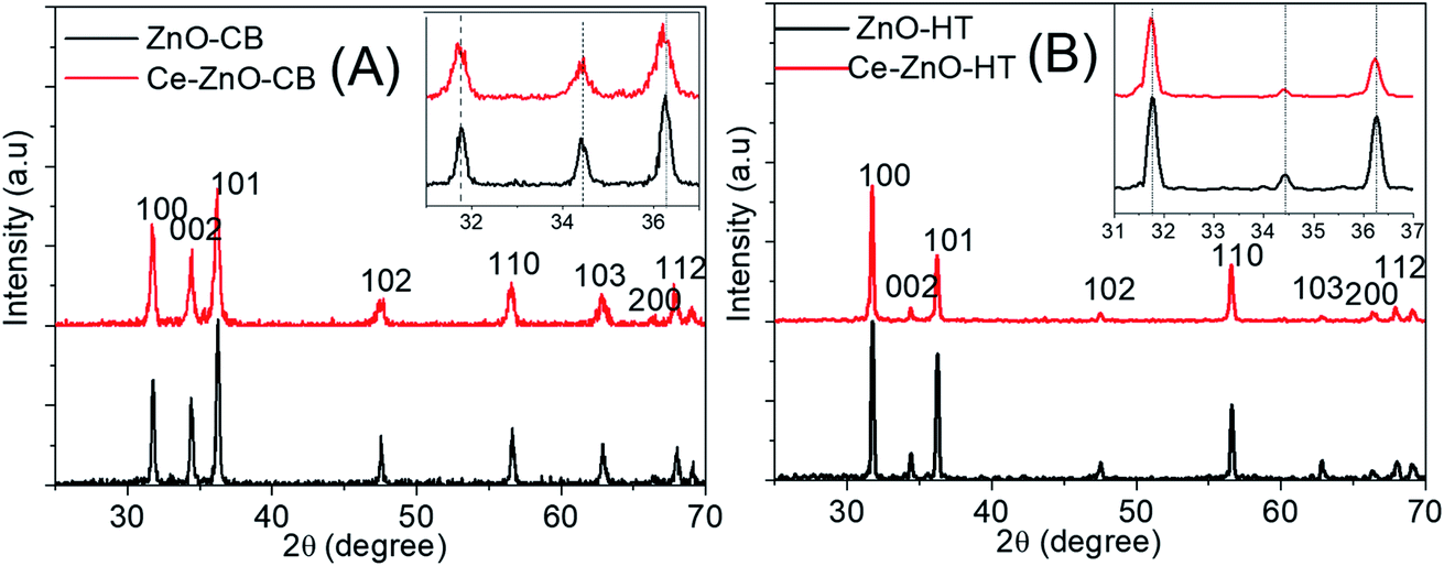 | ||
| Fig. 1 XRD diagrams of (A): Ce-ZnO-CB and ZnO-CB; (B): Ce-ZnO-HT and ZnO-HT. ZnO-CB represented pure ZnO NPs which were prepared by the combustion method. ZnO-HT represented pure ZnO NPs which were prepared by the combustion method. | ||
Fig. 1A and B were shown that both Ce-ZnO-HT and Ce-ZnO-CB appeared diffraction peaks of high intensity and sharpness corresponded to the planes (100), (002), (101), (102), (110), (103), (200) and (112) of ZnO wurtzite hexagonal structure.15,20 In addition, there were no diffraction peaks of Ce or cerium oxide phases. The remarkable thing was that diffraction peaks of Ce-ZnO-HT and Ce-ZnO-CB (i.e., (100), (002), (101)) were slightly drifted to a smaller 2θ angle than that of prepared ZnO NPs. The strength of the diffraction peaks is also reduced, indicating that Ce3+ ions are present in the ZnO lattice.41 Furthermore, the Ce doping reduced the crystal size compared to the synthetic ZnO NPs, and the lattice constant of the ZnO crystal was changed. However, the ratio of c/a was nearly unchanged – approximately 1.6 (Table 1). Predictably, cerium has entered the lattice of ZnO without changing its wurtzite structure. Similar observations were also reported in some literature.27,42,43 The slight change may cause by the ionic radii differences between Zn (0.74 Å) and Ce (1.03 Å).
| Material | D (nm) | a (Å) | b (Å) | c (Å) | c/a |
|---|---|---|---|---|---|
| Ce-ZnO-CB | 22 | 3.2513 | 3.2513 | 5.2255 | 1.607 |
| ZnO-CB | 34 | 3.2490 | 3.2490 | 5.2109 | 1.604 |
| Ce-ZnO-HT | 35 | 3.2539 | 3.2539 | 5.2087 | 1.601 |
| ZnO-HT | 39 | 3.2550 | 3.2550 | 5.2091 | 1.600 |
3.2 FT-IR spectra
FT-IR spectra of Ce-ZnO-HT, Ce-ZnO-CB are shown in Fig. 2. The O–H bond vibration of absorbed water on the surface was observed at broadband around 3450 cm−1.44 Besides, the corresponding bending vibration of H–O–H occurs close to 1610 cm−1.45 It was noticeable that the absorption peaks in the 440–570 cm−1 range were characterized by oxygen–metal bonding oscillation.20,46 The peak at 430 cm−1 was characterized for the Zn–O bond vibration and two sharp peaks at 450 cm−1 and 540 cm−1 of the Zn–O–Ce bending vibration of Ce-ZnO-CB and Ce-ZnO-HT, respectively. | ||
| Fig. 2 FT-IR spectra of Ce-ZnO-HT, Ce-ZnO-CB, and pure ZnO. | ||
3.3 SEM and TEM images
SEM and TEM images of prepared materials are shown in Fig. 3.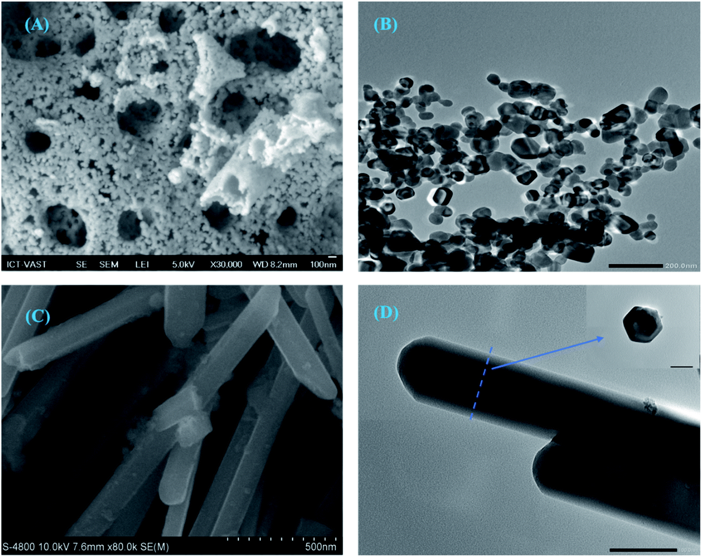 | ||
| Fig. 3 SEM image of Ce-ZnO-CB (A), TEM image of Ce-ZnO-CB (B), SEM image of Ce-ZnO-HT (C), and TEM image of Ce-ZnO-HT (D). | ||
SEM image of Ce-ZnO-CB showed that the material surface was evenly distributed and had high cavities. The supporting TEM image shows that Ce-ZnO-CB was 0D spherical nanoparticles with a fairly uniform diameter of about 20–30 nm (Fig. 3B). However, small particles readily agglomerate at ambient conditions. Unlike Ce-ZnO-CB, Ce-ZnO-HT was long, 1D rod-shaped, relatively uniform, and 80–120 nm in width and 30–60 nm in height. The TEM images of Ce-ZnO-HT was hexagonal structure. The surface of the material was porous and even. These results of particle size and shape are consistent with the above XRD results.
In the combustion method, the use of precursors greatly influences the morphology of the materials, such as size, porosity. The primary function of PVA in this study was to provide a polymeric network that inhibits cation mobility, thereby maintaining local stoichiometry and minimizing precipitation.47 Detailly, the presence of PVA in the aqueous solution provides hydroxyl groups (–OH) that can act as donating ligands (chelating) and the long chain of hydrocarbon. Thus, the metal cations can be surrounded in the form of M-(OH)n complexes between carbon chains. PVA wraps and covers the metal ions, preventing them from aggregation. As a result, the metal ions do not develop in size and do not precipitate, resulting in the creation of a cocoon-like structure in the polymeric structure of PVA.48 PVA was later acted as an organic fuel in the combustion process. Self-combustion occurs as a result of the chemical energy generated by the exothermic process. Nanoparticles with a spherical shape, high purity, and homogeneity are created.49
On the other hand, the formation of rod shape Ce-ZnO by the hydrothermal method began with nucleation from the precursor solution once the solution achieved supersaturation.50 When the concentrations of Zn2+ and −OH in the solution approach saturation, tiny ZnO nuclei form spontaneously in the solution follows eqn (3) and (4). Then, the anisotropic nanoparticles of ZnO join together and rearrange, pushed by interfacial free energy and the inability of water solution.
| Zn(OH)42−→ Zn2+ + 4 [−OH] | (3) |
| Zn2+ + 2 [−OH]→ ZnO + H2O | (4) |
The favored growth plane obeys the rule that the whole system maintains with the lowest energy requirement. Since the (0 0 1) faces have higher symmetry levels (C6v) than other faces, the growth along the c-axis ((0 0 1) direction) is more favorable.51 According to Hu et al. (2002), the growth rate along the (0 0 1) direction was twice as fast as for other directions.52,53 Thus, in typical hydrothermal conditions, a well-grown ZnO nanorod with an aspect ratio of >3 is shown in Fig. 3C. This study result of 1 D rod shape Ce-ZnO particles is well agreed with the discussion above.
3.4 BET results
Porosities of Ce-ZnO-HT and Ce-ZnO-CB were studied by nitrogen adsorption isotherm at low temperatures. The specific surface area was determined by the method of Brunauer–Emmett–Teller (BET). The nitrogen adsorption–desorption isotherms of these materials are shown in Fig. 4. This figure showed that both materials exhibited structures between types II and IV isothermal types, which were characterized by large and medium capillary structures. In addition, the hysteresis loop H3 was observed in the relative pressure range (P/P0) in the range of 0.85–1.0 of the Ce-ZnO-CB. It showed that these materials had slit-shaped voids due to the aggregation of particles and the formation of holes and cavities in the material. Within this pressure range, an H4-type hysteresis loop was observed for Ce-ZnO-HT, which was related to the aggregation of particles formed hexagonal rod-like material. This result was similar to the analysis result from the SEM image obtained above. In addition, the hysteresis loop H3 and H4 did not show any limited adsorption at the high P/P0 range. The values of these two materials' specific surface area, volume, and pore size were calculated by the BET method and given in Table 2. This result showed that the specific surface charge, volume, and size of pores of Ce-ZnO-HT were larger than those of Ce-ZnO-CB.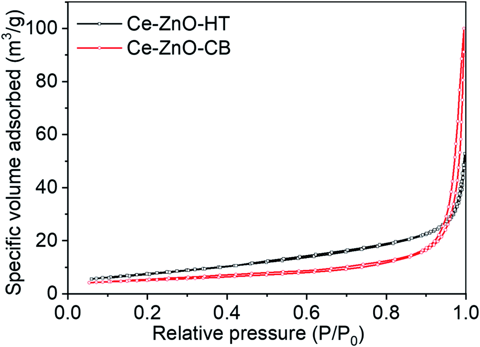 | ||
| Fig. 4 Adsorption and desorption isotherm of Ce-ZnO-CB and Ce-ZnO-HT NPs. | ||
| Material | Specific surface area (m2 g−1) | Pore volume (cm3 g−1) | Pore size (Å) |
|---|---|---|---|
| Ce-ZnO-CB | 17.6 | 0.15 | 354 |
| Ce-ZnO-HT | 21.5 | 0.32 | 534 |
It's worth noting that the hydroxyl group is a weak electron-donating group, resulting in poor chelating and aggregation of metal ions.54 Thus, the prepared Ce-ZnO-CB readily agglomerated after the organic removal step, as shown in Fig. 3A and B. As a result, the pore size of Ce-ZnO-CB becomes smaller than those of Ce-ZnO-HT. One possible solution for avoiding the agglomeration of nanoparticles is the use of additional chelating reagents other than PVA only. For example, it was reported that the use of citric acid (CA), ethylenediaminetetraacetic acid (EDTA), or cetrimonium bromide (CTAB) might reduce significantly the aggregating of cations. The addition of other chelating agents provides additional functional groups capable of interacting with metal cations that are not easily chelated by main chelating agents.
3.5 DRS and PL results
Diffuse reflection spectra (DRS) of Ce-ZnO-HT, Ce-ZnO-CB, and pure ZnO NPs were shown in Fig. 5A, and Tauc's plots are drawn as the variation of (αhν)1/2(eV cm−1)1/2 vs. Eg (eV) (Fig. 5B). Fig. 5A demonstrated that all prepared materials absorb effectively in the UV-Vis range (<3.20 eV).25 The absorption ability was typically reduced when the irradiation came close to the visible area, particularly for pristine ZnO. When Ce was dopped into ZnO, the visible light absorption capacity of Ce-ZnO-HT was significantly increased, as shown in Fig. 5A. This was confirmed when a change in the optical absorption margin of Ce-doped ZnO NPs to visible light was detected, and the Ce-doped ZnO material's bandgap was lower than that of pure ZnO (Fig. 5B). Specifically, the bandgap of Ce-ZnO-HT and Ce-ZnO-CB were both 2.95 eV, while that of pure ZnO was 3.06 eV. The narrowed bandgap in Ce-ZnO NPs could be explained by the interaction of cerium's 5d, 4f orbitals with the conduction band of ZnO to create a new bandgap energy state.18,55,56 This new energy state had the ability to absorb visible light. In addition, the doping of Ce into ZnO increased lattice defects which are highly related to the formation of electron trap centers.41,57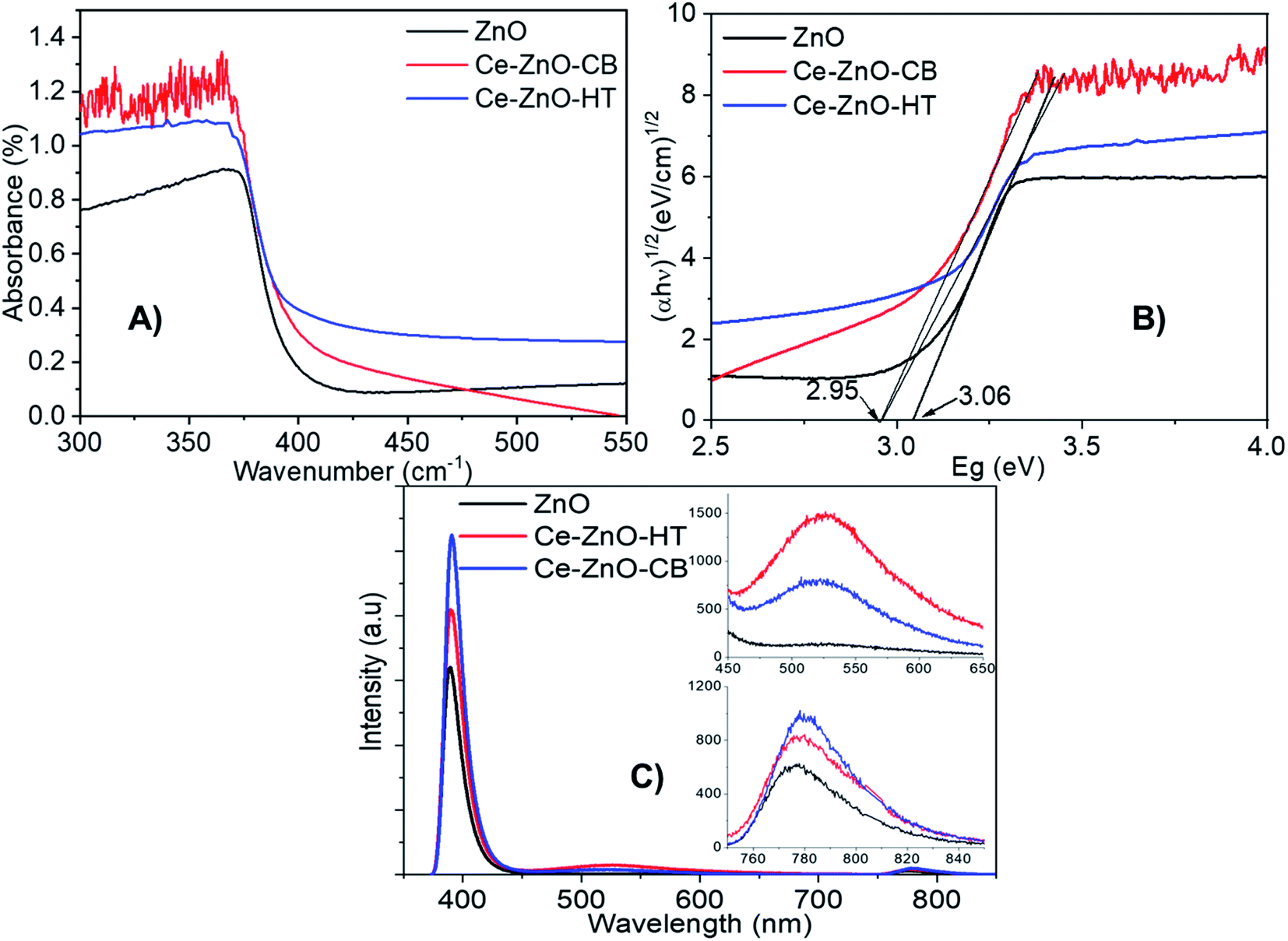 | ||
| Fig. 5 (A), (B) DRS spectra; (C) PL spectra of Ce-ZnO-HT, Ce-ZnO-CB and pure ZnO. | ||
The PL spectrum (Fig. 5C) was further demonstrated when the emission peaks of Ce-ZnO-HT and Ce-ZnO-CB in the wavelength range 450–600 nm (i.e., visible range) with the peaks at 522 nm were observed. This green-blue emission was caused by the presence of an oxygen vacancy,42,56 whereas this peak did not emerge in pure ZnO NPs. In this wavelength range, the emissive peak intensity of Ce-ZnO-HT is twice as high as that of Ce-ZnO-CB. Accordingly, the concentration of oxygen vacancies in the Ce-ZnO-HT was significantly higher than that in the Ce-ZnO-CB.
Furthermore, the appearance of near-infrared (NIR) emission peaks, i.e., wavelengths in the range of 750–850 nm (Fig. 5C), are observed. The NIR emission band in ZnO is believed to be caused by a shift from the donor to acceptor center (DA mechanism), which is analogous to self-activated emission.58 These emission peaks are related to the presence of oxygen-hole defects inherent in ZnO, and Ce doping may increase the concentration of these defects. Thus, a substantial increase in oxygen-hole defect produced by modest doping of Ce content was demonstrated on the PL spectrum by emission peaks in both the visible light and NIR bands. Because of the increase in surface defects, Ce doping was shown to improve the photocatalytic effectiveness of ZnO as a photocatalyst under visible light.41,59,60
As clearly seen from Fig. 5C, all materials show peaks in the range 390–391 nm (i.e., ultraviolet range). These peaks are assigned to the characteristic peaks of ZnO, which are resulted from the direct electron–hole recombination process from the near band-edge transition. Firstly, we note a decrease in PL intensity, indicating that Ce doped ZnO has a low electron–hole recombination rate.61,62 Thus, ZnO may exhibit better photocatalytic activity than Ce-ZnO under UV irradiation. Overall, data shows that introducing cerium into the structure of zinc oxide decreases ZnO's photocatalytic effectiveness under UV light, instead significantly increasing the photocatalytic efficiency under visible light.
3.6 XPS results
The surface composition and chemical state of Ce-ZnO-HT and Ce-ZnO-CB materials was studied by the XPS method, which is demonstrated in Fig. 6. The figure showed the binding energy peaks of Zn2p, O 1s, and Ce 3d. Fig. 6a and b were shown that binding peaks at 1021 eV, 1044 eV, and 530 eV were identified as Zn 2p3/2, Zn 2p1/2, and O 1s, respectively. These peaks characterize for Zn–O bond in the ZnO network.24 As can be seen in Fig. 6c, there were two spin-orbital clusters of Ce 3d3/2 and Ce 3d5/2. For the orbitals of Ce3d5/2, the cluster of peaks v0, v, v′′, u, u0 corresponded to the binding energy levels 880.9 eV, 882.7 eV, 885.3 eV, 901.3 eV, and 899.1 eV. The remaining peaks u′, u′′, and u′′′ exhibited binding energy levels of 903.4 eV, 907.3 eV, and 916.7 eV, respectively, and were characterized by Ce3d3/2 orbitals.36,43 However, with Ce-ZnO-CB, these peaks had a slight shift towards the higher binding energy. The two spin-orbital pairs identified as Ce4+ had the highest binding energy (i.e., u′, v′), while the two spin-orbital pairs identified as Ce3+ had the lowest binding energy (i.e., u0, v0). This demonstrated that cerium existed in the material in two oxidation states, Ce3+, Ce4+, and mainly Ce4+. | ||
| Fig. 6 High-resolution XPS spectra of (A) Zn2p3/2, (B) O 1s, and (C) Ce 3d of Ce-ZnO-HT and Ce-ZnO-CB. | ||
3.7 Photocatalytic activity
A preliminary experiment was performed to determine the linear range of the MB solution regards to optical absorptivity. The results in Fig. 7A show that the concentration range from 1–15 ppm gives the best linear optical density, corresponding to the regression coefficient R2 = 0.995. Besides, the UV-VIS spectroscopy results of MB solutions showed that the maximum absorption wavelength of MB was 664 nm.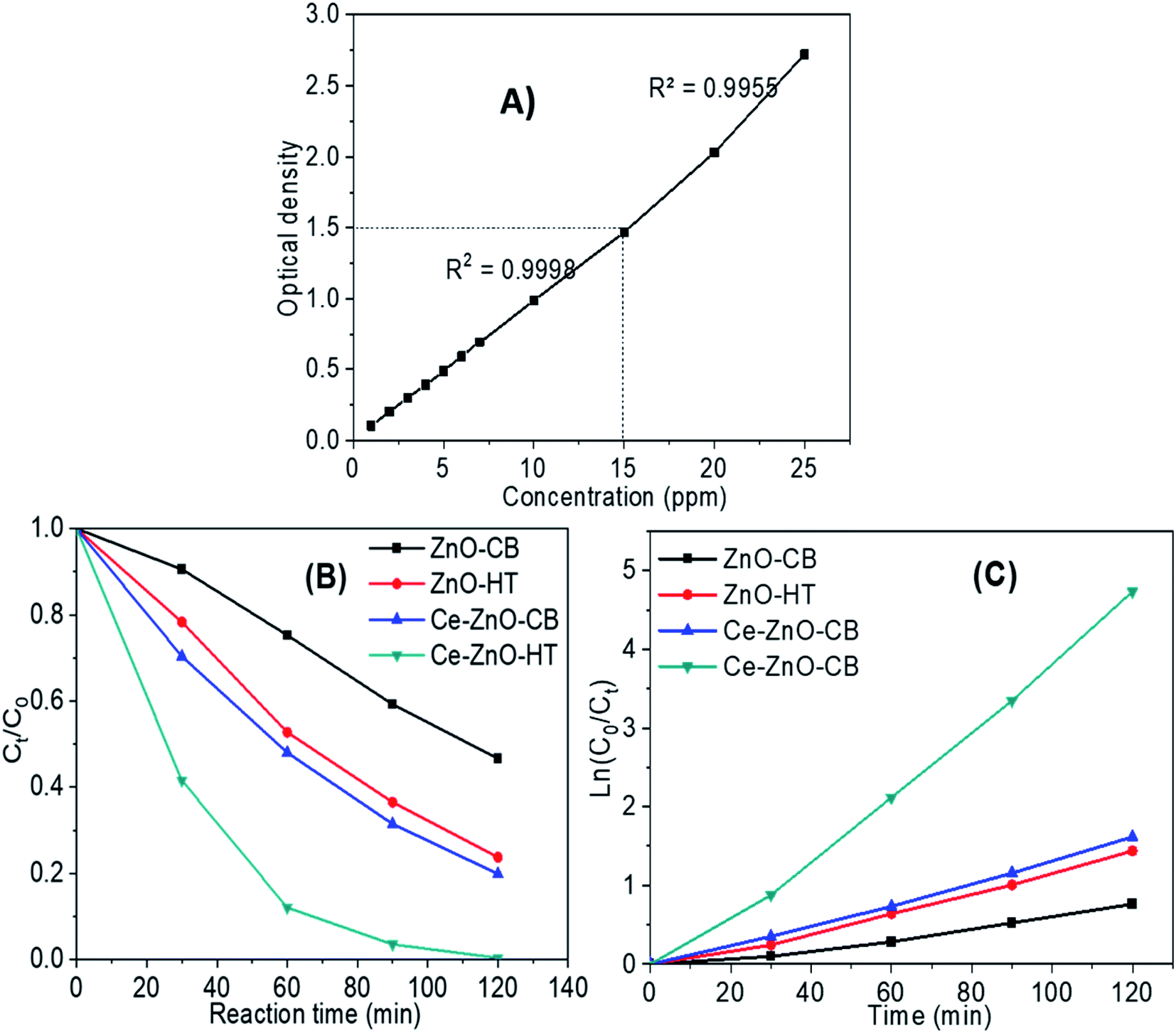 | ||
| Fig. 7 (A) Relationship between the MB solution and optical absorptivity (B) MB decomposition of materials under visible light; (C) correlation of ln(C0/Ct) and reaction time. | ||
Fig. 7B depicts MB decomposition during visible light irradiation. The results validate the predictions from the PL spectrum in Section 3.5. Briefly, the photodegradation efficiency using doped ZnO (i.e., Ce-ZnO) was much higher than pure ZnO. Besides, the result also agrees that Ce-ZnO-HT exhibits a higher photocatalyst capacity than Ce-ZnO-CB. After 90 minutes, the MB concentration decreased over 96% by Ce-ZnO-HT, whereas that of Ce-ZnO-CB was around 70%.
The MB decomposition kinetics using Ce-ZnO photocatalysts are shown in Fig. 7C and Table 3. The graph demonstrated strong linearity between ln(C0/Ct) and time for all materials, with a regression coefficient R2 close to 1 (Table 3). It is shown that the first-order kinetics model was well described the MB decomposition process under visible light.
| Material | The first-order kinetic equation | Regression coefficient R2 |
|---|---|---|
| ZnO-CB | y = 0.0062x − 0.0289 | 0.9934 |
| ZnO-HT | y = 0.0121x − 0.062 | 0.9922 |
| Ce-ZnO-CB | y = 0.0135x − 0.0359 | 0.9971 |
| Ce-ZnO-HT | y = 0.0398x − 0.1723 | 0.9944 |
3.8 Recyclability
After usage, the Ce-ZnO-HT and Ce-ZnO-CB catalysts were centrifuged, washed three times with distilled water, and dried at 80 °C for ten hours. Fig. 8 depicts the findings of MB degradation from the second time after recovery.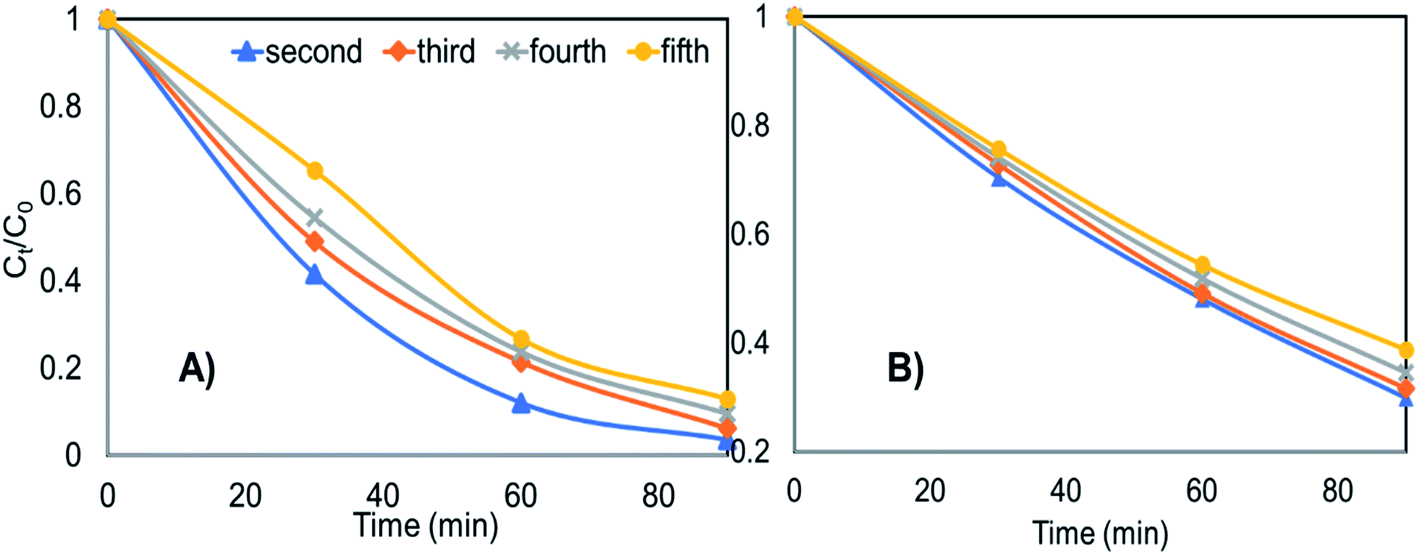 | ||
| Fig. 8 The recyclability of materials in degrading MB after several recycle (A) Ce-ZnO-HT (B) Ce-ZnO-CB. | ||
Fig. 8 clearly shows that both materials are capable of being reused multiple times. After five times of reuse, Ce-ZnO-HT only decreased MB degradability by 9.5%, while Ce-ZnO-CB material only reduced MB degradability by 9.0%. The degradation efficiency of the material slightly diminishes over time; however, the Ce-ZnO-HT material always has greater photocatalytic efficiency than the Ce-ZnO-CB materials. The cause might be from the strong aggregation of small particles in the aqueous solution. This aggregation decreases the surface area of the material, resulting in a reduction in the material's photocatalytic capacity. However, the results reveal that the two materials (i.e., Ce-ZnO-CB and Ce-ZnO-HT) are still quite recyclable.
3.9 Photocatalysis mechanism
On the surface of materials, a photo-induced electron and a hole formed when ZnO received a photon (eqn (5)). Cerium presence inside the ZnO network, which was presented mainly as Ce4+ acted as an electron trap (eqn (6)). These electron traps captured photo-illuminate electrons. Thereby, they reduced the rate of recombination of photo-illuminate electrons and holes and increased the number of ˙O2− (eqn (6) and (7)), and may enhance the photochemical activity of materials.63,64 Then, the ˙O2− radical anions subsequently convert to hydroxyl radicals (eqn (8)).65| ZnO + hν → ZnO + h+ + e− | (5) |
| e− + Ce4+ → Ce3+ | (6) |
| O2 + Ce3+ → Ce4+ + ˙O2− | (7) |
| ˙O2− + H2O → ˙OH + −OH | (8) |
In the field of nanocatalyst, morphology has been considered an essential factor for photocatalytic activity. In a study by Mclaren et al., the authors found that the ZnO particle size did not significantly affect the photocatalytic reaction rate, but the morphology factor played an important role.66 The photocatalytic reaction rate of hexagonal disc nanocrystals had at least five times higher than that of rod-shaped crystals. This was because polar surfaces of (001) and (00![[1 with combining macron]](https://www.rsc.org/images/entities/char_0031_0304.gif) ) were more active than nonpolar surfaces that were perpendicular to them and had good adsorption capacity of H2O and −OH. Subsequently, it was beneficial for creating ˙OH radicals (eqn (9) and (10)).66,67
) were more active than nonpolar surfaces that were perpendicular to them and had good adsorption capacity of H2O and −OH. Subsequently, it was beneficial for creating ˙OH radicals (eqn (9) and (10)).66,67
| h+ + H2O → ˙OH + H+ | (9) |
| h+ + −OH → ˙OH | (10) |
Overall, in the solution, there are many strong reactive oxidants such as ˙OH, ˙O2−, h+, e−. Fig. 9 shows the findings of the strapping experiments, which provide a clearer understanding of the importance of oxidants. As can be seen, when scavengers are present, the effectiveness of MB degradation decreases. This meant that all of the oxidants studied in this study contributed to the decomposition of MB in some way. However, the reduction rate was varied largely with different reagents. More specifically, the decomposition efficiency was slightly reduced when AgNO3 or 1,4-benzoquinone were added. Adding EDTA or isopropanol, on the other hand, resulted in a significant decrease in MB degradation efficiency, demonstrating that holes and hydroxyl radicals are the main contributors to MB degradation. When compared to e−, ˙O2− radicals contributed more to the MB decomposition process. Generalize, the roles of the oxidants can be arranged in the order:
| h+ ≈ ˙OH > ˙O2− > e−. |
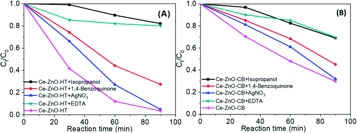 | ||
| Fig. 9 MB degradation during 90 min when present radical scavengers (A) by Ce-ZnO-HT (B) by Ce-ZnO-CB. | ||
There is a noticeable difference when the two catalysts (i.e., Ce-ZnO-HT and Ce-ZnO-CB) are examined closely. The ˙OH and ˙O2− radical ions are more prominent in Ce-ZnO-HT than in Ce-ZnO-CB. The hydroxyl radical in Ce-ZnO-HT is dominant over Ce-ZnO-CB, which may be related to the morphological characteristics and surface activity as discussed above. Generally, hydrothermal synthesis occurs in a solution with high autogenous pressure, takes place for a long time, leading to a higher concentration of Ce3+ than in the case of combustion synthesis, where the reaction is very fast. As a result, the Ce3+/Ce4+ ratio in Ce-ZnO-HT was higher than in Ce-ZnO-CB. According to eqn (6), (7) and (8), the higher Ce3+/Ce4+ ratio leads to the superiority formation of ˙OH and ˙O2− radical ions.
To sum up, the proposed mechanism of the photocatalytic process using Ce-ZnO catalysts is schematically explained in Fig. 10.
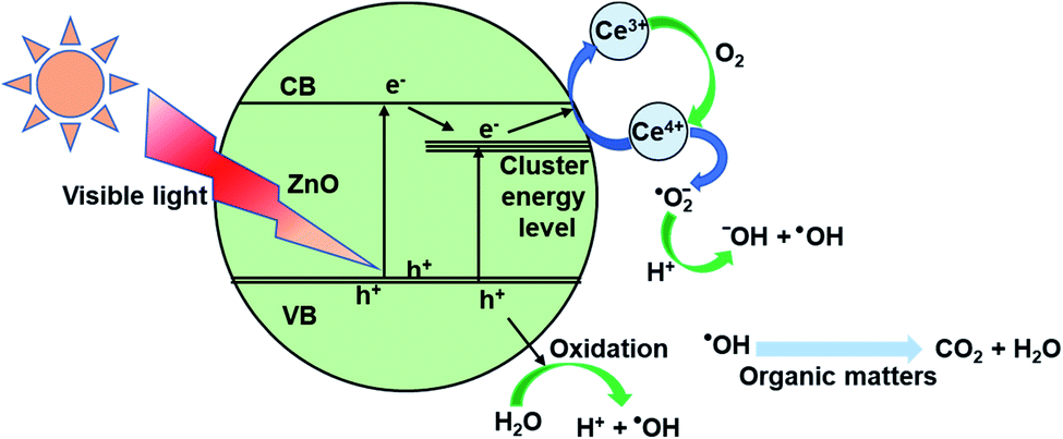 | ||
| Fig. 10 Schematic illustration photocatalytic mechanism for Ce-ZnO nanocatalysts. | ||
4. Conclusion
Ce-ZnO materials were successfully synthesized by solvothermal and combustion methods. Both Ce-ZnO-HT and Ce-ZnO-CB materials had a single-phase hexagonal wurtzite structure with high crystallization. Bandgap energy of Ce-ZnO-HT and Ce-ZnO-CB materials was approximate 2.95 eV and smaller than that of ZnO. MB decomposition efficiency under visible light of Ce-ZnO-HT, Ce-ZnO-CB materials was higher than that of ZnO synthesized under the same conditions. Especially, the photocatalytic activity of Ce-ZnO-HT was higher than that of Ce-ZnO-CB material. The difference in photocatalytic activity was caused by the synthetic method, which creates differences in surface morphology, specific surface area, and oxygen vacancy concentration. Ce-ZnO-HT were 1D rodded shape while Ce-ZnO-CB were sphere shape. Specific surface area and oxygen vacancies of Ce-ZnO-HT were higher than Ce-ZnO-CB. Photo-induced electrons, i.e., e− and ˙O2− were shown to be less major contributors to MB degradation than ˙OH and h+ in the photodegradation process investigation.Author contribution
Thi Viet Ha Luu: conceptualization, methodology, writing - original draft, project administration. Quang Bac Nguyen: formal analysis, validation, writing - review & editing. Ngoc Nhiem Dao: data curation, resources. Minh Dai Luu: supervision. Van Dat Doan: investigation, resources. Ngoc Chuc Pham: data curation, software. Thi Lim Duong: investigation, resources, visualization. Ngo Nghia Pham: writing - review & editing.Conflicts of interest
The authors declare that they have no known competing interests that could have appeared to influence the work reported in this paper.Acknowledgements
Nguyen Quang Bac was funded by Vingroup JSC and supported by the Master, PhD Scholarship Programme of Vingroup Innovation Foundation (VINIF), Institute of Big Data, code VINIF.2021.TS.101.References
- Ü. Özgür, Y. I. Alivov, C. Liu, A. Teke, M. A. Reshchikov, S. Doǧan, V. Avrutin, S. J. Cho and H. Morko, J. Appl. Phys., 2005, 98, 1–103 CrossRef.
- C. B. Ong, L. Y. Ng and A. W. Mohammad, Renew. Sustain. Energy Rev., 2018, 81, 536–551 CrossRef CAS.
- V. N. Kalpana, B. A. S. Kataru, N. Sravani, T. Vigneshwari, A. Panneerselvam and V. Devi Rajeswari, OpenNano, 2018, 3, 48–55 CrossRef.
- A. Kolodziejczak-Radzimska and T. Jesionowski, Materials (Basel)., 2014, 7, 2833–2881 CrossRef CAS PubMed.
- J. Jiang, J. Pi and J. Cai, Bioinorg. Chem. Appl., 2018, 2018, 18 Search PubMed.
- S. Sharma, K. Kumar, N. Thakur, S. Chauhan and M. S. Chauhan, Bull. Mater. Sci., 2020, 43, 1–10 CrossRef.
- Y. Li, G. W. Meng, L. D. Zhang and F. Phillipp, Appl. Phys. Lett., 2000, 76, 2011–2013 CrossRef CAS.
- M. L. Zhang, F. Jin, M. L. Zheng, J. Liu, Z. S. Zhao and X. M. Duan, RSC Adv, 2014, 4, 10462–10466 RSC.
- L. Zhu and W. Zeng, Sensors Actuators, A Phys., 2017, 267, 242–261 CrossRef CAS.
- I. Rosso, C. Galletti, M. Bizzi, G. Saracco and V. Specchia, Ind. Eng. Chem. Res., 2003, 42, 1688–1697 CrossRef CAS.
- K. H. Le, M. D. B. Nguyen, L. D. Tran, H. P. Nguyen Thi, C. Van Tran, K. Van Tran, H. P. Nguyen Thi, N. Dinh Thi, Y. S. Yoon, D. D. Nguyen and D. D. La, Prog. Org. Coatings, 2021, 158, 106339 CrossRef CAS.
- C. Berguerand, A. Yarulin, F. Cárdenas-Lizana, J. Wärnå, E. Sulman, D. Y. Murzin and L. Kiwi-Minsker, Ind. Eng. Chem. Res., 2015, 54, 8659–8669 CrossRef CAS.
- S. Liang, K. Xiao, Y. Mo and X. Huang, J. Memb. Sci., 2012, 394–395, 184–192 CrossRef CAS.
- C. Lizama, J. Freer, J. Baeza and H. D. Mansilla, Catal. Today, 2002, 76, 235–246 CrossRef CAS.
- T. Vu Anh, T. A. T. Pham, V. H. Mac and T. H. Nguyen, J. Anal. Methods Chem., 2021, 2021, 24–26 Search PubMed.
- J. Yu and X. Yu, Environ. Sci. Technol., 2008, 42, 4902–4907 CrossRef CAS PubMed.
- R. Hong, T. Pan, J. Qian and H. Li, Chem. Eng. J., 2006, 119, 71–81 CrossRef CAS.
- J. Iqbal, X. Liu, H. Zhu, Z. B. Wu, Y. Zhang, D. Yu and R. Yu, Acta Mater., 2009, 57, 4790–4796 CrossRef CAS.
- C. Karunakaran, P. Gomathisankar and G. Manikandan, Mater. Chem. Phys., 2010, 123, 585–594 CrossRef CAS.
- M. Faisal, A. A. Ismail, A. A. Ibrahim, H. Bouzid and S. A. Al-Sayari, Chem. Eng. J., 2013, 229, 225–233 CrossRef CAS.
- N. Vinothkumar and M. De, Mater. Renew. Sustain. Energy, 2014, 3, 25 CrossRef.
- A. S. Weber, A. M. Grady and R. T. Koodali, Catal. Sci. Technol., 2012, 2, 683–693 RSC.
- S. M. Hosseini, I. A. Sarsari, P. Kameli and H. Salamati, J. Alloys Compd., 2015, 640, 408–415 CrossRef CAS.
- Y. M. Hao, S. Y. Lou, S. M. Zhou, R. J. Yuan, G. Y. Zhu and N. Li, Nanoscale Res. Lett., 2012, 7, 100 CrossRef PubMed.
- L. T. V. Ha, L. M. Dai, D. T. Lim, D. N. Nhiem and N. N. Pham, J. Chinese Chem. Soc., 2020, 67, 1631–1643 CrossRef CAS.
- L. Wang, Z. Ji, J. Lin and P. Li, Mater. Sci. Semicond. Process., 2017, 71, 401–408 CrossRef CAS.
- P. Pandey, R. Kurchania and F. Z. Haque, Opt. Spectrosc., 2015, 119, 666–671 CrossRef CAS.
- W. Bousslama, H. Elhouichet and M. Férid, Optik, 2017, 134, 88–98 CrossRef CAS.
- J. Zhao, L. Wang, X. Yan, Y. Yang, Y. Lei, J. Zhou, Y. Huang, Y. Gu and Y. Zhang, Mater. Res. Bull., 2011, 46, 1207–1210 CrossRef CAS.
- V. Kumari, A. Mittal, J. Jindal, S. Yadav and N. Kumar, Front. Mater. Sci., 2019, 13, 1–22 CrossRef.
- C. S. Chen, T. G. Liu, L. W. Lin, X. D. Xie, X. H. Chen, Q. C. Liu, B. Liang, W. W. Yu and C. Y. Qiu, J. Nanoparticle Res., 2013, 15, 1295 CrossRef CAS PubMed.
- C. N. Peter, W. W. Anku, R. Sharma, G. M. Joshi, S. K. Shukla and P. P. Govender, Ionics, 2019, 25, 327–339 CrossRef CAS.
- S. Xie, Y. Liu, Z. Chen, X. Chen and X. Wang, RSC Adv., 2013, 3, 26080–26085 RSC.
- R. Li, G. Dong and G. Chen, New J. Chem., 2015, 39, 6854–6863 RSC.
- H. L. H. B. H. L. Liu, L. H. Fei, H. L. H. B. H. L. Liu, J. H. Yang, X. Jin, M. Gao, Y. Liu, X. Cheng and X. Zhang, J. Mater. Sci. Mater. Electron., 2013, 24, 58–63 CrossRef CAS.
- X. P. Cao, D. Li, W. H. Jing, W. H. Xing and Y. Q. Fan, J. Mater. Chem., 2012, 22, 15309–15315 RSC.
- B. Hu, Q. Sun, C. Zuo, Y. Pei, S. Yang, H. Zheng and F. Liu, Beilstein J. Nanotechnol., 2019, 10, 1157–1165 CrossRef CAS PubMed.
- O. Yayapao, S. Thongtem, A. Phuruangrat and T. Thongtem, Ceram. Int., 2013, 39, S563–S568 CrossRef CAS.
- T. Liu, L. Wang, X. Lu, J. Fan, X. Cai, B. Gao, R. Miao, J. Wang and Y. Lv, RSC Adv, 2017, 7, 12292–12300 RSC.
- S. H. Chen, Y. S. Jiang and H. Y. Lin, ACS Omega, 2020, 5, 8927–8933 CrossRef CAS PubMed.
- H. Parangusan, D. Ponnamma and M. A. A. Al-Maadeed, Bull. Mater. Sci., 2019, 42, 179 CrossRef.
- D. K. Sharma, K. K. Sharma, V. Kumar and A. Sharma, J. Mater. Sci. Mater. Electron., 2016, 27, 10330–10335 CrossRef CAS.
- J. Iqbal, X. Liu, H. Zhu, C. Pan, Y. Zhang, D. Yu and R. Yu, J. Appl. Phys., 2009, 106, 1–7 CrossRef.
- P. Caregnato, K. R. Espinosa Jiménez and P. I. Villabrille, Catal. Today, 2021, 372, 183–190 CrossRef CAS.
- L. Kumaresan, A. Prabhu, M. Palanichamy, E. Arumugam and V. Murugesan, J. Hazard. Mater., 2011, 186, 1183–1192 CrossRef CAS PubMed.
- G. N. Dar, A. Umar, S. A. Zaidi, A. A. Ibrahim, M. Abaker, S. Baskoutas and M. S. Al-Assiri, Sensors Actuators, B Chem., 2012, 173, 72–78 CrossRef CAS.
- T. Liu, Y. Xu and J. Zhao, J. Am. Ceram. Soc., 2010, 93, 3637–3641 CrossRef CAS.
- Y.-K. Sun and O. In-Hwan, Ind. Eng. Chem. Res., 1996, 35, 4286–4300 CrossRef.
- S. Tabesh, F. Davar and M. R. Loghman-Estarki, Ceram. Int., 2017, 43, 10247–10252 CrossRef CAS.
- H. Wei, Y. Wu, N. Lun and C. Hu, Mater. Sci. Eng. A, 2005, 393, 80–82 CrossRef.
- L. Guo, Y. L. Ji, H. Xu, P. Simon and Z. Wu, J. Am. Chem. Soc., 2002, 124, 14864–14865 CrossRef CAS PubMed.
- J. Q. Hu, Q. Li, N. B. Wong, C. S. Lee and S. T. Lee, Chem. Mater., 2002, 14, 1216–1219 CrossRef CAS.
- L. Wang, L. X. Chang, L. Q. Wei, S. Z. Xu, M. H. Zeng and S. L. Pan, J. Mater. Chem., 2011, 21, 15732–15740 RSC.
- N. Yahya, F. Aziz, A. Jamaludin, A. Aizat, M. A. Mutalib, J. Jaafar, W. J. Lau, N. Yusof, W. N. W. Salleh and A. F. Ismail, Ind. Eng. Chem. Res., 2019, 58, 609–617 CrossRef CAS.
- S. Chakma and V. S. Moholkar, Ultrason. Sonochem., 2015, 22, 287–299 CrossRef CAS PubMed.
- N. Kannadasan, N. Shanmugam, S. Cholan, K. Sathishkumar, G. Viruthagiri and R. Poonguzhali, Mater. Charact., 2014, 97, 37–46 CrossRef CAS.
- D. Scott Bohle and C. J. Spina, J. Am. Chem. Soc., 2009, 131, 4397–4404 CrossRef PubMed.
- M. Koyano, P. QuocBao, L. T. ThanhBinh, L. HongHa, N. NgocLong and S. Katayama, Phys. Status Solidi Appl. Res., 2002, 193, 125–131 CrossRef CAS.
- Y.-I. Jung, B.-Y. Noh, Y.-S. Lee, S.-H. Baek, J. H. Kim and I.-K. Park, Nanoscale Res. Lett., 2012, 7, 43 CrossRef PubMed.
- Q. Luo, L. S. Wang, H. Z. Guo, K. Q. Lin, Y. Chen, G. H. Yue and D. L. Peng, Appl. Phys. A Mater. Sci. Process., 2012, 108, 239–245 CrossRef CAS.
- S. Ben Ameur, H. BelHadjltaief, B. Duponchel, G. Leroy, M. Amlouk, H. Guermazi and S. Guermazi, Heliyon, 2019, 5, e01912 CrossRef CAS PubMed.
- M. Dhanalakshmi, K. Saravanakumar, S. L. Prabavathi and V. Muthuraj, Inorg. Chem. Commun., 2020, 111, 107601 CrossRef CAS.
- M. Samadi, M. Zirak, A. Naseri, E. Khorashadizade and A. Z. Moshfegh, Thin Solid Films, 2016, 605, 2–19 CrossRef CAS.
- K. M. Lee, C. W. Lai, K. S. Ngai and J. C. Juan, Water Res., 2016, 88, 428–448 CrossRef CAS PubMed.
- F.-H. Chu, C.-W. Huang, C.-L. Hsin, C.-W. Wang, S.-Y. Yu, P.-H. Yeh and W.-W. Wu, Nanoscale, 2012, 4, 1471–1475 RSC.
- A. Mclaren, T. Valdes-Solis, G. Li and S. C. Tsang, J. Am. Chem. Soc., 2009, 131, 12540–12541 CrossRef CAS PubMed.
- N. M. Flores, U. Pal, R. Galeazzi and A. Sandoval, RSC Adv., 2014, 4, 41099–41110 RSC.
| This journal is © The Royal Society of Chemistry 2021 |