
 Open Access Article
 This Open Access Article is licensed under a Creative Commons Attribution-Non Commercial 3.0 Unported Licence
Symmetric and asymmetric overgrowth of a Ag shell onto gold nanorods assisted by Pt pre-deposition†
Qi Zhang,
Tian-Song Deng *,
Ming-Zhang Wei,
Xi Chen,
Zhiqun Cheng,
Shiqi Li and
Yi-Jie Gu
*,
Ming-Zhang Wei,
Xi Chen,
Zhiqun Cheng,
Shiqi Li and
Yi-Jie Gu
School of Electronics and Information Engineering, Hangzhou Dianzi University, Hangzhou 310018, P. R. China. E-mail: dengts@pku.edu.cn
First published on 25th October 2021
Abstract
The plasmonic properties of noble metallic nanoparticles could be tuned by morphology and composition, enabling opportunities for applications in sensors, photocatalysis, biomedicine, and energy conversion. Here, we report a method of the symmetric and asymmetric overgrowth of a Ag shell onto gold nanorods assisted by Pt pre-deposition via a 2-step approach. Firstly, gold nanorods (AuNRs), synthesized via a seed-mediated method, were used as seeds to form a AuNR–Pt structure, by using K2PtCl4 as the precursor. In this step, most of the Pt material was selectively deposited on the tips of the AuNR. Secondly, by using AgNO3 as the precursor, a Ag shell was overgrown on the surface of the AuNRs–Pt nanoparticles, resulting in a (AuNR–Pt)–Ag core–shell tri-metallic nanostructure. Due to the surface energy and lattice matching between Au and Ag, the Ag shell preferred to be epitaxially overgrown on the side of AuNR. The Ag shell thickness and symmetry of the (AuNR–Pt)–Ag could be tuned by changing the amounts of AgNO3 precursor. With the increase of the Ag shell thickness, the (AuNR–Pt)–Ag nanostructures changed from symmetric to asymmetric. The obtained (AuNR–Pt)–Ag nanostructures were studied using UV-vis-NIR spectroscopy, transmission electron microscopy, EDS mapping, DLS, and ICP-MS. The growth mechanism was discussed.
1. Introduction
Owing to the development of wet chemistry synthetic techniques, gold nanoparticles with various shapes have been successfully synthesized, such as spheres,1 plates and rings,2 cups,3 and rods.4 Among these gold nanoparticles, gold nanorods (AuNRs) have been extensively studied,5–7 due to their special plasmonic properties, that is, longitudinal localized surface plasmon resonance (LSPR) along their long-axis, and transverse LSPR along their short-axis. The longitudinal LSPR of AuNRs can be simply tuned by the aspect ratio (length/diameter) of the AuNR, from the visible (∼600 nm) to the near infrared region (>1200 nm). Thus, AuNRs have shown great promise in optical devices,8 biological sensing,9 photochemistry,10 photonics,11 catalysis,12,13 and surface-enhanced Raman spectroscopy (SERS).14,15 In recent years, overgrowth of a second metal on AuNRs, such as Pt, Pd, and Ag (named AuNR–M afterwards, M = Pt, Pd, or Ag), have been extensively studied. Usually, the AuNR–M bimetallic nanostructure has the excellent properties of the two metals. For instance, the AuNR–Pt nanostructure improves the catalytic performance,16,17 while the AuNR–Ag has stronger surface plasmon resonance,18 and can be used as a probe to treat disease.19–21 Moreover, compared with symmetrical AuNR–M core–shell nanostructures, asymmetric nanostructures have unique plasmonic properties due to their special morphology. Particularly, the AuNR–Ag core–shell nanostructure changed the position of the LSPR compared to the original AuNR. For instance, the transverse LSPR of AuNRs is in the visible spectrum with a wavelength around 500 nm, while the transverse LSPR of AuNR–Ag core–shell structures in the spectrum possess 2 or 3 peaks with a wavelength at 300–500 nm. The longitudinal LSPR of AuNR with an aspect ratio of 5 is around 890 nm, whereas the longitudinal LSPR of AuNR–Ag core–shell nanostructures has a resonance peak around 600 nm, and the longitudinal LSPR of AuNR–Pt core–shell structures has a longitudinal LSPR of 900–1100 nm, depending on the amount of Pt deposited on the AuNR.Among the main synthetic methods of the binary nanostructures, AuNRs were synthesized by the seed-mediated method,4,22 and the secondary metal (Pt, Pd, or Ag) was overgrown on the surface of the AuNRs. Like the AuNR–Pt core–shell structures, the AuNRs were used as seeds, and K2PtCl4 was added, reduced by ascorbic acid and deposited on the surface of AuNRs.23 Xie et al.24 developed a mild and effective method to make inert material spontaneously deposited on the ends of AuNRs to form a dumbbell shaped AuNR–Pt nanostructure. If K2PtCl4 is excessive, Pt2+ were reduced and deposited on the sides of the AuNRs, making the surface of AuNRs rugged.24 The final products of AuNR–Pt possess better catalytic performances than that of AuNRs.25,26 In the synthesis of the AuNR–Ag binary nanostructures, Haidar et al.27 have successfully synthesized different shapes of core–shell AuNRs–Ag nanoparticles, by using AgNO3 as the precursor and ascorbic acid as the reducing agent. The final AuNR–Ag nanostructures have stronger surface plasmon resonance.28,29 Besides, the Ag mainly deposit on the tips of the AuNRs, thus increasing the aspect ratio of the original AuNRs.30 There are many factors affecting the final morphology of the AuNR–Ag core–shell nanostructures, such as seeds, additives and capping agents can make the final products in the shape of cuboids, truncated cuboids and octahedra.27,31–33 Existing synthesis method can only synthesize specific symmetric structures, no matter AuNR–Pt or AuNR–Ag bimetallic structure. However, there are few methods to synthesize three metals by combining Au, Pt and Ag metals in a single nanostructure. And, so far, no great breakthrough has been made to transform tri-metallic nanostructures from symmetric to asymmetric nanostructures.
Herein, we develop a simple and effective method to form (AuNR–Pt)–Ag tri-metallic core–shell nanostructures from symmetric to asymmetric. Firstly, we synthesized AuNRs by a seed-mediated method. Then we used the as-prepared AuNRs as seeds and added the K2PtCl4 precursor to form AuNR–Pt nanostructures. Finally, the AuNR–Pt nanostructures were used as new seeds to overgrow Ag on the surface of AuNR–Pt nanostructures, resulting in (AuNR–Pt)–Ag tri-metallic nanostructures. We tuned the amount of AgNO3 precursor, and the growth mechanism was studied. The plasmonic properties of the (AuNR–Pt)–Ag core–shell nanostructures mainly depend on Ag. This asymmetric product may possess special properties than that of the single Au, Pt or Ag nanoparticles, being used in catalysis, biomedicine, and enhancing localized surface plasmon resonances.
2. Results and discussion
The process of synthesizing the (AuNR–Pt)–Ag tri-metallic nanostructures is shown in Fig. 1a. Firstly, we synthesized AuNRs by a seed-mediated method developed by Murray et al.4 Secondly, the obtained AuNRs were used as seeds to synthesize AuNR–Pt nanoparticles by using K2PtCl4 as precursor. Finally, the AuNR–Pt nanoparticles were used as the new seeds to synthesize the asymmetric (AuNR–Pt)–Ag tri-metallic nanostructures. Here, AgNO3 and ascorbic acid were used as the precursor and reducing agent, respectively.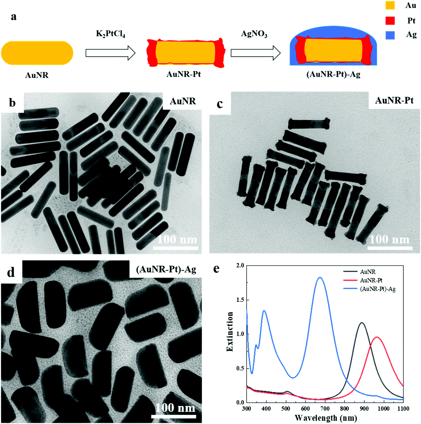 | ||
| Fig. 1 The TEM images of the experimental process and UV-vis-NIR extinction spectra. (a) The process of synthesizing the (AuNR–Pt)–Ag tri-metallic nanostructures. (b) The TEM image of AuNRs. The length of the AuNRs is 88.7 nm, the diameter is 17.1 nm, and the aspect ratio is about 5.2. (c) The TEM image of AuNR–Pt, and the lengths of AuNR–Pt (92.0 nm) are a little longer than AuNRs. The aspect ratio of the AuNR–Pt is about 5.3. (d) The TEM image of (AuNR–Pt)–Ag. Compared with AuNRs, the length of the AuNRs–Pt–Ag is about 99.1 nm and the diameter is about 47.3 nm. The core–shell nanostructures can be observed obviously and the aspect ratio is about 2.1. (e) The extinction spectra of AuNRs (black), AuNRs–Pt (red) and AuNRs–Pt–Ag (blue). The final nanoparticles are bigger than the original AuNRs. | ||
Fig. 1b–d shows the TEM images of AuNRs, AuNR–Pt, and (AuNR–Pt)–Ag nanostructures, respectively. The as-synthesized AuNRs with length L = 88.7 nm, diameter D = 17.1 nm, and the aspect ratio AR = 5.2 are shown in the Fig. 1b. When K2PtCl4 is added, a new product AuNR–Pt was obtained (Fig. 1c). According to Fig. 1c, one can find that major Pt reduced by the ascorbic acid was deposited on the ends of the AuNRs. The size parameters of AuNR–Pt are L = 90.5 nm, D = 17.1 nm, and AR = 5.3. The slight increase of the aspect ratio can be explained by the Pt deposited on the ends of AuNRs, which can increase the length of the AuNRs. For the AuNR–Pt, the Pt is discontinuously and roughly grown. Then, AgNO3 is added to synthesize the asymmetric (AuNR–Pt)–Ag trimetallic nanostructures, and continuous growth of a smooth Ag shell around the AuNR–Pt core can be observed, as shown in Fig. 1d. The size parameters are L = 99.3 nm, D = 47.3 nm, and AR = 2.1. The diameter of (AuNR–Pt)–Ag is much bigger than the original AuNRs, and the final products are asymmetric. The aspect ratio (AR = 2.1) decreases significantly compared to AuNRs (AR = 5.2) and AuNR–Pt (AR = 5.3).
Fig. 1e shows the UV-vis-NIR spectra of AuNR (black), AuNR–Pt (red), and (AuNR–Pt)–Ag (blue) nanostructures. The spectrum of original AuNRs has the longitudinal LSPR at 887 nm. After Pt deposition, the longitudinal LSPR has red-shifted to 964 nm and the LSPR intensity decreased. This is due to the increase of aspect ratio, and large plasmonic damping of Pt metal. Then, after Ag deposition, the longitudinal LSPR has blue-shifted to 675 nm, and the intensity of the LSPR increases significantly (∼2 times). In addition, the transverse LSPR of (AuNR–Pt)–Ag was shifted from ∼500 nm to ∼400 nm, and the intensity was quite pronounced. The change of LSPR properties could be ascribed to the higher LSPR energy on Ag, the decrease of the aspect ratio, and less plasmonic damping of Ag materials.
Using the high resolution transmission electron microscopy (HRTEM) images, we analyzed the crystalline structures of the asymmetric (AuNR–Pt)–Ag nanostructures. Fig. 2 shows a typical asymmetric (AuNR–Pt)–Ag nanostructure, where five different positions were chosen. The thicker side of the Ag shell is about 25.8 nm, while the thinner side is about 4.5 nm. Fig. 2b and c shows the thicker side of the asymmetric (AuNR–Pt)–Ag. The thicker side in Fig. 2b, clearly shows that the crystalline structure of Ag shell, the crystal plane spacing of Ag is measured to be 0.208 nm, which is a family of facets of Ag {100}. Fig. 2c and e shows the interface of Au and Ag. Since lattice constant of Au and Ag are nearly perfect matching, both images show the single crystalline structure (with same lattice space). In addition, the contrast of Au and Ag are different. The Au side is slightly darker than the Ag side, since the Au atom is heavier than that of the Ag. However, it's hard to find the interface in the images due to their single crystalline structure. In Fig. 2d and f, the area with red circles the lattices are vague and discontinuous, indicating the lattice mismatch and there should be the third metal Pt in the area of red circles. All the HRTEM images shown the same crystal plane spacing of {100} facets, indicating the Ag is epitaxially grown on the AuNR surface, while Pt is non-epitaxially grown.
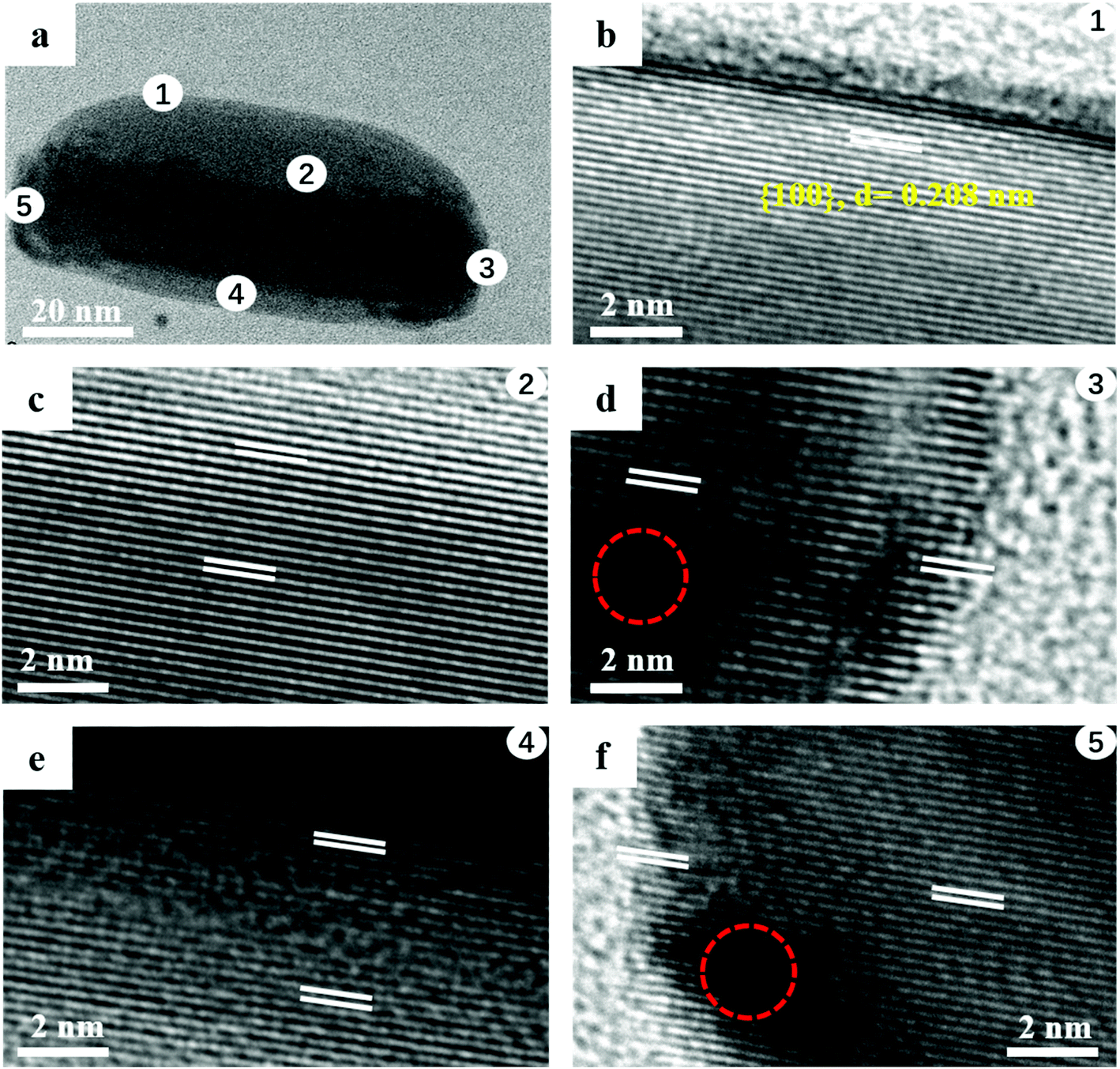 | ||
| Fig. 2 HRTEM images of the asymmetrical (AuNR–Pt)–Ag nanostructures. (a) TEM of a single (AuNR–Pt)–Ag. (b) The HRTEM image of the thicker side of the (AuNR–Pt)–Ag is shown in area 1 of (a). The crystal plane spacing of Ag is 0.208 nm, which is a family of faces at {100} facets. (c) The thicker side of the (AuNR–Pt)–Ag, which is shown in area 2 of the (a). There are two metals, Ag and Au. The bottom part is darker since Au atom is heavier than the Ag. Both the crystal plane spacing are {100} facets. (d) The right end of the (AuNR–Pt)–Ag shown in area 3. There are three metals, Au, Pt and Ag. The dark part in the red circle is Pt metal. (e) The thinner side of the (AuNR–Pt)–Ag in area 4 of (a). (f) The other end of the (AuNR–Pt)–Ag. Au shown in area 5, the black particles in this end are also Pt. | ||
To illustrate the elemental distribution of Au, Pt, and Ag metals, we performed the EDS spectrum to make out the elemental distribution of the three metals in a single tri-metallic structure. First, we give the dark-field TEM image of the single particle, it can be clearly observed that core–shell and asymmetric nanostructure in Fig. 3a and b. The white arrow indicates the direction of the line scan in Fig. 3a and b. The amount of Ag growing on both sides of AuNR–Pt is much greater than that on both ends of AuNR–Pt, and the amount of Ag growing on both sides is quite different. In Fig. 3c, the line scan in a long direction of the (AuNR–Pt)–Ag. We can see the distribution of the three metals along this direction. However, the Ag tends to overgrowth on one side of the AuNR–Pt (Fig. 3d). To visualize the distribution of the three metal elements, we show the EDS mapping in the Fig. S1.† The Au (yellow) is in the center of the nanostructure, and the Pt (red) mainly located in the two ends. However, the Ag is located all areas of the structure. Dynamic light scattering (DLS) tests were performed to determine the stability of the solution from a microscopic perspective. In Fig. S2,† we measured zeta potential of the asymmetric (AuNR–Pt)–Ag nanostructures. Fig. S2† shows the zeta-potential of the solution is greater than +30 mV, indicating the whole system is quite stable due to the CTA+ species in the solution. We can speculate that the resulting tri-metallic nanostructures has a lot of CTA+ attached to the surface, thus the nanoparticles are positively charged.
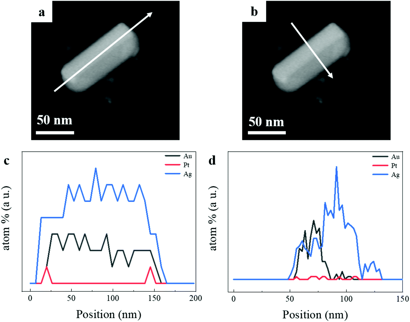 | ||
| Fig. 3 The EDS spectrum of the (AuNR–Pt)–Ag. (a and b) Dark-field TEM image of a single (AuNRs–Pt)–Ag, the core–shell nanostructure can be observed. White arrows indicate the scanning directions of the EDS spectrum. (c) The EDS spectrum of the line scan in a longitudinal direction of the single (AuNR–Pt)–Ag. The Pt mainly deposited in the ends of the AuNR. (d) The EDS spectrum of the line scan along a transverse line. The amount of the Pt is quite small, while the Ag mainly deposited in the sides of the AuNR–Pt and tends to overgrowth in one side. | ||
To determine the effect of AgNO3 concentration in the asymmetric growth, control experiments with different AgNO3 amounts were conducted. The results were shown in Fig. 4, 5 and Table 1. Fig. 4a shows the UV-vis-NIR extinction spectra of (AuNR–Pt)–Ag with different amount of AgNO3 (0.2–1.0 mL). With the increase of AgNO3, the position of the LSPR peak is gradually blue-shifted, and the intensity of LSPR peak is increased. The change of the LSPRs were also indicated by the color change of the solution. Fig. 4b shows the physical optical images of different AgNO3. The color of the resulting solution gradually changed from brownish to greenish. ICP-MS were performed and the results were shown in Fig. S3.† W% represents the weight proportion of each element in the tri-metallic structure. When the amounts of AgNO3 is 0.2 mL, the content of Au can reach 94.8%, at this point, the amount of Ag is only about 4.1%. When the amount of AgNO3 continue to increase, there will be asymmetric structure, at this time, the content of Au element will drop to about 50%, while the content of Ag element will rise to about 50%. However, in the five groups of samples, the content of platinum is always very low (less than 1%).
 | ||
| Fig. 4 The UV-vis-NIR extinction spectra and TEM images of (AuNR–Pt)–Ag with different amount of AgNO3. (a) The UV-vis-NIR extinction spectra of (AuNR–Pt)–Ag with different amount of 4.0 mM AgNO3 (0.2–1.0 mL). (b) The physical optical images of the final experimental resulted (AuNR–Pt)–Ag nanostructures. From left to right, the amount of AgNO3 precursor are 0.2 mL, 0.4 mL, 0.6 mL, 0.8 mL and 1.0 mL, respectively. The color of the solution changed from brownish to greenish gradually. (c–f) TEM images of the addition of AgNO3 with (c) 0.2 mL, (d) 0.4 mL, (e) 0.6 mL, and (f) 0.8 mL. When the amount of AgNO3 increased, the particle become bigger and asymmetric. | ||
 | ||
| Fig. 5 The size, aspect ratio, LSPR and yield of asymmetric nanostructures with different amount of 4.0 mM AgNO3 (0.2–1.0 mL). (a) The size of final products with different amount of AgNO3. Especially, 0 mL of AgNO3 corresponds to the sample AuNR–Pt. With the increase of AgNO3 amount, the particles become bigger and the diameter increased faster than the length. (b) The aspect ratio of different products. With the increase of AgNO3, the aspect ratio decreased. (c) The position of LSPR in different (AuNR–Pt)–Ag. As the amount of AgNO3 increased, the position of the LSPR gradually blue-shifted. (d) The yield of asymmetric (AuNR–Pt)–Ag. The core–shell structures cannot be observed with 0.2 mL AgNO3. Especially, when the amount of AgNO3 is 1.0 mL, the yield of asymmetric nanostructures can reach >99%. | ||
| Sample | Length (nm) | Diameter (nm) | Aspect ratio | LSPR (nm) | Yield of asymmetric AuNRs–Pt–Ag |
|---|---|---|---|---|---|
| AuNRs | 88.7 ± 7.0 | 17.1 ± 1.7 | 5.2 ± 0.6 | 887 | — |
| AuNRs–Pt | 90.5 ± 5.0 | 17.1 ± 1.1 | 5.3 ± 0.5 | 964 | — |
| AuNRs–Pt–Ag (0.2 mL) | 88.8 ± 6.6 | 16.8 ± 1.7 | 5.3 ± 0.8 | 792 | 0 |
| AuNRs–Pt–Ag (0.4 mL) | 94.8 ± 6.4 | 24.8 ± 2.7 | 3.8 ± 0.5 | 777 | 18% |
| AuNRs–Pt–Ag (0.6 mL) | 97.4 ± 7.8 | 29.6 ± 2.8 | 3.3 ± 0.4 | 731 | 66% |
| AuNRs–Pt–Ag (0.8 mL) | 99.3 ± 7.6 | 33.1 ± 2.7 | 3.0 ± 0.4 | 698 | 93% |
| AuNRs–Pt–Ag (1.0 mL) | 99.3 ± 8.0 | 47.3 ± 3.4 | 2.1 ± 0.2 | 675 | >99% |
In order to observe the change of tri-metallic structure from symmetric to asymmetric from microscopic point of view, we made TEM images of (AuNRs–Pt)–Ag with different AgNO3. In Fig. 4c, when the measured addition of AgNO3 is 0.2 mL, the aspect ratio is same as the AuNR–Pt (5.3). There is no obvious Ag shell can be observed. When the amount of AgNO3 is increased to 0.4 mL, the (AuNR–Pt)–Ag mainly tends to have a symmetrical structure, and the Ag shell mainly grows symmetrically (Fig. 4d), and only 18% (AuNR–Pt)–Ag in asymmetric structure (Table 1). 0.6 mL of AgNO3 is shown in the Fig. 4e, the proportion of asymmetrical structures decreased gradually, and proportion is 66%, while the proportion of symmetrical (AuNR–Pt)–Ag increased greatly. However, when 0.8 mL AgNO3 is added, the (AuNR–Pt)–Ag are in both symmetric and asymmetric (Fig. 4c), and the proportion of the asymmetric structures is 93% (Table 1). It can be seen that when the amount of AgNO3 gradually increases, the proportion of asymmetrical structure gradually increases (Table 1). It turned out that only the amount of AgNO3 corresponding to the AuNR–Pt seeds can grow the asymmetric tri-metal structures. Which can also be compared with the results of the ICP-MS test. We further explore the influencing factors of symmetric and asymmetric growth. As researched shown before, the symmetric and asymmetric growth of the AuNR–Ag depends on the pH of the growing solution.34 However, in our research, the structures of the final (AuNR–Pt)–Ag are sensitive to the ratio of the amount of the seeds to the amount of the AgNO3. In Fig. 5, we give the tendency of the size, aspect ratio, LSPR and the yield of the asymmetric nanostructures. With the increase of AgNO3, the size of the final tri-metallic nanostructures became bigger (Fig. 5a), and the tendency of the aspect ratio is decreasing (Fig. 5b), which can be illustrated the LSPR peak have blue-shifted, and the intensity enhanced (Fig. 5c). Because the core–shell nanostructures with 0.2 mL AgNO3 cannot be seen in the TEM image in Fig. 4c, the yield of the asymmetric nanostructures is 0. In Fig. 5d, with the increase of the amount of AgNO3, the ratio of asymmetric tri-metallic nanostructures gradually increased.
Due to the various morphology formed in the Pt and Ag overgrowth, we investigated the mechanism of overgrowth based on crystal growth theory. There are three types of growth modes, that is the island growth mode (Volmer Weber, V&W), the layer-by-layer growth mode (Frank van der Merwe, F&M), and the intermediate growth mode (Stranski Krastanov, S&K).35,36 Herein, we observed discontinuous, rough and nonepitaxial growth of Pt on AuNRs, which is suit in V&W mode. Whereas, epitaxial and continuous growth of Ag on AuNR–Pt is matched with F&M mode. These three growth modes are mainly determined by two factors as follows: (1) surface energies (ES). The ES values for Au, Ag and Pt are 1.50 J m−2, 1.24 J m−2 and 2.49 J m−2 (ref. 37) in Table 2.38 Previous studies have shown that the ES (Pt) > ES (Au) and the bond dissociation energies between the same Pt is bigger than that of Au and Pt, the discontinuous, rough, non-epitaxial shell growth is indeed expected. Similarly, ES (Ag) < ES (Au) and the bond dissociation energies between Ag–Ag is smaller than that of Au–Ag. So the smooth, continuous, epitaxial Ag shell growth was observed.38 And our experimental results also coincide with these facts, as shown in Fig. 1c and d. (2) the lattice mismatch between the substrate metal and the second metals regrowth on top of the substrate metals. The face centered cubic (FCC) lattice constant of Au is 4.08 Å, and Pt is 3.92 Å, the FCC lattice constants of these two metals are not well matched. That's why Pt deposited in the AuNRs discontinuously. The FCC lattice constant of Ag (4.09 Å) nearly perfectly matches with the lattice constant of Au and quite different from that of Pt, which can be explained why Ag tends to epitaxially grow mainly on the sides of AuNRs–Pt seeds and the amount of Ag deposited in the ends of the AuNR–Pt is quite little. Compared to the research before, when there is no Pt in the ends of the AuNR, the Ag deposited in the all areas of the AuNR and overgrowth a symmetric core–shell nanostructure.27
| Au | Pt | Ag | |
|---|---|---|---|
| FCC lattice constant (Å) | 4.08 | 3.92 | 4.09 |
| Surface energy, ES (J m−2) | 1.50 | 2.49 | 1.24 |
| Bond dissociation energy M–M, ED(M–M) (kJ mol−1) | 226 | 307 | 160 |
| Bond dissociation energy, ED(Au–M) (kJ mol−1) | 226 | — | 203 |
In order to better understand and determine the reasons for the asymmetric growth pf Ag, we give the reaction mechanism39 of the whole experimental process:
| Au3+ + C6H8O6 → Au+ + C6H6O6 + 2H+ |
| 2Au+ + C6H8O6 → 2Au + C6H6O6 + 2H+ |
| 2Ag+ + C6H8O6 → 2Ag + C6H6O6 + 2H+ |
Therefore, the amount of reduced Au is about 60%, and is about 0.32 mM. In our method, the solution of AuNRs is 0.5 mL, and 1.0 mL of 2.0 mM K2PtCl4 is added for heating 90 min, where the Pt2+ is not reduced completely. Here, when Au![[thin space (1/6-em)]](https://www.rsc.org/images/entities/char_2009.gif) :Pt is about 2:25, the Pt2+ can deposit on the ends of the AuNRs. And then, we took 0.5 mL AuNRs–Pt and 1.0 mL 4.0 mM AgNO3 to synthesize the AuNRs–Pt–Ag. So Au:Pt:Ag = 2:25:50. At this quantity ratio, the asymmetric structures of these three metals can be grown to the greatest extent. When the AuNRs–Pt:AgNO3 = 1:2, the Ag can grow in asymmetric on two sides. And when the ratio is smaller than 0.5, the ratio of asymmetric structure is decreased. Especially, when the ratio is about 2.5, there is no asymmetric products and no core–shell structures can be observed. Compared to the previous research,34 which control the morphology by control the pH of the solution. We control the morphology of the final nanostructures by controlling the ratio of AuNR–Pt seeds to the amount of AgNO3. When the ratio of the AuNR–Pt to the AgNO3 decreasing, the yield of asymmetric nanostructures increasing (Table 1). However, when the addition of the 4.0 mM AgNO3 is 0.2 mL, the core–shell nanostructures cannot be observed obviously, that is to say, the yield of the asymmetric nanostructures is 0. Therefore, for the corresponding amount of the AuNR–Pt seeds used in our method, 0.2 mL of 4.0 mM AgNO3 is a critical value. As long as the amount of AgNO3 is greater than this threshold, asymmetric (AuNR–Pt)–Ag nanostructures are produced. As for mechanism of asymmetric growth, the most probable reason is the different deposition rate of Ag on both sides of the AuNR–Pt seed.
:Pt is about 2:25, the Pt2+ can deposit on the ends of the AuNRs. And then, we took 0.5 mL AuNRs–Pt and 1.0 mL 4.0 mM AgNO3 to synthesize the AuNRs–Pt–Ag. So Au:Pt:Ag = 2:25:50. At this quantity ratio, the asymmetric structures of these three metals can be grown to the greatest extent. When the AuNRs–Pt:AgNO3 = 1:2, the Ag can grow in asymmetric on two sides. And when the ratio is smaller than 0.5, the ratio of asymmetric structure is decreased. Especially, when the ratio is about 2.5, there is no asymmetric products and no core–shell structures can be observed. Compared to the previous research,34 which control the morphology by control the pH of the solution. We control the morphology of the final nanostructures by controlling the ratio of AuNR–Pt seeds to the amount of AgNO3. When the ratio of the AuNR–Pt to the AgNO3 decreasing, the yield of asymmetric nanostructures increasing (Table 1). However, when the addition of the 4.0 mM AgNO3 is 0.2 mL, the core–shell nanostructures cannot be observed obviously, that is to say, the yield of the asymmetric nanostructures is 0. Therefore, for the corresponding amount of the AuNR–Pt seeds used in our method, 0.2 mL of 4.0 mM AgNO3 is a critical value. As long as the amount of AgNO3 is greater than this threshold, asymmetric (AuNR–Pt)–Ag nanostructures are produced. As for mechanism of asymmetric growth, the most probable reason is the different deposition rate of Ag on both sides of the AuNR–Pt seed.
3. Conclusions
In summary, we have successfully synthesized symmetric and asymmetric (AuNR–Pt)–Ag tri-metallic nanostructures by a 2-step seed-mediated method. The Pt pre-deposition on the ends of AuNRs is crucial for the way of Ag overgrowth on the surface of the AuNRs, which can control the morphology of the resulted nanostructure. The shell thickness of Ag and symmetry of final products could be simply controlled by the AgNO3 precursor concentration. By increasing the AgNO3, we can obtain the tri-metallic structure from symmetric to asymmetric. And the yield of the asymmetric (AuNR–Pt)–Ag core–shell nanostructures can be controlled by the ratio of AuNR–Pt seeds to the amount of AgNO3. The obtained (AuNR–Pt)–Ag shows two peaks with a wavelength at 300–500 nm, and possesses longitudinal LSPR peak in about 700 nm. This growth method provides a possible way to utilize K2PtCl4 for controlling the morphology of the Au–Ag core–shell nanostructures from symmetric to asymmetric. What's more, the obtained (AuNR–Pt)–Ag shows not only shape evolution but also a controllable longitudinal LSPR peak shift, which could be applied in tunable wavelength enhanced photocatalytic reaction. Besides, due to the Ag shell of the final tri-metallic structure, this (AuNR–Pt)–Ag may have significant surface Raman enhancement. And we also provide a possible method to combine three metals to form different morphology and shapes.4. Experimental section
Materials
All chemicals were used as received without further purification. Hexadecyltrimethylammonium bromide (CTAB, >99.0%), L-ascorbic acid (AA, >99.99%), chloroauric acid (HAuCl4), and hydrochloric acid (HCl, 37 wt% in water) were purchased from Macklin. Hexadecyltrimethylammonium chloride (CTAC, >99.0%), sodium borohydride (NaBH4, 98%), sodium oleate (NaOL, >99.88%), silver nitrate (AgNO3, >99.8%), potassium tetrachloroplatinate(II) (K2PtCl4, >99.99%) were purchased from Aladdin. Ultrapure water (Millipore Milli-Q grade) with a resistivity of 18.2 MΩ was used in all of the experiments. All glassware for the AuNRs synthesis were cleaned with freshly prepared aqua regia (HCl/HNO3 in a 3:1 volume ratio), rinsed with large amounts of water, and dried in oven at 60 °C before use.
Synthesis of gold nanorods (AuNRs)
AuNRs with an aspect ratio of 5.2 were prepared by following a seed-mediated growth procedure previously reported by Murray et al.4 Briefly, the seed solution was prepared as follows: firstly, 0.25 mL 10 mM HAuCl4 was added to 10 mL 0.1 M CTAB solution. Then 0.6 mL 10 mM NaBH4 (freshly prepared with cold water) was quickly added to the solution under the vigorous stirring (1200 rpm) and was stopped after 2 min. The color of the solution changed from yellow to brownish yellow. Finally, the seed solution was aged at room temperature for at least 30 min before use.To prepare the growth solution, 7.0 g (37 mM in the final growth solution) of CTAB and 1.234 g NaOL were mixed in 250 mL of warm water (∼50 °C). 18.0 mL 4.0 mM AgNO3 was added to the solution and kept undisturbed at 30 °C for 15 min. Afterward, 25.0 mL 10.0 mM of HAuCl4 solution and 225 mL water were added and stirred at 700 rpm. The result solution became colorless after 90 min. Then 2.1 mL of HCl (37 wt% in water) was dropwise added and stirred at 700 rpm for 15 min. After 15 min, 1.25 mL 64.0 mM of AA was added to the solution above and kept vigorously stirring for 30 s before the addition of 0.8 mL of the seed solution. The resulted mixture was stirred for 30 s and left undisturbed at 30 °C overnight for AuNRs growth.
Synthesis of AuNR–Pt nanostructures
The as-prepared AuNRs solution were about 500 mL. Then the AuNRs were washed twice by centrifugation at 7000 rpm for 30 min followed by removal of the supernatant. And the result solution (concentrated 11 times) was kept in 2.0 mM of CTAB as the stock solution before use. To deposit Pt on AuNRs, 0.5 mL of the AuNRs stock solution was added to the mixed solution, which contains 2.2 mL 0.1 M of CTAB and 17.8 mL deionized water. Then, 0.25 mL 4.0 mM of AgNO3 and 1.0 mL 2.0 mM of K2PtCl4 were added into the solution above. We measured the extinction spectra of the solution as this point, and the longitudinal LSPR is 964 nm with intensity of 1.04. Then the mixed solution was heated in a 80 °C water bath for 90 min. The resulted solution was washed twice by centrifugation at 7000 rpm for 30 min followed by removal of the supernatant.Synthesis of (AuNR–Pt)–Ag core–shell nanostructures
The purified AuNR–Pt (0.5 mL) were used as seeds and added into 17.0 mL 30.0 mM of CTAC and stirred at 400 rpm in 60 °C water bath for 20 min. The extinction spectrum of the solution was measured, and the longitudinal LSPR is about 675 nm with intensity of 1.75. Then 1.0 mL 0.1 mM of AA (in 30.0 mM CTAC) and 1.0 mL 4.0 mM AgNO3 were simultaneously injected with a syringe pump at a speed rate of 0.5 mL min−1. The solution was kept in a 60 °C water bath for 40 min. The final solution was collected after two times of centrifugation at 7000 rpm for 30 min. To control the Ag shell thickness, we carried out a series of control experiments by changing the amount of AgNO3 precursor. The detailed experimental parameters were listed in Table 1.Characterization
Optical extinction spectra were recorded with a UV-1900i spectrophotometer (SHIMADZU, Japan) with a 10.0 mm optical path. The transmission electron microscope (TEM) images were obtained with a HT-7700 microscope (HITACHI, Japan) operating at 100 kV. High resolution TEM (HRTEM) images and energy disperse spectroscopy (EDS) mapping were performed using a JEM 2100F TEM with a 200 kV acceleration voltage. The particle sizes of the nanoparticles were measured from TEM images, whereby >100 nanoparticles were measured for each sample. The DLS measurements (zeta-potential) of the (AuNR–Pt)–Ag were performed at Malvern Zetasizer Nano ZS90 and ICP-MS were performed at Aglient 7800. We measured DLS of the sample of asymmetrical nanostructures with 0.2 mL AgNO3, which were added 1 mL aqua regia to dissolve this tri-metallic nanostructure and the final solution was diluted to 5 mL. Meanwhile, the test of the ICP-MS was performed in the same way of DLS. The solution used for both DLS and ICP-MS tests was 100 times diluted compared to that eventually synthesized the tri-metallic nanostructures.Conflicts of interest
There are no conflicts to declare.Acknowledgements
We thank Ms Sudan Shen for electron microscopy support, and the authors acknowledge financial support from the National Natural Science Foundation of China (NSFC, Grant no. 61905056) and Zhejiang Provincial Natural Science Foundation of China (Grant no. LY19E020011).References
- Q. K. Fan, K. Liu, J. Feng, F. M. Wang, Z. J. Liu, M. X. Liu, Y. D. Yin and C. B. Gao, Adv. Funct. Mater., 2018, 28, 1803199 CrossRef.
- H. Jang, S. Ham, J. Acapulco, Y. Song, S. Hong, K. Shuford and S. Park, J. Am. Chem. Soc., 2014, 136, 17674–17680 CrossRef CAS PubMed.
- S. Ding, H. Zhang, D. Yang, Y. Qiu, F. Nan, Z. Yang, J. Wang, Q. Wang and H. Lin, Nano Lett., 2019, 19, 2005–2011 CrossRef CAS PubMed.
- X. C. Ye, C. Zheng, J. Chen, Y. Z. Gao and C. B. Murray, Nano Lett., 2013, 13, 765–771 CrossRef CAS PubMed.
- K. K. Jesna and M. Ilanchelian, New J. Chem., 2020, 44, 20574–20583 RSC.
- E. Darrigues, Z. A. Nima, D. A. Nedosekin, F. Watanabe, K. M. Alghazali, V. P. Zharov and A. S. Biris, Sci. Rep., 2020, 10, 3362–3376 CrossRef CAS PubMed.
- C. Murphy, H. Chang, P. Falagan-Lotsch, M. Gole, D. Hofmann, K. Hoang, S. McClain, S. Meyer, J. Turner, M. Unnikrishnan, M. Wu, X. Zhang and Y. Zhang, Acc. Chem. Res., 2019, 52, 2124–2135 CrossRef CAS PubMed.
- Z. X. He, C. S. Li, H. D. Robinson and Y. Z. Zhu, Nanoscale, 2020, 12, 2613–2625 RSC.
- H. Huang, X. Liu, Y. Zeng, X. Yu, B. Liao, P. Yi and P. K. Chu, Biomaterials, 2009, 30, 5622–5630 CrossRef CAS PubMed.
- C. G. Yang, X. F. Tao, Y. Yang and K. Liu, Chem. Commun., 2020, 56, 1677–1680 RSC.
- H. J. Kim, M. M. Hossen, A. C. Hillier, D. Vaknin, S. K. Mallapragada and W. J. Wang, ACS Appl. Nano Mater., 2020, 3, 8216–8223 CrossRef CAS.
- C. Han, M. Qi, Z. Tang, J. Gong and Y. Xu, Nano Today, 2019, 27, 48–72 CrossRef CAS.
- W. Xiong, D. Sikdar, L. W. Yap, P. Z. Guo, M. Premaratne, X. Y. Li and W. L. Cheng, Nano Res., 2016, 9, 415–423 CrossRef CAS.
- Y. M. Ou, L. Pei, K. Q. Lai, Y. Q. Huang, B. A. Rasco, X. H. Wang and Y. X. Fan, Food Anal. Methods, 2017, 10, 565–574 CrossRef.
- F. K. Alsammarraie and M. S. Lin, J. Agric. Food Chem., 2017, 65, 666–674 CrossRef CAS PubMed.
- S. Jeong, S. Y. Lee, M. W. Kim and J. H. Kim, Appl. Surf. Sci., 2021, 543, 148831–148837 CrossRef CAS.
- J. K. Majhi and P. K. Kuiri, J. Nanopart. Res., 2020, 22, 86 CrossRef CAS.
- S. Salimian and H. Soofi, Opt. Appl., 2020, 50, 343–355 CAS.
- J. Zhu, J. Wang, J. Li and J. Zhao, Sens. Actuators, B, 2016, 233, 214–222 CrossRef CAS.
- T. T. Li, H. Yi, Y. Liu, Z. L. Wang, S. Q. Liu, N. Y. He, H. N. Liu and Y. Deng, J. Biomed. Nanotechnol., 2018, 14, 150–160 CrossRef CAS PubMed.
- A. Verdin, C. Malherbe, W. H. Muller, V. Bertrand and G. Eppe, Anal. Bioanal. Chem., 2020, 412, 7739–7755 CrossRef CAS PubMed.
- I. Lee, R. Morales, M. A. Albiter and F. Zaera, Proc. Natl. Acad. Sci. U. S. A., 2008, 105, 15241–15246 CrossRef CAS PubMed.
- T. S. Deng, J. E. S. van der Hoeven, A. O. Yalcin, H. W. Zandbergen, M. A. van Huis and A. van Blaaderen, Chem. Mater., 2015, 27, 7196–7203 CrossRef CAS.
- F. Xie, W. Ye, H. Y. Sun, S. F. Kou and X. Guo, Langmuir, 2015, 31, 6823–6828 CrossRef CAS PubMed.
- M. Mirdamadi-Esfahani, M. Mostafavi, B. Keita, L. Nadjo, P. Kooyman and H. Remita, Gold Bull., 2010, 43, 49–56 CrossRef CAS.
- Y. L. Zhang, X. K. Li, K. Li, B. Xue, C. M. Zhang, C. Du, Z. J. Wu and W. Chen, ACS Appl. Mater. Interfaces, 2017, 9, 32688–32697 CrossRef CAS PubMed.
- I. Haidar, A. Day, P. Decorse, S. Lau-Truong, A. Chevillot-Biraud, J. Aubard, N. Felidj and L. Boubekeur-Lecaque, Chem. Mater., 2019, 31, 2741–2749 CrossRef CAS.
- S. L. Ke, C. X. Kan, X. Z. Zhu, C. S. Wang, X. Wang, Y. Chen, X. G. Zhu, Z. S. Li and D. N. Shi, CrystEngComm, 2021, 23, 3467–3476 RSC.
- J. Zhu, J.-J. Li and J.-W. Zhao, Plasmonics, 2015, 10, 1–8 CrossRef.
- J. Yan, Y. D. Chen, S. Hou, J. Q. Chen, D. J. Meng, H. Zhang, H. Z. Fan, Y. L. Ji and X. C. Wu, Nanoscale, 2017, 9, 11093–11102 RSC.
- L. W. Dai, L. P. Song, Y. J. Huang, L. Zhang, X. F. Lu, J. W. Zhang and T. Chen, Langmuir, 2017, 33, 5378–5384 CrossRef CAS PubMed.
- S. Jessl, M. Tebbe, L. Guerrini, A. Fery, R. A. Alvarez-Puebla and N. Pazos-Perez, Small, 2018, 14, 1703879 CrossRef PubMed.
- K. Karn-orachai, K. Sakamoto, R. Laocharoensuk, S. Bamrungsap, T. Dharakul and K. Miki, RSC Adv., 2017, 7, 14099–14106 RSC.
- S. Ding, D. Yang, X. Liu, F. Nan, Z. Cheng, S. Im, L. Zhou, J. Wang and Q. Wang, Nano Res., 2018, 11, 686–695 CrossRef CAS.
- F. Fan, D. Liu, Y. Wu, S. Duan, Z. Xie, Z. Jiang and Z. Tian, J. Am. Chem. Soc., 2008, 130, 6949–6951 CrossRef CAS PubMed.
- E. Bauer and J. H. van der Merwe, Phys. Rev. B: Condens. Matter Mater. Phys., 1986, 33, 3657–3671 CrossRef CAS PubMed.
- W. R. Tyson and W. A. Miller, Surf. Sci., 1977, 62, 267–276 CrossRef CAS.
- J. E. S. van der Hoeven, T.-S. Deng, W. Albrecht, L. A. Olthof, M. A. van Huis, P. E. de Jongh and A. van Blaaderen, ACS Omega, 2021, 6, 7034–7046 CrossRef CAS PubMed.
- J. A. Edgar, A. McDonagh and M. Cortie, ACS Nano, 2012, 6, 1116–1125 CrossRef CAS PubMed.
Footnote |
| † Electronic supplementary information (ESI) available. See DOI: 10.1039/d1ra07415f |
| This journal is © The Royal Society of Chemistry 2021 |