
 Open Access Article
 This Open Access Article is licensed under a Creative Commons Attribution-Non Commercial 3.0 Unported Licence
N and S co-doped graphene enfolded Ni–Co-layered double hydroxides: an excellent electrode material for high-performance energy storage devices†
Firoz Khan *
*
Interdisciplinary Research Center for Renewable Energy and Power Systems (IRC-REPS), Research Institute, King Fahd University of Petroleum & Minerals (KFUPM), Dhahran-31261, Saudi Arabia. E-mail: firoz.khan@kfupm.edu.sa; Fax: +966 13 8607312; Tel: +966 13 8607019
First published on 18th October 2021
Abstract
The performance of hybrid supercapacitors (HSCs) can be increased via the selection of higher capacitive electrode materials. Thus, layered double hydroxides (LDHs) have received extensive consideration in HSCs owing to their good ion-exchange properties, structural flexibility, and large specific surface area. Ni–Co-based LDHs show better specific capacitance, good synergy, and high-rate capability in aqueous electrolytes. However, LDHs suffer from low conductivity, which curbs the charge transfer and mass diffusion throughout the electrochemical process. Thus, the high performance of LDH-based supercapacitors is impeded. Hence, composites of LDH and conducting materials are used. Owing to its extraordinary conducting property, huge surface area, and cost-effectiveness, reduced graphene oxide (rGO) is used as conducting material for LDH-based composite electrodes. Moreover, via the incorporation of heteroatoms (N, S, etc.) into rGO, its electrochemical properties are further enhanced. Here, a novel composite electrode is prepared by wrapping Ni–Co-LDH with N and S-co-doped rGO (LDH-rGO-NS) via a hydrothermal process. The XPS C 1s spectra established the existence of N and S doping in the rGO. The electrochemical performance is enhanced due to an excellent ion/charge transfer rate because of N and S co-doping. The LDH-rGO-NS electrode offers a good charge transfer resistance of 0.24 Ω. The obtained anodic and cathodic b-values are 0.73 and 0.72, respectively. An admirable specific capacitance of 1388 F g−1 is accomplished at a sweep rate of 100 mV s−1. Furthermore, the obtained retention capacity is ∼71% after 2000 cycles. Moreover, the achieved specific capacitance is 2193 F g−1 at the discharge current density of 5 A g−1. The excellent electrochemical properties reveal the LDH-rGO-NS composites as encouraging electrode materials for HSCs.
1. Introduction
Storing electrical energy is critical for addressing issues related to environmental protection, renewable energy integration, energy sustainability, energy efficiency, and so on.1,2 Amongst the available electrical energy storing machinery, supercapacitors (SCs) are appropriate for several important applications where prompt power supply and a long-lasting lifetime are essential. SCs possess high power density along with a prolonged life cycle. They also ensure enhanced safety to modern electronic appliances. However, their energy density is quite low in comparison to batteries/fuel cells due to the inherent problem of the two main classes of supercapacitors i.e., electric double-layer capacitors (EDLCs) and pseudocapacitors (PSCs). To increase the power density along with the energy density, a hybrid structure has been evolved by combining the EDLC and PSC principles into its architecture. Thus, the obtained devices by combining the properties of EDLCs and PSCs are known as hybrid supercapacitors (HSCs). They retain high energy densities in addition to high power densities unlike normal SCs.3–7 In the present scenario of high-tech electronics and electricity demand, HSCs have arisen as prominent energy storage devices (ESDs) to fulfill the demand of energy scarceness, safety, and security. Owing to their huge potential in electricity storage, portable electronics, and hybrid vehicles, this technology has received substantial consideration by researchers to improve their performance. Moreover, owing to their great performance, prolonged life cycle, tremendous cyclic stability, and ecological friendliness, HSCs are considered promising ESDs. Among the different components of HSCs, the electrode materials directly affect electrochemical performance. The nature and performance of the electrode materials are the basic keys to develop high-performance HSCs with an elongated life cycle along with high energy/power densities.3,4,6–9 In conventional HSCs, carbon-based materials are used as a negative electrode (anode during discharge process), while metal compounds (oxides, hydroxides, layered double hydroxide (LDH), metal–metal oxides (MMO)) are used as the positive electrode (cathode during discharge process).3–8,10 In the past few years, LDHs have received extensive consideration as the anode materials in HSCs owing to their good ion-exchange property, structural flexibility, and huge surface area. The manifold oxidation state LDH is the additional advantage to enhance the performance HSCs. Among the LDHs, Ni–Co-based LDHs (Ni–Co-LDH) showed superior specific capacitance, good synergy, and high-rate capability. Moreover, the microstructure of these materials can be controlled during the synthesis process, which provides greater flexibility to tune the size and structure of LDHs. Another important factor that is essential to control the structural and morphological properties accompanied by crystallinity and capacity of these bi-metallic LDHs is the atomic ratio of the metallic elements. Several researchers studied the influence of the Ni and Co fraction in Ni–Co-LDH. Sun et al.11 reported having nanosheets (1![[thin space (1/6-em)]](https://www.rsc.org/images/entities/char_2009.gif) :1), nanoplates (1:2), and nanorods (1:4) of Ni–Co-LDHs through the variation of Ni and Co composition. Yang et al.12 have investigated the dependency of the LDH microstructure on Ni/Co ratio. They have found that nanowire-shaped Ni–Co-LDH was obtained at a 1:1 Ni:Co ratio, which disappeared with the reduction of Co content. In another report, Wu et al.6 have prepared Ni–Co-LDHs and nitrogen-doped CNT composite electrodes on Ni foam using different Ni and Co compositional ratios. They have obtained the best capacitance value of 2170 F g−1 for Ni and Co atomic ratio of 1:1 at 1 A g−1. However, the best cycle constancy was achieved for the Ni and Co atomic ratio of 67:33 (approximately 2:1). Moreover, like all other LDH materials, Ni–Co-based LDH also endures from low conductivity, thus the charge transfer, as well as mass diffusion, is hampered during the charge/discharge cycling. Thus, the LDH-based HSCs offer a low value of capacitance. Furthermore, the agglomeration in the LDH nanostructures has also been observed, which obstructs the energy density and degrades the cycling constancy of the HSCs. Thus, a composite of conducting material (carbon nanotubes, carbon nanofiber, conducting carbon, graphene, etc.) and LDH is used or LDH is directly deposited on nickel foam to overcome this particular issue.3–6 This approach was found to be effective to enhance the electronic conductivity, which consequences in a better rate of competence, and improved cycling constancy of Ni–Co-LDH. Among all these conductive substrates used to overcome the low conductivity issues of the LDHs, graphene-based composites showed superior performances.13–16 It is due to graphene's outstanding electrical and thermal conductivity, high mechanical strength, and high specific surface area. Several research groups observed that the graphene's properties can be further twined to enhance its performance, simply by doping and/or co-doping with some heteroatoms, for example, N, S, P, or B. In particular, the co-doping of graphene is getting attention because it can create a unique and synergistically coupled electronic structure.7,13–17 To reduce the energy-storing cost and minimize the size of the HSCs, the electrochemical performance of the anode materials further needs to be improved.
:1), nanoplates (1:2), and nanorods (1:4) of Ni–Co-LDHs through the variation of Ni and Co composition. Yang et al.12 have investigated the dependency of the LDH microstructure on Ni/Co ratio. They have found that nanowire-shaped Ni–Co-LDH was obtained at a 1:1 Ni:Co ratio, which disappeared with the reduction of Co content. In another report, Wu et al.6 have prepared Ni–Co-LDHs and nitrogen-doped CNT composite electrodes on Ni foam using different Ni and Co compositional ratios. They have obtained the best capacitance value of 2170 F g−1 for Ni and Co atomic ratio of 1:1 at 1 A g−1. However, the best cycle constancy was achieved for the Ni and Co atomic ratio of 67:33 (approximately 2:1). Moreover, like all other LDH materials, Ni–Co-based LDH also endures from low conductivity, thus the charge transfer, as well as mass diffusion, is hampered during the charge/discharge cycling. Thus, the LDH-based HSCs offer a low value of capacitance. Furthermore, the agglomeration in the LDH nanostructures has also been observed, which obstructs the energy density and degrades the cycling constancy of the HSCs. Thus, a composite of conducting material (carbon nanotubes, carbon nanofiber, conducting carbon, graphene, etc.) and LDH is used or LDH is directly deposited on nickel foam to overcome this particular issue.3–6 This approach was found to be effective to enhance the electronic conductivity, which consequences in a better rate of competence, and improved cycling constancy of Ni–Co-LDH. Among all these conductive substrates used to overcome the low conductivity issues of the LDHs, graphene-based composites showed superior performances.13–16 It is due to graphene's outstanding electrical and thermal conductivity, high mechanical strength, and high specific surface area. Several research groups observed that the graphene's properties can be further twined to enhance its performance, simply by doping and/or co-doping with some heteroatoms, for example, N, S, P, or B. In particular, the co-doping of graphene is getting attention because it can create a unique and synergistically coupled electronic structure.7,13–17 To reduce the energy-storing cost and minimize the size of the HSCs, the electrochemical performance of the anode materials further needs to be improved.
2. Objectives
The objective of the work is to develop an advanced electrode material for a high-performance electrochemical energy storage device. It is observed that Ni–Co-based LDH offers superior specific capacitance, excellent interaction, and high cycling performance. Due to the low conductivity of Ni–Co-LDH, the electrochemical performance of Ni–Co-LDH based electrodes is hampered. Thus, it creates an obstacle to achieving the high performance of the LDH-based supercapacitors. Hence, the composites of LDH and conducting materials are used. In this regard, herein graphene and Ni–Co-LDH composite was used as a potential electrode material. Furthermore, the advantage of double heteroatoms (N and S) doping in rGO (rGO-NS) is believed to enhance the charge transportation rate. Therefore, the wrapping of Ni–Co-LDH by rGO-NS (LDH-rGO-NS) was used to enhance the surface conductivity of the Ni–Co-LDH and improve the electrochemical performance of the electrode. The structural, morphological, and elemental properties of the LDH-rGO-NS were studied using a variety of techniques (XRD, FE-SEM, TEM, XPS, Raman, etc.). Furthermore, the electrochemical properties of the LDH-rGO-NS were also studied to evaluate the performance of the electrode material.3. Experimental
3.1. Synthesis of rGO-NS
The GO solution was prepared via the dispersion of GO powder in deionized (DI) water. Furthermore, the GO nano-sheets were synthesized by ultra-sonication for 4 h. Then 0.01 mole thiourea was dissolved to the GO solution. The pH value was kept in the range of 8–9. The resultant solution (solution A) was stirred for 30 min.3.2. Synthesis of Ni–Co-LDH
The nickel nitrate hexahydrate is used as a Ni source. However, the cobalt nitrate hexahydrate was used as Co source. First, the Ni and Co sources were mixed in a molar ratio of 3:2. Then, the mixture was dissolved in DI water. The pH was adjusted to 9–10. The resultant solution (solution B) was stirred for 60 min.
3.3. Synthesis of LDH-rGO-NS
Solution A and solution B were mixed followed by stirring for 1 h. Then it was shifted to Teflon lined autoclave. Then it was hydrothermally treated at 180 °C (12 h). The resultant product was separated by vacuum filtration. Then it was thoroughly washed with DI water and ethanol. Lastly, it was dried out under a vacuum at room temperature.3.4. Materials characterization
High-resolution X-ray diffraction (HR-XRD) characterization was done using a diffractometer (Empyrean, PAN analytical, USA). The Raman spectra were obtained using a confocal Raman spectrometer (Nicolet Almega XR Raman, Thermo Fisher Scientific, USA). The used excitation wavelength was 532 nm. X-ray photoelectron spectrometry (XPS: Thermo Scientific, ESCALAB 250Xi) was used to study the elemental composition of the LDH-rGO-NS. It was equipped with a monochromatic Al Kα X-ray source (1486.6 eV). The XPS was operated under an ultra-high-vacuum apparatus. XPS C 1s peak was used to calibrate concerning to other elements. Field emission scanning electron microscopy (FE-SEM) images were obtained using FE-SEM (Hitachi, S-4800). Transmission electron microscopy (TEM) and high-resolution TEM (HRTEM: HF-3300/NB5000/S-4800, Hitachi, Japan) were used to analyze the atomic structure of LDH-rGO-NS. Nitrogen adsorption–desorption analysis was conducted at 77 K using an analyzer (Micromeritics, Flex 3.02, USA).3.5. Electrode formation and electrochemical characterization
Before the electrode formation, the nickel foams were cleaned in 10% HCl via sonication and rinsed in deionized (DI) water. Finally, foams were dried in an oven under a vacuum. The working electrode was made using slurry (containing 80 wt% LDH-rGO-NS, 10 wt% polyvinylidene fluoride (PVDF), and 10 wt% super P dissolved in ethanol) uniformly coated onto cleaned Ni-foam. It was dried at 120 °C (in a vacuum). Finally, a pressure of 10 MPa was applied for 60 s.For the fabrication of asymmetric supercapacitors, the positive electrode was prepared by LDH-rGO-NS using the above procedure. However, activated carbon (AC) and cellulose acetate membrane was used as negative electrode and separator, respectively. 6.0 M KOH was used as an electrolyte. For the negative electrode formation, AC, super P, PVDF were used in the weight ratio of 8:1:1. The slurry was made in ethanol. The weight ratio of the positive and negative electrodes was determined using relation m+/m− = (C−ΔV−)/(C+ΔV+). C− and C+ are the specific capacitance of the negative and positive electrodes, however, ΔV− and ΔV+ are the working potential of the negative and positive electrodes. The active mass used for the negative electrode was ∼8.5 mg.
The electrochemical properties were determined using a three-electrode system. A potentiostat (VersaSTAT3, Princeton Applied Research, USA) was used for measurement. LDH-rGO-NS (in the nickel foam, the loading mass of LDH-rGO-NS is ∼1 mg cm−2) is used as a working electrode.6 However, Pt and Hg/HgO were used as the counter and reference electrodes, respectively. The electrodes were characterized using electrochemical impedance spectroscopy (EIS), cyclic voltammetry (CV), and galvanostatic charge–discharge (GCD) in a 6 M KOH aqueous solution. The EIS measurement was done in a frequency range of 0.05 Hz to 100 kHz by applying AC voltage with 5 mV perturbation. The EIS data were analyzed using Nyquist plots, presenting the real (Z′) and imaginary (Z′′) parts of impedance. The CV curves were obtained at sweep rates (ν) of 2, 5, 20, 50, 100, and 200 mV s−1 in the voltage-sweep mode with the potential window from 0.1 to 0.6 V (vs. Hg/HgO). The GCD measurement was conducted in the potential range of 0–0.5 V (vs. Hg/HgO) at the current densities of 5, 10, 20, and 50 A g−1.
4. Results and discussion
4.1. Structural and morphological properties
The Ni–Co-LDHs are wrapped with N and S co-doped rGO-NS via a single-step synthesis process. The schematic of LDH-rGO-NS is illustrated in Fig. 1. To study the structural phase of GO, RGO-NS, Ni–Co-LDH, and LDH-rGO-NS, XRD characterization was done in the 2θ range from 5° to 60° as shown in Fig. 2a. The diffraction peak of GO appears at 2θ = 10.37° corresponding to (002) plane.18 This peak was abruptly shifted to 2θ = 22.15° after reaction with thiourea and hydrothermal process which indicates a reduction in the value of interlayer spacing (d-spacing).18 The d-spacing (d002) between parallel basal planes of GO and rGO-NS were calculated corresponding to (002) planes. The obtained d002 value of GO (8.5 Å) was quite larger than the d-spacing of pristine graphite (d002 = 3.37 Å corresponding to 2θ = 26.4°). Thus, it confirms the proper oxidation of graphite flacks.19 However, the d-spacing of rGO-NS was further reduced to 4.0 Å. The d-spacing value is compressed owing to the elimination of oxygen-related functional groups. Thus, a significant reduction of GO arisen thru the hydrothermal process. Moreover, one additional peak at 2θ = 42.66° was observed which is ascribed to the (101) plan.18 The broad diffraction peak of rGO-NS indicates that the d-spacing of graphite was expanded by the exfoliation. The XRD plot of Ni–Co-LDH shows the diffraction peaks at 2θ = 11.28°, 22.57°, 34.46°, and 38.49° corresponding to the (003), (006), (009), and (015) planes, respectively. These XRD peaks were agreed with the hydrotalcite-like LDH.20 The XRD plot of LDH-rGO-NS is analogous to pure Ni–Co-LDH, which validates the presence of Ni–Co-LDH in the LDH-rGO-NS.21 Moreover, the influence of rGO-NS can be seen in the XRD spectrum of LDH-rGO-NS (red dotted circle), which confirms the existence of rGO-NS. A similar observation has been made by Lonkar et al.21 | ||
| Fig. 1 Schematic of LDH-rGO-NS structures synthesized using N and S co-doped graphene, and N–Co-layered hydroxide. | ||
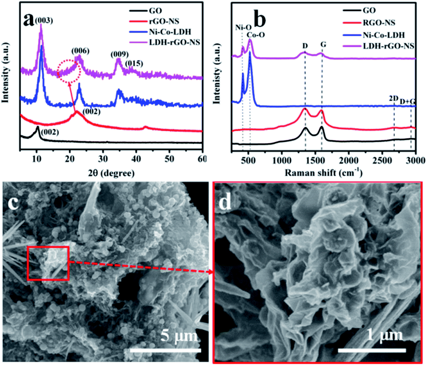 | ||
| Fig. 2 (a) XRD, (b) Raman spectra of GO, RGO-NS, and LDH-rGO-NS, and (c and d) FE-SEM images of the LDH-rGO-NS. | ||
Further, the GO, rGO-NS, Ni–Co-LDH, and LDH-rGO-NS samples are characterized by Raman spectroscopy. These Raman spectra are displayed in Fig. 2b. In the GO sample, four Raman peaks are observed at 1354, 1594, 2677, and 2922 cm−1 designated as D, G, 2D, and D + G, respectively. The D and G peaks are related to the in-plane vibration of sp2 carbon atoms and defects in the GO sample, respectively.22 The D peak is downshifted to 1337 and 1332 cm−1 for rGO-NS and LDH-rGO-NS, respectively. The downshifting of the D peak may have occurred because of N doping and S doping.23,24 The peak positions of G, 2D, and D + G were unaffected for rGO-NS. In the LDH-rGO-NS sample, the peaks corresponding to 2D and D + G bands were disappeared, while peaks associated with D and G bands are present with lower intensity. The Raman spectrum of Ni–Co-LDH shows two main peaks at 417 and 528 cm−1 designated to the vibrational mode of Ni–O, and Co–O, respectively.20,25 Therefore, these two peaks also appeared in the sample in the LDH-rGO-NS sample. LDH-rGO-NS not only reveal the peaks of Ni–Co-LDH but also retain D and G bands of rGO-NS. This result revealed the presence of Ni–Co-LDH and rGO-NS in LDH-rGO-NS sample.
The obtained intensity ratio of the D and G peaks (ID/IG) for GO, rGO-NS, and LDH-rGO-NS are found to be 0.96, 1.13, and 1.11, corresponding to a reduction of GO and an increase in disorder of the graphene. The increase in the ID/IG value suggests the creation of compact sp2 graphitic domains with the reduction of GO.21,26
The FE-SEM images of GO, rGO-NS, and Ni–Co-LDH are displayed in Fig. S1.† The nano-sheet-like structure is obtained for the Ni–Co-LDH. However, the FE-SEM images of the LDH-rGO-NS are displayed in Fig. 2(c and d). The Ni–Co-LDH structures are enfolded well by wrinkled rGO-NS (Fig. 2c). The rGO-NS are doped and reduced during the heating of the mixture solution with the thiourea. The Ni–Co-LDH is positively charged, while the rGO-NS is negatively charged and the Ni–Co-LDH is consequently well wrapped with rGO-NS in the synthesized LDH-rGO-NS. Thus, during the stirring process of the mixture solution of RGO-NS and Ni–Co-LDH, the Ni–Co-LDHs are properly wrapped off with the rGO-NS because of electrostatic interaction between them (Fig. 2d). Thus, RGO-NS wrapped Ni–Co-LDH offers decent flexibility to bear the volume expansion of the Ni–Co-LDH throughout the charge–discharge cycling. The doping of elements and elemental dispersal in Ni–Co-LDH is inspected by the EDS mapping was conducted as shown in Fig. 3(a–f). The present elements are C, Ni, Co, O, S, and N. These elements are homogeneously distributed. Moreover, the TEM image of LDH-rGO-NS confirms a proper wrapping of Ni–Co-LDH with the graphene (Fig. 4a). The rGO-NS have 4–5 layers, which wrap well the Ni–Co-LDH. Furthermore, the HRTEM characterization was used to study the crystallinity of the LDH-rGO-NS. The lattice fringes with d-spacing of ca. 3.93, 2.60, and 2.34 Å are observed to correspond to the (006), (009), and (015) planes, respectively (Fig. 4b). These planes are also observed in the XRD pattern.27 Furthermore, the specific surface area of the Ni–Co-LDH and LDH-rGO-NS is determined by the Brunauer–Emmett–Teller (BET) technique. The obtained BET surface areas are 95.4, 27.5, and 131 cm2 g−1 for rGO-NS, Ni–Co-LDH, and LDH-rGO-NS, respectively (Fig. S2†). This result revealed that after insertion of rGO-NS, the BET surface area is enhanced greatly, which is advantageous for the electrode.
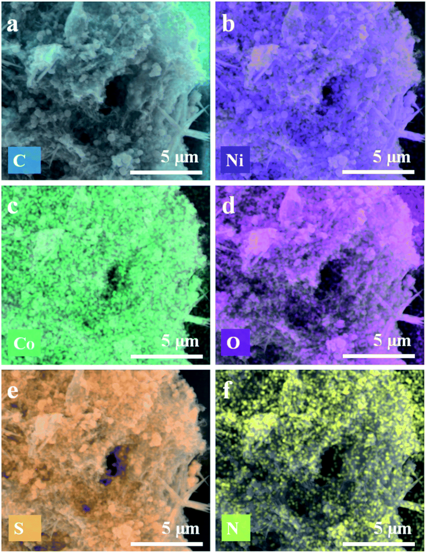 | ||
| Fig. 3 EDS mapping of LDH-rGO-NS for (a) C, (b) Ni, (c) Co, (d) O, (e) S, and (f) N. | ||
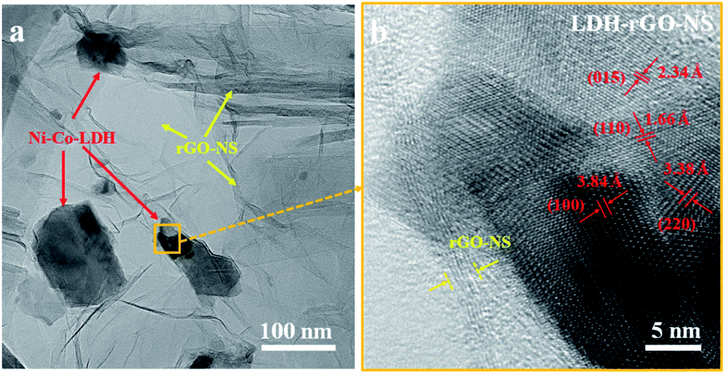 | ||
| Fig. 4 (a) TEM, and (b) HRTEM images of LDH-rGO-NS. | ||
4.2. Elemental analysis
The elemental composition was also analyzed using the XPS characterization technique. The XPS survey spectra are illustrated in Fig. S3.† It approves the existence of the C, Ni, Co, O, S, and N elements in the LDH-rGO-NS.28 The XPS signature of C, Ni, Co, S, and N peaks obtained by the detailed scan are displayed in Fig. 5(a–e). The Gaussian–Lorentzian function is employed to fit XPS data. However, the Shirley technique is employed for background rectification.29 The XPS C 1s spectra are deconvoluted into five main components as displayed in Fig. 5a. The deconvoluted peaks obtained at 282.42, 284.41, 285.60, 287.82, and 291.11 eV are ascribed to C-M (M = Ni or Co), C–C/C![[double bond, length as m-dash]](https://www.rsc.org/images/entities/char_e001.gif) C, CN/C–O/C–S, C–N/CO, and O–CO, respectively.24,30–32 The obtained corresponding percentage of C-bonding is 13.20%, 9.35%, 6.99%, 44.26%, and 26.20%. The presence of C–N & C–S bonds confirm the N and S doping in the graphene. The existence of C–Ni & C–Co indicates dealing amongst Ni–Co-LDH and rGO-NS.
C, CN/C–O/C–S, C–N/CO, and O–CO, respectively.24,30–32 The obtained corresponding percentage of C-bonding is 13.20%, 9.35%, 6.99%, 44.26%, and 26.20%. The presence of C–N & C–S bonds confirm the N and S doping in the graphene. The existence of C–Ni & C–Co indicates dealing amongst Ni–Co-LDH and rGO-NS.
 | ||
| Fig. 5 XPS spectra of (a) C 1s, (b) Ni 2p, (c) Co 2p, (d) S 2p, and (e) N 1s scan for LDH-rGO-NS. | ||
The XPS scan of the Ni 2p spectrum is displayed in Fig. 5b. There are two main peaks at 856.19 and 873.64 eV associated with Ni2+ characteristics of Ni 2p3/2 and Ni 2p1/2, respectively.33 The space between these two peaks (ΔE) is ∼17.45 eV, which is approximately the same as the standard spacing between Ni 2p3/2 and Ni 2p1/2 of Ni2+ state in NiO,34 thus confirming the dominating valence state of Ni2+ in Ni–Co-LDH. Moreover, two additional peaks associated with shakeup satellites (denoted by Sat.) of Ni 2p3/2 and Ni 2p1/2 are obtained at 862.2 and 879.59 eV, respectively. However, four peaks are obtained for Co 2p associated with Co 2p3/2 and Co 2p1/2. The 2p3/2 peak is composed of two peaks corresponding to Co3+ and Co2+ located at 780.46 and 783.41 eV, respectively. Similarly, the 2p1/2 peak is also deconvoluted into two peaks analogous to Co3+ and Co2+ situated at 799.23 and 800.89 eV, respectively (Fig. 5c).35 Moreover, two additional peaks associated with shakeup satellites of Co 2p3/2 and Co 2p1/2 are obtained at 785.62 and 803.15 eV, respectively. A low-intensity peak corresponding to Co 2p3/2 is demonstrating the existence of both Co3+ and Co2+ in LDH-rGO-NS.8,36,37 However, the spacing between Co 2p3/2 and Co 2p1/2 is 16.42 eV indicating that the dominant valence state is Co2+, which is slightly larger than the earlier stated values of 15.90 eV (ref. 15) and 15.70 eV.7
The deconvoluted XPS S 2p spectra are displayed in Fig. 5d. Two peaks are corresponding to S 2p3/2 and S 2p1/2 located at 161.71 and 163.49 eV, respectively. The spacing between these two peaks is 1.78 eV, which is quite larger than the pristine S.34 Moreover, two peaks associated with oxidized S of lower intensity are observed at 166.9 and 170.2 eV.
Fig. 5e shows a detailed XPS N 1s peak. The N 1s spectrum is deconvoluted into four peaks positioned at 398.01, 399.72, 401.89, and 403.21 eV, which correspond to pyridinic-N, pyrrolic-N, graphitic-N, and oxidized-N, respectively.16,18 The obtained corresponding percentage of N moieties is 14.48%, 20.79%, 40.25%, and 24.48%, respectively. It can be seen that graphitic N has a maximum fraction, which can act as a strong electron-donating group to the aromatic π-system.18,38
4.3. Electrochemical properties
The electrochemical performance of the electrode materials is assessed using EIS, CV, and GCD. Fig. 6a shows the CV curves of LDG-rGO-NS at ν value of 2, 5, 20, and 50 mV s−1. Besides, Fig. S4† displayed the CV curves for higher san rates (100 and 200 mV s−1). The CV curves at various ν values offer a couple of strong redox peaks because of the pseudo-capacitive behavior of M(OH)2/MOOH.39 These peaks are arising owing to the alteration of Ni2+/Ni3+ and Co2+/Co3+ ions adsorbed onto the exterior of Ni–Co-LDH throughout the redox reaction.16 The expected reactions involved to arise the redox peaks would be given by eqn (1) and (2)40,41| Ni(OH)2 + OH− → NiOOH + H2O + e− | (1) |
| Co(OH)2 + OH− → CoOOH + H2O + e− | (2) |
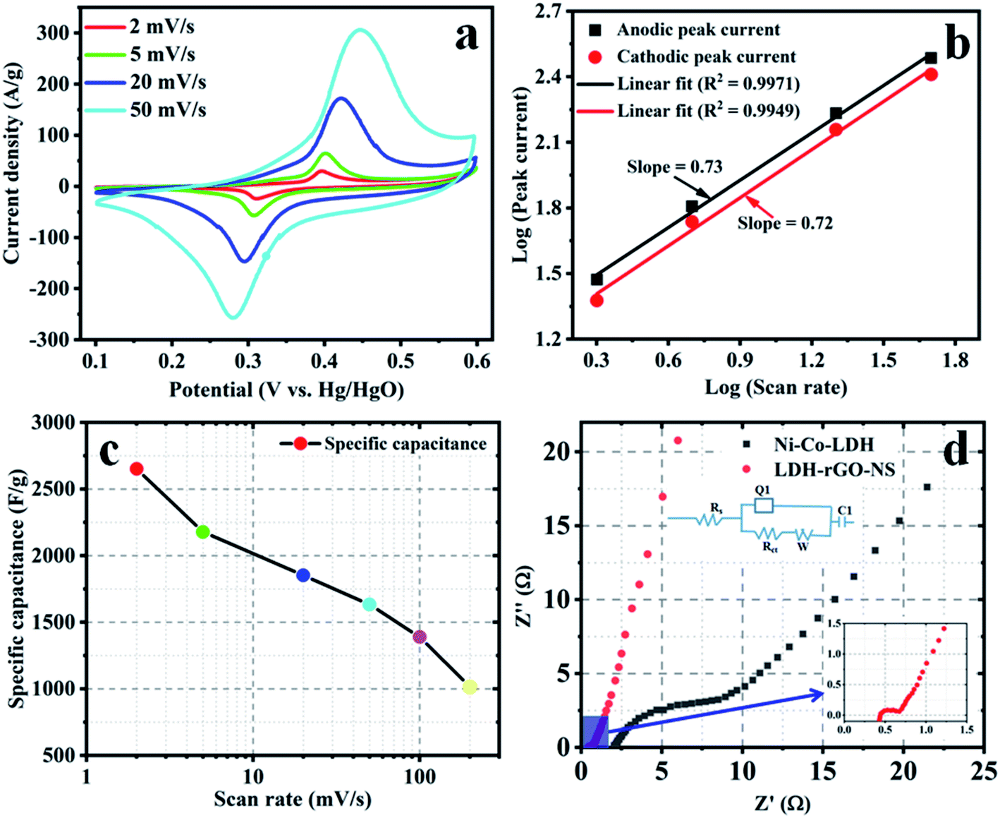 | ||
| Fig. 6 Electrochemical characterization (a) cyclic-voltammetry at various sweep rates, (b) log(peak current) vs. log(sweep rate), (c) specific capacity as a function of sweep rate, and (d) EIS of LDH-rGO-NS electrode. | ||
The effectiveness of the above charge storing mechanisms is evaluated by determining the b-value of the relation (3)42
| ip = aυb | (3) |
It can be noted that the spacing between anodic and cathodic peaks increases with the rise in ν value. However, the appearance of the curves is unchanged. The specific capacitances (Cs) at various ν is determined by the relation (4)8
 | (4) |
 is the charge, which is determined by integration of the CV curve, m = active mass of the electrode (g), and (V2 − V1) = potential window (V).
The obtained values of Cs are 2651, 2178, 1853, 1633, 1388, and 1016 F g−1 at ν = 2, 5, 20, 50, 100, and 200 mV s−1, respectively. The Cs value at a ν = 20 mV s−1 is ∼70% of the Cs value obtained at 2 mV s−1 (Fig. 6c). However, the capacity of Ni–Co-LDH is obtained as 1226 F g−1, which is quite lower than the LDH-rGO-NS (Fig. S5†). The stability of the electrode materials was tested using a long-cycled CV measurement. The CV of 1st, 1000th and 2000th cycles at a ν = 100 mV s−1 are shown in Fig. S6.† The obtained results revealed that the retention rate is ∼71% at the ν = 100 mV s−1 after 2000 cycles.
The ion/charge transportation was investigated using EIS measurement. The Nyquist plots of the Ni–Co-LDH and LDH-rGO-NS electrodes are displayed in Fig. 6d (inset shows the equivalent circuit), which revealed the value of series resistance (Rs) and charge transfer resistance (Rct). Usually, the Nyquist plot consists of two different fragments: a semicircle is obtained in the mid-high frequency section, while a lined shape is formed in the low-frequency region. The EIS data is used to fit using an equivalent circuit (inset of Fig. 6d).37 The initial point of the semicircle gives the value of Rs, whereas the diameter provides the value of Rct. Rs is indicative of the resistivity of the electrode materials, Rct is associated with faradaic reactions and double-layer capacitance.46 The constant phase element (Q1) is responsible for the double-layer capacitance. However, W and C1 are the Warburg resistance and limiting capacitance. W is due to ion diffusion and transportation in the electrolyte. The obtained values of Rs and Rct for the LDH-rGO-NS electrode are found to be 0.43 and 0.24 Ω, respectively. However, the obtained Rs and Rct values are 2.15 and 7.83 Ω, respectively. The Rs value of LDH-rGO-NS is slightly higher than the Ni–Co-LDH composite with N-doped rGO (LDH-rGO-N) (0.31 Ω) obtained by Wang et al.16 but quite lower than the composite Ni–Co-LDH and rGO (Ni–Co-LDH/rGO) (1.099 Ω) obtained by Le et al.15 This confirms that the LDH-rGO-NS offers good conductivity (inset of Fig. 6d). Moreover, the obtained value of Rct of LDH-rGO-NS is 0.24 Ω, which is similar to LDH/rGO (0.22 Ω) showed by Le et al.15
GCD characterization is used for an additional assessment of the electrochemical performance of the LDH-rGO-NS electrode. Fig. 7a shows the discharge characteristics of the LDH-rGO-NS electrode at various current densities of 5, 10, 20, and 50 A g−1. However, the discharge characteristics of the LDH-rGO electrode are shown in Fig. S7† for comparison. The discharge curves were used to determine the specific discharge capacitance (Cds) at various discharge current (I) using relation (5)15
 | (5) |
 | ||
| Fig. 7 Electrochemical characterization (a) galvanometric discharge curves at various discharge current densities (5, 10, 20, 50 A g−1) and (b) specific capacity as a function of discharge current density of LDH-rGO-NS electrode. | ||
The obtained Cds values of LDH-rGO-NS electrode are 2193, 1806, 1556, and 1290 F g−1 at the discharge current density of 5, 10, 20, and 50 A g−1, respectively. However, the Cds values of LDH-rGO obtained at 5, 10, 20, and 50 A g−1 are 2050, 1646, 1352, and 1060 F g−1, respectively. The dependency of the Cds on discharge current density can be seen in Fig. 7b. The values of Cds of LDH-rGO-NS is quite higher than the values LDH-rGO electrode. Furthermore, the obtained discharge capacitance of values of the LDH-rGO-NS electrode is compared in Table 1. The Cds value of LDH-rGO-NS is larger than the values achieved in earlier reports associated with LDH/rGO-based materials.15,37,47–51 In LDH-rGO-NS, the electrochemical performance is enhanced due to an excellent ion/charge transfer rate because of N and S co-doping.
| Electrode materials | Specific discharge capacitance (F g−1) | Discharge current density (A g−1) | Electrolyte (KOH) concentration | Loading mass (mg cm−2) | Ref. |
|---|---|---|---|---|---|
| a rGO-N = N-doped rGO.b Act-rGO = activated rGO. | |||||
| Ni–Co-LDH/rGO | 2004, 2130 | 5.0, 2.0 | 3 M | 2.1 | 15 |
| Ni–Co-LDH/rGO-Na | 1720 | 3.0 | 6 M | 1.0 | 16 |
| Ni–Co-LDH/graphene sheet | 1980.7 | 1.0 | 6 M | — | 48 |
| Ni–Co-LDH/rGO | 1911 | 2.0 | 3 M | 1.5 | 37 |
| Ni–Co-LDH/rGO | 1691 | 0.5 | 6 M | 3.0 | 49 |
| Ni–Al-LDH/act-rGOb | 1173 | 1.0 | 6 M | — | 50 |
| Co–Al-LDH/rGO | 1962 | 1.0 | 6 M | — | 51 |
| LDH-rGO-NS | 2193 | 5.0 | 6 M | 1.0 | This work |
The energy density (E) and power density (P) are determined using eqn (6) and (7), respectively.8
 | (6) |
 | (7) |
GCD curves of the LDH-rGO-NS//AC supercapacitors at various are illustrated in Fig. 8a. The discharge curves were used to determine the values of E and P. The obtained energy density and power density are shown in the Ragone plot (Fig. 8b). The obtained energy density is 38.8 W h kg−1 at a power density of 746.5 W kg−1. Even at a power density of 3827.9 W kg−1, the obtained energy density is 27.8 W h kg−1.
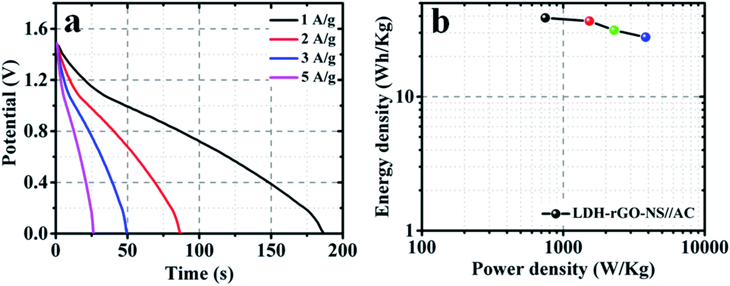 | ||
| Fig. 8 Electrochemical characterization (a) galvanometric discharge curves at various discharge current densities and (b) Ragone plot of the LDH-rGO-NS//AC asymmetric supercapacitors. | ||
5. Conclusions
The single-step hydrothermal process was used to synthesize LDG-rGO-NS. Various techniques were used to characterize the LDH-rGO-NS sample. The XRD and Raman studies of LDH-rGO-NS revealed the presence of both Ni–Co-LDH and graphene. The FE-SEM results confirmed that the shape of the Ni–Co-LDH was spherical. The Ni–Co-LDH structures are swathed well by wrinkled rGO-NS. The XPS C 1s spectra established the existence of N and S doping in the rGO. The superior values of the anodic (0.73) and cathodic (0.72) b-value were accomplished. Moreover, the EIS result showed that the LDH-rGO-NS electrode proposes a good charge transfer resistance of 0.24 Ω. The electrochemical performance was enhanced due to an excellent ion/charge conductance because of N and S co-doping. The existence of C–Ni & C–Co peaks confirmed that an interaction occurs between Ni–Co-LDH and rGO-NS. The obtained specific capacities were 2651, 2178, 1853, 1633, 1388, and 1016 F g−1 at ν = 2, 5, 20, 50, 100, and 200 mV s−1, respectively. The retention rate obtained after 2000 cycles was ∼71% at ν = 100 mV s−1. Besides, the specific capacity values obtained from GCD are 2193, 1806, 1556, and 1290 F g−1 at the discharge current density of 5, 10, 20, and 50 A g−1, respectively. The achieved energy density of the LDH-rGO-NS//AC asymmetric supercapacitors was 38.8 W h kg−1 at the power density of 746.5 W kg−1. The LDH-rGO-NS can be a potential candidate as an electrode material for high-performance electrochemical energy storage devices.Ethical statement
This article does not contain any studies with human or animal subjects.Conflicts of interest
The author declares no conflict of interest.Acknowledgements
The author gratefully acknowledges funding (Project No. SR181030) from the Deanship of Research Oversight and Coordination (DROC), King Fahd University of Petroleum & Minerals (KFUPM), Saudi Arabia.References
- F. Wang, Z. Zuo, L. Li, F. He, F. Lu and Y. Li, Adv. Mater., 2019, 31, 1806272 Search PubMed.
- L. Li, Z. Zuo, F. Wang, J. Gao, A. Cao, F. He and Y. Li, Adv. Mater., 2020, 32, 2000140 CrossRef CAS PubMed.
- M. Yu, Z. Wang, Y. Han, Y. Tong, X. Lu and S. Yang, J. Mater. Chem. A, 2016, 4, 4634–4658 RSC.
- A. Muzaffar, M. B. Ahamed, K. Deshmukh and J. Thirumalai, Renewable Sustainable Energy Rev., 2019, 101, 123–145 CrossRef CAS.
- T. Li, R. Li and H. Luo, J. Mater. Chem. A, 2016, 4, 18922–18930 RSC.
- J. Wu, W.-W. Liu, Y.-X. Wu, T.-C. Wei, D. Geng, J. Mei, H. Liu, W.-M. Lau and L.-M. Liu, Electrochim. Acta, 2016, 203, 21–29 CrossRef CAS.
- L. Sun, L. Wang, C. Tian, T. Tan, Y. Xie, K. Shi, M. Li and H. Fu, RSC Adv., 2012, 2, 4498 RSC.
- B. Zhao, D. Chen, X. Xiong, B. Song, R. Hu, Q. Zhang, B. H. Rainwater, G. H. Waller, D. Zhen, Y. Ding, Y. Chen, C. Qu, D. Dang, C.-P. Wong and M. Liu, Energy Storage Mater., 2017, 7, 32–39 CrossRef.
- J. H. Lee, S. H. Kwon, S. Kwon, M. Cho, K. H. Kim, T. H. Han and S. G. Lee, Nanomaterials, 2019, 9, 268 CrossRef CAS PubMed.
- X. Li, D. Du, Y. Zhang, W. Xing, Q. Xue and Z. Yan, J. Mater. Chem. A, 2017, 5, 15460–15485 RSC.
- X. Sun, G. Wang, H. Sun, F. Lu, M. Yu and J. Lian, J. Power Sources, 2013, 238, 150–156 CrossRef CAS.
- J. Yang, C. Yu, X. Fan and J. Qiu, Adv. Energy Mater., 2014, 4, 1400761 CrossRef.
- T. Wang, L. X. Wang, D. L. Wu, W. Xia and D. Z. Jia, Sci. Rep., 2015, 5, 9591 CrossRef CAS PubMed.
- Z. S. Wu, A. Winter, L. Chen, Y. Sun, A. Turchanin, X. Feng and K. Mullen, Adv. Mater., 2012, 24, 5130–5135 CrossRef CAS PubMed.
- K. Le, Z. Wang, F. Wang, Q. Wang, Q. Shao, V. Murugadoss, S. Wu, W. Liu, J. Liu, Q. Gao and Z. Guo, Dalton Trans., 2019, 48, 5193–5202 RSC.
- W. Wang, N. Zhang, Z. Ye, Z. Hong and M. Zhi, Inorg. Chem. Front., 2019, 6, 407–416 RSC.
- J. P. Paraknowitsch and A. Thomas, Energy Environ. Sci., 2013, 6, 2839 RSC.
- F. Khan, S.-H. Baek and J. H. Kim, Carbon, 2016, 100, 608–616 CrossRef CAS.
- F. Khan and J. H. Kim, J. Ind. Eng. Chem., 2018, 68, 129–139 CrossRef CAS.
- H. Xu, J. Wu, J. Liu, Y. Chen and X. Fan, J. Mater. Sci.: Mater. Electron., 2018, 29, 17234–17244 CrossRef CAS.
- S. P. Lonkar, J. M. Raquez and P. Dubois, Nano-Micro Lett., 2015, 7, 332–340 CrossRef PubMed.
- A. Kaniyoor and S. Ramaprabhu, AIP Adv., 2012, 2, 032183 CrossRef.
- R. Lv, Q. Li, A. R. Botello-Mendez, T. Hayashi, B. Wang, A. Berkdemir, Q. Hao, A. L. Elias, R. Cruz-Silva, H. R. Gutierrez, Y. A. Kim, H. Muramatsu, J. Zhu, M. Endo, H. Terrones, J. C. Charlier, M. Pan and M. Terrones, Sci. Rep., 2012, 2, 586 CrossRef PubMed.
- A. Das, S. Pisana, B. Chakraborty, S. Piscanec, S. K. Saha, U. V. Waghmare, K. S. Novoselov, H. R. Krishnamurthy, A. K. Geim, A. C. Ferrari and A. K. Sood, Nat. Nanotechnol., 2008, 3, 210–215 CrossRef CAS PubMed.
- J. Memon, J. Sun, D. Meng, W. Ouyang, M. A. Memon, Y. Huang, S. Yan and J. Geng, J. Mater. Chem. A, 2014, 2, 5060 RSC.
- R. Xie, G. Fan, Q. Ma, L. Yang and F. Li, J. Mater. Chem. A, 2014, 2, 7880 RSC.
- L. Shi, Y. Chen, R. He, X. Chen and H. Song, Phys. Chem. Chem. Phys., 2018, 20, 16437–16443 RSC.
- L. Jiang, R. Zou, W. Li, J. Sun, X. Hu, Y. Xue, G. He and J. Hu, J. Mater. Chem. A, 2013, 1, 478–481 RSC.
- D. A. Shirley, Phys. Rev. B, 1972, 5, 4709 CrossRef.
- J. Zhou, J. Li, K. Liu, L. Lan, H. Song and X. Chen, J. Mater. Chem. A, 2014, 2, 20706–20713 RSC.
- S. Bian, C. Shen, Y. Qian, J. Liu, F. Xi and X. Dong, Sens. Actuators, B, 2017, 242, 231–237 CrossRef CAS.
- F. Khan, M. Oh and J. H. Kim, Chem. Eng. J., 2019, 369, 1024–1033 CrossRef CAS.
- J. Zhao, J. Chen, S. Xu, M. Shao, Q. Zhang, F. Wei, J. Ma, M. Wei, D. G. Evans and X. Duan, Adv. Funct. Mater., 2014, 24, 2938–2946 CrossRef CAS.
- J. Moulder, W. Stickle, P. Sobol and K. Bomben, There is no corresponding record for this reference, Google Scholar, 1992, pp. 52–53 Search PubMed.
- C. Shang, S. Dong, S. Wang, D. Xiao, P. Han, X. Wang, L. Gu and G. Cui, ACS Nano, 2013, 7, 5430–5436 CrossRef CAS PubMed.
- H. Chen, L. Hu, M. Chen, Y. Yan and L. Wu, Adv. Funct. Mater., 2014, 24, 934–942 CrossRef CAS.
- X. Cai, X. Shen, L. Ma, Z. Ji, C. Xu and A. Yuan, Chem. Eng. J., 2015, 268, 251–259 CrossRef CAS.
- S. Jalili and R. Vaziri, Mol. Phys., 2011, 109, 687–694 CrossRef CAS.
- T. Wang, S. Zhang, X. Yan, M. Lyu, L. Wang, J. Bell and H. Wang, ACS Appl. Mater. Interfaces, 2017, 9, 15510–15524 CrossRef CAS PubMed.
- X. Wang, C. Yan, A. Sumboja, J. Yan and P. S. Lee, Adv. Energy Mater., 2014, 4, 1301240 CrossRef.
- J. Li, M. Yang, J. Wei and Z. Zhou, Nanoscale, 2012, 4, 4498–4503 RSC.
- Y. Gogotsi and R. M. Penner, ACS Nano, 2018, 12, 2081–2083 CrossRef CAS PubMed.
- C. Hou, Z. Tai, L. Zhao, Y. Zhai, Y. Hou, Y. Fan, F. Dang, J. Wang and H. Liu, J. Mater. Chem. A, 2018, 6, 9723–9736 RSC.
- P. Simon, Y. Gogotsi and B. Dunn, Science, 2014, 343, 1210–1211 CrossRef CAS PubMed.
- T. Brousse, D. Bélanger and J. W. Long, J. Electrochem. Soc., 2015, 162, A5185–A5189 CrossRef CAS.
- J. W. Lee, J. M. Ko and J.-D. Kim, Electrochim. Acta, 2012, 85, 459–466 CrossRef CAS.
- Y. Cao, G. Li and X. Li, Chem. Eng. J., 2016, 292, 207–223 CrossRef CAS.
- T. Yan, R. Li and Z. Li, Mater. Res. Bull., 2014, 51, 97–104 CrossRef CAS.
- H. Ma, J. He, D. B. Xiong, J. Wu, Q. Li, V. Dravid and Y. Zhao, ACS Appl. Mater. Interfaces, 2016, 8, 1992–2000 CrossRef CAS PubMed.
- N. Yulian, L. Ruiyi, L. Zaijun, F. Yinjun and L. Junkang, Electrochim. Acta, 2013, 94, 360–366 CrossRef.
- L. Zhang, K. N. Hui, K. S. Hui and H. Lee, Electrochim. Acta, 2015, 186, 522–529 CrossRef CAS.
Footnote |
| † Electronic supplementary information (ESI) available. See DOI: 10.1039/d1ra07235h |
| This journal is © The Royal Society of Chemistry 2021 |