 Open Access Article
Aggregation of retained helium and hydrogen in titanium beryllide Be12Ti: a first-principles study
Yinlong Wang†
abd,
Canglong Wang† *bcd,
Zhaocang Mengbcd,
Jitao Liubcd,
Yuhong Li*a and
Lei Yangbcd
aSchool of Nuclear Science and Technology, Lanzhou University, Lanzhou, 730000, China. E-mail: liyuhong@lzu.edu.cn
bInstitute of Modern Physics, Chinese Academy of Sciences, Lanzhou, 730000, China. E-mail: clwang@impcas.ac.cn
cSchool of Nuclear Science and Technology, University of Chinese Academy of Sciences, Beijing, 100049, China
dAdvanced Energy Science and Technology Guangdong Laboratory, Huizhou, 516000, China
First published on 27th October 2021
Abstract
Titanium beryllide, Be12Ti, has been proposed as a prospective neutron multiplier in fusion reactors. First-principles calculations have been performed to investigate the nucleation mechanism of a He bubble in bulk Be12Ti. Meanwhile, the influence of the presence of H atoms on the nucleation of the He bubble, i.e., the synergistic effect of He and H atoms, has also been investigated. It has been found that the He bubble will initially nucleate around a monovacancy (VBe2). When more He atoms have been implanted, two newly induced vacancies (VBe1 and VBe3) could be successively observed. The nucleation of the He bubble will occur around the divacancy of VBe2VBe1 and the trivacancy of VBe2VBe1VBe3. Dumbbell structures in the He bubble evolve with the number of implanted He atoms and finally disappear. The presence of H atoms will significantly influence the nucleation of the He bubble. It is interesting that some tetrahedral and octahedral structures have also been observed. The maximal number of H atoms trapped by a He bubble has been obtained. These phenomena could be further explained by the continuous shrinking of the isosurface of charge density. The present results provide a microscopic physical foundation to understand the mechanism of He and H atoms retention in neutron multiplier materials. This investigation could be helpful for the design and fabrication of more promising beryllides which could withstand a severe external environment.
1 Introduction
As promising neutron multiplier materials, beryllium (Be) and beryllium intermetallic compounds (e.g., Be12Ti) have potential applications in accelerators of boron neutron capture therapy (BNCT)1 and solid breeding blankets in fusion demonstration (DEMO) reactors.2,3 However, the radiogenic gas tritium (hydrogen isotope, T) and helium (He) with different concentrations simultaneously produced by neutron irradiations will inevitably accumulate in Be4 and beryllides,5 which could induce structural damage6 and degradation of material properties.7,8 In particular, the retention of radioactive tritium could bring difficulties in the disposal of Be-based wastes. The retention and release of tritium and helium in neutron multiplier materials have been one of the key issues for the design and safety assessment of fusion reactors.6 Beryllides, such as Be12Ti, are superior to pure Be due to lower irradiation swelling9 and smaller hydrogen (H) retention.10Under irradiation, various defects, such as vacancies, could be produced. H or He atoms could be easily trapped by vacancies to form H/He–vacancy (abbreviated as H/He–V) complexes11,12 owing to the attraction of vacancies to H or He atoms. With more H or He atoms binding to H/He–V complexes, small gas bubbles begin to form, and finally grow large with the coalescence of small bubbles.12 The distribution, density and mean size of the He bubbles are dependent on the irradiation temperature, the structure of the irradiated material itself and the energy and concentration of the implanted He ions.13,14 The synergistic effect between He and H atoms is an interesting topic of research in gas retention and release. It has been reported15 that, in Be co-deposits, a lower He concentration could promote the retention of deuterium (hydrogen isotope, D) while a higher He concentration could reduce the retention of D. He bubbles could grow larger under subsequent H irradiations.12 The evidence for the co-existence of T and He in common bubbles has been found in research on the desorption of T and He atoms in Be.16,17 During the evolution of mixed gas bubbles, which contain both H and He atoms, H atoms tend to be distributed on the surface of the He bubbles.18,19 However, to our knowledge, the phenomena of mixed bubbles containing both H and He atoms are rarely reported in titanium beryllide Be12Ti.
First-principles calculations could provide a feasible way to better understand the physical micromechanism of various irradiation effects.20–22 In particular, the early stage of nucleation of He or H bubbles has been widely simulated by first-principles calculations.23–25 For pure Be, the calculated formation energy of a monovacancy is consistent with the data deduced from experiment.26 Divacancies in Be are energetically unstable,27 but He atoms could stabilize the divacancies when they bind to divacancy clusters, which are in specific orientations.28 A monovacancy could trap up to five H atoms or twelve He atoms in pure Be, and the formation of a H2 molecule is impossible.29 The research30 has shown that the diffusion of a single H atom in Be12Ti with a vacancy becomes relatively difficult due to a higher barrier energy compared with that in perfect Be12Ti. This indicates that vacancies could act as traps for H atoms. It has been further investigated31 that three different types of Be vacancies could all trap four H atoms and a Ti vacancy could trap ten H atoms.
However, few works have been focused on the investigation of the micromechanism of He bubble nucleation, especially the influence of the presence of H atoms on the He bubbles, i.e., the synergistic effect of H and He atoms in Be12Ti. The purpose of this work is to model the nucleation of He bubbles, primarily by investigating the ability of a monovacancy to trap multiple He atoms in Be12Ti. Besides, the mixed bubbles containing both H and He atoms are also simulated further to explore the synergistic effect of H and He atoms, which is significant in understanding the micromechanism behind the retention of He and H atoms in Be12Ti.
2 Computational methodology
In this work, all the first-principles calculations are carried out within the density functional theory (DFT) framework as implemented in the Vienna Ab initio Simulation Package (VASP).32,33 The ion–electron interaction is described using the projector augmented-wave (PAW) method.34 The generalized gradient approximation (GGA) developed by Perdew and Wang35 has been employed to calculate the exchange–correlation energy. All the defect calculations are performed based on a tetragonal supercell containing 208 atoms. The plane-wave cutoff energy is set as 500 eV, and a k-point mesh of 2 × 2 × 4 is employed for Brillouin-zone integration according to the Monkhorst–Pack scheme,36 which has been well tested. The shape and volume of perfect bulk Be12Ti have been fully relaxed and the dimensions are kept fixed for all the defect calculations. For the geometry optimization, all atoms are relaxed until the total energy difference and forces on each atom are less than 10−6 eV and 0.001 eV Å−1, respectively.The solution energy for a single H or He atom at an interstitial site in Be12Ti has the following formalism:
 | (1) |
The formation energy of one vacancy in Be12Ti has the following formalism:
| Efor = E(V) − E(bulk) + μX | (2) |
The binding energy between one vacancy and a single H or He atom has the following formalism:
| Ebind = E(H/He,V) − E(H/He) − E(V) + E(bulk) | (3) |
The solution energy for nHe and/or mH atoms (n ≥ 1, m ≥ 0) in Be12Ti with one vacancy is calculated by the following formalism:
 | (4) |
To interpret the degree of lattice deformation, the deformation energy induced by the incorporation of nHe and/or mH atoms into the system with one vacancy has also been calculated by the following formalism:
| Edef = E[(Hen–V–Hm)–nHe–mH] − E(V) | (5) |
The trapping energy has been defined as the energy required to move an interstitial He atom into one vacancy or an interstitial H atom into a Hen–V complex. For He atoms trapped by one vacancy, the trapping energy has the following formalism:
| Etrap = E(Hen–V) E(Hen−1–V) − E(HeI) + E(bulk) | (6) |
For H atoms trapped by a Hen–V complex, the trapping energy has the following formalism:
| Etrap = E(Hen–V–Hm) − E(Hen–V–Hm−1) − E(HI) + E(bulk) | (7) |
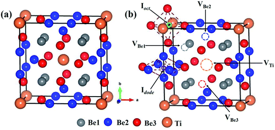
The bulk Be12Ti has tetragonal symmetry in the space group of I4/mmm.38,39 Ti atoms occupy the Wyckoff position of the 2a lattice site (0, 0, 0), and three symmetrically different Be atoms, which are labeled as Be1, Be2 and Be3, occupy the Wyckoff positions of 8f (0.25, 0.25, 0.25), 8i (0.361, 0, 0) and 8j (0.277, 0.5, 0), respectively. The structure of the unit cell for Be12Ti is shown in Fig. 1(a), where the orange spheres represent Ti atoms and the grey, blue and red spheres represent Be1, Be2 and Be3 atoms, respectively. The obtained lattice constants are a = b = 7.328 Å, and c = 4.145 Å, which are in good agreement with previous experimental38,40 and theoretical calculation results.31,41,42
3 Results and discussion
3.1 Stability of individual H and He atoms in Be12Ti
The stability of individual H and He atoms in perfect Be12Ti has been investigated. There are seven energetically stable interstitial sites for single H and He atoms.30 For a single H atom, it has the lowest solution energy of 0.509 eV at an octahedral interstitial site (Ioct), as shown in Fig. 1(b). For an individual He atom, it preferentially occupies a dodecahedral interstitial site (Idode) (Fig. 1(b)) with the lowest solution energy of 4.028 eV. These results are consistent with the previous results.30There are four types of vacancies: VBe1 (Be1 vacancy), VBe2 (Be2 vacancy), VBe3 (Be3 vacancy) and VTi (Ti vacancy), as shown in Fig. 1(b). The formation energies of these vacancies are summarised in Table 1, together with previous results for comparison. Obviously, the vacancy VBe2 has the lowest formation energy among these vacancies. Therefore, we have only investigated the interactions between the defect of VBe2 and H/He atoms throughout the work. A thorough search has been performed to ascertain the preferential site for both H and He atoms around VBe2.
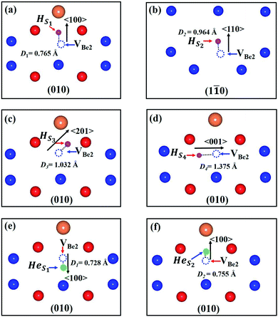
As we can see from Fig. 2, there are four stable sites and two stable sites distributed in the different crystallographic planes for the presence of single H and He atoms, respectively. Meanwhile, the solution energies and binding energies are presented in Table 2. VBe2 exhibits attraction to both H and He atoms. For a single H atom, VBe2 has the strongest attraction to a H atom, with a binding energy of −0.670 eV. H atom and VBe2 are distributed approximately along the direction of 〈201〉 in the plane of (010), and the distance between the H atom and the center of the Be2 vacancy is 1.032 Å, as shown in Fig. 2(c). For a single He atom, the configuration shown in Fig. 2(e) corresponds to the most stable state, with a binding energy of −2.130 eV and a distance of 0.728 Å. A similar tendency could also be observed for the solution energies.
| Configuration | Distance (Å) | Esol (eV) | Ebind (eV) |
|---|---|---|---|
| HS1 | 0.765 | 0.074 | −0.435 |
| HS2 | 0.964 | −0.079 | −0.588 |
| HS3 | 1.032 | −0.160 | −0.670 |
| HS4 | 1.375 | 0.298 | −0.212 |
| HeS1 | 0.728 | 1.898 | −2.130 |
| HeS2 | 0.755 | 2.236 | −1.792 |
3.2 Nucleation mechanism of a He bubble in the most stable monovacancy
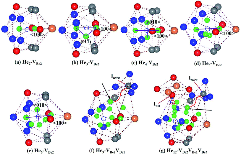
It has been revealed that monovacancy VBe2 is preferentially formed in bulk Be12Ti. It is important to get insight into the nucleation mechanism of a He bubble in VBe2. Thus, the nucleation process of Hen–VBe2 complexes (n is the number of He atoms, n ≥ 1) has been investigated in the following paragraph.Considering the low He concentration, He atoms are placed near to VBe2 one by one, that is, the “sequential way”43 has been adopted to simulate the nucleation of the He bubble; this has also been applied in many investigations related to the nucleation of He or H bubbles.44,45 The solution energies, trapping energies and deformation energies are summarised in Table 3. For the simplest He–VBe2 complex, the most stable configuration has been obtained, as shown in Fig. 2(e). When an extra He atom is trapped by a He–VBe2 complex, the He2–VBe2 complex has the configuration of a dumbbell with a trapping energy of −1.525 eV, which exactly distributes along the direction of 〈100〉, as shown in Fig. 3(a). The distance between two He atoms is 1.611 Å, and VBe2 is located in the middle of the dumbbell. When the third He atom is implanted into the He2–VBe2 complex, the above mentioned dumbbell configuration is also observed, but the distance between the two He atoms increases to 1.976 Å. The distances between the third He atom and the other two He atoms are 1.499 Å and 1.524 Å. Thus, the He3–VBe2 complex has the approximate shape of an isosceles triangle located in the plane of (01![[1 with combining macron]](https://www.rsc.org/images/entities/char_0031_0304.gif) ), which is shown in Fig. 3(b). The trapping energy of the He atoms is −0.713 eV. In the He4–VBe2 complex with a trapping energy of −1.019 eV, as shown in Fig. 3(c), besides the dumbbell distributing along the direction of 〈100〉, another dumbbell configuration is also observed, which distributes along the direction of 〈010〉. In the most stable configuration of the He5–VBe2 complex with a trapping energy of −0.764 eV, the initial dumbbell slightly deviates from its original direction of 〈100〉. Whereas the dumbbell with a direction of 〈010〉 disappears, as shown in Fig. 3(d). In the configuration of the He6–VBe2 complex, there are also two dumbbells: one approximately distributes along the direction of 〈100〉, and the other is along the direction of 〈01
), which is shown in Fig. 3(b). The trapping energy of the He atoms is −0.713 eV. In the He4–VBe2 complex with a trapping energy of −1.019 eV, as shown in Fig. 3(c), besides the dumbbell distributing along the direction of 〈100〉, another dumbbell configuration is also observed, which distributes along the direction of 〈010〉. In the most stable configuration of the He5–VBe2 complex with a trapping energy of −0.764 eV, the initial dumbbell slightly deviates from its original direction of 〈100〉. Whereas the dumbbell with a direction of 〈010〉 disappears, as shown in Fig. 3(d). In the configuration of the He6–VBe2 complex, there are also two dumbbells: one approximately distributes along the direction of 〈100〉, and the other is along the direction of 〈01![[1 with combining macron]](https://www.rsc.org/images/entities/char_0031_0304.gif) 〉, as shown in Fig. 3(e). The trapping energy of the He atoms is −0.851 eV. In the most stable configuration of the He7–VBe2 complex, dumbbells similar to those in the He4–VBe2 complex are also obtained. The trapping energy for the He atoms is −0.908 eV. When one new He atom is added into the He7–VBe2 complex, the two dumbbells deviate from their original directions. The trapping energy of the He atoms is −0.836 eV. The deformation of the lattice becomes more obvious, where some of Be atoms near the He8–VBe2 complex begin to deviate from their lattice sites due to the repulsion of He atoms.
〉, as shown in Fig. 3(e). The trapping energy of the He atoms is −0.851 eV. In the most stable configuration of the He7–VBe2 complex, dumbbells similar to those in the He4–VBe2 complex are also obtained. The trapping energy for the He atoms is −0.908 eV. When one new He atom is added into the He7–VBe2 complex, the two dumbbells deviate from their original directions. The trapping energy of the He atoms is −0.836 eV. The deformation of the lattice becomes more obvious, where some of Be atoms near the He8–VBe2 complex begin to deviate from their lattice sites due to the repulsion of He atoms.
| Configuration | Esol (eV) | Etrap (eV) | Edef (eV) |
|---|---|---|---|
| He1–VBe2 | 1.898 | −2.130 | 0.191 |
| He2–VBe2 | 4.402 | −1.525 | 0.525 |
| He3–VBe2 | 7.717 | −0.713 | 1.458 |
| He4–VBe2 | 10.725 | −1.019 | 2.504 |
| He5–VBe2 | 13.989 | −0.764 | 3.602 |
| He6–VBe2 | 17.167 | −0.851 | 4.908 |
| He7–VBe2 | 20.287 | −0.908 | 6.207 |
| He8–VBe2 | 23.479 | −0.836 | 7.591 |
| He9–VBe2VBe1 | 26.040 | −1.467 | 9.631 |
| He10–VBe2VBe1 | 28.594 | −1.475 | 10.439 |
| He11–VBe2VBe1 | 31.545 | −1.078 | 11.687 |
| He12–VBe2VBe1VBe3 | 34.605 | −0.968 | 12.936 |
Things become more interesting once the most stable configuration of the He9–VBe2 complex has been formed. As we can see from Fig. 3(f), one Be1 atom near VBe2 is completely pushed out from its lattice site into a tetrahedral interstitial site (Itetra). The newly produced vacancy, VBe1, is occupied by one He atom. The trapping energy drops dramatically to −1.467 eV. Next, the Hen–VBe2VBe1 complexes (n ≥ 9) will nucleate around VBe2 and VBe1. And VBe1 is occupied by one He atom. In particular, in the He12–VBe2VBe1 complex, a similar phenomenon can also be observed that one Be3 atom near to VBe2 is exactly pushed out from its lattice site. Therefore, a new vacancy, VBe3, is also induced without the occupation of a He atom. It is inferred that the Hen–VBe2VBe1VBe3 complexes (n ≥ 12) will nucleate around the three vacancies VBe2, VBe1 and VBe3. The critical configurations for the divacancy of the Hen–VBe2VBe1 complexes and the trivacany of the Hen–VBe2VBe1VBe3 complexes have been obtained.
The solution and deformation energies increase approximately linearly with the sequential implantation of He atoms in the Hen–VBe2 complexes (n ≤ 12), as shown in Fig. 4(a) and (b), indicating that the distortion of lattice becomes more serious as more He atoms are embedded into Be12Ti. As we can see from Table 3, in the initial stage of He bubble nucleation, it is difficult for saturation to occur and for a positive trapping energy to be obtained. It is proposed that individual He atoms could bind to VBe2 and form a He–VBe2 complex due to the attraction of VBe2. The subsequent He atoms are trapped by VBe2 and the Hen–VBe2 complexes are formed. As more He atoms are implanted, new vacancies can be produced and the capacity for He atoms can be enhanced. Thus, more He atoms can be trapped by vacancies, forming the Hen–Vi complexes (i represents the number of vacancies). Finally, He bubbles could nucleate and grow gradually.
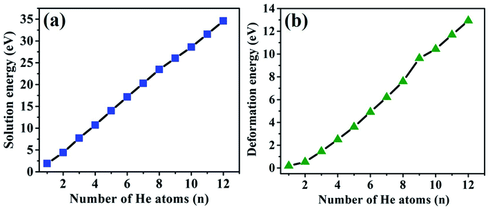 | ||
| Fig. 4 The relationship of solution energies and deformation energies of the Hen–VBe2 (n ≤ 8), Hen–VBe2VBe1 (n = 9, 10, and 11) and He12–VBe2VBe1VBe3 complexes with the number of implanted He atoms. | ||
3.3 Influence of the presence of H atoms on the nucleation of He bubbles and the trapping ability of monovacancies to H and He atoms
To explore the influence of the presence of H atoms on the nucleation of He bubbles, the capture behavior of H atoms in the Hen–VBe2 complexes (n ≤ 6), i.e., the synergistic effect of the H and He atoms, has been exhaustively investigated in the following paragraph. The solution energies, trapping energies, deformation energies and parts of the most stable configurations of the Hen–VBe2–Hm complexes (m is the number of H atoms) have been shown in Table 4 and Fig. 5, respectively.| Configuration | Esol (eV) | Etrap (eV) | Edef (eV) |
|---|---|---|---|
| He1–VBe2–H1 | 1.827 | −0.580 | 0.261 |
| He1–VBe2–H2 | 1.933 | −0.403 | 0.362 |
| He1–VBe2–H3 | 2.352 | −0.091 | 0.568 |
| He1–VBe2–H4 | 2.840 | −0.021 | 0.727 |
| He1–VBe2–H5 | 3.401 | 0.053 | 1.131 |
| He2–VBe2–H1 | 4.711 | −0.200 | 0.720 |
| He2–VBe2–H2 | 5.053 | −0.168 | 0.891 |
| He2–VBe2–H3 | 5.540 | −0.022 | 1.122 |
| He2–VBe2–H4 | 6.044 | −0.005 | 1.345 |
| He2–VBe2–H5 | 6.637 | 0.084 | 1.670 |
| He3–VBe2–H1 | 7.973 | −0.253 | 1.712 |
| He3–VBe2–H2 | 8.253 | −0.230 | 1.904 |
| He3–VBe2–H3 | 8.662 | −0.100 | 2.174 |
| He3–VBe2–H4 | 9.144 | −0.026 | 2.549 |
| He3–VBe2–H5 | 9.704 | 0.051 | 2.841 |
| He4–VBe2–H1 | 10.960 | −0.274 | 2.816 |
| He4–VBe2–H2 | 11.233 | −0.237 | 3.068 |
| He4–VBe2–H3 | 11.670 | −0.073 | 3.427 |
| He4–VBe2–H4 | 12.181 | 0.002 | 3.814 |
| He5–VBe2–H1 | 14.211 | −0.287 | 3.902 |
| He5–VBe2–H2 | 14.501 | −0.219 | 4.267 |
| He5–VBe2–H3 | 14.902 | −0.109 | 4.678 |
| He5–VBe2–H4 | 15.373 | −0.038 | 4.955 |
| He5–VBe2–H5 | 15.929 | 0.047 | 5.432 |
| He6–VBe2–H1 | 17.406 | −0.270 | 5.218 |
| He6–VBe2–H2 | 17.742 | −0.173 | 5.651 |
| He6–VBe2–H3 | 18.199 | −0.052 | 5.987 |
| He6–VBe2–H4 | 18.674 | −0.034 | 6.343 |
| He6–VBe2–H5 | 19.176 | −0.007 | 7.164 |
| He6–VBe2–H6 | 19.807 | 0.122 | 7.390 |
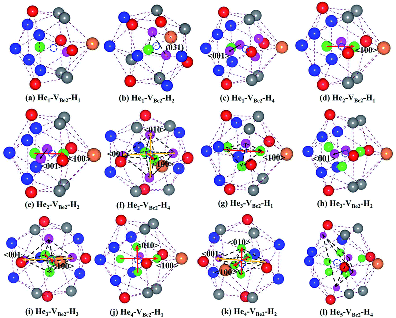
As we can see from Fig. 5, in the He1–VBe2–H1 complex, the distance between the H atom and He atom is 1.733 Å. In the most stable configuration of the He1–VBe2–H2 complex, the two H atoms, the He atom and VBe2 are located in the same plane of (031). The two H atoms and the He atom form the structure of an isosceles triangle, where the distances between the He atom and each H atom are 1.773 Å. In the configuration of the He1–VBe2–H4 complex, there are two H atoms distributed along the direction of 〈001〉. When another H atom is trapped by the He1–VBe2–H4 complex, the trapping energy becomes positive, implying that the He1–VBe2 complex could accommodate four H atoms at most.
In the He2–VBe2–H1 complex, the above mentioned dumbbell distributing along the direction of 〈100〉 still exists. However, the distance between two He atoms is 1.648 Å, which is larger than that in the He2–VBe2 complex (1.611 Å). In the He2–VBe2–H2 complex, two H atoms also distribute along the direction of 〈001〉. Besides, two He atoms and two H atoms are located in the same plane of (010). In the He2–VBe2–H4 complex, one new dumbbell structure along the direction of 〈010〉, which is composed of two H atoms and one VBe2, could obviously be observed. Meanwhile, four H atoms and two He atoms form the structure of an octahedron. The maximal trapping ability of the He2–VBe2 complex for H atoms is four.
The dumbbell distributing along the direction of 〈100〉 has been also observed in the He3–VBe2–H1 complex. Four atoms (one H atom and three He atoms) form the structure of a tetrahedron. In the He3–VBe2–H2 complex, two H atoms also distribute along the direction of 〈001〉. In the configuration of the He3–VBe2–H3 complex, three H atoms and three He atoms form the structure of an octahedron. It is found that the He3–VBe2 complex could also trap four H atoms.
The He4–VBe2 complex could trap three H atoms at most. The two dumbbells observed in the He4–VBe2 complex still exist. The structure of an octahedron, which is composed of two H atoms and four He atoms in the He4–VBe2–H2 complex, has been obviously observed.
In the He5–VBe2–H2 complex, two H atoms are no longer along the direction of 〈001〉. In the He5–VBe2–H3 complex, the dumbbell structure along the direction of 〈100〉 disappears. In the He5–VBe2–H4 complex, four H atoms form the structure of a tetrahedron. The He5–VBe2 complex could also trap four H atoms. However, the He6–VBe2 complex could trap up to five H atoms. Interestingly, in all the Hen–VBe2–Hm complexes (n ≤ 6, m ≤ 6), the He atoms are located in the core surrounding VBe2, while the H atoms are distributed on the surface of the core, forming a shell. This phenomenon has also been observed in W19 and Fe.46
It can be seen from Fig. 6(a) and (b) that the solution energies and deformation energies of the He and H atoms in the Hen–VBe2–Hm complexes (n ≤ 6, m ≤ 6) approximately linearly increase with the increase in the number of implanted He and H atoms, meaning that the degree of deformation increases with the sequential implantation of He and H atoms. The largest deformation will be induced by the He6–VBe2–Hm complexes. As we can see from Fig. 6(c), the He2–VBe2–Hm complexes have the maximal trapping energy. Besides, the trapping energy of all configurations will become positive when more than four H atoms are implanted around the Hen–VBe2 complexes. It is inferred that, in terms of their ability to trap H atoms, the Hen–VBe2 complexes will be saturated. The positive trapping energy means that it is difficult for the Hen–VBe2 complexes to trap H atoms, and the retention of H atoms will occur far away from the Hen–VBe2–Hm complexes. Besides, throughout the simulation of nucleation of Hen–VBe2–Hm complexes, no molecular H2 has been observed. The distances between any arbitrary two H atoms are larger than the bond length of molecular H2, 0.74 Å. Furthermore, it has also shown that the charge density between an arbitrary two H atoms is very low. The results indicate that the interaction between the arbitrary two H atoms is very weak, and the bond of molecular H2 cannot form. For example, in the He6–VBe2–H5 system, the minimal distance between two H atoms is 2.318 Å, which is larger than the bond length of molecular H2. On the other hand, as one can see from Fig. 7, the charge density between the two H atoms with a minimal distance between them of 2.318 Å is very low, which further indicates that no molecular H2 has formed.
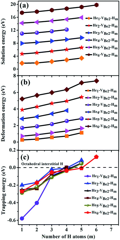 | ||
| Fig. 6 Relationship of (a) solution energies, (b) deformation energies and (c) trapping energies of the Hen–VBe2 complexes (n ≤ 6) with the number of implanted H atoms. | ||
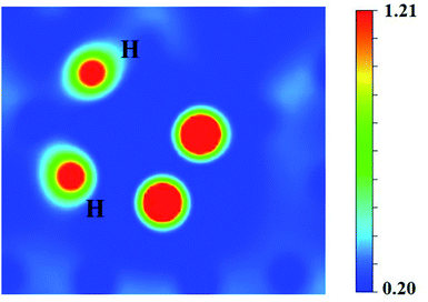 | ||
| Fig. 7 The charge density (e Å−3) between the two H atoms separated by a distance of 2.318 Å in the He6–VBe2–H5 system. | ||
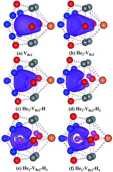
To better understand the mechanism for the trapping of H atoms by Hen–VBe2 complexes, the electronic structures of the He1–VBe2–Hm complexes have been calculated. As shown in Fig. 8, the purple curved surfaces represent the isosurface of charge density of 0.13 e Å−3. The individual He atom could not fill up the charge density hole. The surface of optimal electron density gradually shrinks as H atoms are sequentially implanted into the He1–VBe2 complex. When more than four H atoms are implanted, there is not enough isosurface for H atoms to combine with the complex. The residual H atoms would escape the complex due to the repulsion from other H atoms and will be trapped by other vacancies and complexes.
It has been firmly confirmed that beryllides are superior to pure Be in irradiation resistance.9,10 Therefore, alloying is an effective method not only for inhibiting the irradiation damage, but also improving the mechanical and thermodynamic properties of materials. Ternary or more complex beryllides may be more excellent as neutron multiplier materials. Besides, in experiment, researchers could develop new techniques to fabricate beryllides which have nanoscale grains. In the materials with small grains, there will be a large fraction of interfaces and grain boundaries,14 which also act as traps for the segregation and aggregation of transmutation-produced He and H atoms. As such, the concentrations of He and H atoms inside the grain will be relatively reduced. The irradiation induced swelling and damage could be well mitigated.
4 Conclusions
A systematic investigation has been performed to clarify the nucleation mechanism of a He bubble around a Be vacancy in bulk Be12Ti. The influence of the presence of H atoms on the nucleation of the He bubble, i.e., the synergistic effect of He and H atoms, has been further investigated. During the process of He bubble nucleation, dumbbell structures evolve with the number of implanted He atoms and finally disappear. In the Hen–VBe2 complexes (n ≤ 8), the nucleation of the He bubble is around a VBe2 monovacancy. It becomes interesting when another He atom is embedded into the He8–VBe2 complex. One new vacancy is induced and is occupied by one He atom in the He9–VBe2 complex. The subsequent He bubble nucleation is around the divacancy of VBe2VBe1. When an extra He atom is implanted into the He11–VBe2VBe1 complex, another new vacancy VBe3 is produced, but without the occupation of a He atom. It is inferred that the nucleation of the He bubble will be around the trivacancy of VBe2VBe1VBe3. It is difficult to get to saturation of trapped He atoms.In the study of the synergistic effect of He and H atoms, the implantation of H atoms into the Hen–VBe2 (n ≤ 6) complexes could influence the stability of existing dumbbells. On the other hand, some tetrahedral and octahedral structures are also obtained. The Hen–VBe2 (n ≤ 6) complexes could trap approximately four H atoms. The residual H atoms could not be accommodated due to the continuous shrinking of the isosurface of charge density, but could be trapped by other vacancies or complexes far away from the Hen–VBe2–H4 (n ≤ 6) complex. This simulation study provides a foundation to understand the evolution of the He bubble microstructure and the synergistic effect between He and H atoms in Be12Ti, which is favorable for better understanding the retention of irradiation-induced He and H atoms in neutron multiplying materials. This investigation could be helpful for the design and fabrication of more promising beryllides which could withstand a severe external environment.
Conflicts of interest
There are no conflicts to declare.Acknowledgements
This work is supported by the National Nature Science Foundation of China (Grant No. 11775102), the Strategic Priority Research Program of Chinese Academy of Sciences (Grant No. XDA21010202) and the Advanced Energy Science and Technology Guangdong Laboratory.References
- J. H. Kim and M. Nakamichi, J. Nucl. Mater., 2019, 519, 182–187 CrossRef CAS.
- D. V. Bachurin and P. V. Vladimirov, Intermetallics, 2018, 100, 163–170 CrossRef CAS.
- S. C. Middleburgh and R. W. Grimes, Acta Mater., 2011, 59, 7095–7103 CrossRef CAS.
- P. Vladimirov, C. Ferrero, V. Chakin, P. Kurinskiy, A. Moeslang, R. Pieritz, T. Weitkamp and E. Brun, Acta Mater., 2015, 88, 293–301 CrossRef CAS.
- V. Chakin, R. Rolli, R. Gaisin, U. H. Kramar, M. Nakamichi and M. Zmitko, Fusion Eng. Des., 2020, 161, 111938 CrossRef CAS.
- V. Chakin, R. Rolli, A. Moeslang, M. Klimenkov, M. Kolb, P. Vladimirov, P. Kurinskiy, H. C. Schneider, S. van Til, A. J. Magielsen and M. Zmitko, J. Nucl. Mater., 2013, 442, S483–S489 CrossRef CAS.
- V. Chakin, R. Rolli, A. Moeslang, P. Vladimirov, P. Kurinskiy, S. van Til, A. J. Magielsen and M. Zmitko, Fusion Eng. Des., 2013, 88, 2309–2313 CrossRef CAS.
- V. Chakin, J. Reimann, A. Moeslang, R. Latypov and A. Obukhov, Prog. Nucl. Energy, 2012, 57, 2–7 CrossRef CAS.
- K. Tsuchiya, T. Hoshino, H. Kawamura, Y. Mishima, N. Yoshida, T. Terai, S. Tanaka, K. Munakata, S. Kato, M. Uchida, M. Nakamichi, H. Yamada, D. Yamaki and K. Hayashi, Nucl. Fusion, 2007, 47, 1300–1306 CrossRef CAS.
- Y. Fujii, M. Miyamoto, J. H. Kim, M. Nakamichi, N. Murayoshi and H. Iwakiri, Nucl. Mater. Energy, 2016, 9, 233–236 CrossRef.
- S. Y. Binyukova, I. I. Chernov, B. A. Kalin and T. Swe, J. Nucl. Mater., 2007, 367–370, 500–504 CrossRef CAS.
- W. H. Hu, L. P. Guo, J. H. Chen, F. F. Luo, T. C. Li, Y. Y. Ren, J. P. Suo and F. Yang, Fusion Eng. Des., 2014, 89, 324–328 CrossRef CAS.
- S. J. Leclerc, M. L. Lescoat, F. Fortuna, L. Legras, X. Li and A. Gentils, J. Nucl. Mater., 2015, 466, 646–652 CrossRef.
- X. Y. Sun, F. D. Chen, H. Huang, J. W. Lin and X. B. Tang, Appl. Surf. Sci., 2019, 467–468, 1134–1139 CrossRef CAS.
- A. Založnik, M. J. Baldwin, R. P. Doerner, T. S. Selinger and S. Brezinsek, J. Nucl. Mater., 2018, 512, 25–30 CrossRef.
- I. B. Kupriyanov, G. N. Nikolaev, V. V. Vlasov, A. M. Kovalev and V. P. Chakin, J. Nucl. Mater., 2007, 367–370, 511–515 CrossRef CAS.
- E. Rabaglino, J. P. Hiernaut, C. Ronchi and F. S. Argentina, J. Nucl. Mater., 2002, 307–311, 1424–1429 CrossRef CAS.
- E. Abramov and D. Eliezer, J. Mater. Sci., 1992, 27, 2595–2598 CrossRef CAS.
- N. Juslin and B. D. Wirth, J. Nucl. Mater., 2013, 438, S1221–S1223 CrossRef CAS.
- W. A. Counts, C. Wolverton and R. Gibala, Acta Mater., 2010, 58, 4730–4741 CrossRef CAS.
- P. B. Zhang, J. J. Zhao and B. Wen, J. Nucl. Mater., 2012, 429, 216–220 CrossRef CAS.
- H. F. Zhang, B. D. Yao, L. Q. Shi, D. J. O’Connor, J. Huang, J. Y. Zhang, W. Ding and Y. X. Wang, Acta Mater., 2015, 97, 50–57 CrossRef CAS.
- Z. C. Meng, C. L. Wang, J. T. Liu, Y. L. Wang, X. L. Zhu, L. Yang and L. Huang, Phys. Chem. Chem. Phys., 2020, 22, 18040–18049 RSC.
- Y. G. Xu, X. J. Bai, X. H. Zha, Q. Huang, J. He, K. Luo, Y. H. Zhou, T. C. Germann, J. S. Francisco and S. Y. Du, J. Chem. Phys., 2015, 143, 114707 CrossRef PubMed.
- J. J. Liu, C. L. Wang, X. L. Zhu, J. T. Liu, X. M. Zhang, X. Q. Gou, W. S. Duan and L. Yang, Phys. Chem. Chem. Phys., 2018, 20, 18766–18774 RSC.
- L. Ferry, F. Virot, M. Barrachin, Y. Ferro, C. Pardanaud, D. Matveev, M. Wensing, T. Dittmar, M. Koppen and C. Linsmeier, Nucl. Mater. Energy, 2017, 12, 453–457 CrossRef.
- M. G. Ganchenkova and V. A. Borodin, Phys. Rev. B: Condens. Matter Mater. Phys., 2007, 75, 054108 CrossRef.
- P. V. Vladimirov and A. Moeslang, J. Nucl. Mater., 2013, 442, S694–S698 CrossRef CAS.
- P. B. Zhang, J. J. Zhao and B. Wen, J. Phys.: Condens. Matter, 2012, 24, 095004 CrossRef PubMed.
- X. L. Zhu, C. L. Wang, J. J. Liu, X. M. Zhang, H. Q. Deng, W. S. Duan and L. Yang, RSC Adv., 2018, 8, 35735 RSC.
- X. L. Zhu, C. L. Wang, Z. C. Meng, Y. L. Wang, H. Q. Deng, W. S. Duan and L. Yang, J. Nucl. Mater., 2019, 525, 7–13 CrossRef CAS.
- G. Kresse and J. Furthmüller, Phys. Rev. B: Condens. Matter Mater. Phys., 1996, 54, 11169–11186 CrossRef CAS PubMed.
- G. Kresse and J. Furthmüller, Comput. Mater. Sci., 1996, 6, 15–50 CrossRef CAS.
- P. E. Blöchl, Phys. Rev. B: Condens. Matter Mater. Phys., 1994, 50, 17953–17979 CrossRef PubMed.
- J. P. Perdew and Y. Wang, Phys. Rev. B: Condens. Matter Mater. Phys., 1992, 45, 13244 CrossRef PubMed.
- H. J. Monkhorst and J. D. Pack, Phys. Rev. B: Solid State, 1976, 13, 5188–5192 CrossRef.
- Q. Zhao, Z. Zhang, M. Huang, X. D. Zhang and X. P. Ouyang, Nucl. Instrum. Methods Phys. Res., Sect. B, 2020, 470, 48–55 CrossRef CAS.
- E. Gillam, H. P. Rooksby and L. D. Brownlee, Acta Crystallogr., 1964, 17, 762–763 CrossRef CAS.
- M. L. Jackson, P. A. Burr and R. W. Grimes, Acta Crystallogr., Sect. B: Struct. Sci., Cryst. Eng. Mater., 2016, B72, 277–280 CrossRef PubMed.
- A. Zalkin, D. E. Sands, R. G. Bedford and O. H. Krikorian, Acta Crystallogr., 1961, 14, 63–65 CrossRef CAS.
- M. L. Jackson, P. A. Burr and R. W. Grimes, Nucl. Fusion, 2017, 57, 086049 CrossRef.
- X. K. Liu, Q. J. Feng, B. Tang, J. Zheng, Z. Zheng, W. Zhou, J. T. Tian and J. Wang, RSC Adv., 2019, 9, 5302 RSC.
- A. Alkhamees, H. B. Zhou, Y. L. Liu, S. Jin, Y. Zhang and G. H. Lu, J. Nucl. Mater., 2013, 437, 6–10 CrossRef CAS.
- M. A. Tschopp, F. Gao and K. N. Solanki, Acta Mater., 2017, 124, 544–555 CrossRef CAS.
- W. Counts, C. Wolverton and R. Gibala, Acta Mater., 2011, 59, 5812–5820 CrossRef CAS.
- E. Hayward and C. Deo, J. Phys.: Condens. Matter, 2012, 24, 265402 CrossRef PubMed.
Footnote |
| † Contributed equally to this work. |
| This journal is © The Royal Society of Chemistry 2021 |

