 Open Access Article
Three-dimensional thiophene-diketopyrrolopyrrole-based molecules/graphene aerogel as high-performance anode material for lithium-ion batteries†
Shengxian Hou ,
Xinyao Zhang,
Pengfei Zhou
 ,
Shuhai Chen,
Hongtao Lin
 *,
Jin Zhou
 ,
Shuping Zhuo
 * and
Yuying Liu*
School of Chemistry and Chemical Engineering, Shandong University of Technology, Zibo 255049, China. E-mail: linht@sdut.edu.cn; zhuosp_academic@yahoo.com; lyy999999@163.com
First published on 28th October 2021
Abstract
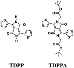
Herein, 3,6-di(thiophen-2-yl)-2,5-dihydropyrrolo[3,4-c]pyrrole-1,4-dione (TDPP) and di-tert-butyl 2,2′-(1,4-dioxo-3,6-di(thiophen-2-yl)pyrrolo[3,4-c]pyrrole-2,5(1H,4H)-diyl)diacetate (TDPPA) were synthesized, which were then loaded in graphene aerogels. The as-prepared thiophene-diketopyrrolopyrrole-based molecules/reduced graphene oxide composites for lithium-ion battery (LIB) anode composites consist of DPPs nanorods on a graphene network. In relation to the DPPs part, embedding DPPs nanorods into graphene aerogels can effectively reduce the dissolution of DPPs in the electrolyte. It can serve to prevent electrode rupture and improve electron transport and lithium-ion diffusion rate, by partially connecting DPPs nanorods through graphene. The composite not only has a high reversible capacity, but also shows excellent cycling stability and performance, due to the densely distributed graphene nanosheets forming a three-dimensional conductive network. The TDPP60 electrode exhibits high reversible capacity and excellent performance, showing an initial discharge capacity of 835 mA h g−1 at a current density of 100 mA g−1. Even at a current density of 1000 mA g−1, after 500 cycles, it still demonstrates a discharge capacity of 303 mA h g−1 with a capacity retention of 80.7%.
1. Introduction
In recent years, the rapid development of lithium-ion batteries has driven revolutionary advances in smartphones, laptops, electric vehicles and many other fields.1,2 There is a focus not only on improving battery performance, but also on safety, resource constraints and environmental factors.3–5 Among them, organic electrode materials have attracted much attention for their high power density, simple and easy availability of raw materials, and environmental friendliness.2,6,7 Because of their different structures and tunable redox voltages, conjugated carbonyl compounds are one of the most attractive classes of organic electrode materials in the family.8,9 Since the majority of them possess relatively high redox potentials, they are often used as cathode materials. When the redox-active carbonyl groups are located in carboxyl groups, they still have the potential to undergo electrochemical reactions at lower voltages, which makes it possible to use them as anode materials.10–12Nevertheless, the irreversible dissolution of organic molecules in the nonprotonic electrolyte leads to capacity degradation during cycling, which largely limits their application in rechargeable battery systems. Fortunately, recent studies have shown that doping organic materials into highly conductive carbon substrates can provide nanoconfinement effects that improve their electrical conductivity while overcoming solubility in the electrolyte.13,14 On the other hand, the introduction of graphene or carbon into carbonyl compounds can increase the utilization efficiency of carbonyl compounds and improve the performance of the LIB anodes. It has been recently demonstrated that the introduction of carbonyl compounds into graphene or carbon nanotubes as a means to increase the efficiency of conjugated carbonyl compound utilization and improve the electrochemical performance of the resulting composites as LIB anodes.15–17
Graphene aerogel is a new highly porous, ultra-lightweight material with high electrical conductivity, large surface area and chemical stability, characteristics that make it well suited for applications in energy storage.15,18 Therefore, the incorporation of organic molecules into graphene aerogels with compatible three-dimensional (3D) porous structures seems to be the most applicable strategy to improve the electrochemical performance of organic LIB anodes.
In this paper, we used a one-step solution process to fabricate a pyrrolopyrrole compound/graphene aerogel as the anode material for LIBs. The organic molecule is stabilized by π–π interactions between graphene and pyrrolopyrrole core, with the main redox site provided by the conjugated carbonyl group. As expected, the TDPP/graphene aerogel as an anode material for LIBs showed a high initial capacity of 835 mA h g−1 at a current density of 100 mA g−1, long cycle performance without any degradation after 100 cycles, and excellent rate performance (508 mA h g−1 even at 1000 mA g−1) (Scheme 1).
2. Characterization
2.1 Structure characterization
The synthesized routes of TDPP and TDPPA are shown in the Scheme S1.†19–22 The molecular structure of DPPs was characterized by 1H NMR spectra. And the 1H NMR spectra were recorded on a Bruker AVANCE III 400 NMR. Chloroform-D and tetramethylsilane were used as the solvent and internal standard, respectively. FT-IR measurements were performed on a Nicolet 5700 spectrometer within a wavenumber region of 4000–400 cm−1. XRD data were collected on an Ultima IV powder X-ray diffractometer with Cu Kα radiation (20 keV) in the 2θ ranges of 5° and 40°. SEM was performed on a Sirion 200 at a working voltage of 200 kV. XPS measurements were performed on Thermo ESCALAB 250XI electron spectrometer. According to the original XPS data, the standard peak of C 1s before cycling was modified from 284.73 to 284.8 eV. In addition, the standard peaks of C 1s were modified from 284.83 to 284.8 eV after lithiation process and 284.78 to 284.8 eV after the delithiation process. Thermogravimetric analysis (TGA) was performed using a DSC Q100 spectrometer. Ramp up from room temperature to 700 °C at a heating rate of 10 °C min−1 in a nitrogen atmosphere.2.2 Electrochemical measurements
Measurement of electrochemical performance was done using CR2032 coin-type cell. The electrode slurries were prepared by blending 80 wt% active material (DPPs/RGO), 10 wt% polyvinylidene fluoride (PVDF) binder and 10 wt% Super P in 1-methyl-2-pyrrolidinone (NMP) to form a slurry. The electrode slurries were then coated on a piece of Cu foil (10 μm thick). The prepared electrodes were vacuum dried at 80 °C for 12 h and then cut into 12 mm diameter discs. The DPPs/RGO materials were loaded at 0.3–0.46 mg cm−2. In the assembly of LIBs, lithium metal foil was used as the counter electrode and the electrolyte was 1 M lithium hexafluorophosphate (LiPF6) dissolved in ethylene carbonate (EC), ethyl methyl carbonate (EMC) and dimethyl carbonate (DMC) (1![[thin space (1/6-em)]](https://www.rsc.org/images/entities/char_2009.gif) :
:![[thin space (1/6-em)]](https://www.rsc.org/images/entities/char_2009.gif) 1
1![[thin space (1/6-em)]](https://www.rsc.org/images/entities/char_2009.gif) :
:![[thin space (1/6-em)]](https://www.rsc.org/images/entities/char_2009.gif) 1, v/v), using polypropylene (PP) Celgard 2400 porous membrane as the separator. Cells were assembled in an argon glove box (water and oxygen content less than 0.1 ppm). The electrochemical properties of the electrode materials were characterized on a BTSDA (Shenzhen Xinhua Instruments Co, Ltd.) electrochemical workstation. The IVIUM electrochemical workstation was used to perform electrochemical impedance spectroscopy (EIS) and cyclic voltammetry (CV) tests.
1, v/v), using polypropylene (PP) Celgard 2400 porous membrane as the separator. Cells were assembled in an argon glove box (water and oxygen content less than 0.1 ppm). The electrochemical properties of the electrode materials were characterized on a BTSDA (Shenzhen Xinhua Instruments Co, Ltd.) electrochemical workstation. The IVIUM electrochemical workstation was used to perform electrochemical impedance spectroscopy (EIS) and cyclic voltammetry (CV) tests.
2.3 Preparation of DPPs/RGO composite
Graphene oxide (GO) suspensions were prepared using an improved chemical exfoliation method.23 Peel the pre-prepared aqueous GO suspension by vigorous ultrasound for 30 min before use. Typically, different amounts (40, 60, and 80 mg) of 3,6-di(thiophen-2-yl)-2,5-dihydropyrrolo[3,4-c]pyrrole-1,4-dione (TDPP) were dispersed in 40 mL of GO aqueous solution (2 mg mL−1). Subsequently, the suspension was then sonicated for 20 minutes and transferred to a 50 mL stainless steel autoclave lined with Teflon and sealed tightly. Treatment at 180 °C for 12 h to form the 3D skeletal structure and simultaneously reduce graphene oxide. Subsequently, the Teflon autoclave was cooled and the resulting hydrogels were freeze-dried in a freeze-dryer. Here, different masses of TDPP were dispersed in GO aqueous solutions, denoted herein as TDPP40, TDPP60, and TDPP80. TDPPA (di-tert-butyl 2,2′-(1,4-dioxo-3,6-di(thiophen-2-yl)pyrrolo[3,4-c]pyrrole-2,5(1H,4H)-diyl)diacetate) samples are prepared in the same way, and the amount of organics is the same as that of TDPPs.3. Results and discussion
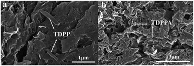
A representative preparation process of the composite is illustrated schematically in Fig. 1. GO and DPPs were first dispersed in an aqueous solution by ultrasonic treatment. Subsequently, the mixture solution was treated under solvothermal condition, through which the GO was reduced and the DPPs were self-assembles on the GO surface to form a 3D graphene framework. Finally, the graphene aerogel-coated DPPs particles were obtained by freeze-drying. Aerogels are known to show ultralight and porous characteristics, which are advantageous for composite materials as anode materials for LIBs.16,18,24First, we observed the morphological features of TDPP60, TDPPA60 and the original DPPs by SEM images. As shown in Fig. S1,† the original TDPP and TDPPA show rod-like particles produced by spontaneous stacking of molecules. As shown in Fig. 2, the highly interconnected 3D graphene frameworks are clearly observed in DPPs/RGO composite. In the TDPP/RGO composite material, TDPP is attached to the sheet-layer reduced graphene oxide in the form of nanorods, with an average length of 550–750 nm (Fig. 2a). TDPP was almost completely wrapped in the graphene 3D frame structure, only a few TDPP nanorods attached to the graphene surface (Fig. 2a). Fig. 2b shows that TDPPA particles with sizes of 130–270 nm are not only present on the surface but are also encapsulated inside the 3D graphene framework. TDPPA nanorods are attached to RGO, and the highly conductive RGO nanosheets connect adjacent TDPPA particles together between them to form a 3D conductive network. In general, the graphene substrate can effectively inhibit the excessive growth and accumulation of DPP molecules. Compared with the original loosely stacked DPPs nanorods, the porous structure formed by the DPP/RGO composite is more conducive to the transport of Li+ (Fig. S4†). In addition, the results of thermogravimetric analysis show that the DPPs/RGO composites are stable at temperatures of 200 °C, which is beneficial for the charging and discharging of the LIBs (Fig. S2†).
FT-IR spectroscopy is used to compare the chemical structure of TDPP/RGO and TDPPA/RGO composites (Fig. 3). For the TDPP and TDPPA, there were two broad characteristic peaks at 1597 and 1645 cm−1, which were related to the stretching vibration of the C![[double bond, length as m-dash]](https://www.rsc.org/images/entities/char_e001.gif) O and C
O and C![[double bond, length as m-dash]](https://www.rsc.org/images/entities/char_e001.gif) C functional groups. Moreover, a sharp infrared vibration band at 1740 cm−1 for TDPPA was observed, which correspond to C
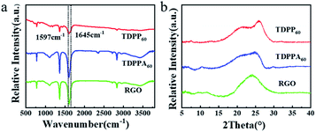
C functional groups. Moreover, a sharp infrared vibration band at 1740 cm−1 for TDPPA was observed, which correspond to C![[double bond, length as m-dash]](https://www.rsc.org/images/entities/char_e001.gif) O stretching vibrations belonging to the tert-butyl acetate groups.25 The above mentioned characteristic peaks for TDPP and TDPPA can be found in TDPP60 and TDPPA60 composites, respectively, indicating that DPPs organic molecules have been successfully incorporated into the 3D hybrid architecture. In general, as the content of DPPs increases, DPPs/RGO composites show more obvious characteristic peaks, and as the content of DPPs decreases, they show weaker characteristic peaks. Powder X-ray diffraction patterns of TDPP60 and TDPPA60 composites reveal the amorphous broad peak at 2θ = 15–25° (Fig. 3b),26–28 which indicates that theses DPPs/RGO composites are mainly disordered π–π stacked. As show in Fig. 3b, the XRD pattern shows an obvious broad peak at 2θ = 20–25°, which indicates that GO is reduced by thermal reduction and the resulting RGO is ordered and has a certain three-dimensional structure.16,24
O stretching vibrations belonging to the tert-butyl acetate groups.25 The above mentioned characteristic peaks for TDPP and TDPPA can be found in TDPP60 and TDPPA60 composites, respectively, indicating that DPPs organic molecules have been successfully incorporated into the 3D hybrid architecture. In general, as the content of DPPs increases, DPPs/RGO composites show more obvious characteristic peaks, and as the content of DPPs decreases, they show weaker characteristic peaks. Powder X-ray diffraction patterns of TDPP60 and TDPPA60 composites reveal the amorphous broad peak at 2θ = 15–25° (Fig. 3b),26–28 which indicates that theses DPPs/RGO composites are mainly disordered π–π stacked. As show in Fig. 3b, the XRD pattern shows an obvious broad peak at 2θ = 20–25°, which indicates that GO is reduced by thermal reduction and the resulting RGO is ordered and has a certain three-dimensional structure.16,24
Cyclic voltammetry (CV) studies are carried out to measure the reversibility by scanning the potential window between 0.01 and 3.0 V versus Li/Li+ at a scan rate of 0.1 mV s−1 in Fig. 4. As shown in Fig. 4a, a strong reduction peak appears at 0.57 V in the first cathodic scan, which corresponds to the formation of the SEI film and is associated with the appearance of the irreversible capacity in the first cycle. This reduction peak diminishes or disappears in subsequent cycles, indicating the formation of a stable SEI film (Fig. 4a). It should be noted that this reduction peak may be associated with the lithium ion storage of several layers of defective graphene. In the illustration in Fig. 4a and b, all of the TDPP60 and TDPPA60 have obvious insertion/extraction peaks of lithium-ion, such as TDPP60 lithiation peak (Ered) at 1.49 V, 2.24 V and 2.64 V, delithiation peak (Eox) at 1.88 V, and 2.59 V, TDPPA60 (Ered) at 1.48 V, (Eox) at 1.87 V and 2.30 V. In the subsequent cycles, the CV curves of TDPP60 almost overlap, which indicates that the TDPP60 electrode has good electrochemical reversibility and stability. As shown in Fig. S3,† the CV curves of different ratios of DPPs/RGO composites have basically the same positions of the main insertion/extraction peaks of lithium-ion and show similar electrochemical stability.
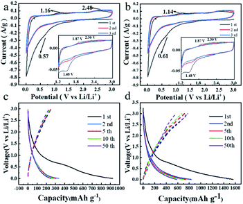 | ||
| Fig. 4 CV curves of the DPPs at a scan rate of 0.1 mV s−1 (a) TDPP60, (b) TDPPA60, and galvanostatic charge/discharge profiles at a constant current of 100 mA g−1 (c) TDPP60, (d) TDPPA60. | ||
During the first discharge, the specific discharge capacities of TDPP60, and TDPPA60 were 924 mA h g−1 and 1562 mA h g−1, respectively. It should be noted that some carbonyl groups are present in the pre-formed GO nanosheets during the preparation process. During the thermal reduction process, most of the carbonyl groups in the RGO are removed in the form of CO2 and CO. Even though a very small amount of carbonyl group is still retained in the generated RGO, its contribution to the capacity is negligible compared to the total mass of TDPP/RGO and TDPPA/RGO composites.24 In Fig. 4a, no oxidation and reduction peaks associated with other carbonyl-containing organics were observed, further indicating that the reversible capacity is only related to the carbonyl group in TDPP and TDPPA. TDPP60 demonstrated reversible capacities of 387 mA h g−1 and 594 mA h g−1 in subsequent cycles, respectively, showing overlapping charge/discharge curves, which indicates the excellent stability.29–31
As shown in Fig. 5a, the TDPP electrodes exhibit an initial discharge capacity of 321 mA h g−1. With the increasing of the cycle number, the specific discharge capacity of the TDPP electrode clearly shows an upward trend. The discharge capacity of the TDPP electrode increases from 115 mA h g−1 in the second cycle to 439 mA h g−1 in the 1700th cycle, and become stalely in subsequent cycles.32–34 The TDPP40, TDPP60 and TDPP80 shows higher capacities of 1319 mA h g−1, 1378 mA h g−1 and 761 mA h g−1, respectively (Fig. 5a). In contrast, TDPPs/RGO shows much higher discharge capacity than that of TDPP. For TDPP40, TDPP60 and TDPP80 electrode with different mass ratios of organic molecule, the change of RGO doping ratio seems to have no effect on their discharge specific capacity (Fig. 5a and S6†). Interestingly, as the proportion of TDPP in the TDPP/RGO composite gradually increases, the specific discharge capacity of TDPP/RGO decreases in the first 250 cycles. On the whole, TDPP/RGO composites show higher discharge capacity and cycle stability compared with those of TDPP.
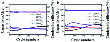 | ||
| Fig. 5 (a) TDPP/RGO and (b) TDPPA/RGO cycling performance for the electrodes conducted at a current density of 1000 mA g−1 between 0.01 V to 3.0 V over 2000 cycles. | ||
As shown in Fig. 5b, TDPPA exhibited the discharge capacity of 125.3 mA h g−1 during the first cycle. Unlike the property of TDPPA, TDPPA/RGO composite exhibits a higher specific discharge capacity. TDPPA40, TDPPA60 and TDPPA80 exhibit initial specific discharge capacities of 530, 1176 and 1022.6 mA h g−1, respectively. As the increase of the mass ratio of the TDPPA in the TDPPA/RGO composite material increasing, its specific discharge capacity also increases accordingly. However, we find that higher content of TDPPA will reduce the cycle stability of TDPPA/RGO composites. TDPPA60 showed a discharge specific capacity of about 472 mA h g−1 after 2 cycles. After 500 cycles, it still showed a discharge specific capacity of 276 mA h g−1, and the capacity retention rate was about 58.47%. TDPPA40 shows a lower specific discharge capacity of about 220 mA h g−1, and only shows a specific discharge capacity of about 230 mA h g−1 after 500 cycles. TDPPA80 shows a higher specific discharge capacity of about 510 mA h g−1, and only shows a specific discharge capacity of about 499 mA h g−1 after 500 cycles with a capacity retention rate of 98.22%. It is worth noting that TDPPA80 maintains the trend of gradual increase in capacity of TDPPA as the number of cycling increasing. The discharge specific capacity of TDPPA80 decreased from 508 mA h g−1 in the second cycle to 351 mA h g−1 in the 40th cycle, and then gradually increased to 592 mA h g−1 in the 500th cycle, and reached the maximum value. We believe that the main structure of the pyrrolopyrrole molecule is destroyed due to the insertion and extraction of lithium ions from TDPP, and the unsaturated carbon in the pyrrolopyrrole molecule inevitably participates in the lithiation/de-lithiation process for TDPP electrode. The above reasons may contribute to the upward trend during cycling for the TDPP electrode. In the TDPP/RGO composite electrode, the organic molecules are stabilized by the π–π interaction between the graphene and the pyrrolopyrrole core, which largely avoids the structural destruction of the TDPP molecules during the cycle. The main redox sites are provided by the conjugated carbonyl group, thus the TDPP/RGO composite electrode exhibits stable discharge capacity during cycling.
Fig. 6 shows the rate capability of the TDPP60 and TDPPA60 with the current density increased from 100 to 1000 mA g−1. The TDPP60 electrode exhibits a steadily discharge capacity, and the discharge specific capacity is stable at 15 cycles of 838 mA h g−1 at 100 mA g−1. When the current density is increased to 200 and 500 mA g−1, the electrode can still provide high reversible capacity of about 506 and 380 mA h g−1, respectively. When cycled at different current densities, the electrode maintains a coulombic efficiency higher than 98%.
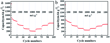 | ||
| Fig. 6 (a) Rate capability of TDPP60, and (b) TDPPA60 with the current density increased from 100 to 1000 mA g−1 in a stepwise manner. | ||
The rate capability of RGO-wrapped TDPP/RGO composites is much better than that of bare DPP (Fig. 6 and S7†). Even at higher current densities, TDPP/RGO composites can provide high discharge capacity and good cycle stability, as shown in Fig. 6a. The doping of RGO not only improves the conductivity but facilitates the rapid diffusion of Li+ in the electrode, which results in excellent multiplicative performance of TDPP60 and TDPPA60. TDPPA60 also showed a similar trend of capacity growth to that of TDPP. At a current density of 100 mA g−1, TDPP60 exhibits discharge specific capacities of approximately 699 mA h g−1. As the current density is increased to 1000 mA g−1, the discharge specific capacity drops to 276 mA h g−1. As the current density decreased to 100 mA g−1, the specific discharge capacity recovered to 587 mA h g−1, and stabilized.
The solvothermal reduction method enables the effective combination of DPPs particles with the 3D graphene framework, which accelerates the charge transfer of DPPs and improves the electrical conductivity of the electrode material, enabling the redox reaction to be completed rapidly. We further verified this by electrochemical impedance spectroscopy (EIS).35 All Nyquist plots consist of two parts, a compressed semicircle in the high and high frequency regions and a sloping line in the low frequency region, as shown in Fig. 7.18 All EIS plots can be fitted with the same equivalent circuit pattern (inset in Fig. 7), where Rs is related to the ohmic and solution resistance, where Rct denotes the charge transfer resistance between the electrolyte interface and the electrode. CPE is the constant phase angle element associated with the double layer capacitance, and Zw is the Warburg impedance associated with the ion diffusion impedance in the active material.
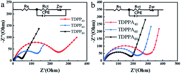 | ||
| Fig. 7 Electrochemical impedance spectra of different samples at a range from 100 kHz to 10 mHz. (a) TDPPs and (b) TDPPAs. | ||
The corresponding values of Rct and Rs in the EIS diagram are summarized in Table S1.† The TDPP/RGO composites have a much smaller Rct value than bare DPP, especially TDPP40. The Rct values decreased significantly with the increase of RGO content in the composites. This result suggests that the conductivity can be effectively increased by incorporating highly conductive RGO into DPP, which leads to high reversible capacity. In addition, pure DPP has a larger slope in the low-frequency region, showing a higher Warburg impedance. These results suggest that the high electrical conductivity of graphene and its π–π interactions with DPP molecules accelerate the passage of Li+ ions through the SEI membrane, leading to faster kinetics of intra-electrode migration as well as charge transfer reactions.36 In addition, the resistance of the SEI film is thus reduced due to the presence of RGO.37 This may be due to the fact that the 3D structure of the DPP/RGO composite reduces the direct contact of the DPP with the electrolyte, thus suppressing side reactions (such as dissolution of DPP molecules and the appearance of lithium dendrites) during long-term cycling.
In order to explore the lithium storage mechanism further, the structure changes of the DPPs electrode were analyzed by FT-IR patterns (Fig. 8). Notably, there are no obvious changes for FT-IR of the TDPP60 and TDPPA60 during the 2000 cycle. There are two characteristic peaks at 1440 and 1645 cm−1, which are related to the stretching vibration of the C![[double bond, length as m-dash]](https://www.rsc.org/images/entities/char_e001.gif) O and C
O and C![[double bond, length as m-dash]](https://www.rsc.org/images/entities/char_e001.gif) C functional groups. This further proves the electrochemical stability of TDPP60 and TDPPA60. In addition, the sharp infrared vibration band of TDPPA at 1740 cm−1 corresponding to the C
C functional groups. This further proves the electrochemical stability of TDPP60 and TDPPA60. In addition, the sharp infrared vibration band of TDPPA at 1740 cm−1 corresponding to the C![[double bond, length as m-dash]](https://www.rsc.org/images/entities/char_e001.gif) O stretching vibration of the tert-butyl acetate group is not observed, which indicates that the tert-butyl acetate group participates in the oxidation–reduction reaction of the anode.
O stretching vibration of the tert-butyl acetate group is not observed, which indicates that the tert-butyl acetate group participates in the oxidation–reduction reaction of the anode.
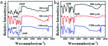 | ||
| Fig. 8 The ex situ FT-IR patterns for the DPPs electrodes obtained at different cycling states. (a) TDPP60 and (b) TDPPA80. | ||
In order to further explore the storage mechanism of lithium, the structural changes on the TDPPA60 electrode were analyzed by X-ray photoelectron spectroscopy (XPS) (Fig. 9). For comparison, the TDPPA60 electrode was disassembled after the third full charge and discharge cycle (Fig. 9b and c). Before the electrochemical cycle, no signal of lithium or phosphorus was found in the XPS spectrum of the TDPP60 electrode (Fig. 9a). Later, obvious signals of lithium and phosphorus appeared after the discharge process, indicating that the lithiation reaction of the TDPP60 electrode occurred (Fig. 9b). In addition, after the delithiation reaction of the TDPP60 electrode, the signal about lithium is still clearly visible, which may be caused by the strong irreversible reaction of the TDPP60 electrode in the charging reaction (Fig. 9c). In addition, the C 1s and O 1s spectra of the TDPP60 electrode in different electrochemical states also indicate the structural changes of the TDPPA60 molecule during the electrochemical process.2
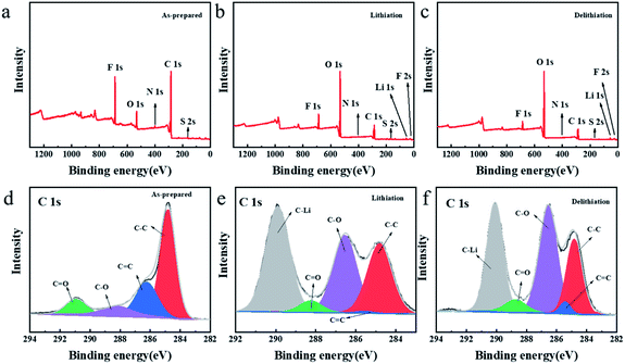 | ||
| Fig. 9 XPS spectra of the surface for the TDPPA60 electrodes (a and d) as-prepared, (b and e) after 3rd-cycle lithiation process, (c and f) after 3rd-cycle delithiation process. | ||
As shown in Fig. 9, there are significant differences in the collected C 1s spectra under different electrochemical conditions, indicating that the TDPPA60 electrode has undergone structural changes in the electrochemical reaction. As shown in Fig. 9d, the C 1s for as-prepared TDPP60 electrode includes four main components, namely C![[double bond, length as m-dash]](https://www.rsc.org/images/entities/char_e001.gif) C (286.24 eV), C–C (284.80 eV), C–O (288.24 eV) and C
C (286.24 eV), C–C (284.80 eV), C–O (288.24 eV) and C![[double bond, length as m-dash]](https://www.rsc.org/images/entities/char_e001.gif) O (288.73 eV), respectively.38–40 After the lithiation reaction, a new strong peak appeared, corresponding to the C–Li bond at 290.95 eV, which can be attributed to the lithiation reaction on the C
O (288.73 eV), respectively.38–40 After the lithiation reaction, a new strong peak appeared, corresponding to the C–Li bond at 290.95 eV, which can be attributed to the lithiation reaction on the C![[double bond, length as m-dash]](https://www.rsc.org/images/entities/char_e001.gif) C bond (Fig. 9e). At the same time, after the subsequent delithiation reaction, the peak intensity of the C–Li bond is significantly weakened, which indicates that a reversible lithiation-delithiation process has occurred on the C
C bond (Fig. 9e). At the same time, after the subsequent delithiation reaction, the peak intensity of the C–Li bond is significantly weakened, which indicates that a reversible lithiation-delithiation process has occurred on the C![[double bond, length as m-dash]](https://www.rsc.org/images/entities/char_e001.gif) C bond (Fig. 9f). In addition, the peak intensity of the C
C bond (Fig. 9f). In addition, the peak intensity of the C![[double bond, length as m-dash]](https://www.rsc.org/images/entities/char_e001.gif) O bond was significantly weakened after the lithiation reaction, and recovered after the delithiation reaction, which also proved the reversibility of the C
O bond was significantly weakened after the lithiation reaction, and recovered after the delithiation reaction, which also proved the reversibility of the C![[double bond, length as m-dash]](https://www.rsc.org/images/entities/char_e001.gif) O group in the electrochemical reaction.40
O group in the electrochemical reaction.40
As shown in Fig. 10a and c, after the electrochemical experiments, it can be observed that TDPP60 is more affected than TDPPA60 during charging and discharging, on the one hand, due to the removal of lithium during de-lithiation leading to significant cracks on the surface of the electrode. The presence of cracks decreases the Li+ transport rate. On the other hand, TDPP60 wrapped in the graphene aerogel of the electrode shows better stability in electrochemical experiments. This behavior is likely to be due to the presence of graphene aerogel significantly reducing the dissolution of TDPP in LiPF6 electrolyte. Many microrods and particles appears for as-prepared TDPP60 electrode material (Fig. 2a). After 2000 cycles, the TDPP60 electrode material transforms into regular nanoparticles with a diameter of about 100–200 nm (Fig. 10f). In addition, the TDPPA60 electrode material before cycling exhibited irregular microrods and particles before cycling (Fig. 2b). As shown in the Fig. 10b, most of the TDPPA60 electrodes remained intact and uniformly distributed in the 3D graphene framework after 200 cycles, indicating that the presence of the 3D graphene framework significantly reduced the dissolution of the DPP molecules in the electrolyte (Fig. S5†). From the SEM images of TDPPA60 in Fig. 10d and f, it can be seen that the regular TDPPA microrods almost completely disappear and transform into an amorphous structure after repeated lithiation and delithiation reactions. Therefore, the 3D RGO framework can not only buffer the volume expansion and contraction of TDPPA microrods during lithiation and de-lithiation, but also prevent the electrode material from cracking during cycling due to the elasticity of the graphene sheet, maintaining good integrity of the entire electrode structure.
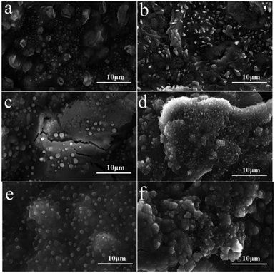 | ||
| Fig. 10 SEM images for the DPPs electrodes (a, c and e) TDPP60 and (b, d and f) TDPPA60 at a current density of 1000 mA g−1. (a and b) 200 cycles, (c and d) 500 cycles, (2000) cycles. | ||
4. Conclusions
In summary, DPPs/RGO composites were successfully prepared by a simple hydrothermal process. On the one hand, highly conductive RGO nanosheets are wrapped around the outside of the DPPs, while on the other hand, adjacent DPP nanorods are connected by RGO to form a dense layer-like structure. Due to the π–π interaction between graphene and pyrrolopyrrole core, the DPP molecules are closely connected to the RGO, forming a 3D conductive network that facilitates the rapid diffusion of lithium ions in the electrode material. The DPPs/RGO composite electrode in lithium ion batteries exhibits excellent electrochemical performance. The charge capacity of the TDPPA60 electrode is tested to be 472 mA h g−1 at the high current density of 1 A g−1. After 2000 charge and discharge cycles, the retained capacity of the TDPPA60 anode material is measured to be 190 mA h g−1 at the current density of 1 A g−1. These results suggest that the excellent electrochemical performance of DPP/RGO composite anode materials is due to the synergistic effect of DPPs molecules and graphene, the RGO can provide strong support to the DPPs nanoparticles and avoid being dissolved during charging and discharging. The above-mentioned excellent electrochemical properties, together with abundant material resources and convenient preparation processes, make DPPs/RGO composites a low-cost anode material for large-scale lithium-ion batteries. In addition, the RGO aerogel in this work expands the scope of seeking effective methods to improve the electrochemical properties of other organic electrode materials.Conflicts of interest
There are no conflicts to declare.Acknowledgements
This work was supported by the National Natural Science Foundation of China (No. 21403130, 21901146, 21576158, 21576159), the Natural Science Foundation of Shandong Province (ZR2020MB054, ZR2014BQ028, 2015ZRB01765).Notes and references
- Y. Shi, X. Zhou and G. Yu, Acc. Chem. Res., 2017, 50, 2642–2652 CrossRef CAS PubMed.
- J. J. Shea and C. Luo, ACS Appl. Mater. Interfaces, 2020, 12, 5361–5380 CrossRef CAS PubMed.
- V. Etacheri, R. Marom, R. Elazari, G. Salitra and D. Aurbach, Energy Environ. Sci., 2011, 4, 3243 RSC.
- B. Scrosati, J. Hassoun and Y.-K. Sun, Energy Environ. Sci., 2011, 4, 3287 RSC.
- D. Lin, Y. Liu and Y. Cui, Nat. Nanotechnol., 2017, 12, 194–206 CrossRef CAS PubMed.
- C. Xue, X. Zhang, S. Wang, L. Li and C. W. Nan, ACS Appl. Mater. Interfaces, 2020, 12, 24837–24844 CrossRef CAS PubMed.
- S. Y. An, T. B. Schon and D. S. Seferos, ACS Omega, 2020, 5, 1134–1141 CrossRef CAS PubMed.
- H. Wang, C.-J. Yao, H.-J. Nie, K.-Z. Wang, Y.-W. Zhong, P. Chen, S. Mei and Q. Zhang, J. Mater. Chem. A, 2020, 8, 11906–11922 RSC.
- K. Amin, L. Mao and Z. Wei, Macromol. Rapid Commun., 2019, 40, e1800565 CrossRef PubMed.
- M.-H. Li, S.-Y. Zhang, H.-Y. Lv, W.-J. Li, Z. Lu, C. Yang and G.-H. Zhong, J. Phys. Chem. C, 2020, 124, 6964–6970 CrossRef CAS.
- A. Iordache, V. Delhorbe, M. Bardet, L. Dubois, T. Gutel and L. Picard, ACS Appl. Mater. Interfaces, 2016, 8, 22762–22767 CrossRef CAS PubMed.
- G. Hernández, N. Casado, A. M. Zamarayeva, J. K. Duey, M. Armand, A. C. Arias and D. Mecerreyes, ACS Appl. Energy Mater., 2018, 1, 7199–7205 CrossRef.
- Y. Liang, Z. Tao and J. Chen, Adv. Energy Mater., 2012, 2, 742–769 CrossRef CAS.
- Z. Song and H. Zhou, Energy Environ. Sci., 2013, 6, 2280 RSC.
- W. Deng, J. Yu, Y. Qian, R. Wang, Z. Ullah, S. Zhu, M. Chen, W. Li, Y. Guo, Q. Li and L. Liu, Electrochim. Acta, 2018, 282, 24–29 CrossRef CAS.
- Y. Huang, K. Li, J. Liu, X. Zhong, X. Duan, I. Shakir and Y. Xu, J. Mater. Chem. A, 2017, 5, 2710–2716 RSC.
- J.-Y. Liu, X.-X. Li, J.-R. Huang, J.-J. Li, P. Zhou, J.-H. Liu and X.-J. Huang, J. Mater. Chem. A, 2017, 5, 5977–5994 RSC.
- C. Yuan, Q. Wu, Q. Li, Q. Duan, Y. Li and H.-g. Wang, ACS Sustainable Chem. Eng., 2018, 6, 8392–8399 CrossRef CAS.
- C. Zhao, Y. Guo, Y. Zhang, N. Yan, S. You and W. Li, J. Mater. Chem. A, 2019, 7, 10174–10199 RSC.
- B. W. Arnold, B. Tamayo and T.-Q. Nguyen, J. Phys. Chem. C, 2008, 11545–11551 Search PubMed.
- B. Liu, Q. Li, M. H. Engelhard, Y. He, X. Zhang, D. Mei, C. Wang, J. G. Zhang and W. Xu, ACS Appl. Mater. Interfaces, 2019, 11, 21496–21505 CrossRef CAS PubMed.
- M. Kolek, F. Otteny, J. Becking, M. Winter, B. Esser and P. Bieker, Chem. Mater., 2018, 30, 6307–6317 CrossRef CAS.
- W. S. Hummers Jr and R. E. Offeman, J. Am. Chem. Soc., 1958, 80, 1339 CrossRef.
- D. Cui, D. Tian, S. Chen and L. Yuan, J. Mater. Chem. A, 2016, 4, 9177–9183 RSC.
- M. Shahid, T. McCarthy-Ward, J. Labram, S. Rossbauer, E. B. Domingo, S. E. Watkins, N. Stingelin, T. D. Anthopoulos and M. Heeney, Chem. Sci., 2012, 3, 181–185 RSC.
- Y. Li, P. Sonar, S. P. Singh, W. Zeng and M. S. Soh, J. Mater. Chem., 2011, 21, 10829 RSC.
- H.-g. Wang, S. Yuan, Z. Si and X.-b. Zhang, Energy Environ. Sci., 2015, 8, 3160–3165 RSC.
- S. Wang, L. Wang, K. Zhang, Z. Zhu, Z. Tao and J. Chen, Nano Lett., 2013, 13, 4404–4409 CrossRef CAS PubMed.
- J. Park, C. W. Lee, J. H. Park, S. H. Joo, S. K. Kwak, S. Ahn and S. J. Kang, Adv. Sci., 2018, 5, 1801365 CrossRef PubMed.
- X. Dong, B. Ding, H. Guo, H. Dou and X. Zhang, ACS Appl. Mater. Interfaces, 2018, 10, 38101–38108 CrossRef CAS PubMed.
- Y. P. Zou, D. Gendron, R. Badrou-Aïch, A. Najari, Y. Tao and M. Leclerc, Macromolecules, 2009, 2891–2894 CrossRef CAS.
- H. Numazawa, K. Sato, H. Imai and Y. Oaki, NPG Asia Mater., 2018, 10, 397–405 CrossRef CAS.
- K. Miyazaki, N. Takenaka, T. Fujie, E. Watanabe, Y. Yamada, A. Yamada and M. Nagaoka, ACS Appl. Mater. Interfaces, 2019, 11, 15623–15629 CrossRef CAS PubMed.
- L. Xing, X. Zheng, M. Schroeder, J. Alvarado, A. von Wald Cresce, K. Xu, Q. Li and W. Li, Acc. Chem. Res., 2018, 51, 282–289 CrossRef CAS PubMed.
- J. Azadmanjiri, V. K. Srivastava, P. Kumar, M. Nikzad, J. Wang and A. Yu, J. Mater. Chem. A, 2018, 6, 702–734 RSC.
- Y. Ji, J. Hu, J. Biskupek, U. Kaiser, Y. F. Song and C. Streb, Chemistry, 2017, 23, 16637–16643 CrossRef CAS PubMed.
- Y. Wang, Y. Jin, C. Zhao, E. Pan and M. Jia, J. Electroanal. Chem., 2018, 830–831, 106–115 CrossRef CAS.
- C. Luo, R. Huang, R. Kevorkyants, M. Pavanello, H. He and C. Wang, Nano Lett., 2014, 14, 1596–1602 CrossRef CAS PubMed.
- X. Chen, Y. Li, L. Wang, Y. Xu, A. Nie, Q. Li, F. Wu, W. Sun, X. Zhang, R. Vajtai, P. M. Ajayan, L. Chen and Y. Wang, Adv. Mater., 2019, 31, e1901640 CrossRef PubMed.
- Z. Lei, Q. Yang, Y. Xu, S. Guo, W. Sun, H. Liu, L. P. Lv, Y. Zhang and Y. Wang, Nat. Commun., 2018, 9, 576 CrossRef PubMed.
Footnote |
| † Electronic supplementary information (ESI) available. See DOI: 10.1039/d1ra06528a |
| This journal is © The Royal Society of Chemistry 2021 |

