
 Open Access Article
 This Open Access Article is licensed under a Creative Commons Attribution-Non Commercial 3.0 Unported Licence
Preparation of ZnS@N-doped-carbon composites via a ZnS-amine precursor vacuum pyrolysis route†
Wen-Hua Liaoab,
Qian-Qian Hub,
Min Chengab,
Xiao-Hui Wu a,
Guang-Hao Zhanbd,
Rui-Bo Yanab,
Jian-Rong Li*c and
Xiao-Ying Huang*b
a,
Guang-Hao Zhanbd,
Rui-Bo Yanab,
Jian-Rong Li*c and
Xiao-Ying Huang*b
aCollege of Chemistry and Materials Science, Fujian Normal University, Fuzhou, 350007, P. R. China
bState Key Laboratory of Structural Chemistry, Fujian Institute of Research on the Structure of Matter, Chinese Academy of Sciences, Fuzhou, 350002, P. R. China. E-mail: xyhuang@fjirsm.ac.cn
cChaotic Matter Science Research Center, Department of Materials, Metallurgy and Chemistry, Jiangxi University of Science and Technology, Ganzhou, 341000, P. R. China. E-mail: jrli@fjirsm.ac.cn
dCollege of Chemistry, Fuzhou University, Fuzhou, Fujian 350108, P. R. China
First published on 11th October 2021
Abstract
ZnS/carbon nanocomposites have potential electrochemical applications due to their improved conductivity and more active sites through modification of the carbon materials. Herein, we report a facile method to synthesize the nanocomposites comprising ZnS nanoparticles and nitrogen-doped carbon (ZnS@NC). The inorganic–organic hybrid ZnS-amine material ZnS(ba) (ba = n-butylamine) is synthesized on a large scale by a reflux method, which effectively shortens the reaction time while maintaining the high yield compared with the solvothermal method. Then ZnS(ba) is used as precursor for obtaining ZnS@NC nanocomposites via a vacuum pyrolysis route, in which the content of carbon and nitrogen can be controlled by adjusting the pyrolysis temperature. Further, a series of ZnS-amine hybrid materials ZnS(ha), ZnS(en)0.5 and ZnS(pda)0.5 (ha = n-hexylamine; en = ethylenediamine; pda = 1,3-propanediamine) are synthesized and used as precursors for the preparation of ZnS@NC materials, indicating the universality of this method. Moreover, the as-synthesized ZnS@NC materials exhibit remarkable lithium storage performance with outstanding cycling stability, high-rate capability and remarkable pseudo-capacitance characteristics.
Introduction
ZnS, a typical wide-bandgap II–VI compound semiconductor, has been prepared in the form of various nanomaterials/nanostructures with potential applications in luminescence, catalysis, electronics, nanodevices, etc.1 Among them, ZnS/carbon nanocomposites (ZnS/C) are of particular interest in electrochemical applications due to their improved conductivity and more active sites through modification of the carbon materials2–6 For instance, nitrogen-doped carbon (NC) has been used to modify nano ZnS to form ZnS/NC nanocomposites that can be applied as anode materials for lithium-ion batteries (LIBs)5,7,8 or sodium-ion batteries (SIBs).5,6,9,10 In general, the ZnS/C nanocomposites can be prepared by compositing ZnS with a pre-prepared carbon source such as graphite,11 graphite oxide,12–14 reduced graphene oxide15 and carbon nanotubes.16–18 Another method is to carbonize a specific precursor such as a metal organic framework (MOF)19–22 and polymerize with embedded nano ZnS.9,22–24 Although much progress has been made, there are still some limitations in the preparation of ZnS/C nanocomposites, such as harsh experimental conditions and laborious synthetic procedures.7,16,25,26 In particular, when preparing the ZnS@NC nanocomposites, nitrogen-rich MOF19–22 or polymers9,23,24 as precursors should be prepared first. Therefore, it is much needed to develop facile and efficient methods for the synthesis of ZnS@NC nanocomposites.A class of II–VI based inorganic–organic hybrid nanostructures constructed from II–VI nanolayers and mono- or diamines, namely (MQ)n(amine) (MQ = ZnTe, ZnSe, ZnTe, CdSe, CdS, etc.) have been developed,27 which have turned out to be excellent low-cost precursors for constructing functional II–VI semiconductor nanomaterials.1 For instance, ZnS-amine hybrids can be converted into ZnS nanomaterials by heat treatment under various atmospheres or vacuum condition28–33 or via mild-solution chemistry approaches.34–36 However, due to the easy release properties of organic amines, these methods generally are inapplicable of converting ZnS-amine directly into ZnS@carbon composite materials. Instead, additional carbon or nitrogen sources are needed. For instance, Yu et al.37 obtain the ZnS@C nanosheets from the precursor of ZnS(DETA)0.5 (DETA = diethylenetriamine) by CVD method using acetylene as the carbon source. Are there any suitable methods that can give full play to the advantages of ZnS-amine hybrids in preparing ZnS@C nanocomposites?
Vacuum pyrolysis route can be a perfect candidate method to convert ZnS-amine into ZnS@carbon composites. In fact, vacuum pyrolysis route has been applied to construct various carbon materials like flexible and self-supporting P-doped carbon cloth,38 S/N co-doped graphene,39 B,N-co-doped graphene,40 and C3N.41 As far as we know, however, vacuum pyrolysis route has not yet been applied to convert ZnS-amine hybrids into ZnS/nitrogen-doped carbon composites. Herein, we synthesize ZnS(ba) (ba = n-butylamine) hybrids with high yield and high efficiency by a simple reflux method. The obtained ZnS(ba) hybrid is effectively converted into the nanocomposites comprising ZnS nanoparticles and nitrogen-doped carbon (ZnS@NC) by the vacuum pyrolysis route. As a result, the problem of poor conductivity of bare ZnS is solved and more active sites are created on defect-carbon, both of which are beneficial to the electrochemical properties of ZnS based composites. The content of N-doped carbon layer can be controlled by adjusting the pyrolysis temperatures. Indeed, the synthesized ZnS@NC materials with various content of N-doped carbon layer show different electrochemical performances when applied as LIBs anodes. What's more, preliminary explorations indicate that this method can also be applied to the transformation of ZnS(ha), ZnS(en)0.5, ZnS(pda)0.5 (ha = n-hexylamine; en = ethylenediamine; pda = 1,3-propanediamine) hybrids into ZnS@NC materials, implying the universality of this method for preparing metal chalcogenide/C nanocomposites.
Experimental
Synthesis of ZnS(ba), ZnS(ha), ZnS(en)0.5 and ZnS(pda)0.5 by reflux method
![[thin space (1/6-em)]](https://www.rsc.org/images/entities/char_2009.gif) 43 is named Rep-ZnS(en)0.5.44 is named Rep-ZnS(pda)0.5.
43 is named Rep-ZnS(en)0.5.44 is named Rep-ZnS(pda)0.5.Synthesis of ZnS(ba) by solvothermal method
In a typical reaction,42 0.032 g (1 mmol) of sulfur powder, 0.273 g (2 mmol) of zinc chloride and 4 mL of n-butylamine were added to a 20 mL stainless steel reactor with a Teflon liner which was then heated at 120 °C for 6 days and cooled naturally to room temperature. The obtained white powder was washed several times with water and ethanol and collected by centrifugation. Finally, the target product ZnS(ba) was obtained after drying in vacuum at 60 °C, named as Rep-ZnS(ba). Yield, 0.116 g.Synthesis of ZnS@NC materials
The obtained ZnS(ba) (20–50 mg) was encapsulated in a quartz tube with diameter of 10 mm and length of ca. 15 cm which was then evacuated and sealed. The tube was heated to a certain temperature with a heating rate of 2 °C min−1, which then was kept at the certain temperature for 2 h in a muffle furnace. The products obtained by pyrolysis at 500, 600 and 700 °C are denoted as ZnS@NC-L, ZnS@NC-M and ZnS@NC-H, respectively.Similarly, the obtained ZnS(ha), ZnS(en)0.5 and ZnS(pda)0.5 were sealed in a quartz tube after being evacuated, then, the ZnS@NC-1, ZnS@NC-2 and ZnS@NC-3 materials were obtained by pyrolysis at 700 °C for 2 h with the heating rate of 2 °C min−1.
Synthesis of bare ZnS
Bare ZnS was obtained by pyrolysis of ZnS(ba) at 600 °C for 2 h with the heating rate of 2 °C min−1 under an argon atmosphere.Materials characterizations
X-ray diffraction (XRD) patterns were performed on a Rigaku X-ray MiniFlex II diffractometer with Cu Kα radiation with the range of 3 to 60° under 30 kV, 15 mA and λ = 1.5418 Å. Infrared Spectroscopy (IR) spectra were measured by an instrument of Vertex 70 FT-IR. Thermogravimetric analysis (TG) was investigated on a NETZSCH STA449F3 unit at heating rate of 10 K min−1. Elemental analysis (EA) was measured by ELEMENTAR VARIO EL CUBE. The morphology was investigated by Field Emission Scanning Electron Microscope (FESEM) on a SU-8010 operating at 5 kV, and Transmission Electron Microscope (TEM) and High Resolution Transmission Electron Microscope (HRTEM) on a FEI Tecnai F20 operating at 200 kV. Raman spectra were measured by using a FTIR-Raman spectrometer (Horiba Labram HR800 Evolution) with a wavelength of 532 nm. X-ray photoelectron spectroscopy (XPS) was conducted on a Thermo Fisher ESCALAB 250Xi by using an Al Kα (λ = 8 Å, hυ = 1486.6 eV) X-ray source without any etching. Nitrogen adsorption/desorption isotherms were measured with an ASAP 2020 based on the Brunauer–Emmett–Teller (BET) method.Electrochemical measurements
Electrochemical measurements were performed with CR2032 coin-type cells. The working electrodes consisted of the active material (80 wt%), carbon black (10 wt%) and the PVDF binder (10 wt%). The mass loading on the surface of the copper foil with a diameter of 12 mm was ca. 0.9 mg cm−2 (weight of ca. 1 mg). Lithium foil was used as the counter and reference electrode, and Celgard 2325 membrane was used as the separator. The electrolyte was 1 M LiPF6 in ethylene carbonate/dimethyl carbonate/diethyl carbonate (1:1:1 in volume) with a 5 vol% fluoroethylene carbonate. Electrochemical measurements were performed on a LAND 2001A test system with the voltage range of 0.05–3.00 V at 30 °C. The electrochemical impedance spectroscopy (EIS) with an alternating current amplitude of 5 mV, frequency ranging from 1 Hz to 100 kHz and cyclic voltammogram (CV) with the voltage range of 0.05–3.00 V was performed on a CHI660E electrochemical workstation.
Results and discussion
In literature, ZnS(ba) was synthesized by the solvothermal method,31,42 while here we use the reflux method. The comparisons of the products and corresponding XRD patterns for ZnS(ba) synthesized via different methods are presented in Fig. 1(a) and (b), respectively. Obviously, the reflux method37 can be applied to the synthesis of ZnS(ba) in a larger scale with greatly increased yield (1.20 g, 70.3% via the reflux method & 0.116 g, 65.0% via the solvothermal method). Moreover, as stirring can accelerate the mass transfer process of the reactants, the reaction time is also largely shortened, that is, a few hours via the reflux method versus several days via the solvothermal method. In order to further verify the successful synthesis of ZnS(ba) by the reflux method, infrared spectroscopy (IR) and thermogravimetric analysis (TG) are carried out. It is clear shown in Fig. 1(c) that the vibration bands arising from C–N, –CH3 and –CH2 in the ba are located at about 1063, 2872 and 2924 cm−1, respectively, which is consistent with the results of reported ones.30,31 In Fig. 1(d), the actual weight loss of the product from RT to 600 °C is almost consistent with the theoretical one (exp. = 41.5 wt% vs. calac. = 42.8 wt%), corresponding to the escape of ba. In a word, larger-scale and fast synthesis of ZnS(ba) with high yield and high purity can be achieved by the facile reflux method. | ||
| Fig. 1 Photos (a), and XRD patterns (b) for samples of ZnS(ba) obtained via solvothermal method (Rep-ZnS(ba))and reflux method (Exp-ZnS(ba)). (c) IR spectra, and (d) TG curve of as-prepared ZnS(ba) by the reflux method. | ||
Then vacuum pyrolysis route was applied to obtain the nanocomposites comprising ZnS nanoparticles and nitrogen-doped carbon. Fig. 2 shows the XRD patterns of ZnS@NC-L, ZnS@NC-M, and ZnS@NC-H. The peaks located at ca. 26.9, 28.5, 30.5, 39.6, 47.6, and 51.8° can be indexed to the (100), (002), (101), (102), (110), and (103) crystal planes of Würtzite ZnS (PDF: 36-1450), respectively. Notably, no diffraction peaks from carbon are observed in the ZnS@NC composites due to the low crystallinity and diffraction intensity of carbon. However, the presence of carbon is verified by EA and TEM.
 | ||
| Fig. 2 XRD patterns of the ZnS@NC-L, ZnS@NC-M, and ZnS@NC-H composites. | ||
Interestingly, it has been proven that increasing the pyrolysis temperature under inert atmosphere will result in partial removal of the doped nitrogen atoms in N-doped carbon-based materials and the formation of new structural defects of five or seven rings.45–50 A completely different situation, however, occurs in the vacuum pyrolysis route here. The EDS spectrum shows obvious carbon and nitrogen peaks, which indirectly indicates the effective conversion to N-doped carbon-based materials (Fig. S1†). As shown in Table 1, the carbon and nitrogen contents detected by EA of the material obtained at 500 °C are only 4.49 wt%, and 1.14 wt%, respectively. As the temperature rises to 600 °C, the carbon and nitrogen contents rise to 5.62 wt% and 1.31 wt%, respectively, and when the temperature is 700 °C, the carbon and nitrogen contents further rise to 9.79 wt% and 2.08 wt%, respectively. However, in the open system of Ar atmosphere, the carbon content in the ZnS material pyrolyzed at 600 °C (named as bare ZnS) is almost zero due to that the n-butylamine is almost completely escaped (Fig. S2 and Table S1†). It can be also seen that the weight loss in TG process almost corresponds to the complete escape of ba from ZnS(ba). Therefore, vacuum pyrolysis route is the key to the transformation of ZnS(ba) to ZnS@NC with the improvement of the atomic utilization rate of the precursor.
| Sample | Temperature °C | C wt% | N wt% | H wt% |
|---|---|---|---|---|
| ZnS@NC-L | 500 | 4.49 | 1.14 | <0.3 |
| ZnS@NC-M | 600 | 5.62 | 1.31 | <0.3 |
| ZnS@NC-H | 700 | 9.79 | 2.08 | <0.3 |
The conversion process of ZnS(ba) to ZnS@NC through changing calcination temperature is analyzed by SEM, Raman, XPS and TEM. Fig. S3(a–i)† presents the results obtained from the preliminary analysis of SEM. It shows that ZnS@NC-L, ZnS@NC-M and ZnS@NC-H are highly similar in morphology, exhibiting high dispersion and uniformity of particles. The particle radius is concentrated between 30–50 nm. But subtle differences can be observed in Fig. S3(f) and (i);† when the particles of ZnS@NC-M are clearly distinguishable, the particles of ZnS@NC-H slightly reunite as the temperature rises from 600 to 700 °C. This phenomenon can be confirmed in BET analysis (Fig. S4†). The BET surface area of ZnS@NC-H (25.1 m2 g−1) is smaller than that of ZnS@NC-M (29.0 m2 g−1). As shown in Fig. 3(a), there is no obvious peaks can be found in the Raman spectrums of ZnS@NC except the strong peaks at ca. 1357 and 1583 cm−1, corresponding to defect-induced D band and the graphitic crystallite-derived G band, respectively. Studies have shown that defect carbon can effectively improve the conductivity which is beneficial to storing lithium ions.51,52 As the temperature increases, it can be observed that the ID/IG ratio present a slight upward trend from ZnS@NC-L (0.96), ZnS@NC-M (0.97), to ZnS@NC-H (1.05), indicating that more defects generated.45,46
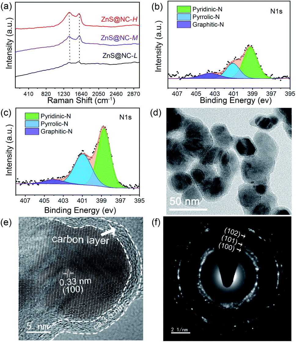 | ||
| Fig. 3 (a) Raman spectra of ZnS@NC-L, ZnS@NC-M, and ZnS@NC-H. XPS spectra of ZnS@NC-M (b) and ZnS@NC-H (c). (d) TEM, (e) HRTEM and (f) SEAD images of ZnS@NC-H. | ||
X-ray photoelectron spectroscopy (XPS) analysis is used to further confirm the above result. As can be seen from Fig. S5(a–c),† Zn, S, C and N elements are turned out to be coexisting in the as-prepared ZnS@NC-L, ZnS@NC-M and ZnS@NC-H. The high-resolution spectrum of Zn 2p (Fig. S5(d–f))† reveals two strong peaks at 1045.33 and 1022.30 eV, which can be ascribed to Zn 2p1/2 and 2p3/2, S 2p (Fig. S5(g–i))† reveals two palpable peaks at 163.44 and 162.22 eV, which can be ascribed to S 2p1/2 and 2p3/2,5 and C 1s (Fig. S5(j–l))† reveals the peaks at 284.8 eV, corresponding to sp2-hydridized C–C/C![[double bond, length as m-dash]](https://www.rsc.org/images/entities/char_e001.gif) C. The weight ratio of nitrogen to carbon in ZnS@NC-L, ZnS@NC-M and ZnS@NC-H surface is 0.029, 0.049 and 0.088, respectively, which verifies that high temperature brings more defect-carbon. Besides, three types of nitrogen atoms are detected, namely, pyridinic-N, pyrrolic-N and graphitic-N atoms, corresponding to locations of binding energy at 398.3, 400.9 and 403.9 eV,53 respectively, as shown in Fig. 3(b, c), S6† and Table 2. It is worth noting that the percentage of graphitic-N decreases with increasing temperature, suggesting that the total amount of pyridinic-N and pyrrolic-N that can effectively enhance the electrochemical performance of electrode materials are increasing.54
C. The weight ratio of nitrogen to carbon in ZnS@NC-L, ZnS@NC-M and ZnS@NC-H surface is 0.029, 0.049 and 0.088, respectively, which verifies that high temperature brings more defect-carbon. Besides, three types of nitrogen atoms are detected, namely, pyridinic-N, pyrrolic-N and graphitic-N atoms, corresponding to locations of binding energy at 398.3, 400.9 and 403.9 eV,53 respectively, as shown in Fig. 3(b, c), S6† and Table 2. It is worth noting that the percentage of graphitic-N decreases with increasing temperature, suggesting that the total amount of pyridinic-N and pyrrolic-N that can effectively enhance the electrochemical performance of electrode materials are increasing.54
| Sample | Pyridinic-N [wt%] | Pyrrolic-N [wt%] | Graphitic-N [wt%] |
|---|---|---|---|
| ZnS@NC-L | 51.84 | 24.83 | 23.3 |
| ZnS@NC-M | 58.94 | 27.66 | 13.4 |
| ZnS@NC-H | 55.07 | 38.87 | 6.04 |
Furthermore, TEM and HRTEM images indicate that ZnS particles are uniformly coated with carbon layer of ca. 3.5 nm (Fig. 3(d and e)). The lattice fringes interlayer distance of 0.33 nm agrees well with the d-spacing of (100) planes of wurtzite ZnS. And the (100), (101), (102) planes of selected area electron diffraction (SAED) image in Fig. 3(f) is well-indexed as pure Würtzite phase ZnS.
Similarly, Würtzite ZnS is also obtained by vacuum pyrolysis at 400 and 800 °C (Fig. S7; preparation information can be found in ESI†), but H is detected by elemental analysis when the temperature of vacuum pyrolysis is 400 °C, which may come from undecomposed organic amines. Higher carbon and nitrogen contents can be obtained at higher temperatures (Table 1). Thus, the conversion process of ZnS(ba) to ZnS@NC can be deducted in Scheme 1. When the temperature is between 200 and 400 °C, ZnS(ba) is decomposing and organic amines escape while the ZnS nanomaterials are formed. Similar phenomena were also observed for other ZnS-amine materials.29,30,42,55,56 Due to the sealing and vacuum buffering effect, organic amines are trapped in the quartz tube and fill the surface of ZnS. When the temperature is higher than 400 °C, part of the organic amines on the surface of ZnS gradually crack into N-doped carbon films and then wrap on the surface of nano-ZnS. Temperature control is the key to the induction of carbon, nitrogen component and the structure of the carbon network in the sealed system: (i) higher temperatures will promote carbonization of the organic components leading to the rising of the content of C and N; (ii) with a higher temperature, defect carbon increase; (iii) compared to graphitic-N, pyridinic-N and pyrrolic-N are easier to form at high temperatures.
 | ||
| Scheme 1 Illustration of the transformation process of ZnS(ba) to different ZnS@NC composites through temperature control. | ||
To confirm the potential of the vacuum pyrolysis in the efficient transformation of ZnS-amine materials to ZnS@carbon materials, a series of ZnS-amine materials (ZnS(ha), ZnS(en)0.5 and ZnS(pda)0.5) are synthesized by the reflux method with high yield. As shown in Fig. 4(a–c), the obtained Exp-ZnS(ha), Exp-ZnS(en)0.5 and Exp-ZnS(pda)0.5 are of high purity, which is confirmed by TG (Fig. S8†). It further verifies that the reflux method is an efficient way towards the large-scale synthesis of ZnS-amine hybrids. Subsequently, these three materials were adopted to the vacuum pyrolysis at the pyrolysis temperature of 700 °C. The ZnS@NC composites are obtained from the pyrolysis of Exp-ZnS(ha), Exp-ZnS(en)0.5 and Exp-ZnS(pda)0.5, in which the contents of carbon and nitrogen are investigated by EA (Fig. 4(a–c) and Table 3). At the same pyrolysis temperature, carbon and nitrogen content of ZnS@NC depends on the type of the organic amine of the ZnS-amine precursors. For instance, since the alkyl chain of n-hexylamine is longer than that of n-butylamine, the ZnS@NC-1 with higher carbon or nitrogen content can be obtained from ZnS(ha) with respect to ZnS@NC-H from ZnS(ba). Further, TEM images verify that zinc sulfide via vacuum pyrolysis from ZnS(ha) and ZnS(pda)0.5 was tightly coated with carbon layer, and the carbon layer was thicker in the case of ZnS(ha), which is well consistent with the results of EA (Fig. 4(c–g) and Table 3).
 | ||
| Fig. 4 (a) XRD patterns of Rep-ZnS(ha),42 Exp-ZnS(ha), ZnS@NC-1; (b) XRD patterns of Rep-ZnS(en)0.5,43 Exp-ZnS(en)0.5, ZnS@NC-2; (c) XRD patterns of Rep-ZnS(pda)0.5,44 Exp-ZnS(pda)0.5, ZnS@NC-1. TEM images of ZnS@NC-1 (d, e) and ZnS@NC-3 (f, g) via the vacuum pyrolysis route. | ||
| Sample | Precursor | C wt% | N wt% | H wt% |
|---|---|---|---|---|
| ZnS@NC-1 | ZnS(ha) | 21.62 | 3.05 | <0.3 |
| ZnS@NC-2 | ZnS(en)0.5 | 5.31 | 1.4 | 0.33 |
| ZnS@NC-3 | ZnS(pda)0.5 | 7.32 | 2.96 | <0.3 |
In a word, the above results indicate the universality of this method for preparing ZnS@NC nanocomposites. What's more, a comparison of the current synthetic strategies of ZnS/NC nanocomposites is presented in Table S2.† Some of them are based on additional carbon and nitrogen source,5–7,9,57 which may suffer from ponderous synthetic procedures, while some of them are limited to expensive nitrogen-rich MOF raw materials when selecting heat treatment of an inert atmosphere,21,26,58 and sometimes further sulfuration is needed.26 Although the vacuum pyrolysis has been successfully applied to synthesize ZnS quantum dots@multilayered N-doped carbon matrix by using the nitrogen-rich MOF as the precursor, the subsequent sulfuration is indispensable.8 By contrast, in this work we use the vacuum pyrolysis route to convert ZnS-amine hybrids to ZnS@NC via a one-pot pyrolysis.
The obtained ZnS@NC composites are then evaluated as LIBs anode materials to exploit their electrochemistry application. All of the electrochemical impedance spectra (EIS) are composed of a depressed semicircle in the high frequency region (interface resistance), a semicircle in the middle to high frequency region (charge-transfer resistance), and an oblique line in the low-frequency domain (semi-infinite Warburg diffusion resistance) (Fig. S9†). The Nyquist plots show that the semicircles of ZnS@NC-M and ZnS@NC-H in the middle to high frequency are much smaller than that of ZnS@NC-L, illustrating the charge transfer resistance (Rct) decreases with the increasing of nitrogen doped carbon content. In Fig. 5(a–c), the ZnS@NC-L, ZnS@NC-M and ZnS@NC-H electrode deliver an initial discharge capacity of 1250, 1234 and 949 mA h g−1 at 0.1 A g−1, respectively. This may be due to the inevitable increase in low-capacity and low-active components when increasing the carbon component to improve conductivity. Similar results can be found in FeS/carbon fibers anodes.59 But the important role to achieve high reversible capacity of N-doped carbon materials gradually appears after the second cycle. Fig. 5(d) shows that a great cycling stability at a current density of 0.1 A g−1 between 0.05 and 3.0 V is observed for ZnS@NC-M and ZnS@NC-H while fast decay is found in ZnS@NC-L. With activation of N-doped carbon materials, ZnS@NC-M and ZnS@NC-H exhibit discharge capacities of 823 and 800 mA h g−1, respectively, after 200 cycles. By contrast, without carbon coating, bare ZnS show an extremely low discharge capacity of 155 mA h g−1 (Fig. S10†). Analogously, ZnS@NC-L with slight amount of N-doped carbon cannot effectively exert its lithium storage performance. High power densities in LIBs usually correlate with good rate performance. Fig. 5(e) plots the rate performance of ZnS@NC materials. It depicts reversible capacities over ZnS@NC-H of ca. 770, 702, 610, 536, 452 and 304 mA h g−1 at a current density of 0.1, 0.2, 0.5, 1.0, 2.0, and 5.0 A g−1, respectively. Even at extremely high current density of 10 A g−1, ZnS@NC-H still maintains a reversible capacity of 200 mA h g−1. But in the case of less N-doped carbon, the capacity decays significantly with the increase of current density from 0.1 to 10 A g−1, especially for sample ZnS@NC-L. Therefore, increasing a certain amount of N-doped carbon of the wrapping layer may be beneficial for ZnS electrodes to achieving the ability of fast charging and discharging during cycling at high current densities.
 | ||
| Fig. 5 Galvanostatic charge–discharge profiles at a current density of 0.1 A g−1 of ZnS@NC-L (a), ZnS@NC-M (b), ZnS@NC-H (c). (d) Long cycling performances at a current density of 0.1 A g−1, (e) rate performances of ZnS@NC-L, ZnS@NC-M and ZnS@NC-H. | ||
Cyclic voltammogram technology is used to explore the electrochemical reactions. Fig. 6(a) shows the CV curves of initial three cycles for the ZnS@NC-H at 0.05–3 V vs. Li+/Li with the scan rate of 0.2 mV s−1. In the first cathodic scanning cycle, a broad peak at around 0.5 V belongs to the reaction of ZnS to Zn (or LixZn) and formation of solid electrolyte interphase film on the electrode surface which cause partial capacity consumption.60 During the anodic scanning cycle, three faint peaks between 0.3–0.7 V are related to the dealloying reaction of lithium-zinc alloy showing a multistep delithiation reaction.60–62 And the strong peak at ca. 1.4 V can be ascribed to regenerated ZnS from Zn.60,63 The reduction and oxidation peaks are high coincident after the second cycle. However, in the case of trace coating, great difference can be found in bare ZnS. It is when reproducing ZnS that they exhibit extremely poor cycle stabilities (Fig. S11†).
 | ||
| Fig. 6 Electric properties of ZnS@NC-H. (a) Cyclic voltammogram curves of initial three cycles at a scan rate of 0.2 mV s−1 between 0.05 and 3.0 V vs. Li/Li+. (b) CV curves at different scan rates of 0.2, 0.3, 0.5, 1.0, 1.5, 2.0 mV s−1. (c) b-Value analysis based on the relationship between the peak currents and the scan rates. (d) Normalized contribution ratios of pseudocapacitance (in color) and diffusion-controlled (in gray) capacities at different scan rates. | ||
To further gain the reason for the outstanding rate performance of ZnS@NC-H anode material, the CV curves with different scan rates range from 0.2 to 2.0 mV s−1 between 0.05 and 3 V are shown in Fig. 6(b). With increasing scan rate, a slightly positive shift in the anodic peaks is caused by the polarization effect during the cycling process.64 The linear change of peak current implies the existence of capacitive control. Pseudocapacitance is an important parameter to quantify the electrochemical kinetics. Diffusion behavior and pseudo-capacitance behavior can be judged through different scan rate (v) and different currents (i) based on formulas (1) and (2).65,66
| i = avb | (1) |
|
logi = blogv + loga
| (2) |
Essentially, b = 1 means that the contribution is completely capacitive, b = 0.5 represents a fully diffusion-controlled contribution, and 0.5 < b < 1 implies the capacity comes from the capacitive and diffusion-controlled contributions. In current experiments, the b value of peak I and peak II can be fitted to be 0.78 and 0.65, respectively, as shown in Fig. 6(c), indicating that the ZnS@NC-H electrode exists pseudocapacitance behavior during charging and discharging, leading to high-rate performance.67
To distinguish its contribution, the capacitive and diffusion process are able to be quantified at specific scan rate by formula (3).68
| i(v) = k1v + k2v1/2 | (3) |
Conclusions
In summary, we have effectively synthesized the ZnS(ba) material on a large scale by the reflux method. The materials of ZnS coated with N-doped carbon in diverse contents are created from ZnS(ba) hybrids through a vacuum pyrolysis route at different pyrolysis temperatures. The detailed conversion process is deducted. Various ZnS-amine materials of ZnS(ha), ZnS(en)0.5 and ZnS(pda)0.5 are synthesized to confirm the efficient transformation of ZnS-amine hybrid to ZnS@NC by the vacuum pyrolysis route. Besides, the synthesized ZnS@NC-H LIBs anode material exhibits an outstanding cycling stability and high rate capability. It can achieve a high reversible capacity of 800 mA h g−1 at the current of 0.1 A g−1 after 200 cycle, and keep a high capacity of 200 mA h g−1 even at a rate of 2.0 A g−1. The obtained ZnS@NC-H material emerges remarkably pseudo-capacitance characteristics.Author contributions
Wen-Hua Liao: data curation, validation, formal analysis, investigation, writing original draft, software. Qian-Qian Hu: writing-reviewing and editing, funding acquisition, supervision. Min Cheng: validation, review. Xiao-Hui Wu: funding acquisition, resources, review. Guang-Hao Zhan: validation, review. Rui-Bo Yan: validation, review. Jian-Rong Li: conceptualization, methodology, funding acquisition, resources, visualization, supervision. Xiao-Ying Huang: conceptualization, writing-reviewing and editing, funding acquisition, resources, visualization, supervision, project administration.Conflicts of interest
There are no conflicts to declare.Acknowledgements
This work is financially supported by the National Nature Science Foundation of China (No. 21905279) and the Natural Science Foundation of Fujian Province (2020J01118) for financial supports.Notes and references
- W.-T. Yao and S.-H. Yu, Synthesis of Semiconducting Functional Materials in Solution: From II–VI Semiconductor to Inorganic–Organic Hybrid Semiconductor Nanomaterials, Adv. Funct. Mater., 2008, 18, 3357–3366 CrossRef CAS.
- M. Bredol and M. Kaczmarek, Potential of nano-ZnS as electrocatalyst, J. Phys. Chem. A, 2010, 114, 3950–3955 CrossRef CAS PubMed.
- Q.-C. Cao, X.-B. Ding, F. Li, Y.-H. Qin and C. Wang, Zinc, sulfur and nitrogen co-doped carbon from sodium chloride/zinc chloride-assisted pyrolysis of thiourea/sucrose for highly efficient oxygen reduction reaction in both acidic and alkaline media, J. Colloid Interface Sci., 2020, 576, 139–146 CrossRef CAS PubMed.
- L. Hu, Z. Wei, F. Yu, H. Yuan, M. Liu, G. Wang, B. Peng, B. Dai and J. Ma, Defective ZnS nanoparticles anchored in situ on N-doped carbon as a superior oxygen reduction reaction catalyst, J. Energy Chem., 2019, 39, 152–159 CrossRef.
- J. Li, L. Wang, L. Li, C. Lv, I. V. Zatovsky and W. Han, Metal Sulfides@Carbon Microfiber Networks for Boosting Lithium Ion/Sodium Ion Storage via a General Metal-Aspergillus niger Bioleaching Strategy, ACS Appl. Mater. Interfaces, 2019, 11, 8072–8080 CrossRef CAS PubMed.
- X. Ma, X. Xiong, P. Zou, W. Liu, F. Wang, L. Liang, Y. Liu, C. Yuan and Z. Lin, General and Scalable Fabrication of Core–Shell Metal Sulfides@C Anchored on 3D N-Doped Foam toward Flexible Sodium Ion Batteries, Small, 2019, 15, 1903259 CrossRef CAS PubMed.
- J. Zhu, Z. Chen, L. Jia, Y. Lu, X. Wei, X. Wang, W. D. Wu, N. Han, Y. Li and Z. Wu, Solvent-free nanocasting toward universal synthesis of ordered mesoporous transition metal sulfide@N-doped carbon composites for electrochemical applications, Nano Res., 2019, 12, 2250–2258 CrossRef CAS.
- D. Fang, S. Chen, X. Wang, Y. Bando, D. Golberg and S. Zhang, ZnS quantum dots@multilayered carbon: geological-plate-movement-inspired design for high-energy Li-ion batteries, J. Mater. Chem. A, 2018, 6, 8358–8365 RSC.
- W. Ji, L. Hu, X. Hu, Y. Ding and Z. Wen, Nitrogen-doped carbon coating mesoporous ZnS nanospheres as high-performance anode material of sodium-ion batteries, Mater. Today Commun., 2019, 19, 396–401 CrossRef CAS.
- X. Wei, H. Yuan, H. Wang, R. Jiang, J. Lan, Y. Yu and X. Yang, The metal–organic framework mediated synthesis of bell string-like hollow ZnS–C nanofibers to enhance sodium storage performance, Mater. Chem. Front., 2021, 5, 4712–4724 RSC.
- J. Yoon, I. T. Kim, J. Bae and J. Hur, High-performance ZnS@graphite composites prepared through scalable high-energy ball milling as novel anodes in lithium-ion batteries, J. Ind. Eng. Chem., 2019, 76, 258–267 CrossRef CAS.
- H. Huang, H. Yu, L. Zhou, E. Gu and D. Jiang, in Optoelectronic Materials, ed. Y. M. Huang, 2010, vol. 663–665, pp. 894–897 Search PubMed.
- H. Hu, X. Wang, F. Liu, J. Wang and C. Xu, Rapid microwave-assisted synthesis of graphene nanosheets-zinc sulfide nanocomposites: optical and photocatalytic properties, Synth. Met., 2011, 161, 404–410 CrossRef CAS.
- L. Xue, C. Shen, M. Zheng, H. Lu, N. Li, G. Ji, L. Pan and J. Cao, Hydrothermal synthesis of graphene-ZnS quantum dot nanocomposites, Mater. Lett., 2011, 65, 198–200 CrossRef CAS.
- S. K. Mishra, A. K. Srivastava, D. Kumar, A. M. Biradar and Rajesh, Microstructural and electrochemical impedance characterization of bio-functionalized ultrafine ZnS nanocrystals-reduced graphene oxide hybrid for immunosensor applications, Nanoscale, 2013, 5, 10494–10503 RSC.
- Y. Tang, J. Tian, T. Malkoske, W. Le and B. Chen, Facile ultrasonic synthesis of novel zinc sulfide/carbon nanotube coaxial nanocables for enhanced photodegradation of methyl orange, J. Mater. Sci., 2017, 52, 1581–1589 CrossRef CAS.
- L. Zhai, Z. Wei, Z. Yang and X. Ni, Polymerization initiated by ZnS nanocrystals anchored on carbon nanotubes, Mater. Lett., 2010, 64, 531–533 CrossRef CAS.
- A. Azodi, A. M. Arabi and M. S. Afarani, Surface modification of carbon nanotubes for the synthesis of CNTs/ZnS quantum dot composites via electrophoretic deposition route, Mater. Res. Express, 2019, 6, 125021 CrossRef CAS.
- J. B. Li, D. Yan, X. J. Zhang, S. J. Hou, T. Lu, Y. F. Yao and L. K. Pan, ZnS nanoparticles decorated on nitrogen-doped porous carbon polyhedra: a promising anode material for lithium-ion and sodium-ion batteries, J. Mater. Chem. A, 2017, 5, 20428–20438 RSC.
- Y. Jing, H. Yin, Y. Zhang and B. Yu, MOF-derived Zn, S, and P co-doped nitrogen-enriched carbon as an efficient electrocatalyst for hydrogen evolution reaction, Int. J. Hydrogen Energy, 2020, 45, 19174–19180 CrossRef CAS.
- X. Lin, B. Liu, H. Huang, C. Shi, Y. Liu and Z. Kang, One-step synthesis of ZnS-N/C nanocomposites derived from Zn-based chiral metal–organic frameworks with highly efficient photocatalytic activity for the selective oxidation of cis-cyclooctene, Inorg. Chem. Front., 2018, 5, 723–731 RSC.
- H. Ding, H. C. Huang, X. K. Zhang, L. Xie, J. Q. Fan, T. Jiang, D. Shi, N. Ma and F. C. Tsai, Zinc Sulfide Decorated on Nitrogen-Doped Carbon Derived from Metal–Organic Framework Composites for Highly Reversible Lithium-Ion Battery Anode, ChemElectroChem, 2019, 6, 5617–5626 CrossRef CAS.
- J. Li, Y. Fu, X. Shi, Z. Xu and Z. Zhang, Urchinlike ZnS Microspheres Decorated with Nitrogen-Doped Carbon: A Superior Anode Material for Lithium and Sodium Storage, Chem.–Eur. J., 2017, 23, 157–166 CrossRef CAS PubMed.
- J. Pan, S. Song, J. Li, F. Wang, X. Ge, S. Yao, X. Wang and H. Zhang, Solid ion transition route to 3D S–N-codoped hollow carbon nanosphere/graphene aerogel as a metal-free handheld nanocatalyst for organic reactions, Nano Res., 2017, 10, 3486–3495 CrossRef CAS.
- L. K. Sarpong, M. Bredol, M. Schoenhoff, A. Wegrzynowicz, K. Jenewein and H. Uphoff, One-pot synthesis of carbon nanotube/zinc sulfide heterostructures: characterization and effect of electrostatic interaction on the optical properties, Opt. Mater., 2018, 86, 398–407 CrossRef CAS.
- Z. B. Zhai, K. J. Huang, X. Wu, H. Hu, Y. Xu and R. M. Chai, Metal–organic framework derived small sized metal sulfide nanoparticles anchored on N-doped carbon plates for high-capacity energy storage, Dalton Trans., 2019, 48, 4712–4718 RSC.
- J. Zhou, Recent Progress on 2D Group II–VI Binary Chalcogenides ZnX and CdX (X = S, Se, Te): From a Theoretical Perspective, Adv. Theory Simul., 2019, 2, 1900061 CrossRef.
- C. Li, X. G. Yang, B. J. Yang, Y. Yan and Y. T. Qian, Growth of microtubular complexes as precursors to synthesize nanocrystalline ZnS and CdS, J. Cryst. Growth, 2006, 291, 45–51 CrossRef CAS.
- Y. H. Ni, X. F. Cao, G. Z. Hu, Z. S. Yang, X. W. Wei, Y. H. Chen and J. Xu, Preparation, conversion, and comparison of the photocatalytic and electrochemical properties of ZnS(en)0.5, ZnS, and ZnO, Cryst. Growth Des., 2007, 7, 280–285 CrossRef CAS.
- J. S. Jang, C. J. Yu, S. H. Choi, S. M. Ji, E. S. Kim and J. S. Lee, Topotactic synthesis of mesoporous ZnS and ZnO nanoplates and their photocatalytic activity, J. Catal., 2008, 254, 144–155 CrossRef CAS.
- G. Zhu, J. Yang, C. Bao, X. Zhang, Z. Ji, S. Wu and X. Shen, Organic–inorganic hybrid ZnS(butylamine) nanosheets and their transformation to porous ZnS, J. Colloid Interface Sci., 2016, 468, 136–144 CrossRef CAS PubMed.
- S. H. Yu and M. Yoshimura, Shape and phase control of ZnS nanocrystals: template fabrication of wurtzite ZnS single-crystal nanosheets and ZnO flake-like dendrites from a lamellar molecular precursor ZnS-(NH2CH2CH2NH2)0.5, Adv. Mater., 2002, 14, 296–300 CrossRef CAS.
- S.-H. Yu, J. Yang, Y.-T. Qian and M. Yoshimura, Optical properties of ZnS nanosheets, ZnO dendrites, and their lamellar precursor ZnS·(NH2CH2CH2NH2)0.5, Chem. Phys. Lett., 2002, 361, 362–366 CrossRef CAS.
- X. Chen, H. Xu, N. Xu, F. Zhao, W. Lin, G. Lin, Y. Fu, Z. Huang, H. Wang and M. Wu, Kinetically controlled synthesis of wurtzite ZnS nanorods through mild thermolysis of a covalent organic–inorganic network, Inorg. Chem., 2003, 42, 3100–3106 CrossRef CAS PubMed.
- W. T. Yao, S. H. Yu and Q. S. Wu, From mesostructured wurtzite ZnS-nanowire/amine nanocomposites to ZnS nanowires exhibiting quantum size effects: a mild-solution chemistry approach, Adv. Funct. Mater., 2007, 17, 623–631 CrossRef CAS.
- G. Xi, C. Wang, X. Wang, Q. Zhang and H. Xiao, From ZnS·en0.5Nanosheets to Wurtzite ZnS Nanorods under Solvothermal Conditions, J. Phys. Chem. C, 2008, 112, 1946–1952 CrossRef CAS.
- T. Ma, F. Zhou, T. W. Zhang, H. B. Yao, T. Y. Su, Z. L. Yu, Y. Li, L. L. Lu and S. H. Yu, Large-Scale Syntheses of Zinc Sulfide(Diethylenetriamine)0.5 Hybrids as Precursors for Sulfur Nanocomposite Cathodes, Angew. Chem., Int. Ed., 2017, 56, 11836–11840 CrossRef CAS PubMed.
- H. Y. Lu, X. H. Zhang, F. Wan, D. S. Liu, C. Y. Fan, H. M. Xu, G. Wang and X. L. Wu, Flexible P-Doped Carbon Cloth: Vacuum-Sealed Preparation and Enhanced Na-Storage Properties as Binder-Free Anode for Sodium Ion Batteries, ACS Appl. Mater. Interfaces, 2017, 9, 12518–12527 CrossRef CAS PubMed.
- P. Tian, J. Zang, S. Jia, Y. Zhang, H. Gao, S. Zhou, W. Wang, H. Xu and Y. Wang, Preparation of S/N co-doped graphene through a self-generated high gas pressure for high rate supercapacitor, Appl. Surf. Sci., 2018, 456, 781–788 CrossRef CAS.
- X. Cheng, D. Li, F. Liu, R. Xu and Y. Yu, Binding Nanosized Cobalt Chalcogenides in B,N-Codoped Graphene for Enhanced Sodium Storage, Small Methods, 2018, 3, 1800170 CrossRef.
- T. C. King, P. D. Matthews, J. P. Holgado, D. A. Jefferson, R. M. Lambert, A. Alavi and D. S. Wright, A single-source route to bulk samples of C3N and the co-evolution of graphitic carbon microspheres, Carbon, 2013, 64, 6–10 CrossRef CAS.
- X. Huang and J. Li, From single to multiple atomic layers: a unique approach to the systematic tuning of structures and properties of inorganic–organic hybrid nanostructured semiconductors, J. Am. Chem. Soc., 2007, 129, 3157–3162 CrossRef CAS PubMed.
- X. Ouyang, T. Y. Tsai, D. H. Chen, Q. J. Huang, W. H. Cheng and A. Clearfield, Ab initio structure study from in-house powder diffraction of a novel ZnS(en)0.5 structure with layered wurtzite ZnS fragment, Chem. Commun., 2003, 886–887 RSC.
- K. Luberda-Durnas, B. Gawel, M. Los and W. Lasocha, Synthesis and characterization of inorganic–organic ZnS(aminopropane)n composite materials, Cryst. Res. Technol., 2011, 46, 1283–1290 CrossRef CAS.
- Y. Chen, Y. Wang, X. Zhou, Y. Zhao and W. Peng, Defected graphene as effective co-catalyst of CdS for enhanced photocatalytic activities, Environ. Sci. Pollut. Res., 2020, 27, 26810–26816 CrossRef CAS PubMed.
- Y. Jia, L. Zhang, A. Du, G. Gao, J. Chen, X. Yan, C. L. Brown and X. Yao, Defect Graphene as a Trifunctional Catalyst for Electrochemical Reactions, Adv. Mater., 2016, 28, 9532–9538 CrossRef CAS PubMed.
- Y. Jia, L. Zhang, L. Zhuang, H. Liu, X. Yan, X. Wang, J. Liu, J. Wang, Y. Zheng, Z. Xiao, E. Taran, J. Chen, D. Yang, Z. Zhu, S. Wang, L. Dai and X. Yao, Identification of active sites for acidic oxygen reduction on carbon catalysts with and without nitrogen doping, Nat. Catal., 2019, 2, 688–695 CrossRef CAS.
- H. Zhao, C. Sun, Z. Jin, D.-W. Wang, X. Yan, Z. Chen, G. Zhu and X. Yao, Carbon for the oxygen reduction reaction: a defect mechanism, J. Mater. Chem. A, 2015, 3, 11736–11739 RSC.
- Y. Zhao, D. Wu, Y. Chen, Y. Li, X. Fan, F. Zhang, G. Zhang and W. Peng, Thermal removal of partial nitrogen atoms in N-doped graphene for enhanced catalytic oxidation, J. Colloid Interface Sci., 2021, 585, 640–648 CrossRef CAS PubMed.
- J. Zhu, Y. Huang, W. Mei, C. Zhao, C. Zhang, J. Zhang, I. S. Amiinu and S. Mu, Effects of Intrinsic Pentagon Defects on Electrochemical Reactivity of Carbon Nanomaterials, Angew. Chem., Int. Ed., 2019, 58, 3859–3864 CrossRef CAS PubMed.
- S. F. Huang, Z. P. Li, B. Wang, J. J. Zhang, Z. Q. Peng, R. J. Qi, J. Wang and Y. F. Zhao, N-Doping and Defective Nanographitic Domain Coupled Hard Carbon Nanoshells for High Performance Lithium/Sodium Storage, Adv. Funct. Mater., 2018, 28, 1706294 CrossRef.
- D. W. Kim, S. M. Jung, C. Senthil, S. S. Kim, B. K. Ju and H. Y. Jung, Understanding Excess Li Storage beyond LiC6 in Reduced Dimensional Scale Graphene, ACS Nano, 2021, 15, 797–808 CrossRef CAS PubMed.
- H. B. Wang, C. J. Zhang, Z. H. Liu, L. Wang, P. X. Han, H. X. Xu, K. J. Zhang, S. M. Dong, J. H. Yao and G. L. Cui, Nitrogen-doped graphene nanosheets with excellent lithium storage properties, J. Mater. Chem., 2011, 21, 5430–5434 RSC.
- Y. Li, M. H. Chen, B. Liu, Y. Zhang, X. Q. Liang and X. H. Xia, Heteroatom Doping: An Effective Way to Boost Sodium Ion Storage, Adv. Energy Mater., 2020, 10, 2000927 CrossRef CAS.
- A. K. Kole, C. S. Tiwary and P. Kumbhakar, Ethylenediamine assisted synthesis of wurtzite zinc sulphide nanosheets and porous zinc oxide nanostructures: near white light photoluminescence emission and photocatalytic activity under visible light irradiation, CrystEngComm, 2013, 15, 5515–5525 RSC.
- A. Hernandez-Gordillo, F. Tzompantzi and R. Gomez, An efficient ZnS-UV photocatalysts generated in situ from ZnS(en)0.5 hybrid during the H-2 production in methanol–water solution, Int. J. Hydrogen Energy, 2012, 37, 17002–17008 CrossRef CAS.
- M. W. Khan, X. Zuo, Q. Yang, H. Tang, K. M. U. Rehman, M. Wu and G. Li, Quantum dot embedded N-doped functionalized multiwall carbon nanotubes boost the short-circuit current of Ru(II) based dye-sensitized solar cells, Nanoscale, 2020, 12, 1046–1060 RSC.
- C. Guo, Q. Wang, J. He, C. Wu, K. Xie, Y. Liu, W. Zhang, H. Cheng, H. Hu and C. Wang, Rational Design of Unique ZnO/ZnS@N–C Heterostructures for High Performance Lithium-Ion Batteries, J. Phys. Chem. Lett., 2020, 11, 905–912 CrossRef CAS PubMed.
- D. Li, Y. Sun, S. Chen, J. Yao, Y. Zhang, Y. Xia and D. Yang, Highly Porous FeS/Carbon Fibers Derived from Fe-Carrageenan Biomass: High-capacity and Durable Anodes for Sodium-Ion Batteries, ACS Appl. Mater. Interfaces, 2018, 10, 17175–17182 CrossRef CAS PubMed.
- G. Y. Tian, Z. J. Zhao, A. Sarapulova, C. Das, L. H. Zhu, S. Y. Liu, A. Missiul, E. Welter, J. Maibach and S. Dsoke, Understanding the Li-ion storage mechanism in a carbon composited zinc sulfide electrode, J. Mater. Chem. A, 2019, 7, 15640–15653 RSC.
- F. Mueller, D. Geiger, U. Kaiser, S. Passerini and D. Bresser, Elucidating the Impact of Cobalt Doping on the Lithium Storage Mechanism in Conversion/Alloying-Type Zinc Oxide Anodes, ChemElectroChem, 2016, 3, 1311–1319 CrossRef CAS.
- Y. Ma, Y. J. Ma, D. Geiger, U. Kaiser, H. Zhang, G. T. Kim, T. Diemant, R. J. Behm, A. Varzi and S. Passerini, ZnO/ZnFe2O4/N-doped C micro-polyhedrons with hierarchical hollow structure as high-performance anodes for lithium-ion batteries, Nano Energy, 2017, 42, 341–352 CrossRef CAS.
- M. L. Mao, L. Jiang, L. C. Wu, M. Zhang and T. H. Wang, The structure control of ZnS/graphene composites and their excellent properties for lithium-ion batteries, J. Mater. Chem. A, 2015, 3, 13384–13389 RSC.
- Y. Dong, M. Hu, Z. Zhang, J. A. Zapien, X. Wang and J. M. Lee, Hierarchical self-assembled Bi2S3 hollow nanotubes coated with sulfur-doped amorphous carbon as advanced anode materials for lithium ion batteries, Nanoscale, 2018, 10, 13343–13350 RSC.
- D. Chao, C. Zhu, P. Yang, X. Xia, J. Liu, J. Wang, X. Fan, S. V. Savilov, J. Lin, H. J. Fan and Z. X. Shen, Array of nanosheets render ultrafast and high-capacity Na-ion storage by tunable pseudocapacitance, Nat. Commun., 2016, 7, 12122 CrossRef CAS PubMed.
- J. Wang, J. Polleux, J. Lim and B. Dunn, Pseudocapacitive contributions to electrochemical energy storage in TiO2 (anatase) nanoparticles, J. Phys. Chem. C, 2007, 111, 14925–14931 CrossRef CAS.
- K. Zhang, Z. Hu, X. Liu, Z. Tao and J. Chen, FeSe2 Microspheres as a High-Performance Anode Material for Na-Ion Batteries, Adv. Mater., 2015, 27, 3305–3309 CrossRef CAS PubMed.
- Z. Chen, R. Wu, H. Wang, K. H. L. Zhang, Y. Song, F. Wu, F. Fang and D. Sun, Embedding ZnSe nanodots in nitrogen-doped hollow carbon architectures for superior lithium storage, Nano Res., 2018, 11, 966–978 CrossRef CAS.
Footnote |
| † Electronic supplementary information (ESI) available. See DOI: 10.1039/d1ra06427d |
| This journal is © The Royal Society of Chemistry 2021 |