
 Open Access Article
 This Open Access Article is licensed under a Creative Commons Attribution-Non Commercial 3.0 Unported Licence
First-principles based theoretical calculations of atomic structures of hydroxyapatite surfaces and their charge states in contact with aqueous solutions†
T. Saito *a,
T. Yokoia,
A. Nakamuraa and
K. Matsunaga*ab
*a,
T. Yokoia,
A. Nakamuraa and
K. Matsunaga*ab
aDepartment of Materials Physics, Nagoya University, Nagoya 464-8603, Japan. E-mail: t-saito@nagoya-u.jp; kmatsunaga@nagoya-u.jp
bNanostructures Research Laboratory, Japan Fine Ceramics Center, Nagoya 456-8587, Japan
First published on 20th October 2021
Abstract
Surface charge states of biomaterials are often important for the adsorption of cells, proteins, and foreign ions on their surfaces, which should be clarified at the atomic and electronic levels. First-principles calculations were performed to reveal thermodynamically stable surface atomic structures and their charge states in hydroxyapatite (HAp). Effects of aqueous environments on the surface stability were considered using an implicit solvation model. It was found that in an air atmosphere, stoichiometric {0001} and P-rich {10![[1 with combining macron]](https://www.rsc.org/images/entities/char_0031_0304.gif) 0} surfaces are energetically favorable, whereas in an aqueous solution, a Ca-rich {100} surface is the most stable. This difference suggests that preferential surface structures strongly depend on chemical environments with and without aqueous solutions. Their surface potentials at zero charge were calculated to obtain the isoelectric points (pHPZC). pHPZC values for the {0001} surface and the Ca-rich {100} surface were obtained to be 4.8 and 8.7, respectively. This indicates that in an aqueous solution at neutral pH, the {0001} and Ca-rich {100} surfaces are negatively and positively charged, respectively. This trend agrees with experimental data from chromatography and zeta potential measurements. Our methodology based on first-principles calculations enables determining macroscopic charge states of HAp surfaces from atomic and electronic levels.
0} surfaces are energetically favorable, whereas in an aqueous solution, a Ca-rich {100} surface is the most stable. This difference suggests that preferential surface structures strongly depend on chemical environments with and without aqueous solutions. Their surface potentials at zero charge were calculated to obtain the isoelectric points (pHPZC). pHPZC values for the {0001} surface and the Ca-rich {100} surface were obtained to be 4.8 and 8.7, respectively. This indicates that in an aqueous solution at neutral pH, the {0001} and Ca-rich {100} surfaces are negatively and positively charged, respectively. This trend agrees with experimental data from chromatography and zeta potential measurements. Our methodology based on first-principles calculations enables determining macroscopic charge states of HAp surfaces from atomic and electronic levels.
1. Introduction
Hydroxyapatite (HAp, Ca10(PO4)6(OH)2) is a main inorganic compound in human bones and enamels and is thus used in artificial bone grafts and implants. HAp also shows a high affinity for cells, proteins, and amino acids,1–3 meeting a wide range of applications, including chromatography and drug delivery systems.4,5 In such applications, HAp surfaces are considered to have positive or negative charge states depending on surface orientations and their relevant atomic structures and can attract various ions in body fluids and other aqueous solutions (e.g., H+, Ca2+, OH−, and PO43−).6 Surface charge states of HAp can also affect cell adsorption, crystal growth, and dissolution by electrostatically repelling and attracting ions or molecules with the surface charges.7–10 It is thus essential to reveal the physical origin of the emergence of surface charges in HAp, with the goal of designing HAp-based biomaterials with excellent adsorption and bioactive properties.HAp has a hexagonal structure with a space group of P63/m. Since HAp crystals typically have morphologies of hexagonal rods growing along the c axis or thin plates, two major surface planes are formed in large areas. One is the {0001} surface (c plane), and the other is the {100} surface (a(b) plane). According to previous experiments, positively charged lysozymes (LSZs) were more preferentially adsorbed on the {0001} surface than the {100} surface, whereas negatively charged bovine serum albumins (BSAs) showed preference to be adsorbed on the {100} surface.11–15 Therefore, it is believed that {100} and {0001} surfaces are positively and negatively charged, respectively. It was also reported that surface zeta potentials of HAp crystal rods shifted from negative to positive values with increasing areas of the {100} surface.16 In contrast, HAp crystals with a large area of the {0001} surface was found to have more negative zeta potentials than those oriented isotropically.17
In earlier studies with chromatographic measurements, a physical origin of surface charge states in HAp was speculated in terms of possible atomic structures of {100} and {0001} surfaces.5,18–21 These studies indicated that HAp crystals have amphoteric adsorption properties of acidic (negatively charged) and basic (positively charged) proteins. Considering these results, Bernardi proposed that particular Ca and P sites at HAp surfaces can become absorption sites for acidic and basic proteins.18 On the basis of the crystal structure of octacalcium phosphate (Ca8H2(PO4)6·5H2O),22 Kawasaki suggested that the {100} surfaces have vacant sites of OH− ions and thus can serve as positively charged absorption sites, whereas the {0001} surfaces have vacant sites of Ca2+ ions as negatively charged absorption sites.5,20,21
In the last decades, HAp surface structures have been experimentally investigated using scanning electron microscopy (SEM), transmission electron microscopy (TEM), and high-resolution transmission microscopy (HRTEM).17,23,24 Sato et al. observed crystalline–amorphous interfaces of sintered HAp using HRTEM25 and suggested that a nonstoichiometric {100} surface terminated at OH− ions is one of the most stable surface structures. Ospina et al. applied a focal series reconstruction technique to HRTEM images and proposed that the {100} surface is terminated at a nonstoichiometric layer with flatly arranged Ca ions.26 The presence of different surface terminations reported above is also supported by FTIR measurements combined with DFT calculations.27–29 However, direct observations of atomic structures of HAp surfaces were not attained, probably because of difficulties of HAp-surface preparations and electron-beam damages.
In contrast, a number of theoretical calculations treated HAp surfaces in contact with water molecules and showed that two kinds of nonstoichiometric {100} surfaces are energetically favorable.30,31 However, these studies considered the adsorption of a single H2O molecule or a monolayer of H2O molecules and did not explicitly account for the presence of an aqueous solution at the DFT level. It can thus be said that energetically favorable atomic structures of HAp surfaces in contact with aqueous solutions are still poorly understood. As a matter of course, the surface charge states and their physical origin have never been clarified.
In the current work, DFT calculations are performed to reveal thermodynamically favorable atomic structures of HAp surfaces and their charge states in contact with aqueous solutions. To model HAp surfaces in aqueous solutions, an implicit solvation model is employed in combination with DFT calculations. To obtain surface charge states of HAp in aqueous solutions, surface potentials at zero charge are calculated. Isoelectric points for HAp surfaces are finally estimated from their surface potentials to determine their surface charge states at the atomic and electronic levels.
2. Computational procedures
2.1 Electronic structure calculation
DFT calculations were performed with the projector augmented wave (PAW) method implemented in the Vienna Ab initio Simulation Package (VASP).32 The generalized gradient approximation parameterized by Perdew, Burke, and Ernzerhof (GGA-PBE) was used to calculate the exchange-correlation potential.33 Electrons of 3s23p64s2 for Ca, 3s23p3 for P, 2s22p4 for O and 1s1 for H were treated as valence electrons. Wave functions were expanded by plane waves with an energy cutoff of 800 eV, for which surface energies are found to sufficiently converge for both aqueous solution and vacuum. A 2 × 2 × 2 k-point mesh was used for a hexagonal unit cell of HAp. Atomic positions were optimized until atomic forces became less than 0.02 eV Å−1. In these conditions, lattice parameters of the HAp unit cell were calculated to be 9.56 Å and 6.91 Å for the a and c axes, respectively. These values are in good agreement with experimental data, within an error of <1.3%.34 Additionally, the diagonal components of stress tensor became small within 3 × 10⁻² GPa and the others are negligible (<10−7 GPa), suggesting that the current optimization successfully gets rid of internal stresses.An implicit solvation model35,36 based on the Poisson–Boltzmann equation was used to investigate a HAp surface immersed in an aqueous solution. If a solute/solvent system is treated only within DFT calculations, computational costs are very expensive due to a large number of solvent molecules. Alternatively, the implicit solvation model represents solvent molecules as a continuum dielectric, which corresponds to averaged molecular configurations of solvents. This approach greatly reduces computational costs by avoiding explicit consideration of solvent molecules. However, it is theoretically and experimentally suggested that strongly ordered water layers are present on apatite surfaces,37–39 which are expected to decrease the dielectric constant of water near surfaces. Although the current implicit solvation model does not explicitly consider individual water molecules and thereby their ordering at surfaces, it represents the dielectric constant as a function of the electronic charge density of the solute/solvent, as described in the literature.36 This formulation ensures a smooth decrease in the dielectric constant with decreasing distance from the surface. Implicit solvation was described with the default setting for water reported in the literature35,36 (i.e., dielectric constant εb = 78.4, width of dielectric cavity σ = 0.6, cutoff charge density nck = 0.0025 Å−3 and a surface tension parameter of 0.525 meV Å−2). To describe an electronic double-layer region, a Debye length λd = 3.0 Å was used by assuming an aqueous solution containing 1 mol L−1 concentration of monovalent anions and cations at 298 K.
A number of different implicit solvation models are proposed and are used in different DFT-based programs. In order to assess the present methodologies, test calculations with the effective screening medium and the reference interaction site methods (ESM-RISM) implemented in QUANTUM ESPRESSO40 were also performed. It was confirmed that the present results show the same trends in potentials of zero charge and isoelectric points for HAp surfaces. More details can be found in Section S1 in the ESI.†
2.2 Surface structures and slab models
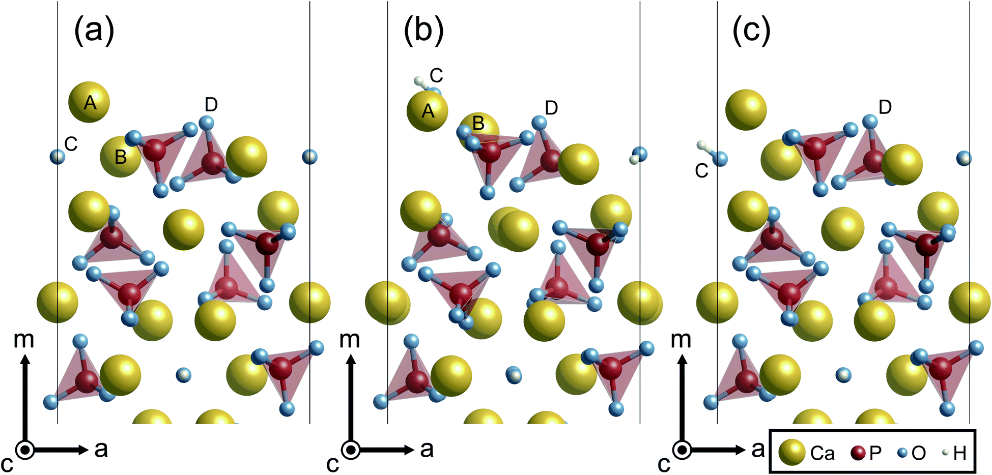
To begin with, surface terminations of HAp are described. Here, {0001}, {100}, and {11![[2 with combining macron]](https://www.rsc.org/images/entities/char_0032_0304.gif) 0} surface planes of hexagonal HAp were considered since HAp crystal grains preferentially form hexagonal rods growing along the c axis. In order to prepare the surface slab models, it is advantageous to consider the stacking sequence of charge-neutral atomic layers. Fig. 1 illustrates atomic layers stacked in directions normal to the surface planes. The directions normal to {100} and {110} planes are conventionally called the m and a axes for hexagonal crystals, respectively, and these notations are also used in the present study.
0} surface planes of hexagonal HAp were considered since HAp crystal grains preferentially form hexagonal rods growing along the c axis. In order to prepare the surface slab models, it is advantageous to consider the stacking sequence of charge-neutral atomic layers. Fig. 1 illustrates atomic layers stacked in directions normal to the surface planes. The directions normal to {100} and {110} planes are conventionally called the m and a axes for hexagonal crystals, respectively, and these notations are also used in the present study.
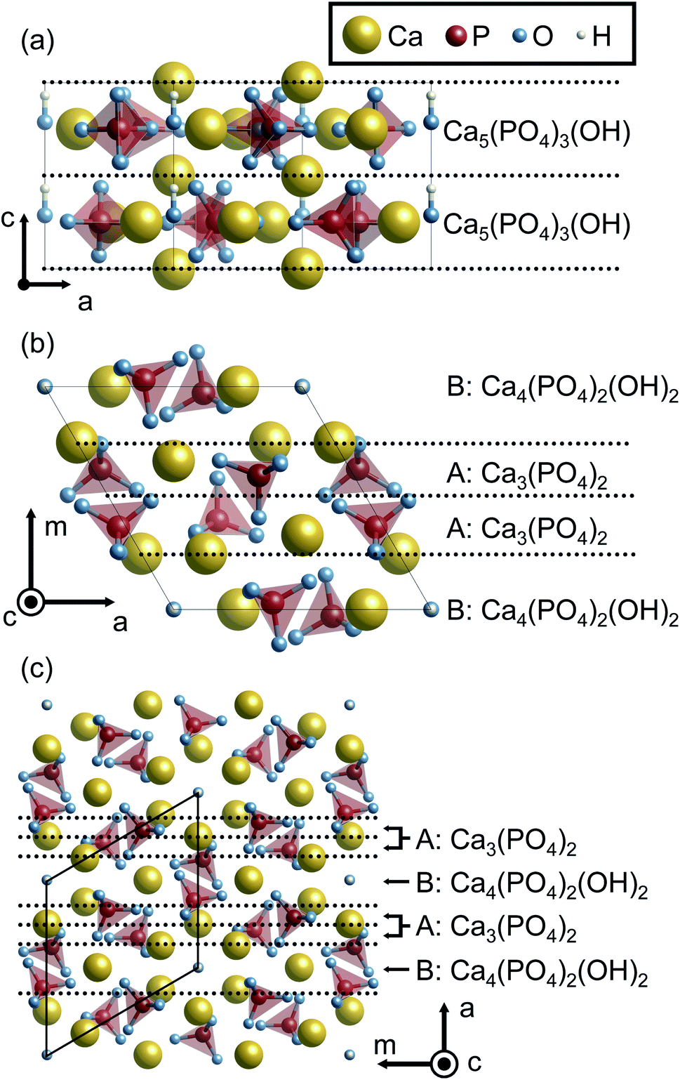 | ||
| Fig. 1 HAp crystal structures viewed along the m and c axes. Stacking sequences of the atomic layers are indicated along the (a) c, (b) m and (c) a axes. The yellow, red, blue, and white balls represent Ca, P, O, and H atoms, respectively. In addition, PO4 groups are represented by tetrahedra. Each layer is separated by the dashed lines. The composition of each layer is also indicated. | ||
Along the c axis, the HAp crystal structure can be described by the stacking of stoichiometric atomic layers Ca5(PO4)3(OH). Therefore, the {0001} surface can always be stoichiometric. However, it should be noted that hexagonal HAp contains hydroxyl groups (OH−) arranged along the c axis. Since it is assumed here that OH− arrangements are not disordered but ordered along the c axis in the present study, two possible {0001} surface terminations of …–OH–OH (P-pole) and …–HO–HO (N-pole) can be generated.
Along the m and a axes, two different layers are alternately stacked (Fig. 1(b) and (c), respectively). One is the Ca3(PO4)2 layer (A layer). This layer has a Ca/P molar ratio of 1.5, and thus is in the P-rich composition (the stoichiometric Ca/P molar ratio of 1.67). The other is the Ca4(PO4)2(OH)2 layer (B layer). This layer has a Ca/P molar ratio of 2.0, and can be called a Ca-rich layer. It is noted that these off-stoichiometric Ca/P layers are charge neutral. As a result, HAp can be described by a stacking sequence of the two layers as …AABAAB… and thus three possible terminations for the surfaces were considered: …AAB (Ca-rich), …ABA (stoichiometric), and …BAA (P-rich).
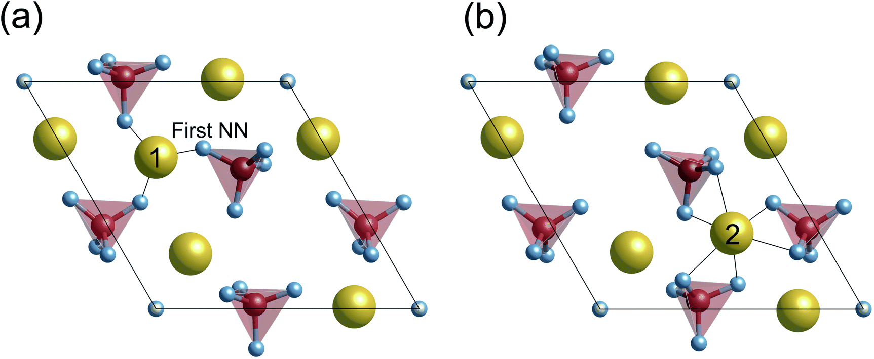
When the surface slabs are generated, it is necessary to consider locations of Ca ions at the boundaries of the atomic layers to keep the surfaces charge-neutral and non-dipolar. Fig. 2 displays atomic configurations around the outermost atomic layers at the {0001}, {100}, and {110} surfaces. As can be seen in Fig. 2(a), the {0001} surface has two outermost Ca sites, denoted as Ca1 and Ca2. However, one of the Ca sites should be vacant due to the charge neutrality of the surface. Additionally, a {0001} surface formation leads to mirror symmetry breaking, and as a result, the Ca1 and Ca2 sites are crystallographically inequivalent. For these reasons, two different atomic configurations at the surface can be considered.
 | ||
| Fig. 2 Unrelaxed atomic structures of (a) stoichiometric {0001}, (b) Ca-rich {100}, (c) P-rich {100}, and (d) stoichiometric {110} viewed parallel to the surface planes. | ||
Similarly, the Ca- and P-rich {100} surfaces contain three outermost Ca sites, one of which should be occupied and vacant, respectively (see Fig. 2(b) and (c)). Three different surface structures for each {100} surface can be obtained, and two different surface structures are possible for the {110} surface. In this study, these different atomic configurations for the surfaces were considered to determine the lowest-energy surface structures.
Based on the abovementioned considerations, the surface slab models were generated. The HAp unit cell was repeated by 1 × 1 × 2, 1 × 2 × 1, and 2 × 2 × 1 for {0001}, {100}, and {110} surface slabs, respectively. Since two surfaces in each slab should be identical and it is desirable that these slabs for different surfaces have similar thicknesses, the stacking sequences of A and B layers were set to be A–A–B–A–A for the P-rich {100}, B–A–A–B–A–A–B for the Ca-rich {100}, and {110} and A–A–B–A–A–B–A–A–B–A–A for the P-rich {110} surfaces. Each slab was separated by a vacuum/solution layer with more than 14 Å thickness. It is noted that the two surfaces introduced in a {0001} slab are crystallographically different due to the directional arrangement of OH− ions along the c axis, and thus N- and P-pole surfaces are formed. The OH− arrangements may cause artificial electric fields through the surface slabs. In order to prevent this, the OH− arrangements were modified to be symmetric with respect to the centers of the surface slabs, i.e., HO–HO–OH–OH or OH–OH–HO–HO. With these OH− configurations, the surface potentials of zero charge (described in Section 2.4) of the two surfaces were separately calculated. To calculate surface energies, the directional arrangement was adopted, as described in Section 2.3.
In order to check the dependences of surface energies and surface potentials on thicknesses of crystal and solution layers, test calculations in the implicit solvation model were performed. It was found that surface energies and surface potentials change by merely 2 × 10⁻³ J m−2 and 2 × 10⁻² V, by increasing the solution layer from 14 Å to 29 Å. Similarly, it was also confirmed that the two quantities are little changed (5 × 10⁻³ J m−2 and 5 × 10⁻² V) by increasing the crystal layer from 12 Å to 29 Å. Dilute concentrations of the solutes within 2 × 10⁻² mol L−1 were also tested with λd = 5.0, 8.0, 10.0, and 20.0 for the Ca-rich {100} surface. The surface energy and surface potential were found to be less sensitive to λd, with differences of 2 × 10⁻³ J m−2 and 3 × 10⁻² V, respectively.
2.3 Surface energies and chemical potentials
Surface energy (ΔEs) is defined as a difference in total energy between a bulk structure (Ebulkt) and a surface slab (Eslabt), as follows:
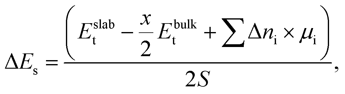 | (1) |
 | (2) |
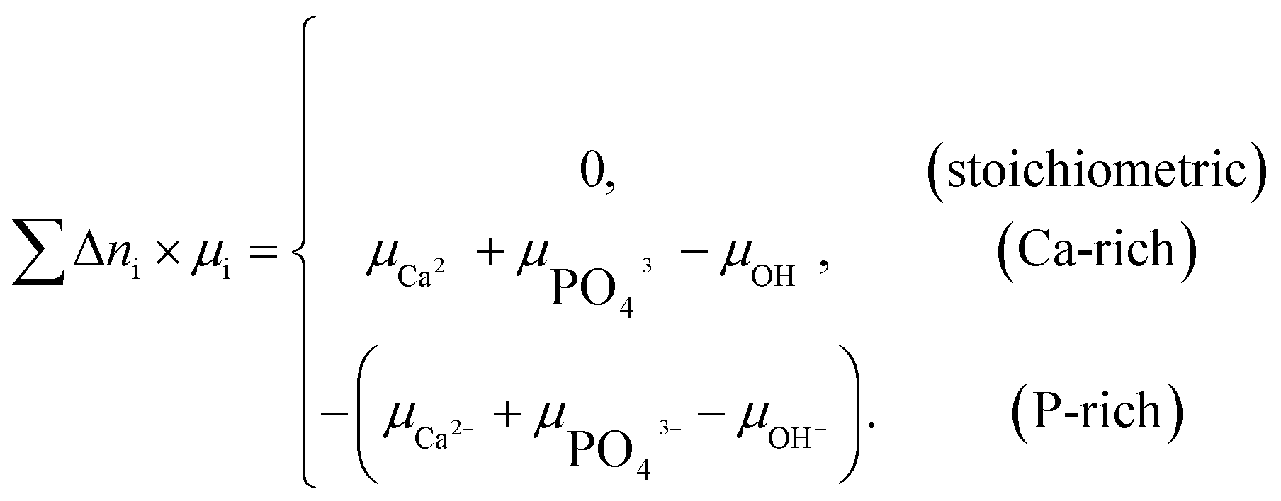
Two chemical equilibrium conditions were used to determine μi: a normal air atmosphere at a given temperature and an aqueous solution at 298 K. In the air atmosphere, HAp was assumed to be in equilibrium with the CaO solid, O2 gas, and H2O gas at a particular temperature T. The partial pressures were set to pO2 = 0.21 atm and pH2O = 1 × 10⁻⁵ atm. The chemical potentials of HAp and CaO were assumed to be equal to their total energies per unit formula obtained from DFT calculations. Chemical potentials for gaseous species are given by 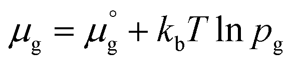 , where
  is a standard chemical potential and kb is the Boltzmann constant.
  at 0 K was calculated from DFT calculations with an isolated molecule in cubic supercells of 15 × 15 × 15 Å3. The temperature dependence of
  was taken from the thermodynamic data.68
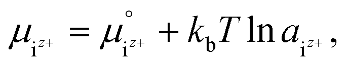
It was assumed that the aqueous solution considered here is saturated with respect to HAp and that Ca2+, PO43−, HPO42−, H2PO4−, H3PO4, OH−, and H+ are dissolved in the aqueous solution. Their chemical potentials are given by
 | (3) |
 is the activity, and
  is the standard chemical potential of an ionic species iz+ in the aqueous solution. The values of
  were determined from DFT calculations and experimental thermodynamic data. As an example, for Ca2+,
  is provided by the reaction of Ca(s) + 2H+(aq.) = Ca2+(aq.) + H2(g). The reaction provides the standard Gibbs energy of formation for Ca2+(aq.)
  . The value was obtained from the thermodynamic data.69 Finally,
  is obtained by
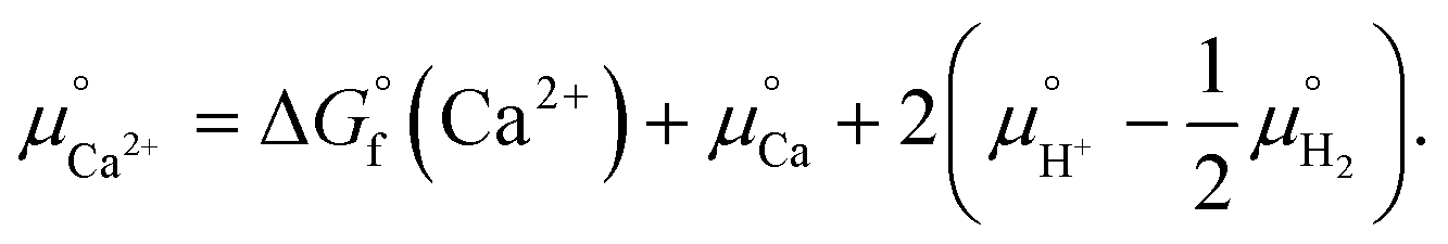 | (4) |
Notice that it is not necessary to evaluate the standard chemical potential of proton  because
  should be automatically canceled in eqn (2) due to the charge neutrality requirement.
In eqn (3),  is the product of the ionic concentration and the activity coefficient. Since HAp is hard to dissolve and thus its saturated solution can be considered as being dilute and ideal, the activity coefficients were assumed to be 1. Concentrations of ionic species were calculated from experimental data of the solubility product of HAp,41 ionic products of water, and three phosphoric acids (H3PO4 = H+ + H2PO4−, H2PO4− = H+ + HPO42−, HPO42− = H+ + PO43−). The Ca/P molar ratio in the solution was considered to be the same as that of HAp. Ionic concentrations thus obtained as a function of pH are shown in Fig. S1 in the ESI.† Further details for the derivation of chemical potentials can also be seen elsewhere.42–44
2.4 Surface potentials of zero charge and isoelectric points
A potential of zero charge φPZC is generally defined as an electrostatic potential of a neutral electrode at which an electrode/electrolyte interface exhibits a net zero charge. This is experimentally determined with respect to a reference potential, and a conventional choice of the reference in electrochemistry is the standard hydrogen electrode (SHE). In contrast, an electrostatic potential of the bulk electrolyte is selected for reference in computational modeling with the implicit solvation model, which was also used in the present study.35φPZC values for HAp surfaces with different orientations and atomic structures were evaluated using the surface slab models with the implicit solvation model. In principle, since a surface potential is defined as an electrostatic potential of a point charge at the surface with respect to that of a reference, φPZC for the surface slabs can be obtained from their Fermi energies Ef. When an electrostatic potential in the bulk electrolyte Eref (the implicit aqueous solution in this study) is taken as a reference, φPZC can be obtained in the following manner.
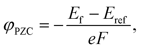 | (5) |
In general, it is considered that when oxide surfaces are immersed in aqueous solutions, hydration occurs, and the surfaces are terminated with hydroxyl groups in the neutral state. The surface termination can be simply denoted as –MOH, where M means a cation on the surface. At a particular low pH condition, protons are enriched in the electrolyte, and the surface hydroxyl groups can interact with them to form –MOH2+. Then, the surface can take a positive charge. Inversely, at a larger pH condition, protons at the surface –MOH groups are dissociated and form H2O with enriched OH− groups in the aqueous solution so that the surface termination can be negative as –MO−. Therefore, there is a pH of zero charge, which is called the isoelectric point pHPZC.
As stated above, φPZC and pHPZC indicates surface charge states in different ways. pHPZC expresses a potential of zero charge φPZC in terms of pH. In this regard, McCafferty introduced the theoretical relationship between pHPZC and φPZC on the basis of electrochemistry, and showed that φPZC is linearly proportional to pHPZC for oxides as follows:45
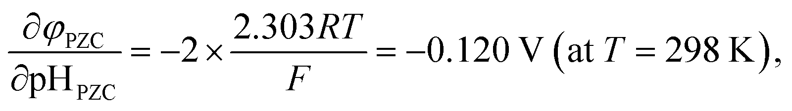 | (6) |
| Material | Surface plane | Experimental pHPZC (average) |
|---|---|---|
| MgO | {001}, {110} | 12–12.5 (12.3) |
| SiO2 | {0001}, {100}, {101}, {011} |
2.0–3.0 (2.5) |
| α-Al2O3 | {0001}, {100}, {110}, {012} |
8.2–9.2 (8.7) |
| CaCO3 | {100}, {110}, {104} |
5.4 |
3. Results and discussion
3.1 Surface energies in air atmosphere and aqueous solution
Fig. 3 shows the surface energies of HAp (ΔEs) obtained under assumptions of the air atmosphere and the saturated aqueous solution. As stated in Section 2.2, the stoichiometric {0001} surface slabs have N- and P-pole surfaces. Because each of the {0001} surface slabs has both N- and P-pole surfaces, their averaged value of ΔEs is represented in Fig. 3. In the air atmosphere (Fig. 3(a)), the stoichiometric {0001} surface has ΔEs of 0.58 J m−2, which is also the smallest of all below about 800 K. Among the lateral surfaces of {100} and {110}, the P-rich {100} surface is most stable over the entire temperature range. This indicates that HAp crystal grains are surrounded by the stoichiometric {0001} and the P-rich {100} surfaces when they are produced in the air atmosphere.
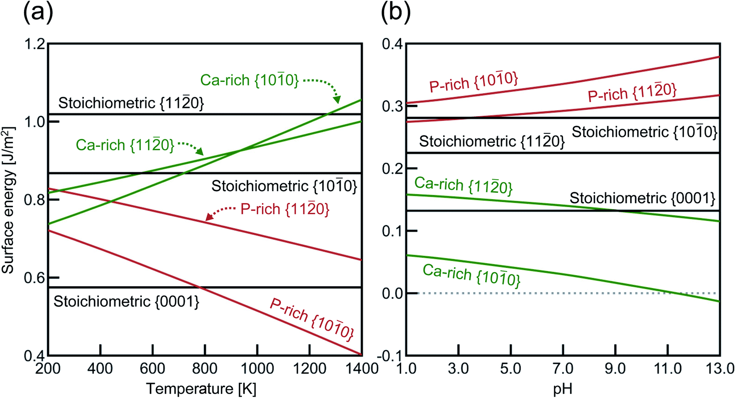 | ||
| Fig. 3 Calculated surface energies as a function of (a) temperature in the air atmosphere and (b) pH in the aqueous solution at 298 K. Black, green, and red lines correspond to stoichiometric, Ca-rich, and P-rich surfaces, respectively. For the respective terminations, surface structures showing the smallest total energies are selected, and their surface energies are plotted. | ||
In the aqueous solution (Fig. 3(b)), the Ca-rich {100} surface has the lowest ΔEs value in the entire pH range, even compared with the stoichiometric {0001} surface. It is also interesting to see that the P-rich {100} surface has the highest ΔEs value in aqueous solution, which is a quite in contrast to the case of the air atmosphere (see Fig. 3(a)). In the aqueous solution, the Ca-rich {100} surface is thus expected to be more preferentially formed than other P-rich {100} and {110} surfaces.
Previous DFT calculations indicated that the stoichiometric {0001} surface has ΔEs values of around 0.87 J m−2 under vacuum,55,56 which are higher than our calculated value (0.58 J m−2) in Fig. 3(a). Considering that the other {0001} surface had a similar ΔEs value (0.86 J m−2) under vacuum, this discrepancy probably comes from the difference in the Ca position at the outermost surface atomic layer. As stated in Fig. 2(a), there are two different {0001} surface structures with respect to the outermost Ca sites, labeled as Ca(1) and Ca(2). It seems that the Ca(1) occupation corresponds to the one treated in the abovementioned previous calculations, whereas, in the present study, the Ca(2) occupation is found to be energetically more stable with ΔEs = 0.58 J m−2. Such preference of the Ca(2) occupation is related to the coordination number of Ca(2). Fig. 4 displays atomic arrangements around the outermost Ca ions. At the {0001} surface, Ca(1) has three first nearest neighboring (1st NN) O ions at distances of 2.19–2.26 Å. In contrast, Ca(2) has six 1st NN O ions at distances of 2.38–2.58 Å. The higher coordination number of Ca(2) to O ions would thus contribute to the smaller ΔEs value.
 | ||
| Fig. 4 Relaxed atomic configurations on the stoichiometric {0001} surfaces with Ca2+ at (a) site 1 and (b) site 2, which are relaxed under vacuum. For clarity, only ions on top of the {0001} surface are displayed. | ||
Chiatti et al. performed similar DFT calculations and showed that in the air atmosphere, the stoichiometric {110} surface (1.22 J m−2) is smaller in ΔEs than for the stoichiometric {100} surface (1.35 J m−2).30 Their relative stability is different from the present results, i.e., {100} (0.87 J m−2) < {110} (1.02 J m−2), as shown in Fig. 3(a). A plausible reason for this difference is the fact that the present stoichiometric {100} surface is more significantly relaxed than the previously reported one. The difference in the relaxed surfaces would arise from structural optimization methods. The present study uses a conjugate-gradient (CG) algorithm, while Chiatti et al. used a quasi-Newton algorithm. Regarding VASP, it is officially suggested that the implemented quasi-Newton algorithm fails badly when the initial structure is far from the local minimum energy.70 In order to check the effect of the optimization methods, the two stoichiometric surfaces were thus again optimized using another quasi-Newton algorithm based on RMM-DIIS.57 As a result, the ΔEs value of {100} (1.09 J m−2) is found to be larger than that of the {110} surface (1.02 J m−2). The {100} surface obtained by the quasi-Newton algorithm is also less relaxed than that obtained by the CG algorithm. This suggests that the choice of an appropriate optimization algorithm is very important to find reasonable relaxed surfaces in structural relaxation calculation. However, the surface energies obtained by the quasi-Newton algorithm still are larger than those displayed in Fig. 3(a). It can be thus said that the relaxed surface structures obtained by the CG method should be more appropriate to represent the stoichiometric surfaces. More details are provided in Section S4 in the ESI.†
The surface energies for different surface orientations may be reflected in real HAp crystal shapes. For instance, HAp samples prepared by solution-precipitation methods typically have rod- or needle-like morphologies.16,58,59 Since the HAp crystal structure is hexagonal, such morphologies indicate that the lateral {100} surface is much more stable than the {0001} one, as can be seen in Fig. 3(b). Moreover, Liu et al. showed that HAp whiskers prepared by a hydrothermal method increase their aspect ratios with increasing pH from 6 to 9.60 This trend could also be expected from the increasing difference in ΔEs between {100} and {0001} with rising pH values (see Fig. 3(b)). On the other hand, Wang et al. investigated shape changes of HAp nanosized crystal rods at high temperatures, and showed that HAp nanorods gradually increase their {0001} surface areas in the temperature range of 300–700 °C.61 This indicates less stability of the P-rich {100} surface than the {0001} surface below 800 K (see Fig. 3(a)) in the air atmosphere, whose trend is also in good agreement with Fig. 3(a).
Regarding the nonstoichiometric {100} surface, the present calculations showed that the different chemical environments offer different atomic terminations: the P-rich one in the air atmosphere and the Ca-rich one in the aqueous solution (see Fig. 3). Although transmission electron microscopy should be a powerful means to identify such atomic structures, it is quite difficult to do so because HAp crystals seem to be easily subjected to electron-beam damages.25 In this regard, Sato et al. performed HRTEM observations of HAp crystals sintered at a high temperature and observed the facetted {100} surfaces in contact with amorphous HAp due to electron-beam damages. These authors determined that the facetted {100} surfaces are the Ca-rich surfaces.25 However, since the observed {100} surface is not a free surface that is treated in the present calculations, comparisons with the present results are not straightforward.
3.2 Surface atomic structures with and without an aqueous solution
In this section, characteristic atomic structures of surfaces in the different surrounding environments are investigated. Fig. 5 shows the unrelaxed and relaxed atomic structures at Ca-rich {100} surfaces. For the unrelaxed surface (Fig. 5(a)), the surface has a protruding Ca ion at its outermost site (labeled A). As shown in Fig. 5(b), the relaxed surface under vacuum involves significant surface relaxations: the Ca(A) ion is displaced by 0.83 Å from its original position toward the crystal, while the Ca(B) and an OH(C) ions are also displaced by 1.40 Å and 3.06 Å away from the surface, respectively. Such large atomic relaxations take place so as to make more Ca–O bonds around the surface plane.
 | ||
| Fig. 5 Atomic configurations of the Ca-rich {100} surface viewed along the c axis. (a) The unrelaxed structure, (b) the relaxed structure under vacuum, and (c) the relaxed structure with implicit solvation. | ||
In contrast, however, the surface in contact with the implicit solvent (Fig. 5(c)) exhibits much smaller atomic displacements. This is because missing Ca–O bonds at the surface can be compensated by electrostatic interactions of surface ions with charges formed on the surface of the solvent, as is clearly seen in Fig. 6. The negative and positive charges are induced in the solvent surface across the outermost Ca(A) and O(D) ions. Such smaller atomic relaxations and electrostatic interactions with the aqueous solution should lead to stabilization of the Ca-rich {100} surface shown in Fig. 3(b).
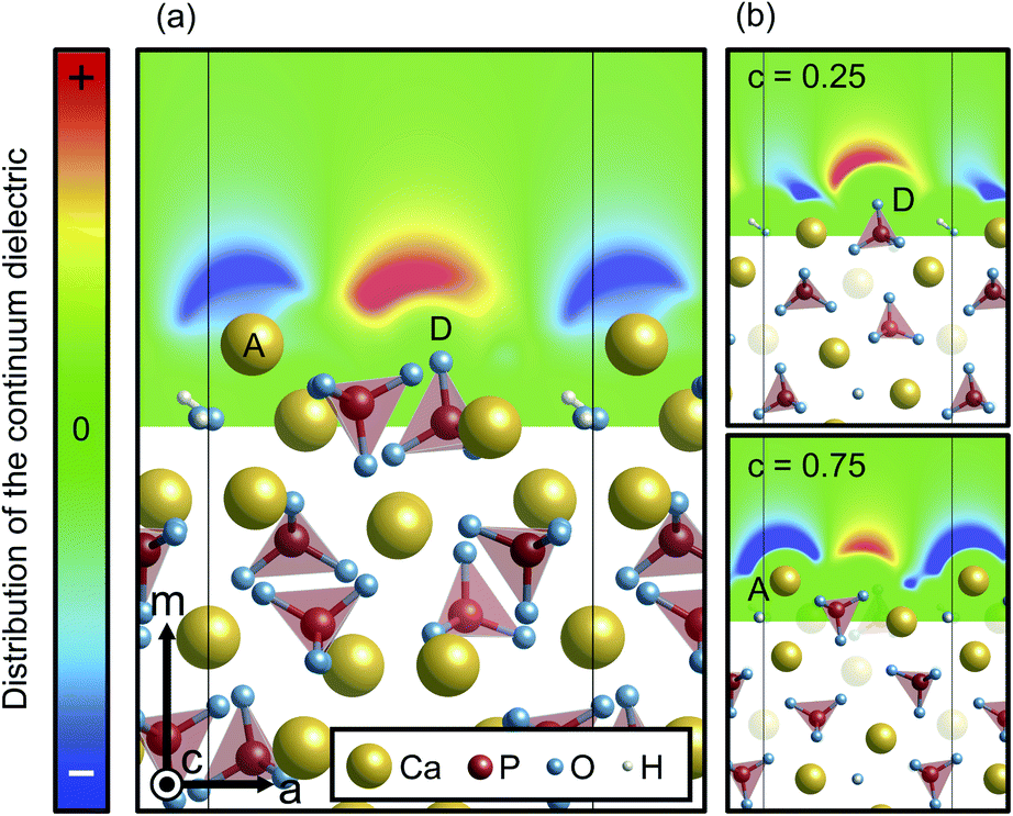 | ||
| Fig. 6 Distribution of the continuum dielectric, which indicates the ionic charge density of the electrolyte, (a) averaged along the c axis and (b) around O(D) and Ca(A) ions on the Ca-rich {100} surface. For the color scheme, its maximum (colored red) and minimum (blue) values were set to 1 × 10⁻¹⁰ and −1 × 10⁻¹⁰ e− Å−3, respectively. | ||
Unlike the Ca-rich {100} surface, the {0001} and the P-rich {100} surfaces, which are stable in the air atmosphere, show minor relaxations both under vacuum and in the implicit solvent, as displayed in Fig. 7. It is noted that only the P-pole {0001} surface is displayed in Fig. 7 because the relaxed P- and N-pole {0001} surface structures are found to be quite similar. For the two surfaces, the surface ions are displaced by only ∼0.8 Å under vacuum and ∼0.6 Å in the implicit solvent. Such smaller atomic relaxations of the {0001} and the P-rich {100} surfaces arise from their original atomic arrangements. For example, the outermost Ca(A) ion in the Ca-rich {100} surface (see Fig. 5) looks protruding from the underlying PO43− and OH− ions. This results in its small coordination numbers with the 1st NN and 2nd NN ions. As compared with Ca(A) of the Ca-rich {100} surface, outermost Ca ions of the {0001} and the P-rich {100} surfaces are located closer to the inner crystal layers, indicating their larger coordination numbers within 2nd NN ions. Owing to such more closely packed surface atomic arrangements, the {0001} and the P-rich {100} surfaces display smaller surface relaxations, irrespective of the surrounding surface environments.
 | ||
| Fig. 7 Relaxed atomic structures of P-rich {100} and P-pole {0001} surfaces. (a) Relaxed P-rich {100} under vacuum, (b) relaxed P-rich {100} in the implicit solvation, (c) relaxed P-pole {0001} under vacuum, (d) relaxed P-pole {0001} in the implicit solvation. Broken circles indicate original Ca positions before relaxation. | ||
3.3 Potential of zero charge and isoelectric point
Based on the relaxed surface structures in the implicit solvent, their φPZC values are evaluated using eqn (6), as summarized in Table 2. The stoichiometric P-pole and N-pole {0001} surfaces have almost the same φPZC values, and the {100} surfaces tend to exhibit smaller φPZC values. Among the {100} surfaces, the Ca-rich one, which is energetically most stable in the aqueous solution (Fig. 3), has the smallest φPZC value of 3.7 V. In order to reduce the surface potentials, surfaces with larger φPZC values in the aqueous solution can attract more negative hydroxyl ions. This can be rephrased by stating that the {0001} and ({100}) surfaces with larger (smaller) φPZC tend to take more negative (positive) charges.
0} surfaces with different terminations
| Surface | Surface potential φPZC [V] | |
|---|---|---|
| {0001} | P-pole | 4.1 |
| N-pole | 4.2 | |
| {100} |
P-rich | 3.9 |
| Ca-rich | 3.7 | |
| Stoichiometric | 4.0 | |
The above results fairly agree with conventional views of surface charge states of HAp crystals: the {0001} plane of HAp is negatively charged while the {100} plane is positively charged.11,16,17 This was understood from a conventional idea from chromatographic measurements that the {0001} surface is rich in PO43− ions and the {100} surface is rich in Ca ions.5,18–21 The present results can support this idea because the Ca-rich {100} surface and the stoichiometric {0001} surface (relatively PO4-rich) are most stable when HAp is in contact with an aqueous solution. The anisotropy of the surface charge states of HAp {0001} and {100} can lead to various pHPZC values depending on morphologies of HAp crystal grains, which were experimentally reported.6,17,62,63 Aizawa et al. also showed that surface zeta potentials of HAp shift from negative to positive values with increasing {100} surface areas at pH = 7.16 The present results can reasonably explain these experimental data on the basis of atomic-level structures of HAp {0001} and {100} surfaces.
As stated in Section 2.4, surface charge states of crystal grains are usually discussed by experimentally measurable pHPZC in electrochemistry and biochemistry. Therefore, pHPZC values of the energetically most stable Ca-rich {100} and {0001} surfaces in HAp are evaluated according to eqn (6) in Fig. 8. As proposed by McCafferty,42 it can be confirmed that φPZC has a linear relationship with pHPZC irrespective of oxide substances. On the basis of this relationship, the pHPZC values are estimated to be 4.0, 4.8, and 8.7 for the N-pole {0001}, P-pole {0001}, and Ca-rich {100} surfaces, respectively.
 | ||
| Fig. 8 Surface potentials φPZC plotted against pHPZC. The solid line with a gradient −0.120 V was obtained by least square regression according to the theoretical linear function proposed in ref. 45. | ||
The pHPZC indicates a pH value where protons and hydroxyl ions are balanced so that a surface is charge neutral. When a particular pH value is considered and is larger than pHPZC, the surface should be enriched with hydroxyl ions, resulting in a negatively charged surface. This is applicable to the stoichiometric {0001} surface because the physiological pH is 7.4, and the pH range from 5.0 to 9.0 is often used in the processing of HAp crystal grains. Conversely, the Ca-rich {100} surface having the larger pHPZC value tends to be positive. It can be said, therefore, that the present analyses can provide a quantitative description of the surface charge states of HAp crystal grains when they are immersed in aqueous solutions.
In the present study, DFT based theoretical analyses on surface charge states of HAp were carried out. It was found that the present methodologies can provide reasonable and quantitative descriptions of surface charge states, which should be promising to attain a theoretical understanding of atomic-level interactions with molecules and proteins in oxides and inorganic compounds as well as in calcium phosphates. It should be noted, however, that real surfaces may contain point defects and impurities, which may also affect the surface charge states. In fact, Yin et al. showed that zeta potentials of HAp are changed by not only pH values but also concentrations of Ca2+ and phosphate groups in the surrounding aqueous solution.6 Carbonate group and Na+ in aqueous solutions may also be included on the real surfaces.63,64 It can be expected that these issues can be theoretically clarified on the basis of the present methodologies, which should be addressed in future works.
It also should be noted that all water molecules were implicitly treated in the current study. For future studies considering explicit water molecules, the results will be validated using the revised Tao-Mo (revTM) functional, which is known to provide accurate water properties.65–67 It was found that the revTM provides more accurate lattice parameters of the HAp unit cell of 9.44 Å and 6.91 Å for the a and c axis, respectively, than the PBE functional with respect to the experimental data.34 On the other hand, the revTM predicts slightly higher surface energies than the PBE, to be 0.23 J m−2, 0.41 J m−2, and 0.39 J m−2 for the stoichiometric {0001}, {100}, and {110} surfaces, respectively. However, the order of the surface stability, namely {0001} > {110} > {100}, is the same as the PBE. The Ca-rich {100} surface has the φPZC value lower by 0.8 V than the P-pole {0001} surface. The result suggests a low pHPZC value of the Ca-rich {100} surface over the P-pole {0001} surface, which is also consistent with that provided by the PBE. Accordingly, the revTM functional would provide similar results as PBE, and be applicable to the investigation of HAp surfaces with explicit solvent.
4. Conclusions
HAp surface structures and their charge states were examined using first-principles based calculations. An implicit solvation model was employed to model HAp surfaces immersed in aqueous solutions. The present calculations demonstrated that the stoichiometric {0001} and the P-rich {100} surface are energetically most favorable, depending on the temperature, whereas in an aqueous solution, the Ca-rich {100} surface becomes most stable. This suggests that the presence of an aqueous solution is critical in determining the preference of surface terminations. On the basis of optimized surfaces, their surface potentials at zero charge were calculated to obtain the isoelectric point (pHPZC) of each surface. pHPZC values were found to be 4.8 and 8.7 for the {0001} surface and the Ca-rich {100} surface, respectively. It can be said that the {0001} and Ca-rich {100} surfaces are thus negatively and positively charged, respectively, in the aqueous solution at neutral pH. The anisotropy of surface charge states agrees with previous suggestions based on chromatographic behavior and zeta potential measurement. Our methodology based on first-principles calculations enables determining surface charge states quantitatively in the atomic and electronic level.
Conflicts of interest
There are no conflicts of interest to declare.Acknowledgements
This work was supported by JSPS KAKENHI (Grant Number 19K22048 and 19H05786) and by a research grant from Kyosho Hatta Foundation.References
- T. Noshi, T. Yoshikawa, M. Ikeuchi, Y. Dohi, H. Ohgushi, K. Horiuchi, M. Sugimura, K. Ichijima and K. Yonemasu, J. Biomed. Mater. Res., 2000, 52, 621–630 CrossRef CAS PubMed.
- H. Ohgushi, M. Okumura, S. Tamai, E. C. Shors and A. I. Caplan, J. Biomed. Mater. Res., 1990, 24, 1563–1570 CrossRef CAS PubMed.
- Y. Kuboki, H. Takita, D. Kobayashi, E. Tsuruga, M. Inoue, M. Murata, N. Nagai, Y. Dohi and H. Ohgushi, J. Biomed. Mater. Res., 1998, 39, 190–199 CrossRef CAS PubMed.
- A. H. Choi and B. Ben-Nissan, Nanomedicine, 2007, 2, 51–61 CrossRef CAS PubMed.
- T. Kawasaki, J. Chromatogr. A, 1991, 544, 147–184 CrossRef CAS.
- G. Yin, Z. Liu, J. Zhan, F. Ding and N. Yuan, Chem. Eng. J., 2002, 87, 181–186 CrossRef CAS.
- H. M. Kim, T. Himeno, T. Kokubo and T. Nakamura, Biomaterials, 2005, 26, 4366–4373 CrossRef CAS PubMed.
- H. M. Kim, T. Himeno, M. Kawashita, T. Kokubo and T. Nakamura, J. R. Soc., Interface, 2004, 1, 17–22 CrossRef CAS PubMed.
- I. S. Harding, N. Rashid and K. A. Hing, Biomaterials, 2005, 26, 6818–6826 CrossRef CAS PubMed.
- S. V. Dorozhkin, J. Colloid Interface Sci., 1997, 191, 489–497 CrossRef CAS PubMed.
- M. Aizawa, T. Matsuura and Z. Zhuang, Biol. Pharm. Bull., 2013, 36, 1654–1661 CrossRef CAS PubMed.
- F. Ryuichi and K. Yoshinori, Biochim. Biophys. Acta, Gen. Subj., 1991, 1075, 56–60 CrossRef.
- K. Kandori, H. Hamazaki, M. Matsuzawa and S. Togashi, Adv. Powder Technol., 2014, 25, 354–359 CrossRef CAS.
- T. Kanno, T. Sendai, K. Tada, J. Horiuchi and T. Akazawa, Phosphorus Res. Bull., 2007, 21, 25–30 CrossRef CAS.
- G. Kawachi, T. Watanabe, S. I. Ogata, M. Kamitakahara and C. Ohtsuki, J. Ceram. Soc. Jpn., 2009, 117, 847–850 CrossRef CAS.
- Z. Zhuang, T. J. Fujimi, M. Nakamura, T. Konishi, H. Yoshimura and M. Aizawa, Acta Biomater., 2013, 9, 6732–6740 CrossRef CAS PubMed.
- Z. Zhuang, H. Yoshimura and M. Aizawa, Mater. Sci. Eng., C, 2013, 33, 2534–2540 CrossRef CAS PubMed.
- G. Bernardi, M.-G. Giro and C. Gaillard, Biochim. Biophys. Acta, Protein Struct., 1972, 278, 409–420 CrossRef CAS.
- G. Bernardi and T. Kawasaki, Biochim. Biophys. Acta, Protein Struct., 1968, 160, 301–310 CrossRef CAS.
- T. Kawasaki, J. Chromatogr. A, 1974, 93, 313–335 CrossRef CAS.
- T. Kawasaki, J. Chromatogr. A, 1978, 151, 95–112 CrossRef CAS.
- W. E. Brown, Nature, 1962, 196, 1048–1050 CrossRef CAS.
- M. Aizawa, A. E. Porter, S. M. Best and W. Bonfield, Biomaterials, 2005, 26, 3427–3433 CrossRef CAS PubMed.
- M. Jevtić, M. Mitrić, S. Škapin, B. Jančar, N. Ignjatović and D. Uskoković, Cryst. Growth Des., 2008, 8, 2217–2222 CrossRef.
- K. Sato, T. Kogure, H. Iwai and J. Tanaka, J. Am. Ceram. Soc., 2004, 85, 3054–3058 CrossRef.
- C. A. Ospina, J. Terra, A. J. Ramirez, M. Farina, D. E. Ellis and A. M. Rossi, Colloids Surf., B, 2012, 89, 15–22 CrossRef CAS PubMed.
- F. Chiatti, M. Corno, Y. Sakhno, G. Martra and P. Ugliengo, J. Phys. Chem. C, 2013, 117, 25526–25534 CrossRef CAS.
- K. Sato, Y. Suetsugu, J. Tanaka, S. Ina and H. Monma, J. Colloid Interface Sci., 2000, 224, 23–27 CrossRef CAS PubMed.
- Y. Sakhno, P. Ivanchenko, M. Iafisco, A. Tampieri and G. Martra, J. Phys. Chem. C, 2015, 119, 5928–5937 CrossRef CAS.
- F. Chiatti, M. Delle Piane, P. Ugliengo and M. Corno, Theor. Chem. Acc., 2016, 135, 1–15 Search PubMed.
- R. Astala and M. J. Stott, Phys. Rev. B: Condens. Matter Mater. Phys., 2008, 78, 075427 CrossRef.
- G. Kresse and J. Furthmüller, Comput. Mater. Sci., 1996, 6, 15–50 CrossRef CAS.
- J. P. Perdew, K. Burke and M. Ernzerhof, Phys. Rev. Lett., 1996, 77, 3865–3868 CrossRef CAS PubMed.
- M. I. Kay, R. A. Young and A. S. Posner, Nature, 1964, 204, 1050–1052 CrossRef CAS PubMed.
- K. Mathew, V. S. C. Kolluru, S. Mula, S. N. Steinmann and R. G. Hennig, J. Chem. Phys., 2016, 151, 234101 CrossRef PubMed.
- K. Mathew, R. Sundararaman, K. Letchworth-Weaver, T. A. Arias and R. G. Hennig, J. Chem. Phys., 2014, 140, 084106 CrossRef PubMed.
- D. Zahn and O. Hochrein, Phys. Chem. Chem. Phys., 2003, 5, 4004–4007 RSC.
- C. Park, P. Fenter, Z. Zhang, L. Cheng and N. C. Sturchio, Am. Mineral., 2004, 89, 1647–1654 CrossRef CAS.
- A. Pareek, X. Torrelles, K. Angermund, J. Rius, U. Magdans and H. Gies, Langmuir, 2008, 24, 2459–2464 CrossRef CAS PubMed.
- P. Giannozzi, S. Baroni, N. Bonini, M. Calandra, R. Car, C. Cavazzoni, D. Ceresoli, G. L. Chiarotti, M. Cococcioni, I. Dabo, A. D. Corso, S. de Gironcoli, S. Fabris, G. Fratesi, R. Gebauer, U. Gerstmann, C. Gougoussis, A. Kokalj, M. Lazzeri, L. Martin-Samos, N. Marzari, F. Mauri, R. Mazzarello, S. Paolini, A. Pasquarello, L. Paulatto, C. Sbraccia, S. Scandolo, G. Sclauzero, A. P. Seitsonen, A. Smogunov, P. Umari and R. M. Wentzcovitch, J. Phys.: Condens. Matter, 2009, 21, 395502 CrossRef PubMed.
- R. M. H. Verbeek, H. Steyaer, H. P. Thun and F. Verbeek, J. Chem. Soc., Faraday Trans. 1, 1980, 76, 209–219 RSC.
- T. Kubota, A. Nakamura, K. Toyoura and K. Matsunaga, Acta Biomater., 2014, 10, 3716–3722 CrossRef CAS PubMed.
- K. Matsunaga and A. Kuwabara, Phys. Rev. B: Condens. Matter Mater. Phys., 2007, 75, 014102 CrossRef.
- K. Matsunaga, Phys. Rev. B: Condens. Matter Mater. Phys., 2008, 77, 104106 CrossRef.
- E. McCafferty, Electrochim. Acta, 2010, 55, 1630–1637 CrossRef CAS.
- D. J. Kim, H. Kim and J. K. Lee, J. Mater. Sci., 1998, 33, 2931–2935 CrossRef CAS.
- M. Robinson, J. A. Pask and D. W. Fuerstenau, J. Am. Ceram. Soc., 1964, 47, 516–520 CrossRef CAS.
- A. L. Valdivieso, J. L. R. Bahena, S. Song and R. H. Urbina, J. Colloid Interface Sci., 2006, 298, 1–5 CrossRef PubMed.
- M. E. Labib and R. Williams, Colloid Polym. Sci., 1986, 264, 533–541 CrossRef CAS.
- K. Bourikas, J. Vakros, C. Kordulis and A. Lycourghiotis, J. Phys. Chem. B, 2003, 107, 9441–9451 CrossRef CAS.
- C. Bellmann, C. Klinger, A. Opfermann, F. Böhme and H. J. P. Adler, Prog. Org. Coat., 2002, 44, 93–98 CrossRef CAS.
- A. Kasha, H. Al-Hashim, W. Abdallah, R. Taherian and B. Sauerer, Colloids Surf., A, 2015, 482, 290–299 CrossRef CAS.
- D. A. Mahrouqi, J. Vinogradov and M. D. Jackson, Adv. Colloid Interface Sci., 2017, 240, 60–76 CrossRef PubMed.
- S. L. S. Stipp, Geochim. Cosmochim. Acta, 1999, 63, 3121–3131 CrossRef CAS.
- P. Rulis, H. Yao, L. Ouyang and W. Y. Ching, Phys. Rev. B: Condens. Matter Mater. Phys., 2007, 76, 245410 CrossRef.
- A. Slepko and A. A. Demkov, J. Chem. Phys., 2013, 139, 044714 CrossRef PubMed.
- P. Pulay, Chem. Phys. Lett., 1980, 73, 393–398 CrossRef CAS.
- H. Zhang and B. W. Darvell, Acta Biomater., 2011, 7, 2960–2968 CrossRef CAS PubMed.
- C. Kothapalli, M. Wei, A. Vasiliev and M. T. Shaw, Acta Mater., 2004, 52, 5655–5663 CrossRef CAS.
- J. Liu, X. Ye, H. Wang, M. Zhu, B. Wang and H. Yan, Ceram. Int., 2003, 29, 629–633 CrossRef CAS.
- J. Wang and L. L. Shaw, Adv. Mater., 2007, 19, 2364–2369 CrossRef CAS.
- E. Landi, G. Celotti, G. Logroscino and A. Tampieri, J. Eur. Ceram. Soc., 2003, 23, 2931–2937 CrossRef CAS.
- L. C. Bell, A. M. Posner and J. P. Quirk, Nature, 1972, 239, 515–517 CrossRef CAS.
- E. Skwarek and W. Janusz, Mater. Sci., 2016, 22, 174–178 CrossRef.
- S. Jana, A. Patra, S. Śmiga, L. A. Constantin and P. Samal, J. Chem. Phys., 2020, 153, 214116 CrossRef CAS PubMed.
- S. Jana, K. Sharma and P. Samal, J. Phys. Chem. A, 2019, 123, 6356–6369 CrossRef CAS PubMed.
- S. Jana, L. A. Constantin and P. Samal, J. Chem. Theory Comput., 2020, 16, 974–987 CrossRef CAS PubMed.
- M. W. Chase, NIST-JANAF Thermochemical Tables, American Institute of Standards and Technology, New York, 4th edn, 1998 Search PubMed.
- D. D. Wagman, W. H. Evans, V. B. Parker, R. H. Schumm, I. Halow, S. M. Bailey, K. L. Churney and R. L. Nuttall, J. Phys. Chem. Ref. Data, 1982, 11(suppl. 2), 38–267 Search PubMed.
- The VASP Manual – Vaspwiki, accessed July 2021, https://www.vasp.at/wiki/index.php/IBRION#cite_note-pulay:cpl:80-1.
Footnote |
| † Electronic supplementary information (ESI) available. See DOI: 10.1039/d1ra06311a |
| This journal is © The Royal Society of Chemistry 2021 |