
 Open Access Article
 This Open Access Article is licensed under a Creative Commons Attribution-Non Commercial 3.0 Unported Licence
Preparation of graphene/polypropylene composites with high dielectric constant and low dielectric loss via constructing a segregated graphene network
Lijing Han a,
Hairui Wanga,
Qi Tanga,
Xiurui Langa,
Xuemeng Wanga,
Yingxia Zong*b and
Chengzhong Zonga
a,
Hairui Wanga,
Qi Tanga,
Xiurui Langa,
Xuemeng Wanga,
Yingxia Zong*b and
Chengzhong Zonga
aSchool of Polymer Science and Engineering, Qingdao University of Science and Technology, Qingdao 266042, China
bCollege of Chemical and Molecular Engineering, Qingdao University of Science and Technology, Qingdao 266042, China. E-mail: zongyingxia@126.com
First published on 29th November 2021
Abstract
In this paper, a reduced graphene oxide/polypropylene (rGO/PP) dielectric composite with high dielectric constant and low dielectric loss at a low filler content was prepared via constructing a segregated moderately-reduced graphene network by encapsulation of GO on PP latex particles and subsequent in situ reduction of GO by hydrazine hydrate. GO/PP latex was prepared through artificial PP latex preparation in the presence of GO based on the solution-emulsification technique. As the emulsification proceeded, GO could self-assemble to become encapsulated on the surface of PP latex particles composed of PP and maleic-anhydride-grafted-PP because of the hydrogen bonding interaction between maleic-anhydride-grafted-PP and GO nanosheets. After reduction, the rGO encapsulated PP latex particles were obtained, and after coagulation and hot pressing, a segregated graphene network was achieved at a low content of rGO, demonstrated by TEM images. The dielectric constant at 1 kHz obviously increased from 3.28 for PP to 55.8 for the composite with 1.5 wt% rGO. The dielectric loss of the composite was retained at a low value (1.04). This study provides a new simple and effective strategy for preparing high-performance dielectric composites with high dielectric constant and low dielectric loss, facilitating the wide application of dielectric materials.
Introduction
With the rapid development of flexible electronic devices and large-scale energy storage technologies, polymer-based dielectric materials with a high dielectric constant (high k) and low dielectric loss are attracting more attention because of their inherent advantages of being easy to process, flexible, light-weight and low cost. As we know, common polymers are obviously unsuitable for dielectric material applications because of their intrinsic low dielectric constant (approximately 2 to 10).1 Thus, a key issue is to enhance the dielectric constant of polymers while retaining other excellent properties such as low dielectric loss, and good flexibility. One common approach is to introduce high-dielectric-constant ceramic fillers (e.g., PbTiO3 and BaTiO3 (ref. 2)) into polymers. In this case, a high loading (up to 50 vol%) of ceramic fillers is often required to arrive at the desired dielectric constant of about 50 in the ceramic/polymer composites,3 resulting in processing difficulties, low flexibility, and excessive weight, all of which limit the wide application of composites. Another widely used approach is to prepare percolative composites by introducing conductive fillers such as metal particles,4 carbon nanotubes (CNTs)5–7 or graphene sheets8 into polymers. In percolative composites, the dielectric constant can be significantly enhanced when the volume fraction of the conductive filler gets close to the percolation threshold. However, the increase in dielectric constant is usually accompanied with a huge increase in dielectric loss due to the insulator–conductor transition, restricting further application toward dielectric materials for percolative composites.9Polypropylene (PP) is one of the most common thermoplastics which has long been used as the dielectric material in capacitors due to its outstanding dielectric properties. To the preparation of high energy density capacitors, recent research on PP focuses on substantially improving the dielectric constant while retaining low dielectric loss.10 In order to enhance the dielectric constant of PP, an effective method is to prepare percolative PP composite by adding graphene. However, there are two great challenges in this method. One is to realize the homogeneous dispersion of graphene sheets in PP matrix. Another one is to retain the low dielectric loss of PP because the direct connection between graphene sheets results in a high leakage current, thus a high dielectric loss.
Recently, a versatile and environment-friendly latex technology has been utilized to fabricate polymeric nanocomposites based on carbon nanotubes11 and graphene.12,13 However, to the best of our knowledge, in all reports on the preparation of graphene/PP composites through latex technology, the so-called PP latex used is a water-based emulsion of maleic-anhydride-grafted-isotactic polypropylene (PP-g-MA) with relatively low molecular weight as the matrix, because the production of PP in aqueous dispersion is limited due to the need of water-sensitive catalysts. In addition, some studies have reported that polymer composites with a three-dimensional (3D) segregated filler network can be prepared by distributing conductive fillers (carbon black, CNTs or graphene) at the interfaces between the polymer particles.14–16 These composites with this specific structure have a much lower percolation threshold compared to conventional composites with randomly distributed conductive fillers. For instance, Xia et al.17 prepared vulcanized natural rubber composites with a segregated graphene network by using latex mixing. The formation of a segregated graphene network largely improved the electrical conductivity, water vapor permeability and mechanical properties and reduced the electrical percolation threshold of the as-prepared composites. Liu et al.18 fabricated styrene butadiene rubber (SBR) rubber composites with a three-dimensional segregated graphene network (IL-3DGE) by pre-construction method, synchronously having good electrical conductivity, mechanical and gas barrier properties. They reported that the electrical percolation threshold (0.39 vol%) of the segregated SBR/IL-3DGE was approximately 9-fold lower than that of the non-segregated SBR/IL-GE (3.78 vol%). We are inspired by these studies to construct a segregated graphene network in PP matrix by latex technique to obtained graphene/PP composites with high dielectric constant and low dielectric loss at a low filler content.
Graphene oxide (GO), a precursor for graphene, was fabricated by the oxidation and exfoliation of graphite, bearing hydroxyl (C–OH) and epoxide (C–O–C) functional groups on their basal planes, in addition to carbonyl (C![[double bond, length as m-dash]](https://www.rsc.org/images/entities/char_e001.gif) O) and carboxyl groups (OC–OH) located at the nanosheets edges.19 These oxygen-containing groups enable GO nanosheets to uniformly disperse in polymer latex by ultrasonic, facilitating the preparation of GO/polymer composites with a segregated filler network. However, many studies have demonstrated that the increase in dielectric constant is far less than expected by using GO nanosheets as dielectric fillers because GO nanosheets are electrically insulated and exhibit no dielectric properties. Jiang et al.20 reported compared to the pure TPU in the measured frequency range, the dielectric constant and dielectric loss of the composites with 5 wt% and 15 wt% GO were nearly invariable. Therefore, reduction of GO in GO/polymer latex is required to increase the interfacial polarization ability of GO nanosheets. In addition, many studies have demonstrated that highly reduced GO (HrGO) nanosheets in the polymer composites can cause a large direct current (DC) conductance and thus a high dielectric loss near the percolation threshold,21 limiting further application as the dielectric material. Therefore, in order to obtain graphene/polymer dielectric composites with both high k and low dielectric loss, it is vital to simultaneously increase the interfacial polarization ability of GO nanosheets and keep a low leakage current of the composites by the moderate reduction in graphitic structure.
O) and carboxyl groups (OC–OH) located at the nanosheets edges.19 These oxygen-containing groups enable GO nanosheets to uniformly disperse in polymer latex by ultrasonic, facilitating the preparation of GO/polymer composites with a segregated filler network. However, many studies have demonstrated that the increase in dielectric constant is far less than expected by using GO nanosheets as dielectric fillers because GO nanosheets are electrically insulated and exhibit no dielectric properties. Jiang et al.20 reported compared to the pure TPU in the measured frequency range, the dielectric constant and dielectric loss of the composites with 5 wt% and 15 wt% GO were nearly invariable. Therefore, reduction of GO in GO/polymer latex is required to increase the interfacial polarization ability of GO nanosheets. In addition, many studies have demonstrated that highly reduced GO (HrGO) nanosheets in the polymer composites can cause a large direct current (DC) conductance and thus a high dielectric loss near the percolation threshold,21 limiting further application as the dielectric material. Therefore, in order to obtain graphene/polymer dielectric composites with both high k and low dielectric loss, it is vital to simultaneously increase the interfacial polarization ability of GO nanosheets and keep a low leakage current of the composites by the moderate reduction in graphitic structure.
To the best of our knowledge, high-performance graphene/PP dielectric composites with a segregated network structure have not been reported yet. In this study, we aim to prepare graphene/PP dielectric composites with high dielectric constant and low dielectric loss at a low filler content via constructing a segregated moderately-reduced graphene network by encapsulating of GO on PP latex particles and subsequent in situ reduction in GO by hydrazine hydrate. The GO/PP latex was produced through artificial PP latex preparation in the presence of GO based on solution-emulsification technique where the organic phase of PP and PP-g-MA in cyclohexane was added to the aqueous phase of emulsifiers in deionized water with vigorous agitation. As the emulsification proceeded, the encapsulation of GO nanosheets on the surface of PP latex particles was realized because of the hydrogen bonding interaction between the carboxyl group on PP-g-MA and oxygen-containing groups on GO nanosheets. Then, GO nanosheets in GO/PP latex were in situ reduced by hydrazine hydrate at 85 °C for 5 h to obtain the reduced GO/PP (rGO/PP) latex. The above-mentioned strong interaction made rGO encapsulate on PP latex particles rather than aggregate during hydrazine reduction process. The distribution of rGO at the interfaces between PP latex particles and the formation of a segregated graphene network were realized during hot pressing. The microstructure and dielectric properties of the graphene/PP composites and the underlying mechanism were investigated.
Experimental
Raw materials
Polypropylene (PP 4220) is a copolymer of propylene and ethylene and was purchased from Sinopec Yanshan Petrochemical Company. Maleic-anhydride-grafted-polypropylene (PP-g-MA, Fusabond® P353) was generously donated by Dupont. Graphene oxide slurry (1 wt% solid content) was procured from the Sixth Element (Changzhou) Materials Technology Co., Ltd. Potassium oleate was purchased from Macklin. Isomeric alcohol ethoxylate (TO-8) with a HLB value of 12.8 was purchased from BASF. Cyclohexane, span 80, poly (ethylene glycol) with average Mn of 6000 (PEG6000) and hydrazine hydrate (85%) were purchased from Sinopharm and used as received.Characterization
Dynamic light scattering (DLS) measurements were performed on a Malvern Zetasizer Nano ZS90 with a scattering angle of 90° to determine the particle-size distribution of the composite latex. Transmission electron microscope (TEM) observation was performed on a JEM2100 instrument with an accelerating voltage of 200 kV. For the composite latex, the latex after 10 times dilution was directly dropped on a copper grid for observation. For the composite, the sample was obtained by freezing ultra-thinned sectioning with a thickness of ∼100 nm. Fourier transform infrared spectroscopy (FT-IR) was recorded by a Bruker Vertex 70 FT-IR spectrometer with a scan range of 400–4000 cm−1 in ATR mode. A Renishaw InVia Reflex Raman system with 512 nm IR-diode laser coupled to an optical microscope was used to record spectra from the samples. X-ray diffraction (XRD) was carried out using a Rigaku X-ray generator from 2θ values ranging from 5–35° at room temperature. Thermogravimetric analysis (TGA) was carried out in a nitrogen atmosphere with a heating rate of 10 °C min−1 with a temperature range of 36–800 °C by using the TG209F3 instrument. The dielectric properties and alternating-current (AC) conductivity of the rGO/PP composites (25 mm diameter and 1 mm thickness, coated with silver paste) were measured by using an Alpha-A High-Performance Frequency Analyzer in the range of 102–107 Hz at room temperature. The breakdown strength was obtained according to GB/T 1408.1-2016 using a voltage breakdown tester (Air Times, ZJC-50 KV) equipped with two circular electrodes in the bath of the transformer oil. The pressurization speed is 1 kV s−1.Preparation of GO/PP latex
The GO/PP latex was fabricated through artificial PP latex preparation in the presence of GO based on solution-emulsification technique. Firstly, 3.6 g PP and 0.4 g PP-g-MA was added into 96 g cyclohexane and stirred gently at 85 °C for 6 h (organic phase). A desired amount of GO slurry was mixed with the aqueous solution of potassium oleate, TO-8, span 80, PEG6000 under magnetic stirring for 1 h (aqueous phase). The PH value of the aqueous phase was controlled to be 13 by adding 20% potassium hydroxide aqueous solution. The recipes for aqueous phases can be shown in Table 1. Secondly, the organic phase was added into the aqueous phase at 70 °C at 4000 rpm, followed by emulsification at 12![[thin space (1/6-em)]](https://www.rsc.org/images/entities/char_2009.gif) 000 rpm for 10 min with applying high shear dispersing emulsifiers (FLUKO FM200). Finally, cyclohexane was removed by distillation at 50 °C under reduced pressure.
000 rpm for 10 min with applying high shear dispersing emulsifiers (FLUKO FM200). Finally, cyclohexane was removed by distillation at 50 °C under reduced pressure.
| Aqueous phase | 1 | 2 | 3 |
|---|---|---|---|
| Potassium oleate (g) | 2 | 2 | 2 |
| TO-8 (g) | 0.8 | 0.8 | 0.8 |
| Span 80 (g) | 0.2 | 0.2 | 0.2 |
| PEG6000 (g) | 0.02 | 0.02 | 0.02 |
| GO slurry (g) | 2.7 | 5.5 | 8 |
| Deionized water (g) | 94.28 | 91.48 | 88.98 |
Preparation of rGO/PP latex and rGO/PP composites
The GO/PP latex was mixed with hydrazine hydrate for 30 min at room temperature, then the resulting mixture was heated in an oil bath at 85 °C for 5 h under gentle stirring. The weight ratio of hydrazine to GO was controlled to be 15:1. Then the rGO/PP latex was coagulated by adding alcohol as the flocculating agent quickly under magnetic stirring to avoid the self-aggregation of rGO, thus obtaining the well-dispersed rGO/PP composites. The coagulated composites were washed with deionized water to remove the emulsifiers and hydrazine and then dried in a vacuum oven at 70 °C for 24 h. Subsequently, the obtained rGO/PP composites were compression molded at 180 °C under 10 MPa for 10 min.
For comparison, the PP latex without GO was prepared through the same procedures. It is worth noting that the PP mentioned later refers to the mixture of PP and PP-g-MA with a weight ratio of 9:1. To calculate the rGO content in the resultant rGO/PP composites, the reduction yield of GO to rGO at the same condition afore-mentioned was needed. A required amount of hydrazine hydrate was added into the diluted GO suspension and mixed for 30 min, followed by reduction at 85 °C for 5 h. Finally, the black solid products were collected, dried, and weighed. A reduction yield of ∼75% was obtained. Therefore, the weight contents of rGO in the resultant rGO/PP composites were 0.5, 1 and 1.5 wt%, abbreviated as rGO/PP-0.5, rGO/PP-1 and rGO/PP-1.5.
Results and discussion
Mechanism for the formation of rGO segregated network
The rGO/PP composites were fabricated through artificial PP latex preparation in the presence of GO based on solution-emulsification technique and a subsequent in situ reduction of GO by hydrazine hydrate. The stable and well-dispersed GO/PP and rGO/PP latexes (Φ = 1.5 wt%) are shown in Fig. 1a. Fig. 1b shows size distribution profiles of the GO/PP and rGO/PP latexes (Φ = 1.5 wt%) with dynamic light scattering (DLS). We find a bimodal size distribution for the latexes. The two peaks with diameters about 290 nm and 4700 nm are attributed to PP latex particles and GO/rGO nanosheets respectively, as demonstrated by Fig. 1c and d. The two peaks for the rGO/PP latex (299 nm, 4800 nm) increase slightly compared to that for GO/PP latex (290 nm, 4670 nm), indicating that during the hydrazine reduction process, the obtained rGO nanosheets did not obviously agglomerate due to the presence of PP latex particles.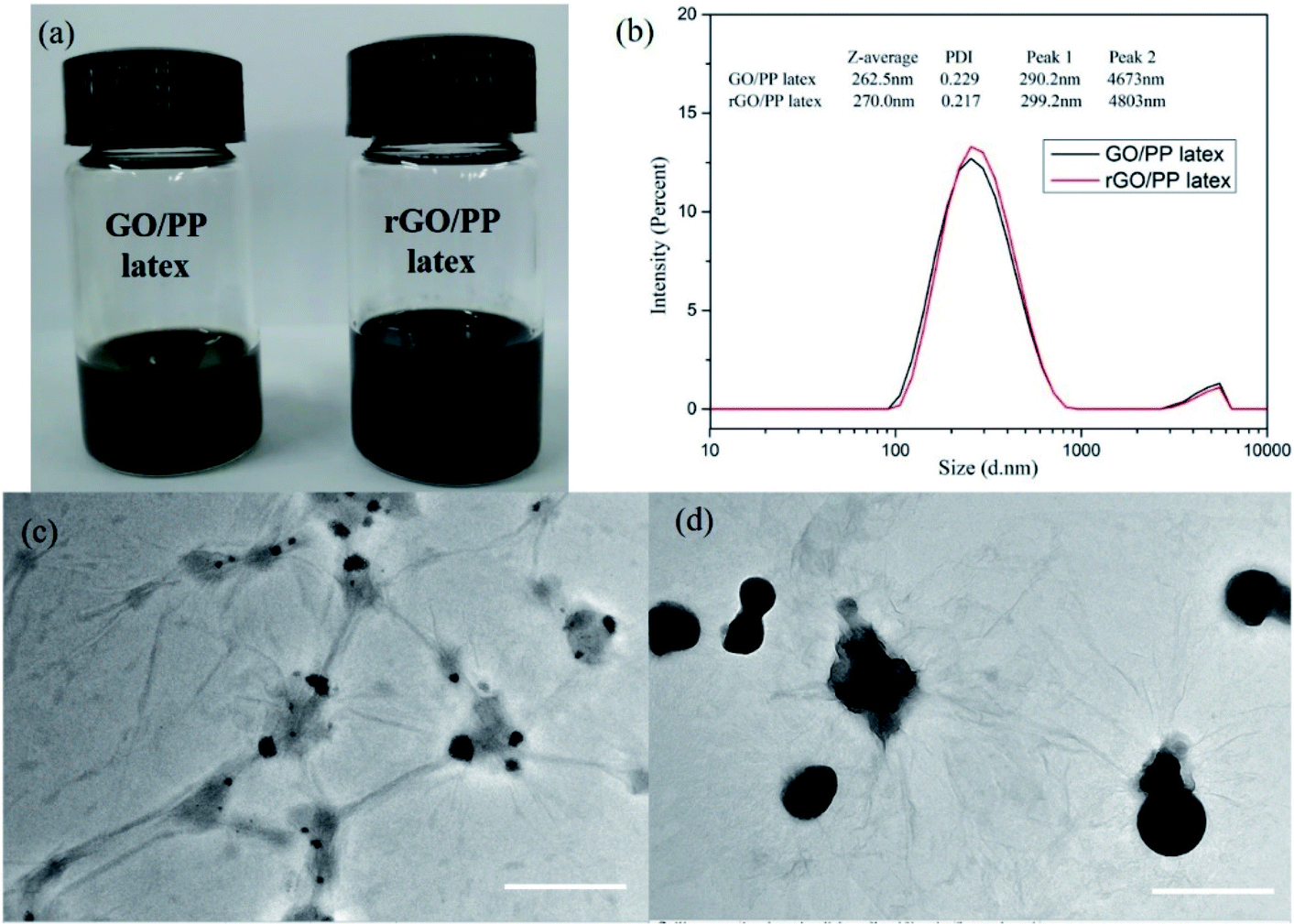 | ||
| Fig. 1 (a) Digital photograph (b) particle-size distribution profiles of the GO/PP and rGO/PP latexes, TEM images of (c) GO/PP latex and (d) rGO/PP latex (Φ = 1.5 wt%). Scale bars of (c and d) are 1 μm. | ||
The encapsulation of GO/rGO on PP latex particles is demonstrated by TEM images of GO/PP and rGO/PP latexes (Φ = 1.5 wt%), as shown in Fig. 1c and d. To better observe the morphology of the GO/rGO and PP latex particle in the composite latex, the composite latex was diluted 10 times. It is interesting to note that PP latex particles are coated by the wrinkled GO nanosheets, as shown in Fig. 1c. This confirms that as the emulsification proceeded, the wrinkled GO nanosheets can be self-assembled to adsorb onto the surface of the PP latex particles under the strong interaction between the PP latex particles and GO, thus forming the GO encapsulated PP latex particles. During the in situ reduction of GO in composite latex by hydrazine hydrate, hydrophilic GO became hydrophobic rGO as a result of the disappearance of oxygen-containing groups. We can also observe the wrinkled rGO encapsulated PP latex particles and no obvious agglomeration, as shown in Fig. 1d. Combined with Fig. 1a, the results show that during the reduction process, the demulsification of composite latex and the aggregation of rGO don't occur due to the strong interaction between PP latex particles and rGO. The formed rGO coating is the prototype of the rGO segregated network in the PP composites.
An FT-IR spectrum of dried PP latex is shown in Fig. 2a. This figure also shows the spectrum of PP-g-MA pellet as a comparison. For PP-g-MA pellet, we can observe the multiple peaks near 3000 cm−1 attributing to the C–H stretching vibration and the characteristic absorption peaks at 1455 cm−1 and 1375 cm−1 assigning to the C–H bending vibration. In the spectrum of dried PP latex, the absorption peak at 1722 cm−1 for carbonyls and an additional wide absorption peak at about 3500 cm−1 appear, revealing the existence of free carboxylic acid, and the absorption peak at 1577 cm−1 indicates the formation of a carboxylate salt structure.22 These observations indicate that most of the maleic anhydride groups on PP-g-MA chains in the PP latex particles have been hydrolyzed into carboxylic acid groups, and part of the carboxylic acids have reacted with emulsifiers to form carboxylate salts. Therefore, we speculate that the strong interaction between PP latex particles and GO or rGO originates from the hydrogen bonding interaction between the carboxyl groups on PP-g-MA chains and oxygen-containing groups on GO or rGO surfaces (see in Fig. 2b). This strong interaction is also confirmed by using Raman spectroscopy, which will be discussed in the following paragraph.
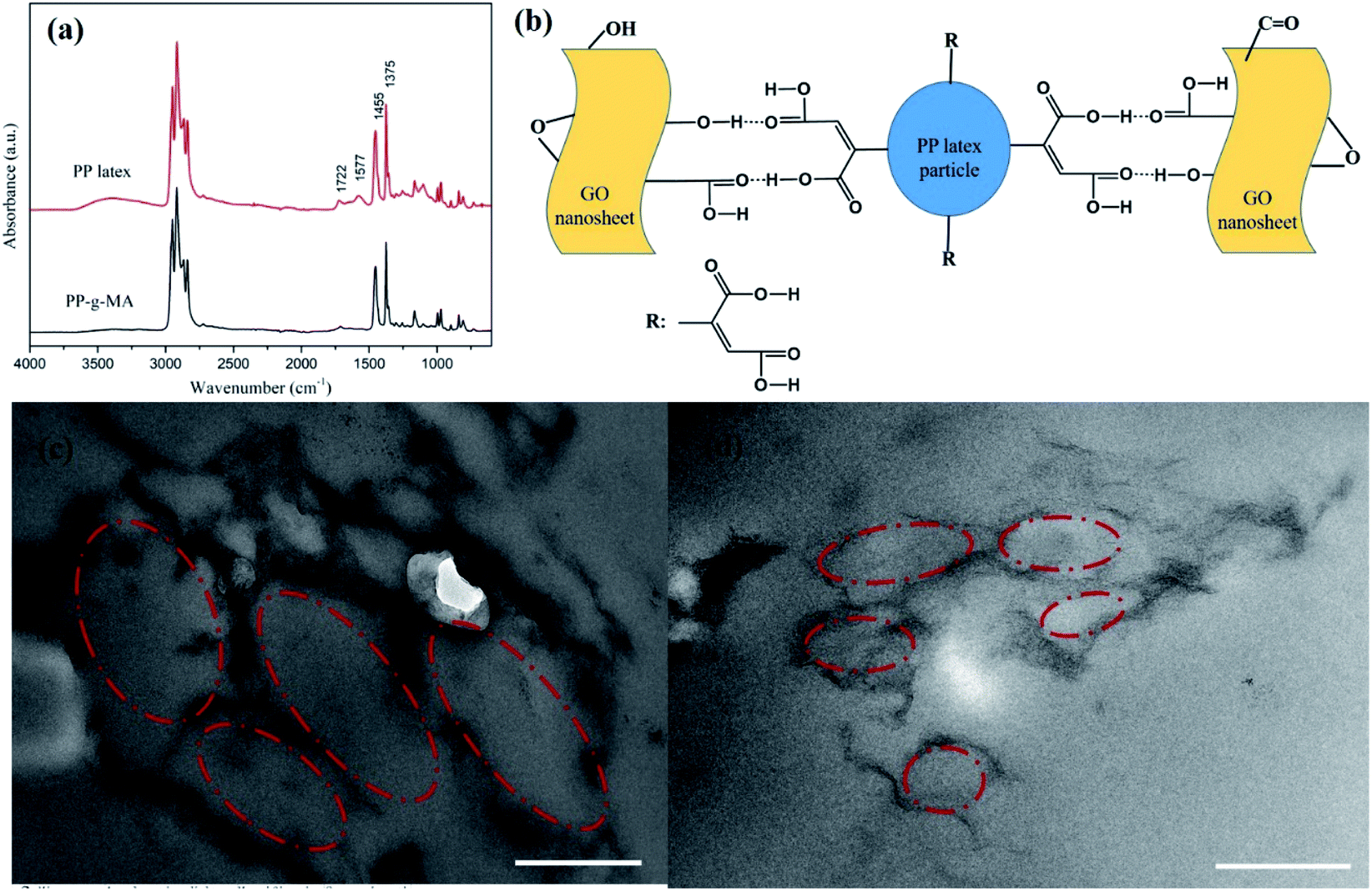 | ||
| Fig. 2 (a) FT-IR spectra of PP-g-MA and PP latex, (b) schematic representation of the strong interaction between GO and PP latex particle, TEM images of rGO/PP composites with different contents of rGO: (c) 1 wt%, (d) 1.5 wt%. Scale bars of (c and d) are 500 nm. | ||
The mechanism for the encapsulation of GO nanosheets on PP latex particles and the formation of rGO segregated network is proposed as follows. The GO/PP latex was first produced through the artificial PP latex preparation in the presence of GO based on solution-emulsification technique. The presence of the above-mentioned strong interaction made the GO nanosheets self-assemble to adsorb onto the surface of PP latex particles as the emulsification proceeded, realizing the encapsulation of GO nanosheets on PP latex particles. In addition, the π–π interaction between GO nanosheets and carbon–carbon double bonds of PP-g-MA chains might also play a role in the encapsulation of GO nanosheets on PP latex particles. The GO nanosheets in the GO/PP latex were then reduced by hydrazine hydrate. During the reduction process, no obvious agglomeration was observed and the encapsulation of rGO nanosheets on PP latex particles was realized due to the strong interaction. The formed rGO coating on the PP latex particles was the prototype of the rGO segregated network in the PP composites. The rGO encapsulated PP composites were produced by coagulation of the rGO/PP latex and subsequent hot pressing. The unique rGO segregated network was formed because the solid PP particles create an excluded volume and essentially push the rGO nanosheets distributing into the interstitial space between them during the hot-pressing process. In addition, the rGO segregated network structure along the boundary region was retained when cooled because it is quite difficult for rGO to diffuse inside the PP due to the high viscosity of the molten PP particles, as evidenced in Xia et al.'s work.17
Microstructure of rGO/PP composites
The formed segregated network structure of rGO is demonstrated by TEM images of rGO/PP composites (Φ = 1 and 1.5 wt%) prepared by hot pressing, as shown in Fig. 2c and d. In Fig. 2c, we observe the PP latex particle (core) encapsulated with rGO shell. The darker lines represent the rGO nanosheets and the gray parts correspond to PP latex particles becoming irregular under hot pressing. In addition, rGO shells encapsulated on the surface of PP latex particles, which are uniformly distributed in the PP matrix, are connected to form a segregated network structure, as shown in Fig. 2c. The thickness of these rGO shells is in nanoscale. As the content of rGO further increasing up to 1.5 wt%, the size of core–shell structured rGO/PP latex particles constructing segregated network decreases, and the rGO segregated network is more complete, as shown in Fig. 2c and d.In the rGO/PP composites with a segregated rGO network, rGO nanosheets are primarily located at the interfaces between the PP latex particles instead of being randomly distributed throughout the bulk composites. Due to the perfect mutual contact between rGO nanosheets in the interfacial regions of the rGO/PP composites, this unique network structure results in the composites with an efficient transport network, and dramatically reduces the percolation threshold compared with the random network structure (traditional structure).
In addition, XRD was also performed to roughly evaluate the thickness of rGO coated on PP latex particles. As shown in Fig. 3, the XRD profile of GO shows a strong (002) peak (2θ = 11.3°), showing that the interlayer distance of GO is 0.78 nm. For rGO, a weak and broad peak centered at about 23.5° (d002) can be seen, indicating that the aggregation of rGO nanosheets occurs after hydrazine reduction. The characteristic diffraction peaks at 2θ = 14.1°, 16.9°, 18.6°, 21.6° and 25.5° are observed for PP, corresponding to the (110), (040), (130), (111) + (041) and (060) crystalline planes of α-form PP, respectively. For the GO/PP and rGO/PP composites, the increase in peak intensity at 2θ = 16.9° is readily observed and the peak at 2θ = 25.5° becomes more obvious, indicating that the introduction of GO or rGO can affect the crystallization behaviour of PP matrix to some extent.
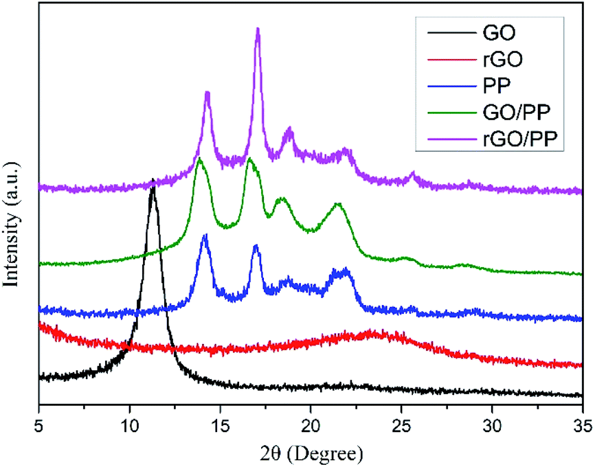 | ||
| Fig. 3 X-ray diffraction patterns for GO, rGO, PP, GO/PP and rGO/PP composites (Φ = 1.5 wt%). | ||
In addition, in the XRD profiles of the GO/PP and rGO/PP composites, no diffraction peaks are observed except the crystalline diffraction peaks of the PP matrix. The diffraction peaks corresponding to GO and the aggregation of rGO nanosheets cannot be detected, indicating that the thickness of GO or rGO coating is less than 3 nm.23 Thus, no significant restacking of rGO occurs during hydrazine reduction and subsequent coagulation process. This ensures the formation of a segregated rGO network in the rGO/PP composites at a low filler content. It is worth noting that the thickness of rGO shells encapsulated on PP latex particles seems much thicker in TEM images due to the disordered stack of rGO coating with a thickness of less than 3 nm (see XRD results) at the boundary between PP latex particles, which is consistent with the report of Ning et al.24
In situ chemical reduction in GO/PP latexes
TGA was carried out to evaluate the degree of reduction in GO nanosheets and study the thermal stability of PP, GO/PP and rGO/PP composites. The mass loss of GO and rGO at a heating rate of 10 K min−1 in a nitrogen atmosphere is presented in Fig. 4a. The mass loss of GO is up to 27% at 250 °C, whereas that of rGO is only about 7%, suggesting that plentiful oxygen-containing groups have been removed during in situ hydrazine reduction process. The mass loss of rGO continues with increasing temperature, suggesting that oxygen-containing groups of rGO are not completely removed during hydrazine reduction. These results demonstrate the moderate reduction in GO nanosheets.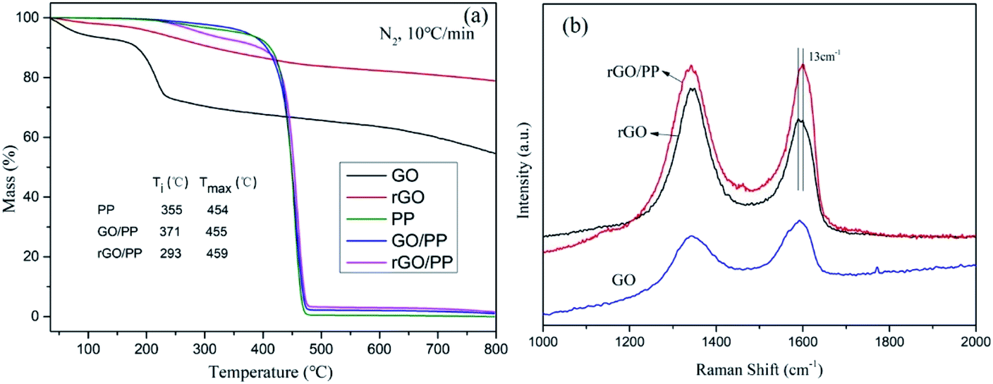 | ||
| Fig. 4 (a) TGA curves of GO, rGO, PP, GO/PP and rGO/PP composites (Φ = 1.5 wt%), Ti and Tmax represent the initial degradation temperature where 5 wt% mass loss occurs, and the maximum mass loss temperature where maximum loss rate takes place; (b) Raman spectra of GO, rGO and the rGO/PP composite (Φ = 1.5 wt%). | ||
The TGA curves of PP, GO/PP and rGO/PP composites are found to have evident weight loss in the range between 230 and 400 °C, which may be attributed to the loss of oxygen-containing groups on the GO/rGO nanosheets and the residual emulsifiers. In addition, it can be clearly seen that the initial weight loss by thermal degradation is accelerated in the presence of rGO. Similar phenomenon has also been observed in other polymer nanocomposites of graphene,25 although it is not well understood. We suppose that although rGO nanosheets can act as barriers which hinder the diffusion of volatile decomposition products, the introduction of rGO could improve the thermal conduction of the composites, which may be a cause of this promoted thermal degradation.
Raman spectroscopy was also conducted to characterize the structural changes occurring in GO and rGO and further confirm the strong interaction between the rGO nanosheets and PP latex particles. The Raman spectrum features a D band at 1345 cm−1 (the structural defects of graphite) and a G peak at 1590 cm−1 (the in-plane vibration adsorption of sp2 graphitic structure). As shown in Fig. 4b, the D/G intensity ratio (ID/IG) of rGO (ID/IG = 1.40) is larger than that of GO (ID/IG = 0.68), reflecting a decrease in the size of the sp2 domains and an increase in the degree of disorder upon the reduction of GO, which is typical in GO and reduced graphene.26 However, compared to rGO, a decreased of ID/IG of rGO/PP composite (ID/IG = 1.01) is observed, indicating that the reduction degree of rGO in the rGO/PP composite (Φ = 1.5 wt%) is smaller than that of rGO without the presence of PP latex. This indicates that the presence of the PP latex gives rise to a slight decrease in the reduction efficiency of GO nanosheets, which is consistent with the report of Wang et al.21 In addition, by comparing the G-peak position of rGO and rGO/PP composite, it can be seen the G-peak position of the rGO/PP composite is stiffened (i.e., shifted to higher frequency) by about 13 cm−1. The blue shift of G peak suggests that a strong interface interaction exists between the rGO nanosheets and PP latex particles.27
Dielectric properties of the rGO/PP composites
The dielectric constant, dielectric loss and AC conductivity of PP and rGO/PP composites as a function of frequency at room temperature are shown in Fig. 5. It can be clearly observed from Fig. 5a that at lower rGO content (Φ = 0.5 wt%), the dielectric constant of the rGO/PP composite exhibits a slow decrease trend along with the increasing frequency, similarly to that of PP. As the rGO content increased (Φ = 1 and 1.5 wt%), the dielectric constant of the rGO/PP composites largely decreases with the increase in frequency, indicating a strong frequency dependence of the dielectric constant. The strong frequency dependence of the dielectric constant in the low-frequency range is dominated by the interfacial polarization effect (also known as Maxwell–Wagner–Sillars (MWS) effect) of rGO nanosheets on PP molecules because the micro-capacitor structure model is frequency-independent, as reported in previous studies.28 In addition, in this study, the parallel micro-capacitor structure in the composites is difficult to form because of the encapsulating of rGO on spherical PP latex particles. The MWS effect is ascribed to the accumulation of many charge carriers at the internal interfaces between the rGO and PP.29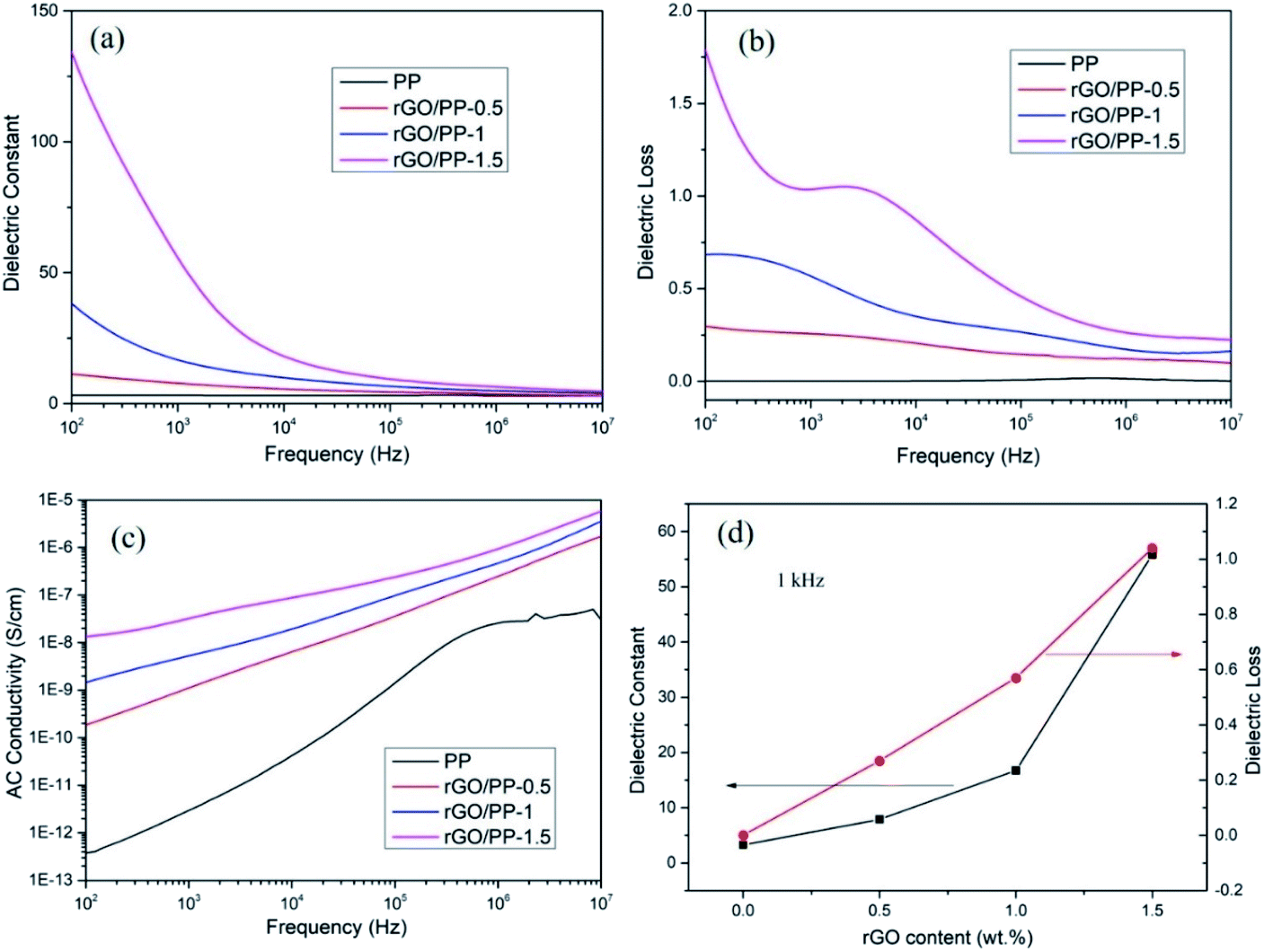 | ||
| Fig. 5 Frequency response of (a) dielectric constant, (b) dielectric loss, (c) AC conductivity of the rGO/PP composites measured at room temperature, (d) the dielectric constant and dielectric loss of PP composites as a function of rGO concentration at 1 kHz. | ||
The dielectric constant of the rGO/PP composites can be enhanced by introducing rGO nanosheets into PP matrix (see in Fig. 5a). The detailed values of the dielectric constant of PP and rGO/PP composites at 1 kHz are summarized in Fig. 5d. We can observe that the dielectric constant at 1 kHz obviously increases from 3.28 for PP to 7.87 with 0.5 wt% of rGO, and then sharply increases to 16.74 and 55.8 for the composite with 1 wt% and 1.5 wt% of rGO, respectively. Comparing with PP, the desired dielectric constant of about 50 is obtained with the presence of 1.5 wt% of rGO, indicating that rGO/PP composite with high dielectric constant at a low filler content has been obtained by the formation of segregated network structure and the moderate reduction in GO nanosheets.
The dielectric loss is commonly used as a measure of the energy dissipation in a dielectric material. In the practical application of high-dielectric-constant polymer composites, low dielectric loss is highly desirable and has been actively pursued. The dielectric loss of PP and rGO/PP composites is shown in Fig. 5b. We can observe that the dielectric loss of the composite at a low content (0.5 wt%) of rGO is at a very low level (<0.5) at all frequencies, similarly to that of PP. Even for the composite with 1.5 wt% of rGO, the dielectric loss only slightly increases (<1.5). The dielectric loss is mainly regarded as the contribution of three sections: conduction loss, dipole loss and interfacial polarization related loss.30 It is well known that conduction loss arises from high DC conductance caused by the direct connection between conductive fillers, as reported in many studies.31 The AC conductivity of all the rGO/PP composites increases with increasing frequency in the measured frequency ranges, indicating a strong frequency dependence of AC conductivity because of the hopping and tunneling mechanism32 (see in Fig. 5c), which can be ascribed to their insulating nature.33 Therefore, the low dielectric loss of rGO/PP composites is mainly attributed to the low conduction loss. In this study, the moderate reduction in GO nanosheets retains a low leakage current, leading to the low dielectric loss of the rGO/PP composites.
The mechanism for the preparation of rGO/PP composites with high dielectric constant and low dielectric loss at a low filler content is proposed as follows. Both the interfacial polarization ability and the spatial distribution of conductive fillers are the key factors to affect the dielectric performance.34 The segregated network structure was formed by the self-assembled encapsulation of GO nanosheets on PP latex particles during emulsification and encapsulation of rGO nanosheets on PP latex particles during the reduction in GO due to the strong interaction between them. The partial π–π restoration of graphene structure by in situ moderate reduction using hydrazine hydrate leads to the significant increase in interfacial polarization ability of rGO, and thus significantly increases the dielectric constant of rGO/PP composites. Meanwhile, the moderate reduction in GO nanosheets results in a low leakage current, and thus maintains low dielectric loss of the rGO/PP composites.
The breakdown strength (Eb), which is defined as the maximum electric field that a dielectric can withstand without losing its insulating properties, is another important parameter benchmarking the dielectric performances of dielectrics. The breakdown strength determines the operating electric field and together with the dielectric constant determines the maximum energy storage density of the dielectric materials. The breakdown strengths of the PP and rGO/PP composites with rGO contents of 0.5, 1 and 1.5 wt% were measured as 84, 63, 46 and 27 kV mm−1, respectively. With increasing the content of rGO, the breakdown strength of the composites decreases, though the dielectric constant increases.
Theoretically, the maximum energy storage density (Wmax: J cm−3) of the linear dielectric is dependent on the dielectric constant and the breakdown strength as follows,35
 | (1) |
Conclusions
rGO/PP dielectric composites with high dielectric constant and low dielectric loss at a low filler content were prepared via constructing a segregated moderately reduced graphene network by encapsulating of GO nanosheets on PP latex particles and the in situ reduction in GO nanosheets by hydrazine hydrate. GO/PP latex was prepared through artificial PP latex preparation in the presence of GO based on solution-emulsification technique. As the emulsification proceeded, GO can self-assemble to encapsulate on PP latex particles because of the hydrogen bonding interaction between PP-g-MA and GO, and after reduction, the rGO encapsulated PP latex particles were obtained. TGA results show that the introduction of rGO has a slightly negative effect on the thermal stability of the composites. The formation of a segregated graphene network at a low content of rGO and the partial π–π restoration of graphene structure resulted in a high dielectric constant. The moderate reduction in GO nanosheets retains a low dielectric loss and relatively high breakdown strength of the rGO/PP composites. Dramatically enhanced dielectric constant and relatively high breakdown strength result in the increase in the maximum energy storage density, which is desirable to capacitors for energy storage.Conflicts of interest
There are no conflicts to declare.Acknowledgements
This work was supported by the Natural Science Foundation of Shandong Province (project No. ZR2020QE072).Notes and references
- X. Huang and P. Jiang, Adv. Mater., 2015, 27, 546–554 CrossRef CAS PubMed
.
- J. Yang, X. Zhu, H. Wang, X. Wang, C. Hao, R. Fan, D. Dastan and Z. Shi, Composites, Part A, 2020, 131, 105814 CrossRef CAS
- G. M. Joshi, S. M. Khatake, S. Kaleemulla, N. M. Rao and T. Cuberes, Curr. Appl. Phys., 2011, 11, 1322–1325 CrossRef
- M. Li, Y. Deng, Y. Wang, Y. Zhang and J. Bai, Mater. Chem. Phys., 2013, 139, 865–870 CrossRef CAS
- A. Ameli, M. Nofar, C. B. Park, P. Pötschke and G. Rizvi, Carbon, 2014, 71, 206–217 CrossRef CAS
- H. Wu, P. Yao, N. Ning, L. Zhang, H. Tian, Y. Wu and M. Tian, RSC Adv., 2016, 6, 32932–32939 RSC
- M. Monti, M. Zaccone, A. Frache, L. Torre and I. Armentano, Nanomaterials, 2021, 11(2), 550 CrossRef CAS PubMed
- C.-Y. Lee and C.-W. Chang, J. Compos. Sci., 2021, 5, 52 CrossRef CAS
- Z. M. Dang, M. S. Zheng and J. W. Zha, Small, 2016, 12, 1688–1701 CrossRef CAS PubMed
- C.-Q. Li, J.-W. Zha, H.-Q. Long, S.-J. Wang, D.-L. Zhang and Z.-M. Dang, Compos. Sci. Technol., 2017, 153, 111–118 CrossRef CAS
- O. Regev, P. N. B. ElKati, J. Loos and C. E. Koning, Adv. Mater., 2004, 16, 248–251 CrossRef CAS
- E. Tkalya, M. Ghislandi, A. Alekseev, C. Koning and J. Loos, J. Mater. Chem., 2010, 20, 3035 RSC
- G. George, S. M. Simon, V. P. Prakashan, M. S. Sajna, M. Faisal, R. Wilson, A. Chandran, P. R. Biju, C. Joseph and N. V. Unnikrishnan, RSC Adv., 2018, 8, 30412–30428 RSC
- H. Pang, L. Xu, D.-X. Yan and Z.-M. Li, Prog. Polym. Sci., 2014, 39, 1908–1933 CrossRef CAS
- R. Hong, Z. Zhao, J. Leng, J. Wu and J. Zhang, Composites, Part B, 2019, 176, 107214 CrossRef CAS
- F. E. Alam, J. Yu, D. Shen, W. Dai, H. Li, X. Zeng, Y. Yao, S. Du, N. Jiang and C. T. Lin, Polymers, 2017, 9(12), 662 CrossRef PubMed
- Y. Zhan, M. Lavorgna, G. Buonocore and H. Xia, J. Mater. Chem., 2012, 22, 10464 RSC
- Y. Lin, S. Liu, J. Peng and L. Liu, Compos. Sci. Technol., 2016, 131, 40–47 CrossRef CAS
- H. He, J. Klinowski, M. Forster and A. Lerf, Chem. Phys. Lett., 1998, 287, 53–56 CrossRef CAS
- C. Wu, X. Huang, G. Wang, X. Wu, K. Yang, S. Li and P. Jiang, J. Mater. Chem., 2012, 22, 7010 RSC
- D. Wang, X. Zhang, J.-W. Zha, J. Zhao, Z.-M. Dang and G.-H. Hu, Polymer, 2013, 54, 1916–1922 CrossRef CAS
- J.-J. Lin, M.-Y. Young, S.-M. Shau and I. J. Cheng, Polymer, 2000, 41, 2405–2417 CrossRef CAS
- C. N. R. Rao, K. Biswas, K. S. Subrahmanyam and A. Govindaraj, J. Mater. Chem., 2009, 19, 2457 RSC
- M. Tian, J. Zhang, L. Zhang, S. Liu, X. Zan, T. Nishi and N. Ning, J. Colloid Interface Sci., 2014, 430, 249–256 CrossRef CAS PubMed
- A. V. Raghu, Y. R. Lee, H. M. Jeong and C. M. Shin, Macromol. Chem. Phys., 2008, 209, 2487–2493 CrossRef CAS
- S. Jiang, Z. Gui, C. Bao, K. Dai, X. Wang, K. Zhou, Y. Shi, S. Lo and Y. Hu, Chem. Eng. J., 2013, 226, 326–335 CrossRef CAS
- M.-C. Hsiao, S.-H. Liao, Y.-F. Lin, C.-A. Wang, N.-W. Pu, H.-M. Tsai and C.-C. M. Ma, Nanoscale, 2011, 3, 1516 RSC
- F. He, S. Lau, H. L. Chan and J. Fan, Adv. Mater., 2009, 21, 710–715 CrossRef CAS
- X. Xia, Y. Wang, Z. Zhong and G. J. Weng, Carbon, 2017, 111, 221–230 CrossRef CAS
- L. Xie, X. Huang, C. Wu and P. Jiang, J. Mater. Chem., 2011, 21, 5897 RSC
- X. Zhi, Y. Mao, Z. Yu, S. Wen, Y. Li, L. Zhang, T. W. Chan and L. Liu, Composites, Part A, 2015, 76, 194–202 CrossRef CAS
- N. Yousefi, X. Sun, X. Lin, X. Shen, J. Jia, B. Zhang, B. Tang, M. Chan and J. K. Kim, Adv. Mater., 2014, 26, 5480–5487 CrossRef CAS PubMed
- M. Monti, I. Armentano, G. Faiella, V. Antonucci, J. M. Kenny, L. Torre and M. Giordano, Compos. Sci. Technol., 2014, 96, 38–46 CrossRef CAS
- N. Ning, X. Bai, D. Yang, L. Zhang, Y. Lu, T. Nishi and M. Tian, RSC Adv., 2014, 4, 4543–4551 RSC
- Y. Wang, L. Wang, Q. Yuan, J. Chen, Y. Niu, X. Xu, Y. Cheng, B. Yao, Q. Wang and H. Wang, Nano Energy, 2018, 44, 364–370 CrossRef CAS
| This journal is © The Royal Society of Chemistry 2021 |