 Open Access Article
Preparation of hollow tubular TpBD COF and pod-like ZIF-8/H-TpBD COF tubes using a porous anodic aluminum oxide membrane as template†
Jiayuan He‡
a,
Rijian Mo‡bc,
Guangzheng Jianga,
Lei Hec,
Chunxia Zhouab,
Zhong-Ji Qianbc,
Pengzhi Hong*ab and
Chengyong Li *bc
*bc
aCollege of Food Science and Technology, Guangdong Ocean University, Zhanjiang 524088, China
bShenzhen Institute of Guangdong Ocean University, Shenzhen, Guangdong 518114, China. E-mail: hongpz@gdou.edu.cn; cyli@gdou.edu.cn
cSchool of Chemistry and Environment, Guangdong Ocean University, Zhanjiang 524088, China
First published on 29th November 2021
Abstract
By sacrificing a porous anodic aluminum oxide (AAO) membrane as a template, hollow tubular TpBD (H-TpBD) covalent organic framework (COF) tubes were synthesized in situ and zeolitic imidazolate framework (ZIF-8) nanoparticles were creatively synthesized in situ in H-TpBD tubes at room temperature. H-TpBD COF tubes and ZIF-8/H-TpBD COF tubes were procured by using a strong base or acid to remove the AAO membrane. Then they were analyzed by X-ray diffraction, Fourier infrared spectroscopy, scanning electron microscope, transmission electron microscope, etc. Surprisingly, the obtained TpBD COF has a very small aperture (1.8 nm), thinner tube thickness (50 nm), high stability, and a smooth and homogeneous surface. And the pod-like ZIF-8/H-TpBD COF with complete tubular structure was also obtained.
Covalent organic frameworks (COFs) are a class of crystalline organic porous materials formed by connecting organic units (consisting of light atoms such as C, H, O, and N) through chemical covalent bonds, and have atomically precise porous framework structures. COF polymers can be predesigned and synthesized by topology-diagram-directed polymer development.1 The key to obtaining polymers with predesigned primary and higher-order structures is to fuse covalent bonds and non-covalent interactions into a polymer system to form a first-order structure with a specific structure or chain segment, thus guiding the formation of higher-order structures. The COF, with the covalent bond and non-covalent interaction in the polymerization system, has the characteristics of this kind of polymer. And in order to be suitable for a particular field, COF-derived materials can also be prepared by forming composites and high-temperature pyrolysis.2 In addition, due to its unique characteristics, such as nano pore-size (usually ranging from several angstroms to several nanometers),3 ordered channel structure, excellent thermal stability, and excellent chemical properties, COF has attracted great attention in many fields, including separation,4 catalysis,5,6 energy storage,7 and medicine delivery.8,9
Some studies have found that COF with hollow nanostructures carry the characteristics of low density, high specific surface area, and strong load capacity. So hollow-structured COF materials have gained a lot of attention in recent years. And the hollow COF got broad application prospects in the fields of environmental protection,10,11 biomedicine,12,13 membrane separation,14 and food safety.15,16 Gole et al. reported a hollow imine COF tube formed by s bottom-up microtubular self-assembly, with a mean diameter of about 150 nm.17 However, the machinability of conventional self-assembled COFs is very challenging. Without spatial and temporal control of the nucleation and growth, COFs are always separated into insoluble and cannot processable solids.9 Huang et al. prepared hollow nanotubes by selectively hydrolyzing the target covalent bond in the two-dimensional hetero-pore COF.18 Although it can be synthesized by self-assembly, by self-assembly, the synthesis of hollow structures by templates provides significant advantages in terms of size and shape control and freedom of template variability.19 Hollow 1,3,5-triformylphloroglucinol/p-phenylenediamine (TpPa) COF nanostructures were synthesized with template-assisted method. ZnO@TpPa is formed with ZnO nanorods as the core, and then the ZnO nanorods are removed to obtain a hollow TpPa COF nanostructure, which has a capsule-like morphology. Nevertheless, the synthesis of nanosized low-density hollow COF tubes remains a challenge.20
Here, tubular and pod-like COF structures were synthesized using a porous anodic aluminum oxide (AAO) membrane as a template. AAO membrane was prepared subject to the literature prepared by a two-step anodic oxidation method and with a pore size of 200 nm.21 The 1,3,5-triformylphloroglucinol (Tp) and benzidine (BD) were used as reaction solvents to form a TpBD COF tubular structure in AAO by in situ growth method. 3 M NaOH solution was used to remove the AAO membrane to obtain a hollow tubular TpBD COF that has the characteristics of rich hydrophilic groups and high stability22 (Scheme 1(a), a more detailed explanation can be seen in the ESI†). Firstly, imines were formed on the template by continuous mutual conversion inter-conversion from enol to keto forms, and then the network tubular skeleton of polyimines was formed by precipitation polymerization of TP and BD under the condition of equilibrium control of the template. The obtained polymer is amorphous in structure, has inherent imine bonds and internal dynamic imine exchange process, which can initiate the structural transition from disorder to order.23 Analogously, zeolitic imidazolate framework (ZIF-8, a highly porous crystalline solid based on the coordination of organic 2-methylimidazole (2-mIM) ligand and Zn2+ ionic subunit)24 was formed in TpBD COF/AAO by in situ growth method using zinc nitrate and dimethylimidazole as reaction reagents. Finally, the pod-like structure of the ZIF-8/H-TpBD COF tube can be obtained by treatment with 20 μL of 1% hydrofluoric acid (HF) for 30 seconds and ultrasonication to remove AAO (Scheme 1(b), a more detailed explanation can be seen in the ESI†). The combination of ZIF-8 and COF tube is designed to better integrate the strengths of both sides. Meanwhile, contrasted with other methods, the size of the synthesized COF tube is adjustable using the AAO nanochannel as a template. With the AAO nanochannel as the template, the size of the synthesized COF tubes can be adjusted and a pod-like COF tube can be synthesized. This provides a new method for the synthesis of COF tubes.
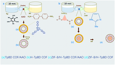 | ||
| Scheme 1 Synthesis of H-TpBD COF nanotubes and ZIF-8/TpBD COF peapod composite. (a) H-TpBD COF nanotubes (b) ZIF-8-TpBD COF. | ||
The reaction time of Tp and BD plays an indispensable role in the synthesis of TpBD COF/AAO nanotubes. Fig. 1 and S1† reveal scanning electron microscope (SEM) images of TpBD/AAO synthesized at different reaction times (1–8 hours). When the reaction time of Tp and BD is fewer than 5 hours, almost no COF tube is formed in the AAO nanochannel. Remarkably, when the reaction time was extended to 5 hours in Fig. 1(e), TpBD COF/AAO tubular structures started to mature in the AAO nanochannels. It shows that when the reaction time is 1–5 hours, it is the transition process of TpBD aggregation network structure from disorder to order. Furthermore, when the reaction time was extended from 5 to 8 hours (Fig. S1†), the shape of the COF nanotubes in the AAO nanochannels did not change with the increase of the reaction time, but grew along the vertical direction of the AAO membrane hole. And it extends outwards during growth, while preserving a complete tubular structure. Although it looks very disorderly. Obviously, the COF tubes grew along the pores of AAO membrane, namely, the AAO membrane is used as the template to extend to the direction of the pore channel to form nanotubes. Through comparison, it can be found that with the increase of reaction time, the number of COF tubes gradually reduced and the length of tubes also increased significantly (Fig. S1†).
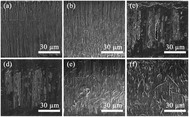 | ||
| Fig. 1 SEM images of TpBD COF/AAO membrane synthesized by Tp and BD under different reaction times. (a) 1 h. (b) 2 h. (c) 3 h. (d) 4 h. (e) 5 h. (f) 6 h. | ||
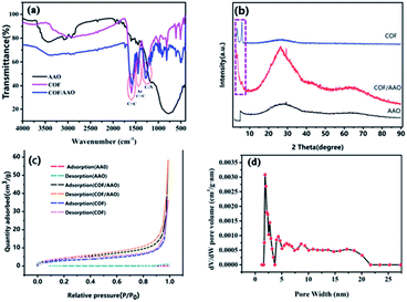
FT-IR spectroscopy was used to characterize the prepared samples to verify the formation of TpBD COF/AAO tubes in the AAO membrane. As shown in Fig. 2(a), the TpBD COF/AAO have appeared characteristic peaks at 1595, 1465 and 1259 cm−1 correspond to the C![[double bond, length as m-dash]](https://www.rsc.org/images/entities/char_e001.gif) C, Ar (C
C, Ar (C![[double bond, length as m-dash]](https://www.rsc.org/images/entities/char_e001.gif) C), and C–N of the TpBD respectively. Which is consistent with the literature report. The spectrum showed that the C
C), and C–N of the TpBD respectively. Which is consistent with the literature report. The spectrum showed that the C![[double bond, length as m-dash]](https://www.rsc.org/images/entities/char_e001.gif) N peak disappeared, and a new C
N peak disappeared, and a new C![[double bond, length as m-dash]](https://www.rsc.org/images/entities/char_e001.gif) C peak appeared at 1595 cm−1,25,26 illustrating the effectively formation of TpBD. Compared with pure AAO, at the wavenumber range of 500 to 4000 cm−1 that the infrared spectrum of TpBD COF/AAO has the same characteristic peaks (1595, 1465 and 1259 cm−1) as TpBD COF. But there is no characteristic peak in pure AAO film, as shown in the Black Line in Fig. 2(a). The above analysis confirms that the TpBD COF/AAO has been successfully formed in nanochannels of AAO membrane. To eliminate internal stress and make the crystal structure of COF more uniform through grain reconstruction, TpBD nanotubes were annealed at 800 °C. As shown in Fig. 2(b), XRD spectrum of TpBD/AAO presents moderate crystallinity, exhibiting the first 2θ peak at low angles of 3.3°, corresponding to the (100) reflection plane.22
C peak appeared at 1595 cm−1,25,26 illustrating the effectively formation of TpBD. Compared with pure AAO, at the wavenumber range of 500 to 4000 cm−1 that the infrared spectrum of TpBD COF/AAO has the same characteristic peaks (1595, 1465 and 1259 cm−1) as TpBD COF. But there is no characteristic peak in pure AAO film, as shown in the Black Line in Fig. 2(a). The above analysis confirms that the TpBD COF/AAO has been successfully formed in nanochannels of AAO membrane. To eliminate internal stress and make the crystal structure of COF more uniform through grain reconstruction, TpBD nanotubes were annealed at 800 °C. As shown in Fig. 2(b), XRD spectrum of TpBD/AAO presents moderate crystallinity, exhibiting the first 2θ peak at low angles of 3.3°, corresponding to the (100) reflection plane.22
In order to evaluate the porosity of the as-synthesized TpBD COF nanotube, we have collected the N2 adsorption isotherms of the AAO, TpBD COF/AAO and TpBD COF nanotube. As shown in Fig. 2(c), the N2 adsorption analyses performed for TpBD COF/AAO, which is characteristic of microporous materials.22,26 The surface area of TpBD COF nanotube, TpBD/AAO membrane and AAO membrane was calculated using the BET model. The increased surface area of H-TpBD COF nanotube (11.37 m2 g−1) and TpBD COF/AAO (15.21 m2 g−1) as compared to AAO (4.51 m2 g−1) confirms the removal of AAO, leaving behind the TpBD COF nanotube. The pore size distribution of TpBD COF nanotube calculated related to the BET model shows that the pore size of TpBD COF nanotube is primarily clustered at 1.8 nm in Fig. 2(d).
In order to obtain the tubular TpBD COF structure, the AAO template must be removed from the TpBD COF/AAO. 5 M NaOH solution was exploited to remove AAO. Scanning electron microscope (SEM) and transmission electron microscope (TEM) were used to characterize the obtained TpBD COF tube, as shown in Fig. 3. Remarkably, the TpBD COF after removing the AAO is a tubular structure, and the tube length can be extended to 60 μm. Of course, the length of the COF tubes will be inconsistent due to the difference in reaction time or reaction position. In addition, most COF tubes are clustered together. After sonication, individual COF tubes or shorter COF tubes can be obtained (Fig. S2†). As shown in Fig. 3(c) and (d), it can be found that the COF tube is a hollow tube and its surface is smooth and uniform. The time and average diameter distribution diagram are shown in Fig. S3.† With the change of reaction time of TP and BD, the diameter of the synthetic COF tube also changes, and when the reaction time is 6 hours, the diameter reaches the maximum. Fig. S4† shows that the inner and outer diameter is mainly distributed at 160 nm and 211 nm, respectively. Hence the thickness of the tube wall is about 50 nm. After that, as the reaction time increases, the diameter of the tube gradually decreases after 8 hours. It may be due to the increase of tubular structure, which leads to the enhancement of the π–π stacking effect and restrict the extension of pipe diameter.
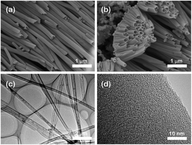 | ||
| Fig. 3 Morphological characterization of TpBD COF nanotubes. (a) and (b) SEM images, (c) TEM image, and (d) HRTEM image of H-TpBD COF nanotubes. | ||
Furthermore, we also synthesized ZIF-8/H-TpBD COF that ZIF-8 are grew in the TpBD COF/AAO tube. The pod-like structure of the ZIF-8/H-TpBD COF tube can be obtained by treatment with 20 μL of 1% hydrofluoric acid for 30 seconds and ultrasonication to remove AAO. Fig. 4 are the TEM images of ZIF-8/H-TpBD COF/AAO, including cross-section view and overview of ZIF-8 in the COF tube. It can be found that the COF tube is filled with ZIF-8 but still preserves a hollow tube structure, while the ZIF-8 is evenly distributed in the tube. Combining the ZIF-8 structure into the H-TpBD COF tube is an innovative idea in this article, which entirely utilizes the space of the COF tube. In order to verify the practicability of the synthetic materials, the adsorption of tetracycline in water by H-TpBD COF and ZIF-8/H-TpBD COF were performed. The adsorption capacity of H-TpBD COF and ZIF-8/H-TpBD COF are 2.97 mg mg−1 and 4.17 mg mg−1 (Fig. 5), respectively. Compared with the reference, the H-TpBD/COF and ZIF/H-TpBD/COF have the great potential application in environmental protection (a more detailed explanation can be seen in the ESI†).27
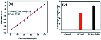 | ||
| Fig. 5 (a) The linear range of tetracycline. (b) The adsorption capacity of tetracycline by H-TpBD COF and ZIF-8/H-TpBD COF. | ||
In summary, using porous AAO membrane as a template, we innovatively synthesized H-TpBD COF and the in situ generated pod-like ZIF-8 COF structures. The H-TpBD COF has an inner and outer diameter of 160 nm and 211 nm, and the ultrathin thickness of pipe of about 50 nm. The ZIF-8 particles are distributed in the tubular TpBD COF without damaging the integrity of the H-TpBD COF tubes. Combining ZIF-8 with COF with stable structure to better integrate the advantages of both parties is the latest highlight of this article. It is also believed that this will be one of the important directions for further research on polycrystalline polymer materials. These materials show great potential to be applied to the fields of separation, catalysis, environmental protection, and food safety.
Author contributions
Jiayuan He: conceptualization, writing–original draft, writing–review & editing. Rijian Mo: investigation, formal analysis. Guangzhneg Jiang: collect the samples. Lei He: collect the samples. Chunxia Zhou: collect the samples. Zhong-Ji Qian: investigation, formal analysis. Pengzhi Hong: conceptualization, funding acquisition. Chengyong Li: supervision, project administration, funding acquisition.Conflicts of interest
The authors declare that they have no known competing financial interests or personal relationships that could have appeared to influence the work reported in this paper.Acknowledgements
This work was supported by National Natural Science Foundation of China (21874029), Guangdong Basic and Applied Basic Research Foundation (2021A1515010291), Project of Enhancing School with Innovation of Guangdong Ocean University (2020ZDZX2029), Shenzhen Science and Technology R&D Fund (KCXFZ202002011011057), Special Funds for Science Technology Innovation and Industrial Development of Shenzhen Dapeng New District (KJYF202001-06, PT202001-18).Notes and references
- I. Ahmed and S. H. Jhung, Coord. Chem. Rev., 2021, 441, 213989 CrossRef CAS.
- K. Geng, V. Arumugam, H. Xu, Y. Gao and D. Jiang, Prog. Polym. Sci., 2020, 108, 8814–8933 CrossRef.
- R.-R. Liang, A. Ru-Han, S.-Q. Xu, Q.-Y. Qi and X. Zhao, J. Am. Chem. Soc., 2020, 142, 70–74 CrossRef CAS PubMed.
- J. L. Fenton, D. W. Burke, D. Qian, M. O. de la Cruz and W. R. Dichtel, J. Am. Chem. Soc., 2021, 143, 1466–1473 CrossRef CAS PubMed.
- J.-C. Wang, C.-X. Liu, X. Kan, X.-W. Wu, J.-L. Kan and Y.-B. Dong, Green Chem., 2020, 22, 1150–1155 RSC.
- G. C. Dubed Bandomo, S. S. Mondal, F. Franco, A. Bucci, V. Martin-Diaconescu, M. A. Ortuño, P. H. van Langevelde, A. Shafir, N. López and J. Lloret-Fillol, ACS Catal., 2021, 11, 7210–7222 CrossRef CAS.
- M. Yu, N. Chandrasekhar, R. K. M. Raghupathy, K. H. Ly, H. Zhang, E. Dmitrieva, C. Liang, X. Lu, T. D. Kuehne, H. Mirhosseini, I. M. Weidinger and X. Feng, J. Am. Chem. Soc., 2020, 142, 19570–19578 CrossRef CAS PubMed.
- L.-G. Ding, S. Wang, B.-J. Yao, F. Li, Y.-A. Li, G.-Y. Zhao and Y.-B. Dong, Adv. Healthcare Mater., 2021, 10, 2001821 CrossRef CAS PubMed.
- H. S. Sasmal, A. Halder, S. Kunjattu, K. Dey, A. Nadol, T. G. Ajithkumar, P. R. Bedadur and R. Banerjee, J. Am. Chem. Soc., 2019, 141, 20371–20379 CrossRef CAS PubMed.
- Y. Ying, A. M. Pourrahimi, Z. Sofer, S. Matejkova and M. Pumera, ACS Nano, 2019, 13, 11477–11487 CrossRef CAS PubMed.
- L. Wang, Y. Yang, H. Liang, N. Wu, X. Peng, L. Wang and Y. Song, J. Hazard. Mater., 2021, 409, 124528 CrossRef CAS PubMed.
- M. Li, S. Qiao, Y. Zheng, Y. H. Andaloussi, X. Li, Z. Zhang, A. Li, P. Cheng, S. Ma and Y. Chen, J. Am. Chem. Soc., 2020, 142, 6675–6681 CrossRef CAS PubMed.
- T. Huo, Y. Yang, M. Qian, H. Jiang, Y. Du, X. Zhang, Y. Xie and R. Huang, Biomaterials, 2020, 260, 120305 CrossRef CAS PubMed.
- Y. Liu, H. Wu, S. Wu, S. Song, Z. Guo, Y. Ren, R. Zhao, L. Yang, Y. Wu and Z. Jiang, J. Membr. Sci., 2021, 618, 118693 CrossRef CAS.
- X.-X. Wang, L. Liu, X.-L. Wang, G.-J. Xu, R.-S. Zhao, M.-L. Wang, J.-M. Lin and X. Wang, Food Chem., 2021, 361, 130018 CrossRef CAS PubMed.
- Y. Lu, Y. Liang, Y. Zhao, M. Xia, X. Liu, T. Shen, L. Feng, N. Yuan and Q. Chen, ACS Appl. Mater. Interfaces, 2021, 13, 1644–1650 CrossRef CAS PubMed.
- B. Gole, V. Stepanenko, S. Rager, M. Gruene, D. D. Medina, T. Bein, F. Wuerthner and F. Beuerle, Angew. Chem., Int. Ed., 2018, 57, 846–850 CrossRef CAS PubMed.
- L. Huang, L. Ao, W. Wang, D. Hu, Z. Sheng and W. Su, Chem. Commun., 2015, 51, 3923–3926 RSC.
- G. Das, T. Skorjanc, S. K. Sharma, F. Gandara, M. Lusi, D. S. S. Rao, S. Vimala, S. K. Prasad, J. Raya, D. S. Han, R. Jagannathan, J.-C. Olsen and A. Trabolsi, J. Am. Chem. Soc., 2017, 139, 9558–9565 CrossRef CAS PubMed.
- P. Pachfule, S. Kandmabeth, A. Mallick and R. Banerjee, Chem. Commun., 2015, 51, 11717–11720 RSC.
- R. Mo, L. He, C. Zhou, Z.-J. Qian, P. Hong, S. Sun, Z. Wang, Y. Wang and C. Li, Anal. Chem., 2019, 91, 8184–8191 CrossRef CAS PubMed.
- H. Yang, X. Cheng, X. Cheng, F. Pan, H. Wu, G. Liu, Y. Song, X. Cao and Z. Jiang, J. Membr. Sci., 2018, 565, 331–341 CrossRef CAS.
- J. Tan, S. Namuangruk, W. Kong, N. Kungwan, J. Guo and C. Wang, Angew. Chem., Int. Ed., 2016, 55, 13979–13984 CrossRef CAS PubMed.
- S. K. Alsaiari, S. S. Qutub, S. Sun, W. Baslyman, M. Aldehaiman, M. Alyami, A. Almalik, R. Halwani, J. Merzaban, Z. Mao and N. M. Khashab, Sci. Adv., 2021, 7, eabe7174 CrossRef CAS PubMed.
- C.-X. Yang, C. Liu, Y.-M. Cao and X.-P. Yan, Chem. Commun., 2015, 51, 12254–12257 RSC.
- B. P. Biswal, S. Chandra, S. Kandambeth, B. Lukose, T. Heine and R. Banerjee, J. Am. Chem. Soc., 2013, 135, 5328–5331 CrossRef CAS PubMed.
- H. R. Nodeh and H. Sereshti, RSC Adv., 2016, 6, 89953–89965 RSC.
Footnotes |
| † Electronic supplementary information (ESI) available. See DOI: 10.1039/d1ra06062g |
| ‡ These authors have contributed equally to this work and share first authorship. |
| This journal is © The Royal Society of Chemistry 2021 |

