
 Open Access Article
 This Open Access Article is licensed under a Creative Commons Attribution-Non Commercial 3.0 Unported Licence
A universal electrochemical lithiation–delithiation method to prepare low-crystalline metal oxides for high-performance hybrid supercapacitors†
Zhuo-Dong Wu a,
De-Jian Chenb,
Long Lib and
Li-Na Wang*c
a,
De-Jian Chenb,
Long Lib and
Li-Na Wang*c
aSchool of Artificial Intelligence, Nanjing University of Information Science and Technology, Nanjing 210044, China. E-mail: 201883270171@nuist.edu.cn
bCollege of Physical Science and Technology, Central China Normal University, Wuhan 430079, China
cSchool of Artificial Intelligence, Nanjing University of Information Science and Technology, Nanjing 210044, China. E-mail: wangllna@163.com
First published on 13th September 2021
Abstract
The electrochemical performance of transition metal oxides (TMOs) for hybrid supercapacitors has been optimized through various methods in previous reports. However, most previous research was mainly focused on well-crystalline TMOs. Herein, the electrochemical lithiation–delithiation method was performed to synthesise low-crystallinity TMOs for hybrid supercapacitors. It was found that the lithiation–delithiation process can significantly improve the electrochemical performance of “conversion-type” TMOs, such as CoO, NiO, etc. The as-prepared low-crystallinity CoO exhibits high specific capacitance of 2154.1 F g−1 (299.2 mA h g−1) at 0.8 A g−1, outstanding rate capacitance retention of 63.9% even at 22.4 A g−1 and excellent cycling stability with 90.5% retention even after 10![[thin space (1/6-em)]](https://www.rsc.org/images/entities/char_2009.gif) 000 cycles. When assembled as hybrid supercapacitors using active carbon (AC) as the active material of the negative electrode, the devices show a high energy density of 50.9 W h kg−1 at 0.73 kW kg−1. Another low-crystallinity NiO prepared by the same method also possesses a much higher specific capacitance of 2317.6 F g−1 (302.6 mA h g−1) compared to that for pristine commercial NiO of 497.2 F g−1 at 1 A g−1. The improved energy storage performance of the low-crystallinity metal oxides can be ascribed to the disorder of as-prepared low-crystallinity metal oxides and interior 3D-connected channels originating from the lithiation–delithiation process. This method may open new opportunities for scalable and facile synthesis of low-crystallinity metal oxides for high-performance hybrid supercapacitors.
000 cycles. When assembled as hybrid supercapacitors using active carbon (AC) as the active material of the negative electrode, the devices show a high energy density of 50.9 W h kg−1 at 0.73 kW kg−1. Another low-crystallinity NiO prepared by the same method also possesses a much higher specific capacitance of 2317.6 F g−1 (302.6 mA h g−1) compared to that for pristine commercial NiO of 497.2 F g−1 at 1 A g−1. The improved energy storage performance of the low-crystallinity metal oxides can be ascribed to the disorder of as-prepared low-crystallinity metal oxides and interior 3D-connected channels originating from the lithiation–delithiation process. This method may open new opportunities for scalable and facile synthesis of low-crystallinity metal oxides for high-performance hybrid supercapacitors.
Introduction
Lithium-ion batteries (LIBs) have worked as efficient energy storage devices since the market launch in 1991 due to their high energy density, long lifespan, high safety, and environmental friendliness.1–8 In addition to their prosperous commercial application, the specific lithium-ion insertion–extraction mechanism holds great potential in preparing nanostructured materials for catalysis.9–11 Cui and coworkers switched the charging and discharging status of battery electrodes to precisely control compressive or tensile strain on supported catalysts, with lattice compressed Pt induced by the lithium battery electrode exhibiting 90% enhancement in oxygen reduction reaction (ORR).9 However, to the best of our knowledge, the lithiation–delithiation method has never been used to synthesize advanced energy storage materials of hybrid supercapacitors (SCs).Transition metal oxides (TMOs) play a crucial role in anode materials of LIBs, which can be divided into three types in terms of reaction mechanism: insertion–desertion, alloying, and conversion.1 Conversion reactions are observed in a lot of metal oxides, such as cobalt oxide, nickel oxide, copper oxides, iron oxides and so on.1,5,12–17 “conversion-type” metal oxides have attracted plentiful attention for their facial large-scale fabrication, natural abundance, low cost, and multi-valent states which can provide much higher capacitance than traditional carbon-based materials.6,18,19 Numerous efforts have been devoted to exploring an in-depth understanding of “conversion-type” metal oxides to pursue advanced materials for next-generation batteries.13–16,20,21 Mechanism of “conversion-type” anodes during the charge–discharge process can be represented as eqn (1):14,15
| 2yLi+ + MxOy + 2ye− ↔ yLi2O + xM | (1) |
Despite the “conversion-type” metal oxides have been widely used as anodes in LIBs, however, its energy density and power density are still hindered by the poor conductivity and huge volume expansion. By contrast, Hybrid Supercapacitor Devices (HSDs) which are consisted of a battery-type electrode and capacitive electrode have drawn enormous attention due to their combination of high capacity battery-type electrode and high rate capacitive electrode.25,26 The emergence of HSDs provides a reliable alternative for the next-generation energy storage devices in advantages of high energy density, power density, and cycling durability. The designed battery-type electrodes are of great significance to achieve excellent electrochemical performance.27–29 Strategies to improve battery-type electrodes were mainly focused on (i) fabricating nanostructured metal oxides with desirable architectures with large specific area.30–32 (ii) Preparing composite with conductive materials (conductive polymer and carbonaceous materials etc.).33,34 However, the adopted strategies are still far from fully release the energy storage capacity of those metal oxides. Recently, it has been demonstrated low-crystalline or amorphous structured metal hydroxides/oxyhydroxides show superior electrochemical performance to their well-crystalline counterparts due to their disorder structure.35–42 Firstly, the isotropic nature and absence of grain boundaries provide a self-adaptive strain-relax capacity that can accommodate the volume expansion/contraction during the continuous ion insertion/desertion in the charge–discharge processes, avoiding particle aggregation and pulverization, further resulting in better cycling durability. Secondly, loose arrangement of atoms inside bulk can provide more empty space, which is beneficial for the ion permeation and diffusion, further achieving higher capacitance and rate capacity.43–45 Nevertheless, most previous reported low-crystalline/amorphous architectures for hybrid supercapacitors are based on metal hydroxides/oxyhydroxides rather than metal oxides.
Herein, based on the above statements of the “conversion-type” metal oxides mechanism for LIBs, we propose a facile electrochemical lithium-ion lithiation–delithiation method to prepare low-crystalline metal oxides. The disordered structure can obviously improve the electrochemical performance of the hybrid supercapacitors. When worked as the single electrode for hybrid supercapacitors, as prepared low-crystalline CoO (LCCO) exhibits high specificity of 2154.1 F g−1 (299.2 mA h g−1) at 0.8 A g−1 and outstanding rate capacitance retention of 63.9% at 22.4 A g−1, meanwhile, cycling stability with the capacity retention of 90.5% is kept after 10000 cycles. When assembled as a full hybrid supercapacitor with active carbon as counter electrode, the devices show a high energy density of 50.9 W h kg−1 at the power density of 0.75 kW kg−1. Furthermore, to demonstrate the universality of this lithiation–delithiation method for “conversion-type” metal oxides as hybrid supercapacitors, low-crystalline NiO (LCNO) was further prepared and also possessed a much higher specific capacitance of 2317.6 F g−1 (302.6 mA h g−1) than pristine commercial NiO (CNO) of 497.1 F g−1 at 1 A g−1.
Experimental
Synthesis of low-crystalline metal oxides
The purchased commercial CoO, acetylene black, and poly vinylidene fluoride (PVDF) were added to N-methyl-2-pyrrolidinone (NMP) with the weight ratio of 8:1:1 to form the slurry. Then the slurry was pressed onto cleaned nickel foam which was cut into cycles with a diameter of 12 mm as the working electrode for the lithium battery. The as-prepared electrodes were dried in a vacuum at 80 °C for 12 h. Lithium batteries were assembled in the CR2025 coin cell with the lithium foil as reference electrode and counter electrode in an Ar-filled glove box (model 100 G MBraun, Germany). The electrolyte consisted of 1 M LiPF6 in a mixture of ethylene carbonate (EC)/diethyl carbonate (DEC) (1:1 by volume) was used with a micro-porous polymer membrane separator (Celgard 3501). The Galvanostatic Charge–Discharge (GCD) tests were conducted using an automatic battery testing system (LAND CT2001A model) between 0.01 and 3 V at 50 mA g−1. After presupposed 0, 3, 6, and 15 cycles, the as-prepared working electrodes (donated as LCCO-0, 3, 6, and 15, respectively) were taken out and washed thoroughly with ethanol and deionized water, respectively. After drying at 80 °C overnight, the electrode was directly used for three-electrode system testing. For low-crystalline NiO (LCNO), the synthesis procedure was the same as above LCCO.
Assembly of hybrid supercapacitor
Active carbon (AC) was used as the active material of negative electrode, the slurry containing AC, acetylene black, and PVDF was prepared and pressed on cleaned nickel foam in the same way. Coin cell hybrid supercapacitors were assembled with 2 M KOH as electrolytes. Two-hybrid devices in series were used to light the 2.5 V LED.Characterization and electrochemical measurements
All samples for X-ray diffraction (XRD) and X-ray photoelectron spectroscopy (XPS) measurements were prepared with Cu foil as the current collector. XRD was performed on a Bruker Smart1000 using Cu Kα radiation at a scanning step rate of 0.02° s−1. XPS was performed Kratos Ultra AXIS spectrometer system equipped with a monochromatic Al-Kα source (15 kV). Scanning electron microscopy (SEM) was performed with a field-emission scanning electron microscope (JEOL JSM-6700F). Transmission electron microscopy (TEM) was performed using a field-emission transmission electron microscope (JEOL JEM 2100F, 200 kV).All electrochemical measurements of hybrid supercapacitors including CV, CP, EIS measurements were conducted using a CHI660C electrochemical workstation at room temperature. Individual electrode performance was measured in a three-electrode system with a Pt foil as counter electrode and a Ag/AgCl as reference electrode in 2 M KOH solution.
Results and discussion
A facile and scalable method was developed here to fabricate LCCO/LNCO, the synthesis mechanism and procedures were illustrated in Fig. 1. A nickel foam was selected as the collector, the three-dimensional conducted backbone in Ni form can dramatically increase the mass loading compared with traditional metal foil. Additionally, the 3D conductive backbone can efficiently avoid the separation of a thin film with the collector for the mechanical stress during the packaging of the coin cell. Commercial metal oxides were directly used as precursors to ensure fewer crystal defects and purity during synthesis to avoid the extra influence for the electrochemical performance of metal oxides.46,47 Based on the reduction of crystalline degree and volume expansion effect of conversion-type metal oxides as anodes of LIBs,12,16,20 we control the crystalline and pulverization degree of the low-crystalline metal oxides through changing the cycle numbers in the discharging–charging processes.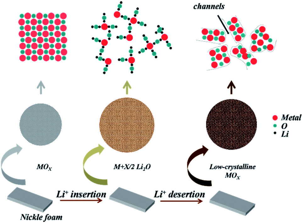 | ||
| Fig. 1 The schematic illustration of fabrication process and formation mechanism of low-crystalline metal oxides. | ||
Li+ reacts with metal oxides when performed with the discharging procedure, then the ultra-small metallic metal particles formed and dispersed in Li2O matrix accompanied with volume expansion. In the following charging process, Li+ was extracted from the compounds, resulting in Li2O decomposition and the oxidation of metal particles, meanwhile, the rebuilt metal oxides preserved the low-crystalline structure.12,16 After above treatment, the electrode was taken out and washed with ethanol and deionized water respectively to remove the organic residents. After drying, the electrode with low-crystalline metal oxides can be directly used for battery-type cathode in hybrid supercapacitors.
Firstly, for CoO, we conducted the charge–discharge process after 0, 3, 6, and 15 cycles (named as LCCO-0, 3, 6, and 15) at the current density of 50 mA g−1. Fig. S1† shows the typical charge–discharge profiles of CoO of different cycle numbers, the existed distinct long discharge–charge platform indicated the characteristics of cobalt monoxide.45 As shown in Fig. S2,† commercial CoO exhibits poor cycling stability during the first 15 cycles for no structure design and surface engineering, the pure cobalt oxide exhibits specific discharge capacity of 1008.2, 583.8, 441.0, 286.1 mA h g−1 in the 3rd, 6th, 15th cycle, notably, a very low current density of 50 mA g−1 was employed here to ensure more metal oxides can be turned into a low-crystalline state. The much higher and irreversible specific capacity in the 1st cycle can be ascribed to the inevitable formation of solid electrolyte interface (SEI) film and decomposition of electrolyte.19,49 The decrease of specific capacity in the 15th cycle and the low coulombic efficiency indicate the interior structure pulverization of active materials. Despite the electrochemical performance of commercial cobalt monoxide is disappointing as a lithium battery, however, proper volume expansion or pulverization is believed to provide more reaction sites for increasing the specific surface area and fasten ion/electron diffusion/transfer paths; on the other hand, the low-crystalline structure can well relax the strength caused by phase transition during the Faraday process and buffer volume expansion/contraction during metal ions react with anions when used as hybrid supercapacitors.
X-ray diffraction (XRD) was conducted to investigate the crystallization change before and after the lithiation–delithiation process. Fig. 2a shows the diffraction patterns of CCO and LCCO after 3 cycles, 6 cycles between the degree of 32° and 43°. The LCCO-0 can be well indexed to cubic CoO (JCPDS card no. 48-1719).48 two peaks marked with stars correspond to the diffraction peaks of (111) and (200) lattice plane, the distinct peaks demonstrated its good crystallization; LCCO-3 presents no diffraction peaks, revealing its low-crystalline structure.12,41,50 Similarly, LCCO-6 also possesses no diffraction peaks due to the low-crystalline structure preserved in the following cycles.
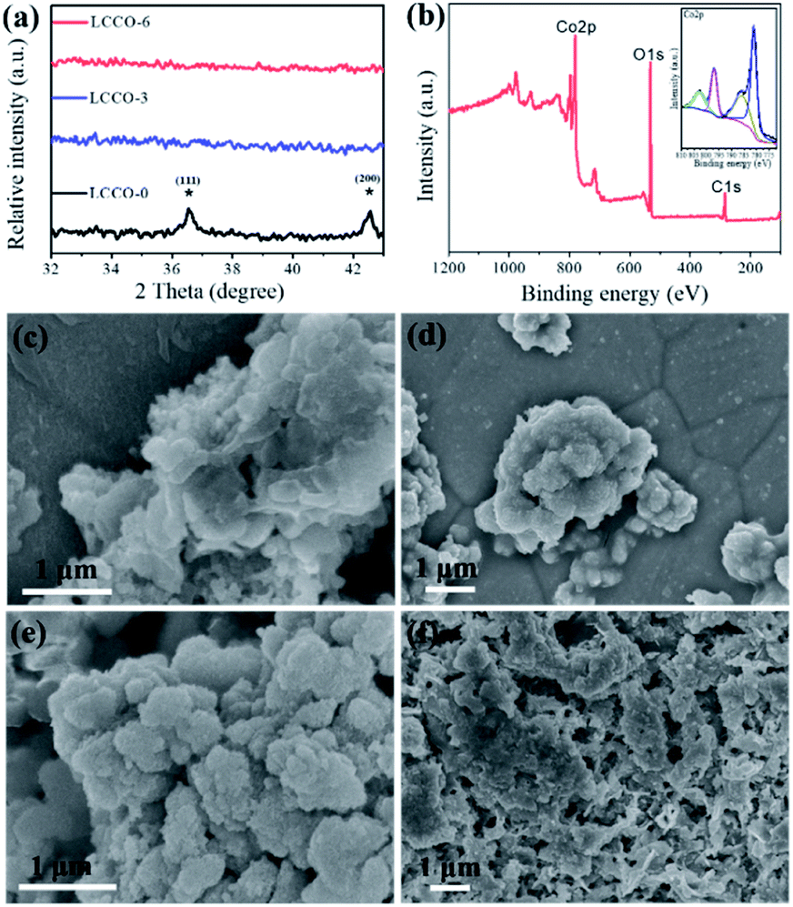 | ||
| Fig. 2 (a) XRD patterns of LCCO-0, 3, and 6. (b) XPS complete survey spectrum of LCCO-6 (inset is the high resolution spectrum for core level XPS spectrum of Co 2p). SEM images of as-prepared low-crystalline cobalt monoxide (c) LCCO-0, (d) LCCO-3, (e) LCCO-6, and (f) LCCO-15. | ||
X-ray photoelectron spectroscopy (XPS) measurements were carried out to investigate the atom chemical states of LCCO-6. Fig. 2b shows the complete spectrum, it demonstrated the existence of Co, O, C elements. The spectrum that fit for Co 2p is presented in the inset of Fig. 2b, consisted of strong spin–orbit doublet peaks at 781.6 and 797.7 eV and shakeup satellite peaks at 785.8 and 802.7 eV, which are generally associated with Co2+.36,41,51 The XPS spectra of the other LCCO-0, LCCO-3 and LCCO-15 are shown in Fig. S3.† Since their spectra have no obvious difference, which confirms the unchanged component after the lithiation–delithiation process.
Scanning electron microscopy (SEM) was employed to investigate morphology changes before and after the lithiation–delithiation process. Fig. 2c–f show the SEM images of LCCO-0, 3, 6, and 15, respectively (the corresponding high-magnification SEM images are shown in Fig. S4†). As shown in Fig. 2c and S4a,† the LCCO-0 presents smooth surface and non-uniform morphology with different particle sizes and shapes. However, minor changes could be detected in Fig. 2d and S4b† for LCCO-3, it presents a rougher surface than pristine material and some tiny sheets could be detected. With the increase of cycle numbers to six, the surface becomes rougher and rougher, some small particles or sheets anchored on the surface. It is worth noting that both LCCO-3 and LCCO-6 preserve their original structural integrity and no severe pulverization, collapse, or agglomeration appeared. As illustrated in Fig. 2f and S4d,† LCCO-15 suffers fearful structural destruction, and pristine morphology are no longer retained, exhibiting severe pulverization and agglomeration.
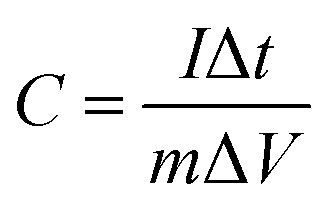
Transition electron microscopy (TEM) and high-resolution transition electron microscopy (HRTEM) was employed to investigate the inner evolution and low-crystalline structure of LCCO-6. Typical TEM images (Fig. 3a) of LCCO-6 present its irregular microparticles and rough surface with many small particles, which is in accordance with SEM images (Fig. 2e). The rough surface may originate from the continuous conversion in the charge–discharge processes; as shown in enlarged view (Fig. 3b), which differs from previous reported low-crystalline structure.35,36 There are many crack-like multiple channels inside the bulk materials, the inset presents an enlarged view of the channels: the channels connect with each other and form crack-like paths. The formed three-dimensional connected channels can facilitate the ion/electron diffusion and transfer, on the other hand, channels can support more metal ions take part in the Faraday reaction. The HRTEM images (Fig. 3c) reveal more detailed structural information, with no obvious crystalline lattice fringe existing, which confirms the low-crystalline structure. The electrochemical performance of LCCO electrodes was investigated in a three-electrode system with Pt foil as counter electrode and Ag/AgCl as a reference in 2 M KOH solution. The galvanostatic charge–discharge (GCD) curve of pure Ni foam is shown in Fig. S5.† The super-low capacity indicates that Ni foam is only a substrate and contributes negligible capacity. Fig. 4a shows the Cyclic Voltammetry (CV) profile of CoO after different lithiation–delithiation cycles at 5 mV s−1, as expected, two pairs of prominent redox peaks can be detected, which correspond to the conversion of Co2+/Co3+ (P1, P4) and Co3+/Co4+ (P2, P3), respectively.33,52 The distinct redox peaks indicate the Faraday mechanism of all the LCCO samples.27 It is distinct that the LCCO-3, 6, and 15 possess a much enlarged integrated area than LCCO-0, revealing the feasibility of improving specific capacitance. LCCO-6 shows a larger integrated area than LCCO-3, which can be ascribed to the lower crystalline degree and more inner 3D-connected channels after lithiation–delithiation process, additionally, LCOO-15 with the severe active material pulverization and aggregation impedes the diffusion and permeation of electrolyte show decreasing integrated area. Fig. 4b shows the CV curves of LCCO-6 at different scan rates in the range from 0 to 0.6 V (vs. Ag/AgCl), with the increase of scanning rate, all the CV curves present enlarged integrated area, the anode peaks shift slightly toward higher potential area while the cathode peaks shift toward lower potential area due to the insufficient intercalation of ions from the electrolyte into the inner of active materials. Meanwhile, the shapes of CV curves remain unchanged indicates the excellent electron conductivity and reversibility.51,53 Chronopotentiometry (CP) techniques were used to estimate the capacitance and cycling stability of low-crystalline. The Galvanostatic Charge–Discharge (GCD) curves at 0.8 A g−1 of LCCO-0, 3, 6, and 15 are illustrated in Fig. 4c, the distinct nonlinearities charge–discharge plateaus show the battery behavior.43 The additional CV and GCD curves of LCCO-0, 3, and 15 at various scan rates and current densities are shown in Fig. S6 in ESI.† According to the GCD curves, the LCCO-6 possesses the longest discharge time, the specific capacitances of LCCO-0, 3, 6, and 15 is calculated from eqn (2):54
 | (2) |
000 cycles, indicating the long-term cycling stability of as-prepared electrodes. Noteworthily, the as-prepared low-crystalline exhibits superior cycling stability to most reported energy storage materials based on metal oxides,5,57 which providing possibility for large-scale applications. The low-crystalline structure kept unchanged even after long cycles, for that there is no distinct lattice fringes in HRTEM (Fig. S7†).
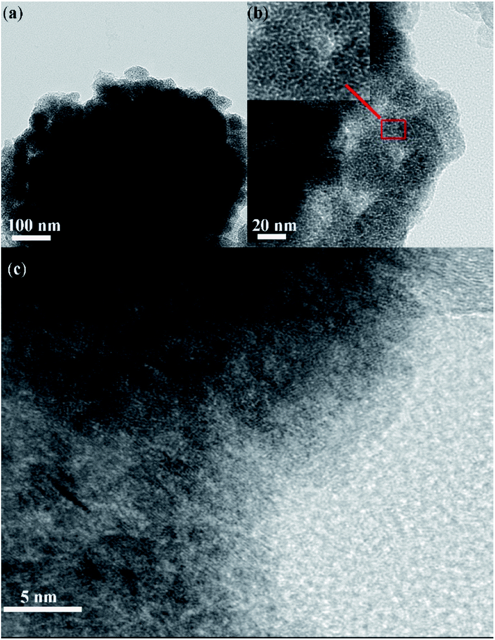 | ||
| Fig. 3 TEM and HRTEM images of LCCO-6. (a) The overall view of low-crystalline microparticle, (b and c) enlarged view of LCCO-6, inset in (b) shows structure at typical area. | ||
 | ||
| Fig. 4 CV curves of (a) LCCO-0, 3, 6, and 15 at 5 mV s−1. (b) LCCO-6 at different scan rates. Galvanostatic charge–discharge (GCD) curves of (c) LCCO-0, 3, 6, and 15 at 1 A g−1. (d) LCCO-6 at different current densities. (e) Rate capacities of LCCO-6. (f) EIS Nyquist plots of LCCO-0, 3, 6, and 15. The inset shows the enlarged portion at the high frequency region. (g) Cycling performance at a constant current density at 10 A g−1 of LCCO-6. | ||
Comparing with the similar lithium-ion insertion–desertion mechanism,13,58 this novel lithiation–delithiation method is deemed to be an effective method to increase the electrochemical performance of the other “conversion-type” metal oxides. Herein, commercial NiO nanoparticles were also treated in a similar way. XRD patterns (Fig. S8†) of commercial.
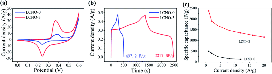
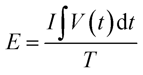
NiO after 0 cycle (LCNO-0) and commercial NiO after 3 cycles (LCNO-3) are shown in the range from 35° to 41°. The LCNO-3 show no diffraction peaks while the diffraction pattern of LCNO-0 presents a distinct peak, suggesting the low-crystalline structure of LCNO-3.35,40,59 The electrochemical performance of assembled lithium batteries was shown in Fig. S9 and S10,† the battery shows higher coulombic efficiency, which can be ascribed to its small particle size. Fig. 5a presents the CV curves of LCNO-3 versus LCNO-0, LCNO-3 possesses a much larger integrated area than LCNO-0, which corresponds to higher specific capacitance. CV curves of both LCNO-0 and LCNO-3 present a pair of distinct redox peaks, indicate their Faraday energy storage mechanism. With the increasing scan rates, the CV curves of LCNO-3 remain unchanged, revealing its good electron conductivity (shown in Fig. S11†). Fig. 5b shows the GCD curves of LCNO-0 and LCNO-3 at the current density of 1 A g−1, the capacitance can be calculated to be 497.2 F g−1 (66.5 mA h g−1) and 2317.6 F g−1 (302.6 mA h g−1). GCD curves at different current densities are shown in Fig. S12† and rate capacity (Fig. 5c) reveals that about 49.8% retention is obtained at 20 A g−1. The improved electrochemical performance of treated CoO and NiO demonstrates electrochemical lithiation–delithiation is an effective and universal way for “conversion-type” materials.
 | ||
| Fig. 5 (a) CV, (b) GCD, (c) rate capacity of as-prepared LCNO-0 and LCNO-3. | ||
To demonstrate the potential for practical application, a hybrid supercapacitor constructed with LCCO as the positive electrode and AC as the negative electrode was assembled. CV, GCD, and rate capacity curves of AC are presented in Fig. S13–S15.† During the assembly of hybrid supercapacitors, the stored charge in the cathode (q+) and anode (q−) was balanced by the following equation:35
| q = m × C × ΔV | (3) |
 | (4) |
Fig. 6a shows the CV profile of LCCO/AC supercapacitor in the potential range from 0 V to 1.5 V at different scan rates. All the CV curves present rectangle-like shapes at different scan rates, indicating that the capacitance originates from both Faraday redox reactions capacitance and double layer capacitance.60 CP techniques were conducted to investigate the capacitance properties and cycling stability, as shown in Fig. 6b, the GCD curves exhibit excellent linearity and good symmetry, which coincides with the CV profile. High specific capacitance of 163.2 F g−1 is obtained at 1 A g−1, which still kept 118.3 F g−1 even at the high current density of 16 A g−1 as shown in Fig. 6c. To further estimate the energy storage ability of the as-prepared device, eqn (5) and (6) are used to represent the corresponding calculated Ragone plots (Fig. 6d).
 | (5) |
 | (6) |
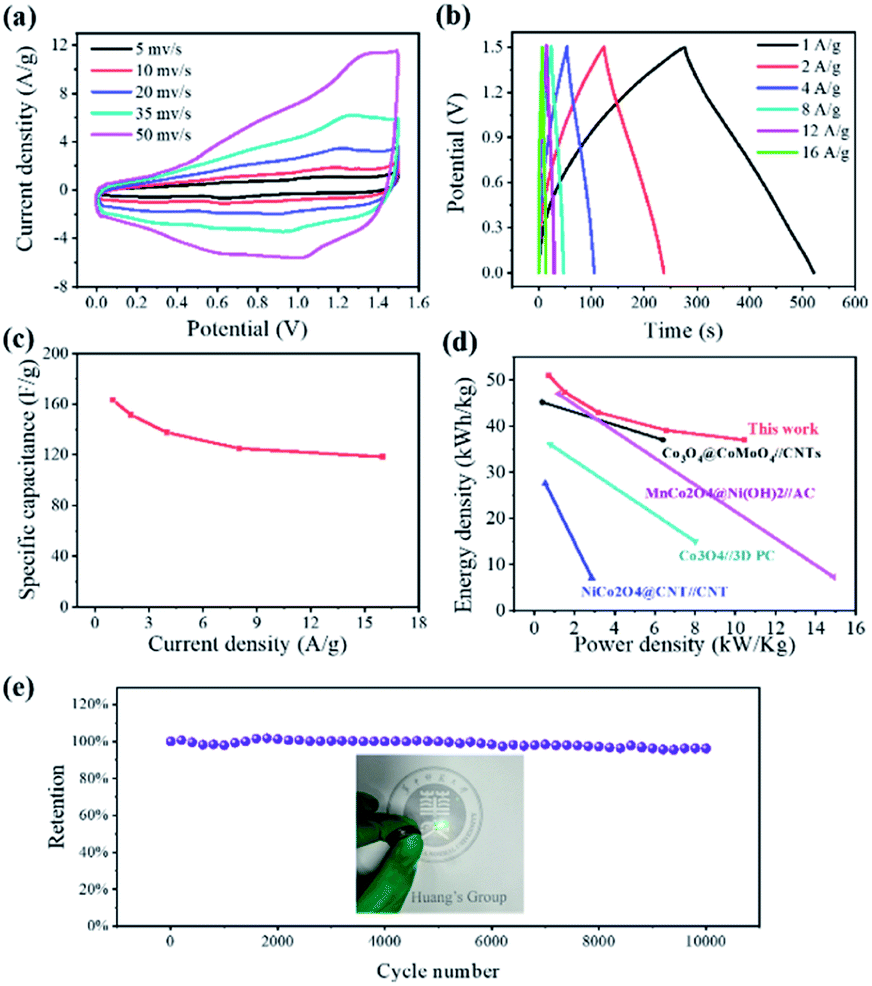 | ||
| Fig. 6 (a) CV (b) galvanostatic charge/discharge curves, (c) rate capacity, (d) Ragone plots, and (e) cycling stability of low-crystalline cobalt monoxide//AC hybrid supercapacitor. Inset shows the optical photograph of lighting an LED (2.5 V). | ||
The energy density was calculated to be 50.9, 47.3, 43.0, 39.1, 37.0 W h kg−1 at the power densities of 0.73, 1.52, 3.18, 6.57, 10.46 kW kg−1. The assembled low-crystalline//AC device achieves a high energy density of 50.9 W h kg−1 (at a power density of 0.73 kW kg−1), which surpasses most reported co-based hybrid supercapacitors such as NiCo2O4@CNT//CNT,52 Co3O4//3D PC,61 Co3O4@CoMoO4//CNTs,44 MnCo2O4@Ni(OH)2//AC.45 As shown in Fig. 6e, the cyclic stability of assembled device was estimated by GCD cycles at the current density of 10 A g−1, the hybrid device exhibits good durability with retention of 96.3% after 10000 cycles, which benefits from the stability of both cathode and anode. To estimate the practical application of devices, two hybrid supercapacitors packaged in a coin cell in series can light one 2.5 V LED (optical photograph in Fig. 6e).
Conclusions
In conclusion, the lithiation–delithiation mechanism was used to synthesis low-crystalline metal oxides with improved electrochemical performance, the lithiation–delithiation-synthesized LCCO and LCNO exhibit remarkable electrochemical performance, which can be ascribed to the following reasons: continuous lithiation–delithiation processes trigger enlarged surface area. Large volume expansion during charge–discharge processes can create empty space inside bulk material and rougher surface, which can provide rich reaction sites. For traditional well-crystalline battery-type capacitive electrode, the strength caused by the reaction of metal ion and OH− may trigger pulverization of active materials and aggregation of particles, thus weaken the cycling stability. While, for low-crystalline structure battery-type capacitive electrode, the loose arrangement of atoms and enough space between crystals can efficiently accommodate the stress during redox processes, further achieving long-term cycling stability. Additionally, differs from previously reported low-crystalline/amorphous metal hydroxides/oxyhydroxides, 3D-connected multiple channels are created by the constant volume expansion/contraction during the lithiation–delithiation process. Those channels can accelerate the ion diffusion and electron transfer. When the electrode was tested in three-electrode system, it exhibits high specificity of 2154.1 F g−1 (299.2 mA h g−1) at 0.8 A g−1, outstanding rate capacitance retention of 63.9% at 22.4 A g−1, and superior cycling stability with 90.5% retention after 10000 cycles. When assembled as hybrid supercapacitors, the devices show maximum energy density of 50.9 W h kg−1. Additionally, the other metal oxides (LCNO) also show high performance with this strategy. Our method is expected to open a door for engineering low-crystalline metal oxides using as hybrid supercapacitors electrodes.
Author contributions
Zhuo-Dong Wu: validation, visualization, writing – review & editing, supervision, software, data curation, formal analysis. De-Jian Chen: conceptualization, writing – original draft. Long Li: project administration, methodology. Li-Na Wang: funding acquisition, resources.Conflicts of interest
There are no conflicts to declare.Acknowledgements
The authors would like to acknowledge the support of project supported by Southern Marine Science and Engineering Guangdong Laboratory (Zhuhai) (SML2020SP007).References
- C. Liu, F. Li, L. P. Ma and H. M. Cheng, Adv. Mater., 2010, 22, E28–E62 CrossRef CAS PubMed.
- J. Cabana, L. Monconduit, D. Larcher and M. R. Palacin, Adv. Mater., 2010, 22, E170–E192 CrossRef CAS PubMed.
- M. Armand and J.-M. Tarascon, Nature, 2008, 451, 652–657 CrossRef CAS PubMed.
- F. Cheng, J. Liang, Z. Tao and J. Chen, Adv. Mater., 2011, 23, 1695–1715 CrossRef CAS PubMed.
- W. Zhou and L. Guo, Chem. Soc. Rev., 2015, 44, 6697–6707 RSC.
- J. Jiang, Y. Li, J. Liu, X. Huang, C. Yuan and X. W. Lou, Adv. Mater., 2012, 24, 5166–5180 CrossRef CAS PubMed.
- L. Jolivet, M. Leprince, S. Moncayo, L. Sorbier, C. P. Lienemann and V. Motto-Ros, Spectrochim. Acta, Part B, 2019, 151, 41–53 CrossRef CAS.
- T. Kim, W. Song, D.-Y. Son, L. K. Ono and Y. Qi, J. Mater. Chem. A, 2019, 7, 2942–2964 RSC.
- H. Wang, S. Xu, C. Tsai, Y. Li, C. Liu, J. Zhao, Y. Liu, H. Yuan, F. Abild-Pedersen, F. B. Prinz, J. K. Nørskov and Y. Cui, Science, 2016, 354, 1031–1036 CrossRef CAS PubMed.
- M. Zheng, H. Tang, L. Li, Q. Hu, L. Zhang, H. Xue and H. Pang, Adv. Sci., 2018, 5, 1700592 CrossRef PubMed.
- F. Song, L. Bai, A. Moysiadou, S. Lee, C. Hu, L. Liardet and X. Hu, J. Am. Chem. Soc., 2018, 140, 7748–7759 CrossRef CAS PubMed.
- P. Poizot, S. Laruelle, S. Grugeon, L. Dupont and J. Tarascon, Nature, 2000, 407, 496–499 CrossRef CAS PubMed.
- K. He, H. L. Xin, K. Zhao, X. Yu, D. Nordlund, T.-C. Weng, J. Li, Y. Jiang, C. A. Cadigan and R. M. Richards, Nano Lett., 2015, 15, 1437–1444 CrossRef CAS PubMed.
- L. Luo, J. Wu, J. Xu and V. P. Dravid, ACS Nano, 2014, 8, 11560–11566 CrossRef CAS PubMed.
- Y. Yuan, K. Amine, J. Lu and R. Shahbazian-Yassar, Nat. Commun., 2017, 8, 15806 CrossRef CAS.
- Q. Su, D. Xie, J. Zhang, G. Du and B. Xu, ACS Nano, 2013, 7, 9115–9121 CrossRef CAS PubMed.
- S. Zhao, D.-W. Wang, R. Amal and L. Dai, Adv. Mater., 2019, 31, 1801526 CrossRef PubMed.
- D. Gu, W. Li, F. Wang, H. Bongard, B. Spliethoff, W. Schmidt, C. Weidenthaler, Y. Xia, D. Zhao and F. Schüth, Angew. Chem., 2015, 127, 7166–7170 CrossRef.
- X. Xu, R. Cao, S. Jeong and J. Cho, Nano Lett., 2012, 12, 4988–4991 CrossRef CAS PubMed.
- X. Wang, D.-M. Tang, H. Li, W. Yi, T. Zhai, Y. Bando and D. Golberg, Chem. Commun., 2012, 48, 4812–4814 RSC.
- Z.-S. Zhu, X.-J. Yu, J. Qu, Y.-Q. Jing, Y. Abdelkrim and Z.-Z. Yu, Appl. Catal., B, 2020, 261, 118238 CrossRef CAS.
- W. Wei, L. Mi, Y. Gao, Z. Zheng, W. Chen and X. Guan, Chem. Mater., 2014, 26, 3418–3426 CrossRef CAS.
- W. Wei, J. Wu, S. Cui, Y. Zhao, W. Chen and L. Mi, Nanoscale, 2019, 11, 6243–6253 RSC.
- W. Wei, W. Ye, J. Wang, C. Huang, J.-B. Xiong, H. Qiao, S. Cui, W. Chen, L. Mi and P. Yan, ACS Appl. Mater. Interfaces, 2019, 11, 32269–32281 CrossRef CAS PubMed.
- R. Li, Y. Wang, C. Zhou, C. Wang, X. Ba, Y. Li, X. Huang and J. Liu, Adv. Funct. Mater., 2015, 25, 5384–5394 CrossRef CAS.
- W. Zuo, R. Li, C. Zhou, Y. Li, J. Xia and J. Liu, Adv. Sci., 2017, 4, 1600539 CrossRef PubMed.
- M. Wang, Z. Li, C. Wang, R. Zhao, C. Li, D. Guo, L. Zhang and L. Yin, Adv. Funct. Mater., 2017, 27, 1701014 CrossRef.
- G. Xiong, P. He, D. Wang, Q. Zhang, T. Chen and T. S. Fisher, Adv. Funct. Mater., 2016, 26, 5460–5470 CrossRef CAS.
- W. He, C. Wang, H. Li, X. Deng, X. Xu and T. Zhai, Adv. Energy Mater., 2017, 7, 1700983 CrossRef.
- Y. Xiao, S. Liu, F. Li, A. Zhang, J. Zhao, S. Fang and D. Jia, Adv. Funct. Mater., 2012, 22, 4052–4059 CrossRef CAS.
- T. Zhai, L. Wan, S. Sun, Q. Chen, J. Sun, Q. Xia and H. Xia, Adv. Mater., 2017, 29, 1604167 CrossRef PubMed.
- G. Meng, Q. Yang, X. Wu, P. Wan, Y. Li, X. Lei, X. Sun and J. Liu, Nano Energy, 2016, 30, 831–839 CrossRef CAS.
- C. Zhou, Y. Zhang, Y. Li and J. Liu, Nano Lett., 2013, 13, 2078–2085 CrossRef CAS PubMed.
- P. Wu, S. Cheng, M. Yao, L. Yang, Y. Zhu, P. Liu, O. Xing, J. Zhou, M. Wang and H. Luo, Adv. Funct. Mater., 2017, 27, 1702160 CrossRef.
- K. A. Owusu, L. Qu, J. Li, Z. Wang, K. Zhao, C. Yang, K. M. Hercule, C. Lin, C. Shi, Q. Wei, L. Zhou and L. Mai, Nat. Commun., 2017, 8, 14264 CrossRef PubMed.
- H. Li, Y. Gao, C. Wang and G. Yang, Adv. Energy Mater., 2015, 5, 1401767 CrossRef.
- W. Jiang, D. Yu, Q. Zhang, K. Goh, L. Wei, Y. Yong, R. Jiang, J. Wei and Y. Chen, Adv. Funct. Mater., 2015, 25, 1063–1073 CrossRef CAS.
- Q. Lu, Z. J. Mellinger, W. Wang, W. Li, Y. Chen, J. G. Chen and J. Q. Xiao, ChemSusChem, 2010, 3, 1367–1370 CrossRef CAS PubMed.
- M. Bernard, R. Cortes, M. Keddam, H. Takenouti, P. Bernard and S. Senyarich, J. Power Sources, 1996, 63, 247–254 CrossRef CAS.
- J. Liu, M. Zheng, X. Shi, H. Zeng and H. Xia, Adv. Funct. Mater., 2016, 26, 919–930 CrossRef CAS.
- H. Li, M. Yu, X. Lu, P. Liu, Y. Liang, J. Xiao, Y. Tong and G. Yang, ACS Appl. Mater. Interfaces, 2014, 6, 745–749 CrossRef CAS PubMed.
- J. Chen, J. Xu, S. Zhou, N. Zhao and C.-P. Wong, Nano Energy, 2016, 25, 193–202 CrossRef CAS.
- Y. Wang, Y. Song and Y. Xia, Chem. Soc. Rev., 2016, 45, 5925–5950 RSC.
- J. Wang, X. Zhang, Q. Wei, H. Lv, Y. Tian, Z. Tong, X. Liu, J. Hao, H. Qu and J. Zhao, Nano Energy, 2016, 19, 222–233 CrossRef CAS.
- Y. Zhao, L. Hu, S. Zhao and L. Wu, Adv. Funct. Mater., 2016, 26, 4085–4093 CrossRef CAS.
- J. Sundaramurthy, V. Aravindan, P. Suresh Kumar, S. Madhavi and S. Ramakrishna, J. Phys. Chem. C, 2014, 118, 16776–16781 CrossRef CAS.
- X. Lu, Y. Zeng, M. Yu, T. Zhai, C. Liang, S. Xie, M. S. Balogun and Y. Tong, Adv. Mater., 2014, 26, 3148–3155 CrossRef CAS PubMed.
- J. Jiang, J. Liu, R. Ding, X. Ji, Y. Hu, X. Li, A. Hu, F. Wu, Z. Zhu and X. Huang, J. Phys. Chem. C, 2010, 114, 929–932 CrossRef CAS.
- F. Han, D. Li, W. C. Li, C. Lei, Q. Sun and A. H. Lu, Adv. Funct. Mater., 2013, 23, 1692–1700 CrossRef CAS.
- N. Chen, J. Zhou, Q. Kang, H. Ji, G. Zhu, Y. Zhang, S. Chen, J. Chen, X. Feng and W. Hou, J. Power Sources, 2017, 344, 185–194 CrossRef CAS.
- U. M. Patil, J. S. Sohn, S. B. Kulkarni, S. C. Lee, H. G. Park, K. V. Gurav, J. Kim and S. C. Jun, ACS Appl. Mater. Interfaces, 2014, 6, 2450–2458 CrossRef CAS PubMed.
- J. Lin, Y. Liu, Y. Wang, H. Jia, S. Chen, J. Qi, C. Qu, J. Cao, W. Fei and J. Feng, J. Power Sources, 2017, 362, 64–72 CrossRef CAS.
- F. Lu, M. Zhou, W. Li, Q. Weng, C. Li, Y. Xue, X. Jiang, X. Zeng, Y. Bando and D. Golberg, Nano Energy, 2016, 26, 313–323 CrossRef CAS.
- P. Yang and W. Mai, Nano Energy, 2014, 8, 274–290 CrossRef CAS.
- M. Qorbani, T.-C. Chou, Y.-H. Lee, S. Samireddi, N. Naseri, A. Ganguly, A. Esfandiar, C.-H. Wang, L.-C. Chen and K.-H. Chen, J. Mater. Chem. A, 2017, 5, 12569–12577 RSC.
- F. Lai, Y. E. Miao, L. Zuo, H. Lu, Y. Huang and T. Liu, Small, 2016, 12, 3235–3244 CrossRef CAS PubMed.
- G. Zhang, X. Xiao, B. Li, P. Gu, H. Xue and H. Pang, J. Mater. Chem. A, 2017, 5, 8155–8186 RSC.
- X.-Y. Shan, G. Zhou, L.-C. Yin, W.-J. Yu, F. Li and H.-M. Cheng, J. Mater. Chem. A, 2014, 2, 17808–17814 RSC.
- J.-X. Feng, S.-H. Ye, X.-F. Lu, Y.-X. Tong and G.-R. Li, ACS Appl. Mater. Interfaces, 2015, 7, 11444–11451 CrossRef CAS PubMed.
- H. Chen, L. Hu, M. Chen, Y. Yan and L. Wu, Adv. Funct. Mater., 2014, 24, 934–942 CrossRef CAS.
- R. R. Salunkhe, J. Tang, Y. Kamachi, T. Nakato, J. H. Kim and Y. Yamauchi, ACS Nano, 2015, 9, 6288–6296 CrossRef CAS PubMed.
Footnote |
| † Electronic supplementary information (ESI) available. See DOI: 10.1039/d1ra05814b |
| This journal is © The Royal Society of Chemistry 2021 |