
 Open Access Article
 This Open Access Article is licensed under a Creative Commons Attribution-Non Commercial 3.0 Unported Licence
Synergism of carbon quantum dots and Au nanoparticles with Bi2MoO6 for activity enhanced photocatalytic oxidative degradation of phenol†
Qiang Zhao‡
a,
Zhuangzhuang Zhang‡a,
Ting Yana,
Li Guoa,
Chunming Yang a,
Ge Gaoa,
Yu Wanga,
Feng Fu*a,
Bin Xu*ab and
Danjun Wang*ab
a,
Ge Gaoa,
Yu Wanga,
Feng Fu*a,
Bin Xu*ab and
Danjun Wang*ab
aCollege of Chemistry & Chemical Engineering, Yan'an University, Yan'an 716000, P.R. China. E-mail: binxumail@163.com; yadxfufeng@126.com; wangdj761118@163.com; Tel: +86-010-64434907 Tel: +86-911-233203 Tel: +86-911-2332037
bState Key Laboratory of Organic-Inorganic Composites, Beijing Key Laboratory of Electrochemical Process and Technology for Materials, Beijing University of Chemical Technology, Beijing 100029, P.R. China
First published on 25th August 2021
Abstract
Localized surface plasmon resonance (LSPR) offers an opportunity to enhance the efficiency of photocatalysis. However, the photocatalysts's plasmonic enhancement is still limited, as most metals/semiconductors depend on LSPR contribution of isolated metal nanoparticles. In the present work, carbon quantum dots (CQDs) and Au nanoparticles (NPs) were simultaneously assembled on the surface of a three-dimensional (3D) spherical Bi2MoO6 (BMO) nanostructure with surface oxygen vacancies (SOVs). The collective excitation of CQDs and Au NPs demonstrated an effective strategy to improve the utilization of up-conversion emission and plasmonic energy. The contribution of CQDs and Au NPs assembled on the surface of BMO (7 wt% CQDs/Au/BMO) realized a photocatalytic phenol degradation enhancement (apparent rate constants, kapp/min−1) of 56.5, 9.5 and 3.9, and 2.2-fold increase compared to BMO, BMO-SOVs, Au/BMO and CQDs/BMO, respectively. The as-fabricated 7 wt% CQDs/Au/BMO exhibited the highest mineralization rate for phenol degradation with 72.4% TOC removal rate in 120 min. The excellent photocatalytic performance of CQDs/Au/BMO was attributed to the synergistic effect of CQDs, Au NPs and SOVs. The CQD up-conversion emission synergetically boosts Au NPs' LSPR significantly promoting the separation and migration of photogenerated electron (e−)/hole (h+) pairs, which could improve the oxygen molecule activation process and thereby their ability to generate reactive oxygen species (ROS). The present work is a step forward to understand and construct similar photocatalysts using an entirely reasonable hypothesis of activity enhancement mechanism according to the active species capture experiments and band structure analysis.
1 Introduction
The presence of phenolic compounds in industrial wastewater has dramatically increased in the past few decades leading to serious aqueous environmental pollution and human health hazards.1–3 Many methods have been adopted to remove these phenolic compounds from the aquatic environment, such as adsorption,3,4 biodegradation,5 and photocatalysis.6–9 In comparison to traditional technology, semiconductor photocatalysis has the merits of cheapness, non-toxicity, high-stability, strong oxidation ability and eco-friendliness with the future promise of practical purification technology.10–15The efficient photocatalysis requires effective generation and separation of photogenerated charges and their rapid migration to specific sites for further reaction. Nevertheless, single-component semiconductor-based photocatalytic efficiency is limited by their poor electron–hole separation and migration.11,13,16–18 To date, tremendous efforts have devoted to addressing these issues.12,13 Various strategies have been developed to improve the efficiency of separating and transferring photogenerated charge carriers, including doping, surface modification, defect engineering, and constructing heterostructures.19–24 So far, many photocatalysts have been successfully constructed based on various strategies, and several photocatalytic mechanisms, i.e., Z-scheme or heterojunctions.10–24 The bismuth-based composite oxide, Bi2MoO6 has shown excellent photoelectric properties with partially responsive to visible light spectrum.25–27 However, the photocatalytic efficiency is limited due to its infective utilization of visible light and high recombination of photogenerated electron/hole (e−/h+). Several reports are available for Bi2MoO6-based photocatalytic materials with different morphologies and size produced via different synthesis and modification strategies. The practical application of Bi2MoO6-based material is still insufficient based on its high e−/h+ recombination rate, slow carriers migration and narrow visible light response range.15–29 The modification on Bi2MoO6 in the literature is primarily focused on improving its photocatalytic performance using a single strategy, which is insufficient to overcome the shortcomings of Bi2MoO6.27–29 Accordingly, using multiple approaches to coordinate and control Bi2MoO6-based catalytic materials performance could be a meaningful strategy to improve the separation efficiency of photogenerated e−/h+ and widen the absorption range to promote the catalytic performance of Bi2MoO6-based catalysts.
Carbon quantum dots (CQDs) has attracted extensive attention, due to its non-toxicity, good biocompatibility, easy synthesis and chemical inertness, strong up-conversion ability and good electron transfer performance.30–33 Therefore, CQDs are widely used for modifying semiconductors to promote their photocatalytic activity, such as CQDs/Cu2O,34 CQDs/CdS,35 CQDs/Bi2MoO6,36 CQDs/BiPO4,37 CQDs/g-C3N4,38 CQDs/TiO2,39 and CQDs/Bi2WO6,40 etc. The noble metal nanoparticles (Au, Ag, Pt, etc.) have strong local surface plasmon resonance (LSPR), and thus anchoring these metal nanoparticles onto the surface of the semiconductor could broaden the light response region.20,21,41,42 Besides, noble metal nanoparticles with low Fermi level (Ef) have strong electron trapping ability, allowing easy suppressing of photogenerated carrier recombination.42 On the other hand, the regulation of surface oxygen vacancy on a semiconductor can be used to limit photogenerated electron/hole recombination and improve the catalytic efficiency of the photocatalysts.43–45
In the present work, the CQDs and Au nanoparticles (NPs) are simultaneously assembled on the surface of hierarchical Bi2MoO6 with SOVs using a step-by-step assembly strategy. The proposed strategies enable the hierarchical Bi2MoO6 to act as a substrate for assembling CQDs and Au nanoparticles, thereby facilitating close contact and minimum aggregation. The anchoring of Au NPs or CQDs could significantly enhance the visible-light absorption between 500 to 600 nm based on the synergism of the CQDs up-conversion boosted LSPR effect. Furthermore, the CQDs and Au NPs act as the electron-transfer mediator to synergistically promote carriers generation and separation, thereby improve the oxygen activation process and generation of reactive oxygen species (ROS) which could efficiently decompose phenol molecules.
2 Experimental
2.1 Sample preparation
![[thin space (1/6-em)]](https://www.rsc.org/images/entities/char_2009.gif) 000 rapp·min−1 for 30 min to remove large particles. Subsequently, the remaining solution was transferred to vacuum and dried at 80 °C for 3 h to obtain a brownish-black carbon quantum dots, which were donated as CQDs.
000 rapp·min−1 for 30 min to remove large particles. Subsequently, the remaining solution was transferred to vacuum and dried at 80 °C for 3 h to obtain a brownish-black carbon quantum dots, which were donated as CQDs.2.3 Characterization of the as-prepared samples
X-ray powder diffractometer (Shimadzu XRD-7000) was used to analyse the crystallographic properties of the catalyst. X-ray photoelectron spectroscopy (XPS) was obtained using PHI-5400 (America PE) 250 xi system. The morphology of the sample was analysed by scanning electron microscope (SEM, JSM-6700F) and transmission electron microscope (JEM-2100) (Japan electronics). Energy disperse X-ray (EDX) was performed using a field emission scanning electron microscope (JSM-7610F) to analyse the samples elemental features. The photoluminescence (PL) spectra were measured with an FLS 980 Series of Fluorescence Spectrometers (UK). The UV-Vis diffuse reflectance spectra (UV-Vis-DRS) was measured on UV-2550 UV-Vis Spectrophotometer. The electron spin resonance (ESR) spectra were examined on a Bruker model ESR JES-FA200 spectrometer.2.4 Photocatalytic activity measurement
A 400 W halogen lamp equipped with a 420 nm filter was used as the experimental visible-light source. The colourless phenol was used as a simulated pollutant to evaluate the photocatalytic activity of the photocatalyst. In the typical experiment, 200 mg of catalyst and 200 mL of phenol solution with a concentration of 10 mg L−1 were added to the photocatalytic reactor. After magnetic stirring for 30 min under dark conditions to reach adsorption–desorption equilibrium, the sample was irradiated with light. The supernatant was sampled at regular intervals to measure the supernatant's absorbance using 4-aminoantipyrine assisted colourimetric method. The total organic carbon (TOC) were measured via a TOC analyser (Quiti NC 2000s TOC, Jena, Germany).3 Results and discussion
3.1 The formation of CQDs/Au/Bi2MoO6 with surface oxygen vacancies
The rational design and construction of CQDs/Au/Bi2MoO6 (CQDs/Au/BMO) by assembling carbon quantum dots (CQDs) and plasma Au nanoparticles (NPs) onto the hierarchical Bi2MoO6 with SOVs could synergistically promote the photocatalytic degradation of phenol. The overall synthetic route of CQDs/Au/BMO is schematically illustrated in Scheme 1. The CQDs were synthesised through a modified hydrothermal method.37 The pristine hierarchical Bi2MoO6 microspheres with SOVs and Au/Bi2MoO6 were prepared according to our previous report.44,46 The Au/Bi2MoO6 and CQDs were dispersed in ethanol and mixed uniformly using ultrasonic treatment followed by drying and calcination at 250 °C for 2 h to produce CQDs/Au/Bi2MoO6 with surface oxygen vacancies (CQDs/Au/BMO).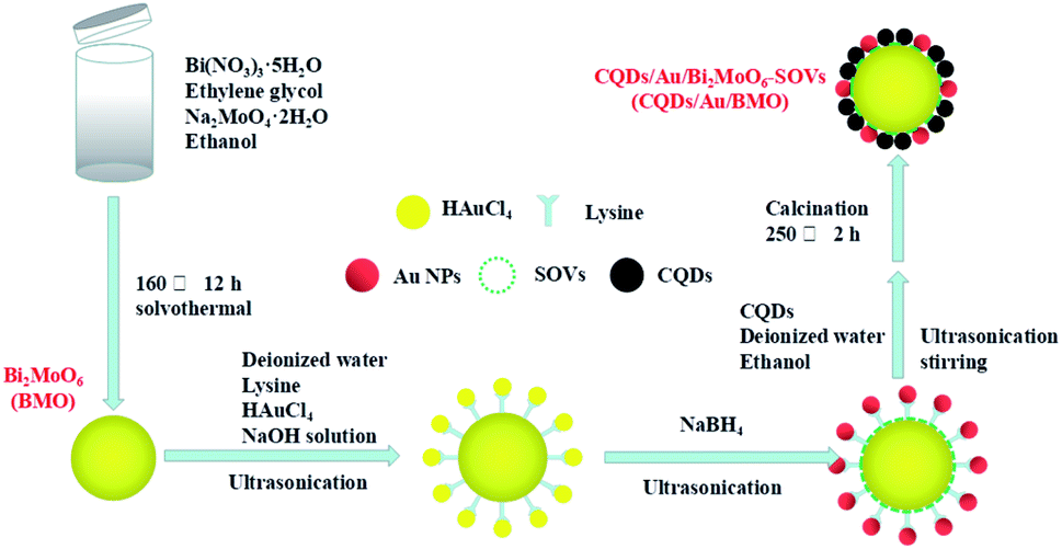 | ||
| Scheme 1 Schematic diagram illustrating the preparation process of the CQDs/Au/BMO composite. | ||
Powder X-ray diffraction (PXRD), energy-dispersive X-ray (EDX) and X-ray photoelectron spectroscopy (XPS) were employed to confirm the formation of CQDs/Au/BMO composites. Fig. 1 reveals the composite formation with orthorhombic BMO (JCPDS No. 76-2388),44 confirming Au NPs and CQDs assembly have no obvious influence on the crystal structure of BMO. The XRD pattern confirms the presence of two weaker diffraction peaks in Au/BMO and CQDs/Au/BMO located at 38.2° and 44.3° attributed to the (111) and (200) planes of Au NPs (JCPDSNo. 80-0019).47 The characteristic diffraction peak of Au NPs could be observed in the series of CQDs/Au/BMO, and the characteristic diffraction peak of carbon could be seen with the increase in CQDs mass loading (Fig. S1†). These two peaks confirm the formation of CQDs/Au/BMO heterostructure. TheXPS profiling is shown in Fig. 2. The CQDs/Au/BMO contains Bi, Mo, O, Au and C elements (Fig. 2a), and BMO contains Bi, Mo, O and C as main elements. Fig. 2b shows the characteristic peak of standard C 1s in the sample of BMO situated 284.8 eV, whereas the CQDs/Au/BMO can be divided into three peaks, 284.77, 286.2 and 288.37 eV, respectively. The three peaks are attributed to sp2 hybrid carbon (C![[double bond, length as m-dash]](https://www.rsc.org/images/entities/char_e001.gif) C), C–O and CO of CQDs, respectively.36
C), C–O and CO of CQDs, respectively.36
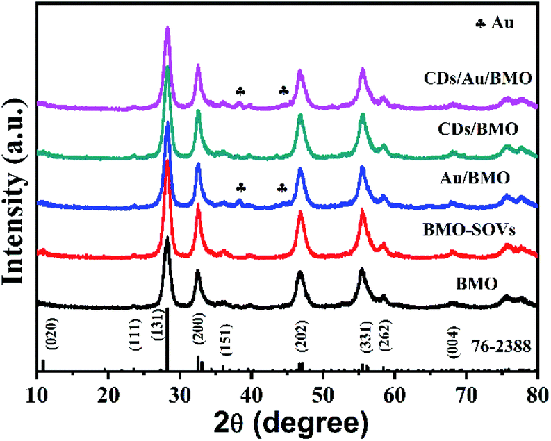 | ||
| Fig. 1 The XRD patterns recorded for pure BMO, BMO-SOVs, Au/BMO, CQDs/BMO and CQDs/Au/BMO composites. | ||
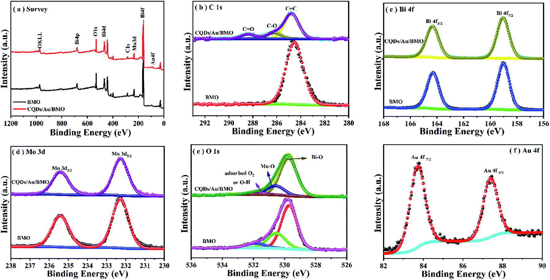 | ||
| Fig. 2 XPS spectrum of BMO and CQDS/Au/BMO (a) survey spectrum; (b) C 1s; (c) Bi 4f; (d) Mo 3d; (e) O 1s and (f) Au 4f. | ||
Fig. 2c reveals two characteristic peaks of BMO with binding energies of 159 and 164.4 eV corresponding to Bi 4f7/2 and Bi4f5/2 of Bi3+.44,45,48 The binding energies of Mo 3d5/2 and Mo 3d3/2 in BMO (Fig. 2d) corresponded to the Mo6+ state at 232.5 and 235.6 eV.44,45 The O element of BMO could be deconvoluted to three asymmetric O1s peaks at 529.8, 530.6 and 531.9 eV (Fig. 2e) related to Bi–O, Mo–O and H–O bonds and adsorbed oxygen, respectively. The binding energies of Bi, Mo and O of CQDs/Au/BMO heterostructure in comparison to BMO have slightly positive shifted binding energies confirming the interaction among BMO, Au and CQDs. The binding energies of peaks located at 84.6 and 88.2 eV correspond to Au 4f7/2 and Au 4f5/2,47 indicating that Au exists in a free state in CQDs/Au/BMO heterostructures (Fig. 2f).
As shown in Fig. 3a and b, BMO possesses a hierarchical microsphere with an average diameter of about 1–2 μm, composed of many assembled nanosheets. The morphology of BMO-SOVs (Fig. S2a and b†), Au/BMO (Fig. S2c and d†), CQDs/BMO (Fig. S2e and f†) and CQDs/Au/BMO (Fig. 3c and d) are similar to that of BMO. In addition, EDX-mapping indicates that all the elements are uniformly distributed (Fig. 3e). To further testify the formation of CQDs/Au/BMO, TEM/HR-TEM and EPR analysis was carried out, as shown in Fig. 4 and Fig. 5. The TEM images show that the BMO has a spherical structure composed of many nanosheets (Fig. 4a). The lattice spacing of 0.315 nm corresponds to the (131) crystal plane of BMO (Fig. 4b). Fig. 4c and d shows the TEM and HR-TEM images of CQDs/Au/BMO, respectively. After deconvolution, the crystal lattice stripes of 0.315 nm, 0.238 nm and 0.32 nm could be ascribed to (131) crystal plane of BMO,44 (111) crystal plane of Au (red-dotted circle) and (002) crystal plane of CQDs (blue-dotted circle), respectively.49,50 The observation is consistent with the XRD results confirming the composite formation between BMO, Au and CQDs.
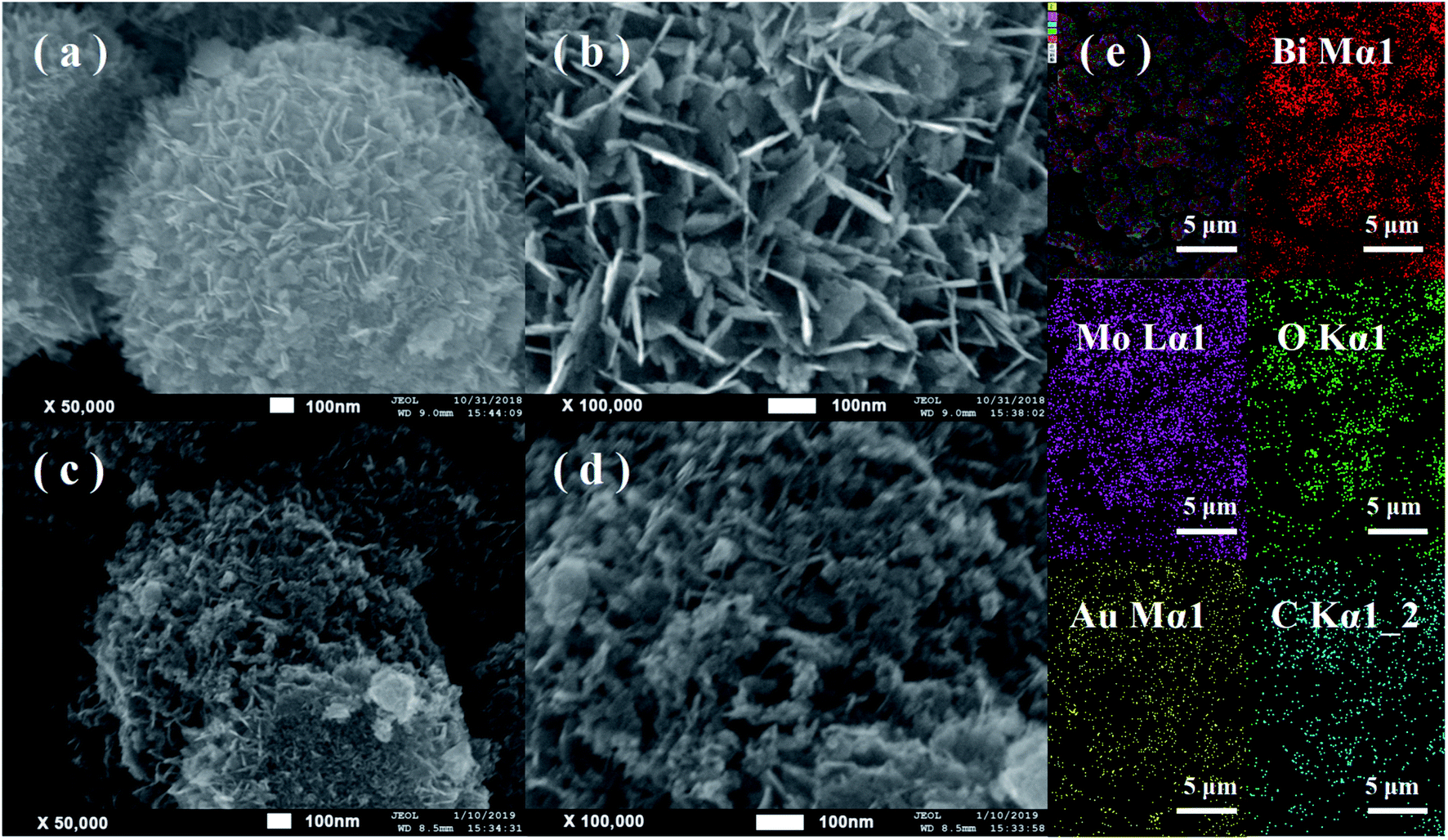 | ||
| Fig. 3 FE-SEM images of (a and b) hollow BMO microsphere and (c and d) CQDs/Au/BMO; (e) EDX spectrum of sample CQDs/Au/BMO showing the presence of Bi, Mo, O, Au and C elements. | ||
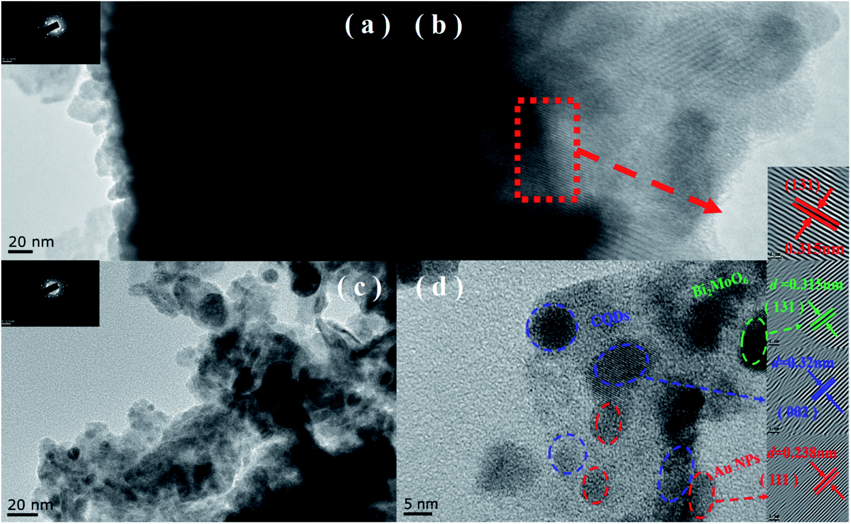 | ||
| Fig. 4 TEM and HR-TEM image of BMO microsphere (a and b) and (c and d) CQDs/Au/BMO. | ||
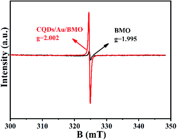 | ||
| Fig. 5 EPR spectra of oxygen vacancies in BMO and CQDs/Au/BMO. | ||
The existence of oxygen defects leaves unpaired electrons in the lattice. Thus, the surface oxygen vacancies (SOVs) state of BMO and CQD/Au/BMO were investigated by the EPR spectroscopy, as shown in Fig. 5. The EPR spectrum of BMO shows a weak signal at g = 2.002, ascribed to the oxygen vacancy generated during the solvothermal process.46 During the reduction of HAuCl4, excessive NaBH4 acts as an oxygen scavenger for producing the active hydrogen. The strong reduction capability of active hydrogen could remove the oxygen atoms from the surface of BMO, thus forming SOVs.51 For CQDs/Au/BMO composite, a strong peak with Lorentzian line-shape emerges at g = 2.002, originating from unpaired electrons. The EPR signal in case of the composite is superior to BMO, which indicates that NaBH4 reduction and calcination could further increase the concentration of SOVs.46,51 The EPR results confirm the formation of SOVs in the CQDs/Au/BMO composite.
3.2 Photocatalytic performance
Fig. 6a and Fig. S3a† show the phenol degradation activities using the prepared photocatalysts. The degradation efficiency of BMO is about 7% when exposed to visible light for 120 min, whereas the Au/BMO, CQDs/BMO and CQDs/Au/BMO demonstrate improved efficiencies with 7% CQDs/Au/BMO exhibiting the best photocatalytic efficiency, with the 94% phenol degradation rate. Fig. 6b shows that the photocatalytic degradation of phenol follows a pseudo-first-order kinetic model.45 The ln(C0/C) = kapp·t, where C0, C represent the concentration of phenol in solution at initial and after t minutes of irradiation and kapp/min−1 is the apparent rate constant (Fig. 6b). The apparent rate constants (kapp/min−1) of BMO, BMO-SOVs, Au/BMO, CQDs/BMO and CQDs/Au/BMO were 4.0 × 10⁻⁴, 24.1 × 10⁻⁴, 59.2 × 10⁻⁴, 106 × 10−4 and 228.21 × 10⁻⁴ min−1, respectively. The kapp of 7% CQDs/Au/BMO for phenol degradation was about 57 and 9.5 fold higher than BMO BMO-SOVs, respectively (Fig. 6c). As illustrated in Fig. 6d, the absorption peak of CQDs/Au/BMO at 507 nm decreases quickly under visible-light irradiation. At the same time, a gradual decline is observed for BMO and BMO-SOVs. The phenol degradation efficiency was optimised against the CQDs content, where improved efficiency was observed with a gradual increase of CQDs. Among all, the 7% CQDs/Au/BMO showed the best photocatalytic activity (Fig. S3c†) with superior mineralisation rate for phenol degradation compared to BMO, realizing 72.4% TOC removal rate within 120 min. Also, the TOC removal rate of phenol on 7 wt% CQDs/Au/BMO is much better than that of BMO-SOVs (24%), Au/BMO (45%), CQDs/BMO (51%), respectively (Fig. 7). The measured performance was found analytically superior compared to some previously reported Bi2MoO6-based catalysts (Table S1†).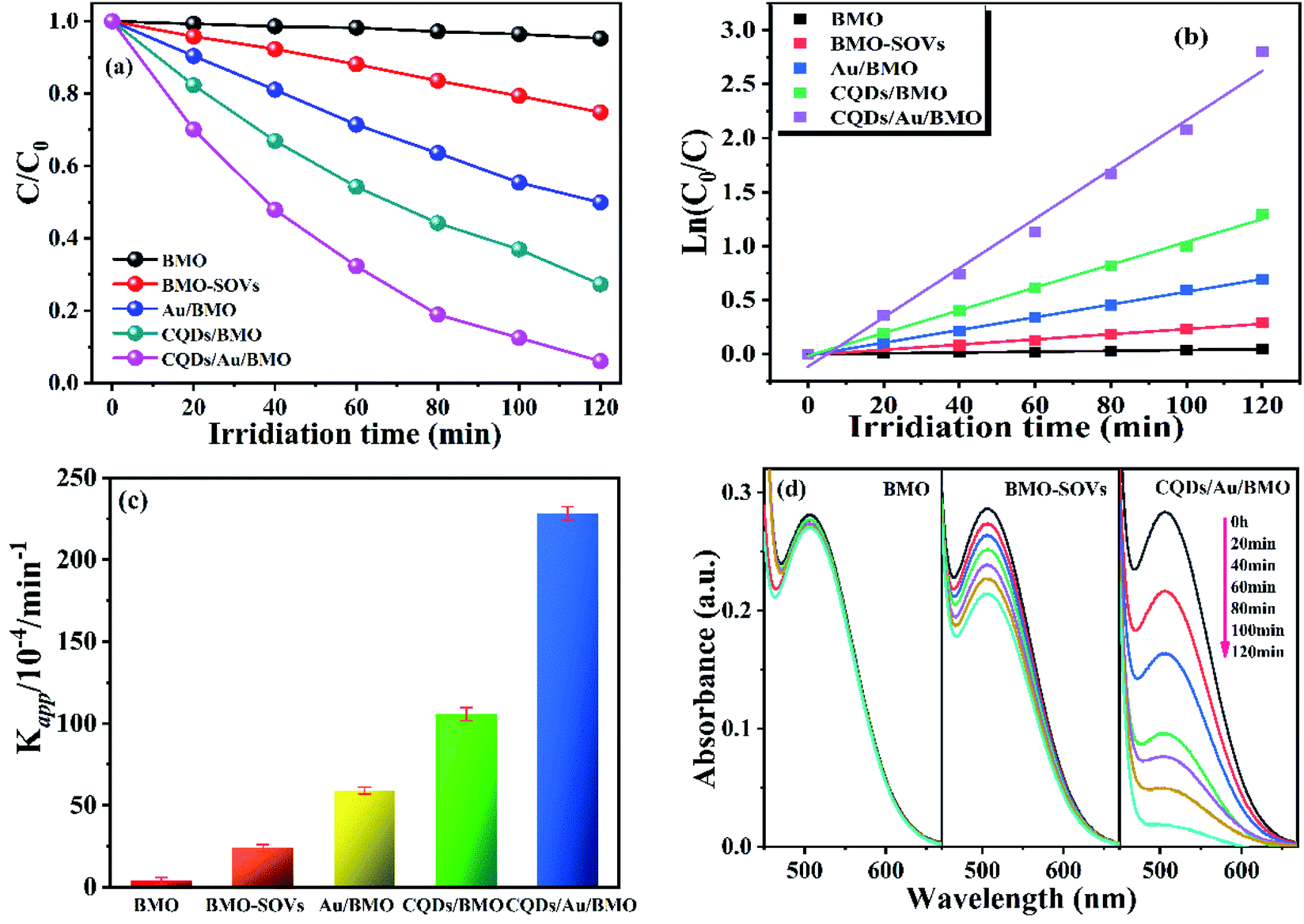 | ||
| Fig. 6 (a) The photocatalytic degradation efficiency of phenol using different photocatalysts, (b) corresponding kinetic plot of ln(C0/C) versus with irradiation time, (c) the photodegradation rate constants, and (d) the absorption spectra's of phenol under visible-light irradiation by using BMO, BMO-SOVs, and CQDs/Au/BMO as catalysts, respectively. | ||
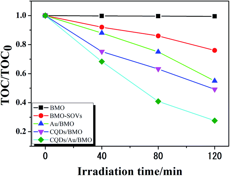 | ||
| Fig. 7 The TOC removal rate of phenol over BMO, BMO-SOVs, Au/BMOm CQDs/BMO and 7 wt% CQDs/Au/BMO composites under visible light illumination. | ||
3.3 Photocatalytic mechanism
The photoluminescence spectroscopy (PL), photocurrent and electrochemical impedance spectroscopy (EIS) were employed to study the separation and transfer efficiency of photogenerated e−/h+ pairs. The photoluminescence intensity could reflect the number of electrons recombined with holes.52,53 As seen, the assembly of Au NPs and CQDs assembling significantly attenuate the PL intensities. Thus, combining Au NPs and CQDs with BMO could significantly promote the separation of electron/hole (e−/h+) pairs as further confirmed via transient photocurrent and EIS measurements. The transient photocurrent response of different photocatalysts under visible light indicates that 7 wt% CQDs/Au/BMO has the strongest photocurrent response (Fig. 8a), proving that the interaction of CQDs and Au NPs on the surface of BMO significantly promotes the separation and transmission of photogenerated carriers.54 Fig. 8b shows the impedance spectra and corresponding equivalent circuit model (inset figure) for pure BMO, BMO-SOVs, Au/BMO, CQDs/BMO and CQDs/Au/BMO. The ohmic resistance (R1), charge transfer resistance (R2 and R3), the Warburg impedance (W) and capacitance for the double layer between photocatalyst and electrolyte (CPE) have also been tabulated as Table S2.† The BMO, BMO-SOVs, Au/BMO, CQDs/BMO and CQDs/Au/BMO electrodes exhibit the similar ohmic resistance (R1), whereas the Au/BMO, CQDs/BMO and CQDs/Au/BMO exhibit lower charge transfer resistance (R2, R3) than that of BMO. The charge transfer resistance (17606 Ω) of CQDs/Au/BMO is much lower than that of pure BMO (35995 Ω), which implies composites efficient carriers transfer ability at the photocatalyst/solution interface.55 The EIS result indicates that CQDs/Au/BMO has the strongest ability to separate and transfer photogenerated e−/h+, and thus facilitating the activity of photocatalyst.
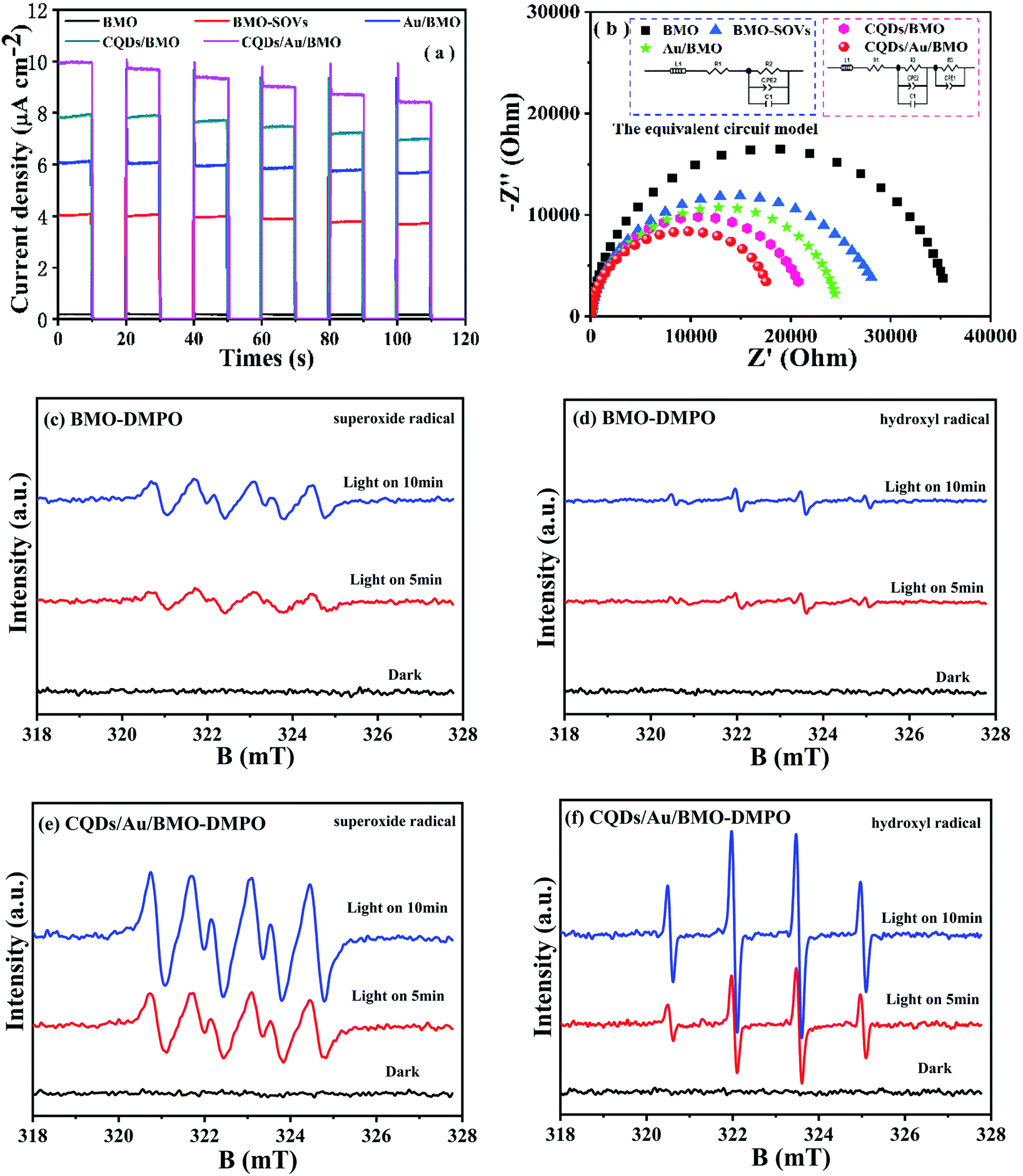 | ||
| Fig. 8 (a) Transient photocurrent response under visible-light irradiation, and (b) the electrochemical impedance spectroscopy (EIS) measurements of BMO, BMO-SOVs, Au/BMO, CQDs/BMO and 7 wt% CQDs/Au/BMO composites; DMPO spin-trapping ESR spectra of (c and d) BMO and (e and f) CQDs/Au/BMO. | ||
It is widely accepted that organic contaminant could be directly or indirectly oxidised via reactive oxygen species (ROS), such as hydroxyl radical (˙OH) and superoxide radical (˙O2−). To further reveal the possible mechanism of oxygen molecule (O2) activation and the formation of ˙O2− and ˙OH, an in situ ESR spin trapping technique was used to identify the main ROS under visible light irradiation (Fig. 8). As seen, the CQDs/Au/BMO exhibit a strong ESR signal for ˙OH and ˙O2− compared to pure BMO, justifying Au NPs and CQDs co-modification in photogenerated charge carrier separation. Thus, promoting the ROS concentration and thereby photocatalytic activity of BMO. Meanwhile, the ROS capture experiments were also carried out by employing ethylenediaminetetraacetic acid disodium salt (EDTA-2Na), isopropyl alcohol (IPA) and benzoquinone (BQ) as scavengers for h+, ˙OH and ˙O2-, respectively.56 The results indicate that EDTA-2Na and BQ could inhibit the photocatalytic degradation of phenol. However, IPA's effect on photocatalytic activity was negligible (Fig. S5†), inferring that the h+ and ˙O2− were the main active species in the photodegradation of phenol as supported by ESR measurement.
To further reveal the process of carrier separation, transfer and the formation mechanism of ROS, the energy band structure and carriers separation efficiency of BMO and CQDs/Au/BMO were investigated. The fluorescence spectrum reveals the superior up-converted photoluminescence properties of the CQDs (Fig. 9). CQDs up-converted emissions range from 400 to 650 nm and could be excited by long-wavelength light from 500 nm to 900 nm. Fig. 10 illustrates that the absorption band edge of BMO is about 470 nm, which broadens post composite formation wit Au and CQDs.
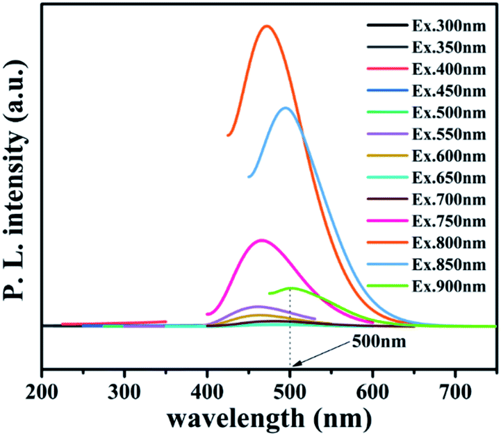 | ||
| Fig. 9 Up-converted photoluminescence spectra of CQDs. | ||
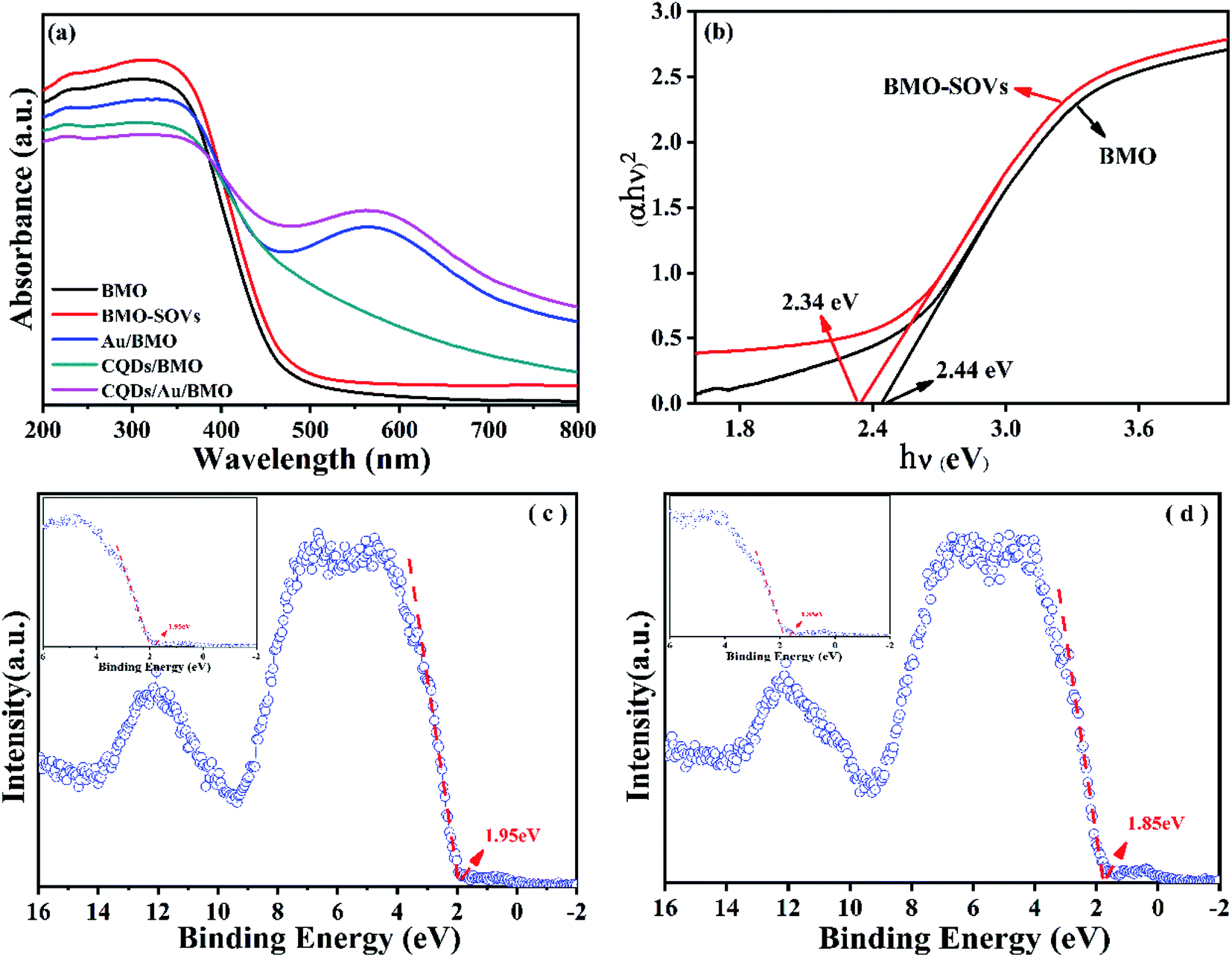 | ||
| Fig. 10 (a) UV-Vis diffuse reflectance spectra of as-prepared samples and (b) band gaps and valence band XPS spectra of (c) BMO and (d) BMO-SOVs. | ||
The Au/BMO exhibits an obvious absorption characteristic peak near 550 nm, ascribed to the strong local surface plasmon resonance (LSPR) of Au nanoparticles.57 Furthermore, CQDs significantly enhance LSPR absorption of Au NPs, due to its up-converted photoluminescence properties (Fig. 9, 10a and S6†). According to Kubelka–Munk function,48 the bandgap values (Eg) of BMO and BMO-SOVs were estimated to be 2.44 and 2.34 eV, respectively (Fig. 10b). The valence band positions (Ev) of BMO and BMO-SOVs can be obtained by the VB-XPS spectra, which were 1.95 and 1.85 eV respectively, as shown in Fig. 10c and d. The Mott–Schottky curves of BMO and BMO-SOVs further indicate positive slopes, confirming these semiconductors n-type behaviour (Fig. S7†). Moreover, the horizontal charged potential of BMO and BMO-SOVs, obtained from the intercept of the slope were −0.36 and −0.35 eV, respectively. It is generally believed that the level charge potential in a semiconductor is equal to the Fermi level (Ef). Thus the interpreted charge potential could represent the Ef of BMO and BMO-SOVs. As the formation of surface oxygen defects (SOVs) has a negligible effect on the Ef level of BMO, the conduction band positions (Ec) of both BMO and BMO-SOVs could be deduced as −0.49 eV (Fig. S8†).
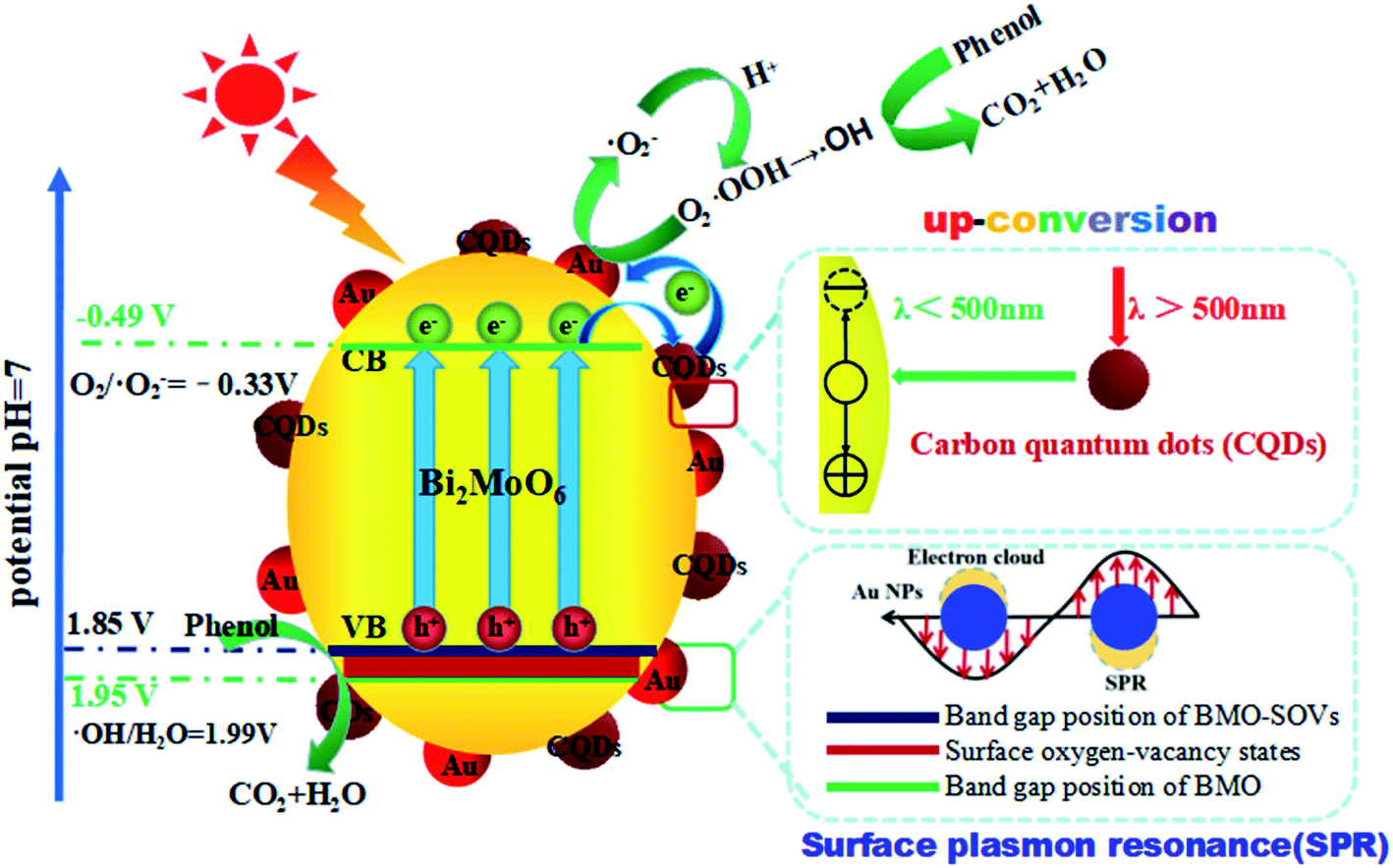
Based on the results mentioned above, a schematic diagram of charge separation and phenol degradation using BMO and CQDs/Au/BMO has been proposed in Scheme 2. It is widely accepted that the SOVs are shallow defects, which may be near the minimum conduction band (CBM) or above the maximum valence band (VBM).58,59 As an n-type semiconductor, SOVs are considered above the VBM of BMO.60 Here, the visible-light illumination allows valence band electrons to get excited to the conduction band (CB), leaving behind the holes on valence band (VB). Since the CBM (−0.53 V vs. NHE) of BMO-SOVs has a lower redox potential compared to O2/˙O2− (−0.33 V vs. NHE), the photogenerated electrons are expected to be captured by the absorbed oxygen (O2) to form superoxide radicals (˙O2−), and then hydroxyl radical (˙OH), which are responsible for the degradation of phenol. Simultaneously, the photogenerated holes left on VB of BMO-SOVs could also participate in photodegradation of phenol. Therefore, for CQDs/Au/BMO catalyst, the synergism of surface plasmon Au, CQDs and SOVs accelerate the catalytic performance allowing rapid phenol degradation under visible light irradiation. Thus, the enhanced photocatalytic activity of CQDs/Au/BMO can be described as follow: the presence of Au NPs, CQDs, and SOVs promotes the light-responsive ability of BMO. Hence, CQDs/Au/BMO could easily excite, generating more photogenerated e−/h+ pairs than pristine BMO. Secondly, the work function energy of Au (5.1 eV) is higher than that of CQDs (4.7 eV), the photogenerated electrons on the CB of BMO tend to transfer to CQDs and Au NPs for storage. These photogenerated electrons on CB of BMO could be transferred directly to Au NPs for storage owing to low Ef level of BMO-SOVs (−0.35 eV vs. NHE61) than Au (0.45 eV vs. NHE).62 Thirdly, the Schottky barriers are formed at the metal–semiconductor nano-junction (Au/BMO) subsequent to the Fermi equilibrium between BMO and Au.63 This unique Au/BMO interface only allows one-sided electron migration from BMO to Au NPs, thus preventing the recombination of e−/h+ pairs.
 | ||
| Scheme 2 Schematic illustration of hole/electron separation and transfer process for the CQDs/Au/BMO photocatalytic under visible-light irradiation. | ||
Moreover, the CQDs could harvest long-wavelength light (λ > 500) and convert it to shorter wavelength light (λ < 500) through the up-conversion process, which in turn boosts the LSPR of Au NPs and excites BMO to form more e−/h+ pairs. Li et al. reported that CQDs/TiO2 composite exhibited the high-efficiency photocatalytic activity for MB degradation due to its attractive up-conversion properties.64 Most importantly, CQDs and Au NPs collective excitation could enhance the utilisation of up-conversion and plasmonic energy (Fig. 10a). Recently, Liu et al. reported utilising the photochemical properties of Au/CQD composite for selective photocatalytic oxidation of cyclohexane to cyclohexanone.65 Thus, the collective excitation of CQDs and Au NPs can eagerly facilitate the generation and migration of the photogenerated electrons from BMO. Here, the CQDs play a key role to support the electron transport channels and enhanced charge separation efficiency. The photogenerated electrons can thus be shuttled freely along the conducting paths of the CQDs, promoting e−/h+ pairs separation at the same time limiting their recombination by accumulating holes on the BMO surface (Scheme 2). The as-fabricated CQDs/Au/BMO composite exhibited a superior catalytic activity, compared to previously reported catalysts for the degradation of phenolic compounds, such as CQDs/Bi2MoO6,36 Au/Bi2MoO6@TiO2 NTAs,43 Au/Bi2MoO6,46 Ag/Bi2MoO6-SOVs,56 Pd-rGO-Bi2MoO6,66 F–Bi2MoO6,67 and Bi2MoO6−x@Bi2MoO6,68 Bi2MoO6/CNTs/g-C3N4,69 CdS/Bi/Bi2MoO6,70 and so on (Table S2†). The analytical superiority of CQDs/Au/BMO confirms the composites practical work ability for removing phenol from wastewater under visible light irradiation. Furthermore, the five-cycled photocatalytic degradation experiments of 7 wt% CQDs/Bi2MoO6 were carried out and the XRD patterns before and after usage were investigated (Fig. S9†). No significant decrease on photocatalytic performance are observed after five recycles, revealing a very high stability of the 7 wt% CQDs/Bi2MoO6, which enable it as a promising candidate to further utilize in industrial applications for the photodegradation of organic pollutants.
4 Conclusions
In this paper, CQDs, Au NPs and SOVs modified BMO photocatalysts were successfully prepared using a simple chemical reduction deposition and calcination process. Improved photogenerated carriers separation efficiency was obtained with widen visible light response range and oxygen molecules activation efficiency (O2). The as-prepared CQDs/Au/BMO photocatalysts demonstrated excellent photocatalytic phenol degradation performance where the 7% CQDs/Au/BMO composite material exhibited 56.5 fold higher photocatalytic efficiency compared to the pristine BMO under visible light irradiation. The excellent photocatalytic performance of CQDs/Au/BMO was mainly attributed to the collective excitation of CQDs and Au NPs, which not only promoted the separation and migration of e−/h+ pairs but also inhibited their recombination besides broadening the visible light response range. The bandgap positions of CQDs/Au/BMO were determined by band structure characterisation. Moreover, the enhancement mechanism of CQDs, Au NPs and SOVs on the photocatalytic activity of BMO was also deduced. The present work serves as a foundation step to the understanding and constructing of efficient heterojunctions using activity enhancement mechanism driven by active species capture and band structure analysis.Author contributions
Qiang Zhao: conceptualization, investigation, writing – original draft. Zhuangzhuang Zhang: validation. Ting Yan: data curation. Li Guo: formal analysis. Yu Wang: data curation. Ge Gao: data curation. Feng Fu: writing – review and editing, supervision, project administration, funding acquisition. Bin Xu: resources, data curation, project administration. Danjun Wang: methodology, investigation, writing – review & editing.Conflicts of interest
The authors declare that they have no known competing financial interests or personal relationships that could have appeared to influence the work reported in this paper.Acknowledgements
This work was financially supported by the National Natural Science Foundation of China (No. 21666039, 21666030) and the Open Project of State Key Laboratory of Organic-Inorganic Composites Beijing Key Laboratory, Beijing University of Chemical Technology Beijing (No. oic-201901009) and the Project of Science & Technology Office of Shaanxi Province (No. 2018TSCXL-NY-02-01) and the Open Project of Chongqing Key Laboratory of Inorganic Special Functional Materials, Yangtze Normal University (No. KFKT202001) and the Student Innovation Program of Yan’an University (D2019036, D2019028).Notes and references
- D. Fabbri, A. Bianco Prevot and E. Pramauro, Appl. Catal., B, 2006, 62, 21–27 CrossRef CAS.
- P. Lisowski, J. C. Colmenares, O. Mašek, W. Lisowski, D. Lisovytskiy, A. Kamińska and D. Łomot, ACS Sustainable Chem. Eng., 2017, 5, 6274–6287 CrossRef CAS.
- Q. R. Zhang, Y. Han and L. C. Wu, Chem. Eng. J., 2019, 363, 278–284 CrossRef CAS.
- L. T. Gibson, Chem. Soc. Rev., 2014, 43, 5173–5182 RSC.
- M. Kamali, T. Gameiro, M. E. Costa, I. Capela and T. M. Aminabhavi, Chem. Eng. J., 2019, 378, 122186 CrossRef CAS.
- Y. R. Wang, J. J. Zhao, X. Q. Xiong, S. W. Liu and Y. M. Ming, Appl. Catal., B, 2019, 258, 117903 CrossRef CAS.
- K. Zhang, J. Wang, W. J. Jiang, W. Q. Yao, H. P. Yang and Y. F. Zhu, Appl. Catal., B, 2018, 232, 175–181 CrossRef CAS.
- L. Suhadolnik, A. Pohar, B. Likozar and M. Čeh, Chem. Eng. J., 2016, 303, 292–301 CrossRef CAS.
- Y. C. Xu, H. Z. Li, B. J. Sun, Q. Z. Qiao, L. P. Ren, G. H. Tian, B. J. Jiang, K. Pan and W. Zhou, Chem. Eng. J., 2020, 379, 122295 CrossRef CAS.
- A. Mills, R. H. Davies and D. Worsley, Chem. Soc. Rev., 1993, 22, 417–425 RSC.
- M. R. Hoffmann, S. T. Martin, W. Y. Choi and D. W. Bahnemann, Chem. Rev., 1995, 95, 69–96 CrossRef CAS.
- Q. R. Liu, H. Tian, Z. H. Dai, H. Q. Sun, J. Liu, Z. M. Ao, S. B. Wang, C. Han and S. M. Liu, Nano-Micro Lett., 2020, 12, 24 CrossRef CAS PubMed.
- Y. Y. Wu, P. Xiong, J. C. Wu, Z. L. Huang, J. W. Sun, Q. Q. Liu, X. N. Cheng, J. Yang, J. W. Zhu and Y. Z. Zhou, Nano-Micro Lett., 2021, 13, 48 CrossRef PubMed.
- C. P. Xu, P. R. Anusuyadevi, C. Aymonier, R. Luque and S. Marre, Chem. Soc. Rev., 2019, 48, 3868–3902 RSC.
- A. Dhakshinamoorthy, Z. H. Li and H. Garcia, Chem. Soc. Rev., 2018, 47, 8134–8172 RSC.
- A. Vilan and D. Cahen, Chem. Rev., 2017, 117, 4624–4666 CrossRef CAS PubMed.
- X. M. Gao, C. H. Liang, K. L. Gao, X. B. Li, J. Q. Liu and Q. G. Li, Appl. Surf. Sci., 2020, 524, 146506 CrossRef CAS.
- F. F. Mei, Z. Li, K. Dai, J. F. Zhang and C. H. Liang, Chin. J. Catal., 2020, 41, 41–49 CrossRef CAS.
- C. L. Zhang, H. Hua, J. L. Liu, X. Y. Han, Q. P. Liu, Z. D. Wei, C. B. Shao and C. G. Hu, Nano-Micro Lett., 2017, 9, 49 CrossRef PubMed.
- Y. C. Zhang, S. He, W. X. Guo, Y. Hu, J. W. Huang, J. R. Mulcahy and W. D. Wei, Chem. Rev., 2018, 118, 2927–2954 CrossRef CAS PubMed.
- Z. Liu, J. B. Chen, Y. N. Ma, J. Feng, J. Jia, J. Fan and X. Y. Hu, J. Colloid Interface Sci., 2018, 524, 313–324 CrossRef PubMed.
- Z. Wang, C. Li and K. Domen, Chem. Soc. Rev., 2019, 48, 2109–2125 RSC.
- Z. Li, X. Wang, J. F. Zhang, C. H. Liang, L. H. Lu and K. Dai, Chin. J. Catal., 2019, 40, 326–334 CrossRef CAS.
- Q. Wang and K. Domen, Chem. Rev., 2020, 120, 919–985 CrossRef CAS PubMed.
- Z. Dai, F. Qin, H. P. Zhao, J. Ding, Y. L. Liu and R. Chen, ACS Catal., 2016, 6, 3180–3192 CrossRef CAS.
- Z. Xing, W. H. Kong, T. W. Wu, H. T. Xie, T. Wang, Y. L. Luo, X. F. Shi, A. M. Asiri, Y. N. Zhang and X. P. Sun, ACS Sustainable Chem. Eng., 2019, 7, 12692–12696 CrossRef CAS.
- X. L. Wu, J. N. Hart, X. M. Wen, L. Wang, Y. Du, S. X. Dou, Y. H. Ng, R. Amal and J. Scott, ACS Appl. Mater. Interfaces, 2018, 10, 9342–9352 CrossRef CAS PubMed.
- Z. L. Sun, X. L. Yang, X. F. Yu, L. H. Xia, Y. H. Peng, Z. Li, Y. Zhang, J. B. Cheng, K. S. Zhang and J. Q. Yu, Appl. Catal., B, 2021, 285, 119790 CrossRef CAS.
- H. B. Yu, L. B. Jiang, H. Wang, B. B. Huang, X. Z. Yuan, J. H. Huang, J. Zhang and G. M. Zeng, Small, 2019, 19, 1901008 CrossRef PubMed.
- S. Y. Lim, W. Shen and Z. Q. Gao, Chem. Soc. Rev., 2015, 44, 362–381 RSC.
- J. Zhang, Y. Ma, Y. L. Du, H. Z. Jiang, D. D. Zhou and S. S. Dong, Appl. Catal., B, 2017, 209, 253–264 CrossRef CAS.
- S. N. Qu, X. Y. Wang, Q. P. Lu, X. Y. Liu and L. J. Wang, Angew. Chem., Int. Ed., 2012, 51, 12215–12218 CrossRef CAS PubMed.
- Q. Chang, W. Xu, N. Li, C. R. Xue, Y. Zhong and Y. Li, Appl. Catal., B, 2019, 263, 118299 CrossRef.
- K. L. Gao, X. M. Gao, W. Zhu, C. T. Wang, T. Yan, F. Fu, J. Q. Liu, C. H. Liang and Q. G. Li, Chem. Eng. J., 2021, 406, 127155 CrossRef CAS.
- C. Zhu, C. A. Liu, Y. J. Zhou, Y. J. Fu, S. J. Guo, H. Li, S. Q. Zhao, H. Huang, Y. Liu and Z. H. Kang, Appl. Catal., B, 2017, 216, 114–121 CrossRef CAS.
- J. Di, J. X. Xia, M. X. Ji, H. P. Li, H. Xu and H. M. Li, Nanoscale, 2015, 7, 11433–11443 RSC.
- Q. X. Zhang, P. Chen, M. H. Zhuo, F. L. Wang, Y. H. Su, T. S. Chen, K. Yao, Z. W. Cai, W. Y. Lv and G. G. Liu, Appl. Catal., B, 2018, 221, 129–139 CrossRef CAS.
- F. L. Wang, P. Chen, Y. P. Feng, Z. J. Xie, Y. Liu, Y. H. Su, Q. X. Zhang, Y. F. Wang, K. Yao, W. Y. Lv and G. G. Liu, Appl. Catal., B, 2017, 207, 103–113 CrossRef CAS.
- P. Chen, F. L. Wang, Z.-F. Chen, Q. X. Zhang, Y. H. Su, L. Z. Shen, K. Yao, Y. Liu, Z. W. Cai, W. Y. Lv and G. G. Liu, Appl. Catal., B, 2017, 204, 250–259 CrossRef CAS.
- J. Di, J. X. Xia, Y. P. Ge, H. P. Li, H. Y. Ji, H. Xu, Q. Zhang, H. M. Li and M. N. Li, Appl. Catal., B, 2015, 168, 51–61 CrossRef.
- L. Zhang, C. Yang, K. L. Lv, Y. C. Lu, Q. Li, X. F. Wu, Y. H. Li, X. F. Li, J. J. Fan and M. Li, Chin. J. Catal., 2019, 40, 755–764 CrossRef CAS.
- J. S. Cai, J. Y. Huang and Y. K. Lai, J. Mater. Chem. A, 2017, 5, 16412–16421 RSC.
- Z. Hu, K. N. Li, X. F. Wu, N. Wang, X. F. Li, Q. Li, L. Li and K. L. Lv, Appl. Catal., B, 2019, 256, 117860 CrossRef CAS.
- D. J. Wang, H. D. Shen, G. Li, C. Wang, F. Fu and Y. C. Liang, Appl. Surf. Sci., 2018, 436, 536–547 CrossRef CAS.
- F. Fu, H. D. Shen, X. Sun, W. W. Xue, A. Shoneye, J. N. Ma, L. Luo, D. J. Wang, J. G. Wang and J. W. Tang, Appl. Catal., B, 2019, 247, 150–162 CrossRef CAS.
- L. Guo, Q. Zhao, H. D. Shen, X. X. Han, K. L. Zhang, D. J. Wang, F. Fu and B. Xu, Catal. Sci. Technol., 2019, 9, 3193–3202 RSC.
- W. B. Li, F. Chang, S. Y. Dai, J. G. Yue, F. X. Hua and H. Hou, Appl. Catal., B, 2015, 168, 465–471 CrossRef.
- D. J. Wang, H. D. Shen, L. Guo, F. Fu and Y. C. Liang, New J. Chem., 2016, 40, 8614–8624 RSC.
- M. Wang, Q. T. Han, L. Li, L. Q. Tang, H. J. Li, Y. Zhou and Z. G. Zou, Nanotechnology, 2017, 28, 274002 CrossRef PubMed.
- X. L. Hu, J. Tian, Y. J. Xue, Y. J. Li and H. Z. Cui, ChemCatChem, 2017, 9, 1511–1516 CrossRef CAS.
- H. Q. Tan, Z. Zhao, W.-B. Zhu, E. N. Coker, B. S. Li, M. Zheng, W. X. Yu, H. Y. Fan and Z. C. Sun, ACS Appl. Mater. Interfaces, 2014, 21, 19184–19190 CrossRef PubMed.
- G. Y. Yu, W. X. Zhang, Y. J. Sun, T. F. Xie, A. M. Ren, X. Zhou and G. Liu, J. Mater. Chem. A, 2016, 4, 13803–13808 RSC.
- Y. Chen, W. Y. Yang, G. Shuang, C. X. Sun and Q. Li, ACS Appl. Nano Mater., 2018, 1, 3565–3578 CrossRef CAS.
- H. D. Li, W. J. Li, F. Z. Wang, X. T. Liu and C. J. Ren, Appl. Surf. Sci., 2018, 427, 1046–1053 CrossRef CAS.
- H. D. Li, W. J. Li, F. Z. Wang, X. T. Liu, C. J. Ren and X. Mao, Appl. Catal., B, 2017, 221, 215–222 Search PubMed.
- H. D. Shen, W. W. Xue, F. Fu, J. F. Sun, Y. Z. Zhen, D. J. Wang, B. Shao and J. W. Tang, Chem.–Eur. J., 2018, 24, 18463–18478 CrossRef CAS PubMed.
- J. Jia, X. Du, E. Z. Liu, J. Wan, C. Pan, Y. N. Ma, X. Y. Hu and J. Fan, J. Phys. D: Appl. Phys., 2017, 50, 145103 CrossRef.
- H. W. Huang, Y. He, X. W. Li, M. Li, C. Zeng, F. Dong, X. Du, T. R. Zhang and Y. H. Zhang, J. Mater. Chem. A, 2015, 3, 24547–24556 RSC.
- Y. Lv, Y. Y. Zhu and Y. F. Zhu, J. Phys. Chem. C, 2013, 117, 18520–18528 CrossRef CAS.
- F. Fu, H. D. Shen, W. W. Xue, Y. Z. Zhen, R. A. Soomro, X. X. Yang, D. J. Wang, B. Xu and R. A. Chi, J. Catal., 2019, 375, 399–409 CrossRef CAS.
- J. Chen, Z. Y. Ding, C. Wang, H. S. Hou, Y. Zhang, C. W. Wang, G. Q. Zou and X. B. Ji, ACS Appl. Mater. Interfaces, 2016, 8, 9142–9151 CrossRef CAS PubMed.
- J. Yang, X. H. Wang, Y. M. Chen, J. Dai and S. H. Sun, RSC Adv., 2015, 5, 9771–9782 RSC.
- X. B. Zhu, C. Jin, X.-S. Li, J.-L. Liu, Z.-G. Sun, C. Shi, X. G. Li and A.-M. Zhu, ACS Catal., 2017, 7, 6514–6524 CrossRef CAS.
- H. T. Li, X. D. He, Z. H. Kang, H. Huang, Y. Liu, J. L. Liu, S. Y. Lian, C. H. A. Tsang, X. B. Yang and S. T. Lee, Angew. Chem., Int. Ed., 2010, 49, 4430–4434 CrossRef CAS PubMed.
- R. H. Liu, H. Huang, H. T. Li, Y. Liu, J. Zhong, Y. Y. Li, S. Zhang and Z. H. Kang, ACS Catal., 2014, 4, 328–336 CrossRef CAS.
- X. C. Meng and Z. S. Zhang, Appl. Catal., B, 2017, 209, 383–393 CrossRef CAS.
- Z. Wu, C. L. Yu, R. Y. Liu, D. D. Dionysiou, K. Yang, C. Y. Wang and H. Liu, Appl. Catal., B, 2017, 209, 1–11 CrossRef.
- J. H. Guo, L. Shi, J. Y. Zhao, Y. Wang, K. B. Tang, W. Q. Zhang, C. Z. Xie and X. Y. Yuan, Appl. Catal., B, 2018, 224, 692–704 CrossRef CAS.
- D. Ma, J. Wu, M. C. Gao, Y. J. Xin and C. Chai, Chem. Eng. J., 2017, 316, 461–470 CrossRef CAS.
- D. Kandi, S. Martha, A. Thirumurugan and K. M. Parida, ACS Omega, 2017, 2, 9040–9056 CrossRef CAS PubMed.
Footnotes |
| † Electronic supplementary information (ESI) available. See DOI: 10.1039/d1ra05164d |
| ‡ These authors contributed equally to this work. |
| This journal is © The Royal Society of Chemistry 2021 |