
 Open Access Article
 This Open Access Article is licensed under a Creative Commons Attribution-Non Commercial 3.0 Unported Licence
Design, preparation, and characterization of CS/PVA/SA hydrogels modified with mesoporous Ag2O/SiO2 and curcumin nanoparticles for green, biocompatible, and antibacterial biopolymer film
Ashkan Farazina,
Mehdi Mohammadimehr *a,
Amir Hossein Ghasemib and
Hossein Naeimib
*a,
Amir Hossein Ghasemib and
Hossein Naeimib
aDepartment of Solid Mechanics, Faculty of Mechanical Engineering, University of Kashan, P.O. Box 87317-53153, Kashan, Iran. E-mail: mmohammadimehr@kashanu.ac.ir
bDepartment of Organic Chemistry, Faculty of Chemistry, University of Kashan, P.O. Box 87317-53153, Kashan, Iran
First published on 6th October 2021
Abstract
One of the most significant factors affecting the rapid and effective healing of wounds is the application of appropriate wound dressings. In the present study, novel antibacterial wound dressings are fabricated that consist of Chitosan (CS)/Polyvinyl alcohol (PVA)/Sodium Alginate (SA), which are all biocompatible, functionalized with mesoporous Ag2O/SiO2 and curcumin nanoparticles as reinforcements. In this research nanocomposites are fabricated (0 wt%, 5 wt%, 10 wt%, 15 wt%, and 20 wt% of Ag2O/SiO2). After the composition of nanocomposites using the cross-linked technique, Fourier Transform Infrared (FT-IR) spectroscopy is performed to confirm the functional groups that are added to the polymer at each step. X-ray diffraction (XRD) is done to show the crystallinity of Ag2O/SiO2. Field emission scanning electron microscopy (FE-SEM) studies are performed to demonstrate the morphology of the structure, Energy-dispersive X-ray spectroscopy (EDS) is done to examine the elements in the wound dressing and atomic force microscopy (AFM) study is performed to show surface roughness and pores. Then the nanocomposites with different weight percentages are cultured in three bacteria called Acinetobacter baumannii, Staphylococcus epidermidis, and Proteus mirabilis, all three of which cause skin infections. Finally, by performing the tensile test, the results related to the tensile strength of the wound dressings are examined. The results show that with the increase of Ag2O/SiO2, the mechanical properties, as well as the healing properties of the wound dressing, have increased significantly. Fabricating these nanocomposites helps a lot in treating skin infections.
1. Introduction
All hydrogels are water-insoluble 3D polymer networks that can absorb body fluids in a biological environment.1–5 Various polymers of natural and synthetic origin are used to make hydrogels.6–10 Physical hydrogels are formed through weak secondary forces and chemical hydrogels are created by covalent forces.11–13Swelling, mechanical properties, and biological properties are among the most important properties of hydrogels, each of which can affect the structure and morphology of the hydrogel.14–18 The hydrogel is an adsorbent dressing with a non-stick polymer structure.19–21 These wound dressings are usually made of gelatin or polysaccharide, which is cross-linked by crosslinking agents.22
Wound healing stages and the processes that take place during it are very important as the first important factor in the design and fabrication of wound dressings.23–27 The human body is a complex and interesting machine in which various processes performed by cells are considered as its driving components.28 The wound healing process is a great example of how tissues are repaired by different body systems along with wound care products.29,30 Wound healing in different patients takes different times depending on the type of wound. However, the wound healing process is similar in most people.31 In general, small wounds require less healing time, and deeper wounds require more time and care to heal completely.31,32 The process of complete healing or healing of a wound depends on many factors: the suitable wound dressings, the attention and care that is spent on the healing of the wound, and so on ref. 33 and 34.
Among the new wound dressings, hydrogels, which are made of hydrophilic polymeric materials, can swell and can create a cold surface on the wound, which reduces the patient's pain.35,36 Hydrogel dressings can absorb wound secretions and keep the wound moist, which can help the wound heal.37,38 These dressings facilitate debridement by hydration, also absorb wound exudate and cause wound healing faster by creating a moist environment for the wound.39 Diabetes mellitus is one of the most common chronic diseases.40 Diabetes mellitus is a metabolic disease in the metabolism of fats, carbohydrates, and proteins in the body that is caused by changes in insulin secretion in the body.41 Decreased insulin secretion from pancreatic beta cells or decreased sensitivity of target cells to insulin or both leads to increased blood glucose.42,43 In this systemic disease, a large number of organs of the body are involved and it has many early and late complications. According to the predictions, its prevalence in human society will increase in the future.44 One of the most important problems that diabetic patients face is a diabetic foot ulcer. Peripheral neuropathy and peripheral vascular disease are underlying factors in the development of diabetic ulcers, but skin atrophy, which causes the skin to be less resistant to ulceration, is also a responsible factor in some cases.45,46 Diabetic neuropathy affects the sensory components of the autonomic nervous system and the locomotors system.47 Damage to the sensory system causes the patient to lose the pain and all sensations, resulting in general or partial numbness in the foot of a person with diabetes.48 Therefore, due to the loss of sense of touch in the foot, in case of injury or wound, the patient is not informed of the wound and its spread.49–51 In this case, due to the patient not knowing about his wound, the wound spreads and becomes infected, which leads to amputation of about 15%.52–55 Because blood flow to the wound area is not adequate in diabetics, the wound healing process is slow.56,57 Because people with diabetes show a limited response to infection, it is difficult to diagnose infection in diabetic wounds and require amputation if antibiotics do not work.58–60 Early diagnosis and effective treatment of diabetic foot ulcers are essential to avoid amputation and maintain the quality of life of a diabetic patient.61 Therefore, the need to use new dressings in the treatment of these wounds is strongly felt.62 Wound drug delivery is the newest method of wound healing. In this method, biocompatible and biodegradable polymers are used for drug delivery to the wound site.63 Newer polymeric dressings that can be used to release drugs include polyurethane sponges, chitosan, hydrocolloid, and alginate dressings. Chitosan is a natural polycationic linear polysaccharide achieved by partial deacetylation of chitin.64,65 Chitin is a white, hard, inflexible substance and an abundant polysaccharide.66–70 Chitin is the most abundant amino polysaccharide and is obtained from the shells of shrimp, fish, and crabs.71,72 Chitosan has desirable properties such as non-toxicity, biocompatibility, biodegradability, hemostatic activity, cell adhesion, anti-inflammatory properties, antimicrobial effect, and activity against various types of bacteria and fungi, which makes it a suitable polymer and it has been effective in tissue engineering, drug delivery systems and wound healing.73–75 After wounding, cells die and extensive tissue damage occurs, and neutrophils, which contain high amounts of degrading enzymes and oxygen free radicals, release these substances into the wound environment, prolonging the inflammatory phase.76,77 Non-phagocytic cells also produce free radicals, which lead to the accumulation of oxygen and reactive nitrogen species at the wound site. The anti-inflammatory response after skin ulceration is a prerequisite for wound healing. Strong antioxidants and anti-inflammatory agents such as quercetin and curcumin can perform an essential role in physiological wound regeneration.78
Mi et al.79 designed a type of bilayer chitosan wound dressing, including a dense upper layer (skin layer) and a sponge-like lower layer, which is very suitable for application as a modern delivery of silver sulfadiazine for the control of injury infections. Lu et al.80 fabricated a new wound dressing composed of nano-silver and chitosan using a nanometer and self-assembly technology. This dressing should have wide utilization in clinical settings. Jayakumar et al.81 reviewed an extensive study on the wound dressing applications of biomaterials based on chitin, chitosan, and their derivatives in various forms in detail. Liang et al.82 prepared new silver nanoparticles (Ag NPs)/chitosan composite dressing with asymmetric wettability surfaces via a simple two-step method for biomedical applications as wound healing materials. Their research indicated a novel wound dressing with asymmetrical wettability for clinical use. Liu et al.83 reviewed, a close look at the application of chitosan-based hydrogels in wound dressings and DDS to enhance wound healing. Ehterami et al.84 fabricated insulin delivering chitosan nanoparticles that were coated onto the electrospun poly (ε-caprolactone)/Collagen to design a potential wound heal material. Adeli et al.85 fabricated electrospun PVA/Chitosan/Starch nanofibrous mats using the electrospinning method for wound healing application. Amirian et al.86 prepared a novel in situ crosslinked injectable hydrogel using the water-soluble amidated pectin and oxidized chitosan through Schiff base reaction without any chemical crosslinker.
Metal nanoparticles have attracted great attention in medical applications. Numerous metal and metal oxide nanoparticles have been produced for various medical applications, including biological sensing,87 labeling,88 imaging,89 cell separation,90 and infection treatment.91 Metal oxide nanoparticles draw extreme attention due to their stability, relatively low production prices, as well as their beneficial properties for numerous medical applications.92 Because of their high surface energy, they are quickly deactivated by migration-coalescence during the chemical process. Since of their high surface energy, metal nanoparticles are thermodynamically sensitive and apt to migrate and coalesce during various proses. This structural alteration is usually attended to by decrease metal nanoparticle activity.93 Encapsulating metal nanoparticles in nanoshells or nanopores is expected to physically separate the metal nanoparticles and stop them from migration and coalescence, and thus enhance their activity and stability.94 When nanoparticles are applied for medical applications, it is important to choose the right material to encapsulate metal nanoparticles. Suitable materials for encapsulating nanoparticles for medical application must be chemically stable in various conditions, non-toxic and biocompatible, as well as economically available and inexpensive. Silica is an excellent inorganic substance for the encapsulation of metal nanoparticles. It is a chemically inactive oxide and it can maintain its structural and morphological integrity under various conditions.95,96 Silica is a non-toxic,97 biocompatible98 material and its high porosity increases the contact surface with the environment. In this study, by encapsulating silver nanoparticles with silica as a suitable substrate for stabilization of silver nanoparticles and also by using the high porosity of silica, stable nanoparticles with high porosity and contact surface were synthesized. Silver nanoparticles cause antibacterial properties in wound dressings and also the porosity of silica improves drug delivery properties in hydrogel structures. In this research, the design, fabrication, and characterization of CS/PVA/SA hydrogels functionalized with mesoporous Ag2O/SiO2 and curcumin nanoparticles for use as novel and green antibacterial wound dressings are examined.
2. Experimental
2.1. Materials
All the materials including, solvents, chemicals, and reagents were prepared from Sigma-Aldrich, Merck Chemical Company. Silver nitrate (ACS reagent, ≥99.0%), ammonia (solution 25% for analysis), sodium silicate, chitosan (1.250.000 Da, medium molecular weight, 75–85% deacetylated), polyvinyl alcohol (MW = 85![[thin space (1/6-em)]](https://www.rsc.org/images/entities/char_2009.gif) 000–124000, medium molecular weight), sodium alginate (medium molecular weight), acetic acid and all other chemicals and reagents were of analytical grade.
000–124000, medium molecular weight), sodium alginate (medium molecular weight), acetic acid and all other chemicals and reagents were of analytical grade.
2.2. Methods
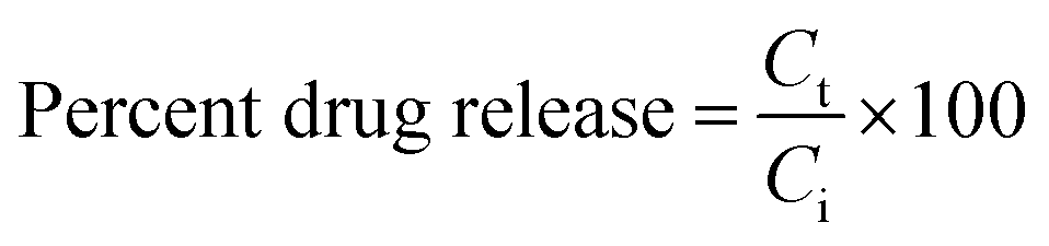
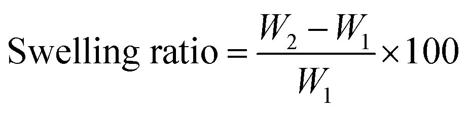 | (1) |
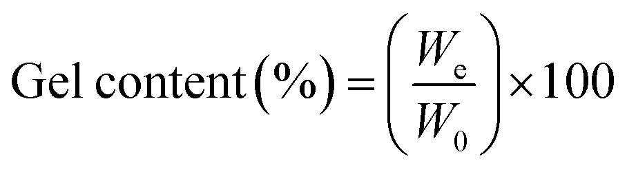
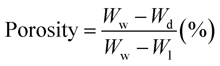
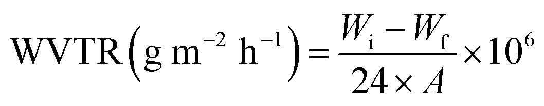
2.3. Hydrogel characterization
 | (2) |
 | (3) |
 | (4) |
 | (5) |
2.4. General method for preparation of Ag2O/SiO2 nanoparticle
Dissolve 1.18 g of AgNO3 in a minimum amount of water, then add 1 ml of ammonia solution. In another container, 6.75 g of sodium silicate was mixed in 25 ml of distilled water. The two solutions were added and stirred to obtain a homogeneous solution. The solution was transferred to a Beaker and dried at 150 °C to obtain a white and a porous solid. The solid was then powdered using a mortar. A graphical depiction of the current preparation of Ag2O/SiO2 has been shown in Fig. 1.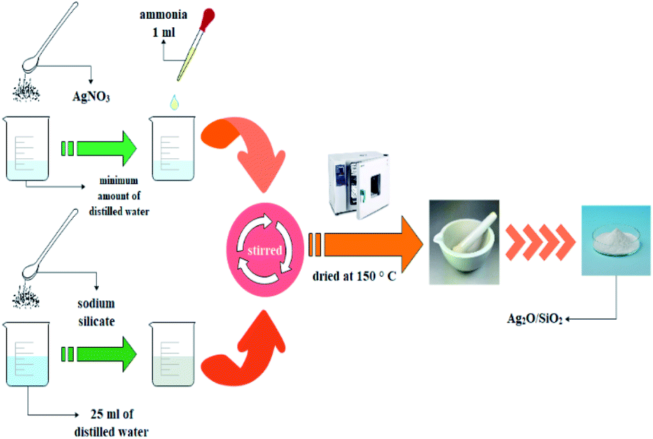 | ||
| Fig. 1 Stepwise of preparation of Ag2O/SiO2 nanoparticle. | ||
2.5. General procedure for preparation of CS/PVA/SA hydrogels
To prepare the CS/PVA/SA hydrogels, the first 2 g of chitosan was dissolved in 100 ml of 1% acetic acid at 60 °C, after that the solution was filtered (2% chitosan solution). Then, 1 g of sodium alginate was dissolved in 100 ml of deionized water (1% sodium alginate solution). In another container, 5 g of polyvinyl alcohol was dissolved in 100 ml of deionized water at 85 °C (5% polyvinyl alcohol solution).The solutions of chitosan, sodium alginate and polyvinyl alcohol were then mixed in 2:2:1, respectively. First, 2% chitosan solution was added dropwise to sodium alginate solution for 2 hours. Then 5% polyvinyl alcohol solution was added dropwise to sodium alginate-chitosan solution for 1 hour. The solution is stirred for 4 hours. An appropriate number of Ag2O/SiO2 nanoparticles and curcumin was added to the obtained solution in the proportions of Table 1. In samples above 20% of nanoparticles, the polymerization process of the hydrogel was disrupted and as the percentage of nanoparticles increased, the synthesized hydrogel was not suitable for biological and mechanical tests, so the maximum percentage of nanoparticles in the hydrogel was selected 20%. It should be noted that the total weight of the solution was considered to be 13 g, in which 10 g of polymer and 3 g of nanoparticles with different weight percentages (0, 5, 10, 15, and 20 wt% of Ag2O/SiO2) are combined. After mixing for 1 hour, it was poured into a Petri dish and dried at 50 °C for 24 hours as shown in Fig. 2.
| Description | Polymer (g) | Ag2O/SiO2 (g) | Curcumin (g) |
|---|---|---|---|
| 0 wt% Ag2O/SiO2 | 10 | 0 | 3 |
| 5 wt% Ag2O/SiO2 | 10 | 0.65 | 2.35 |
| 10 wt% Ag2O/SiO2 | 10 | 1.3 | 1.7 |
| 15 wt% Ag2O/SiO2 | 10 | 1.95 | 1.05 |
| 20 wt% Ag2O/SiO2 | 10 | 2.6 | 0.4 |
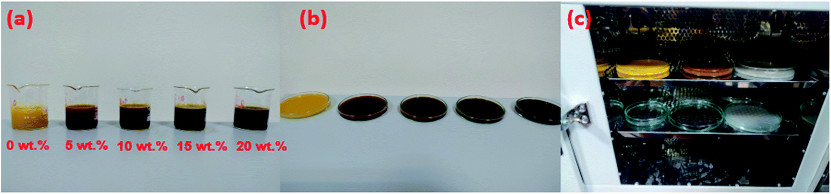 | ||
| Fig. 2 Mixing polymer with a certain weight percentage of nanoparticles (a) accurate measurement of solutions (b) transferred to Petri dishes (c) dried at 50 °C for 24 hours. | ||
A graphical depiction of the current preparation of CS/PVA/SA hydrogels has been shown in Fig. 3.
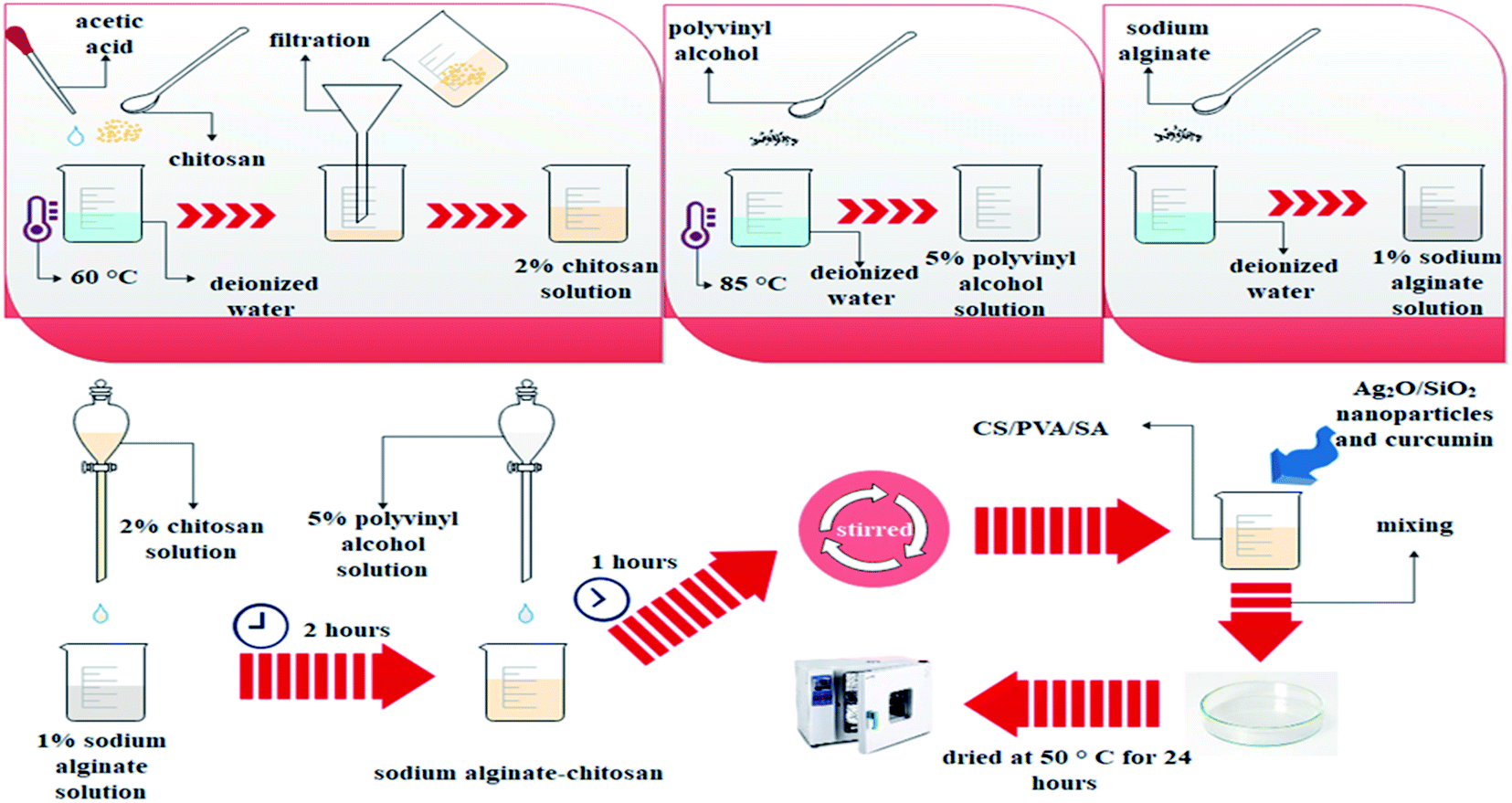 | ||
| Fig. 3 Stepwise of preparation of CS/PVA/SA hydrogels. | ||
3. Results and discussion
In this part, the results of FT-IR spectroscopy, XRD, SEM, AFM, EDS, Antibacterial test, and biological and mechanical properties of mesoporous (CS/PVA/SA-curcumin-Ag2O/SiO2) composites including (0 wt%, 5 wt%, 10 wt%, 15 wt%, and 20 wt% of Ag2O/SiO2) are reported. In this article, mechanical tests cover tensile tests, fracture toughness, elastic modulus, and hardness evaluation.3.1. Results of FT-IR spectroscopy
The Fourier-transform infrared spectra of (a) chitosan, (b) sodium alginate, (c) polyvinyl alcohol, (d) CS/PVA/SA hydrogels (without Ag2O/SiO2 NPs and curcumin) are shown in Fig. 4. For chitosan (Fig. 4a) the absorption peak at 3440 cm−1 is due to the stretching vibration of the O–H bond. The primary amines have two peaks in 3500–3300 cm−1 is corresponding to the stretching vibrational absorptions of N–H bond, but that peak overlaps with the broad O–H peak. However, the absorption peak at 1641 cm−1 is related to the bending vibrational absorptions of N–H primary amines. The peaks at 1435 cm−1 correspond to bending vibrational absorptions of CH2. Finally, the stretching vibrational peak at 1084 cm−1 is related to the C–O.103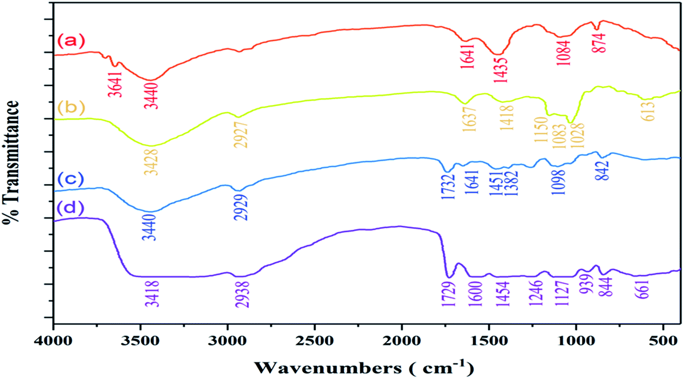 | ||
| Fig. 4 Demonstration of comparative FT-IR spectra of (a) chitosan, (b) sodium alginate, (c) polyvinyl alcohol, (d) CS/PVA/SA hydrogels (without Ag2O/SiO2 NPs and curcumin). | ||
For sodium alginate (Fig. 4b), the characteristic peak at 3428 cm−1 is related to the stretching vibrational absorptions of O–H. The signal that appeared at 2927 cm−1 is corresponding to the stretching vibration of the aliphatic C–H bonds. The asymmetric peaks at 1637 cm−1 and 1418 cm−1 correspond to the sodium carboxylate. The peak at approximately 1028–1150 cm−1 is attributed to the C–O bonds. In the spectrum of polyvinyl alcohol (Fig. 4c), the broad peak at 3440 cm−1 is related to the stretching vibrational absorptions of O–H. Moreover, the peaks at 2929 cm−1 assigned to the stretching vibration of the aliphatic C–H bonds. The signals that are absorbed in 1641–1732 cm−1 are related to carbonyl group (C![[double bond, length as m-dash]](https://www.rsc.org/images/entities/char_e001.gif) O) from the tautomerization of polyvinyl alcohol. The stretching vibrational peak at 1098 cm−1 is related to the C–O.
O) from the tautomerization of polyvinyl alcohol. The stretching vibrational peak at 1098 cm−1 is related to the C–O.
The spectrum of CS/PVA/SA hydrogels (Fig. 4d), shows the broad peak at 3418 cm−1 related to O–H bond, indicating the existence of strong intermolecular and intramolecular hydrogen bonding illustrated in (Fig. 5). The spectrum shows some peaks at 2938, 1729, 1600, 1454 and a strong peak between 1127 and 1246 cm−1 correlated to stretching vibration of the aliphatic C–H bonds, stretching vibration of CO, stretching CO bonds of sodium carboxylate, and stretching vibrational of C–O, respectively. The FT-IR spectra of the (a) curcumin, (b) Ag2O/SiO2 NPs, (c) CS/PVA/SA hydrogels (without Ag2O/SiO2 NPs and curcumin), (d) CS/PVA/SA hydrogels (0 wt% of Ag2O/SiO2) and, (e) CS/PVA/SA hydrogels (20 wt% of Ag2O/SiO2) were analyzed and the outcomes were displayed in Fig. 6. In the spectrum of curcumin (Fig. 6a), the wide peaks about 3414 cm−1 owing to the stretching vibrations of O–H bonding.
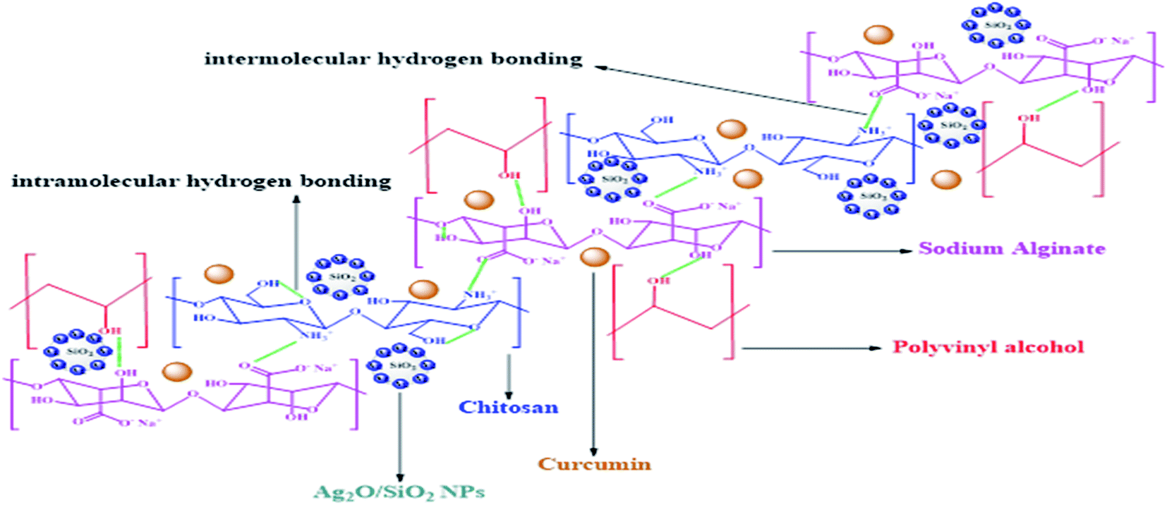 | ||
| Fig. 5 Schematic illustration of the hydrogen bonding of CS/PVA/SA hydrogels (with Ag2O/SiO2 NPs and curcumin). | ||
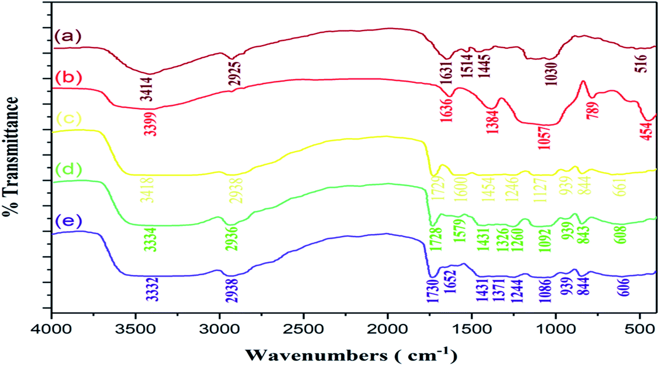 | ||
| Fig. 6 Demonstration of comparative FT-IR spectra of (a) curcumin, (b) Ag2O/SiO2NPs, (c) CS/PVA/SA hydrogels (without Ag2O/SiO2NPs and curcumin), (d) CS/PVA/SA hydrogels (0 wt% of Ag2O/SiO2) and, (e) CS/PVA/SA hydrogels (20 wt% of Ag2O/SiO2). | ||
The signal that appeared at 2925 cm−1 is corresponding to the aliphatic C–H bonds. The peak that place about 1631 cm−1 due to bending vibration of CO bonding. The peaks of 1601 and 1445 cm−1 are related to the aromatic ring. Additionally, the peak of 1030 cm−1 related to C–O stretching vibrational.
In the FT-IR spectra of Ag2O/SiO2 NPs (Fig. 6b), the signal in 3399 cm−1 is due to the Si–OH bond.104 Correspondingly, the peak at 1636 cm−1 is related to the bending vibration of H2O molecules, and the peak appeared around of 1057 cm−1 is related to the stretching vibration of Si–O bonding. The sharper peak at 1384 cm−1 and the broader one at 454 cm−1 is due to the Ag–O bond vibration.105
The FT-IR spectra of CS/PVA/SA hydrogels (0 wt% of Ag2O/SiO2) (Fig. 6d), the signal appeared around 1579 and 1431 cm−1 due to aromatic ring corresponding to the curcumin. Also, a peak of 1260 cm−1 correlated to phenols C–O bonding. This peak is demonstrated curcumin in CS/PVA/SA hydrogels (0 wt% of Ag2O/SiO2).
3.2. Investigation of structure and phase determination of polymer/metal nanoparticles by XRD
The crystalline structure of the Ag2O/SiO2 nanoparticles, CS/PVA/SA, and CS/PVA/SA-curcumin-Ag2O/SiO2 was studied by XRD characterization in (Fig. 7).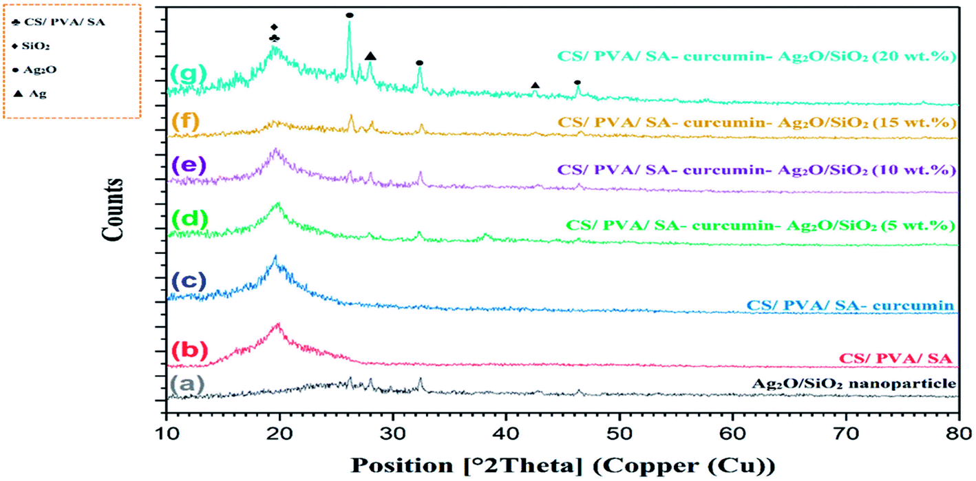 | ||
| Fig. 7 XRD pattern of (a) Ag2O/SiO2 nanoparticle, (b) CS/PVA/SA, (c) CS/PVA/SA-curcumin, (d) CS/PVA/SA-curcumin-Ag2O/SiO2 (5 wt%), (e) CS/PVA/SA-curcumin-Ag2O/SiO2 (10 wt%), (f) CS/PVA/SA-curcumin-Ag2O/SiO2 (15 wt%), (g) CS/PVA/SA-curcumin-Ag2O/SiO2 (20 wt%). | ||
Fig. 7a displays a wide peak between 20 and 30° 2-theta which is characteristic of the amorphous structure of SiO2.106 The peaks at 26.13, 27.99, 32.37, 42.51, and 46.35 indicated the formation of a crystalline structure of the Ag2O/SiO2 nanoparticles.107 The average size for the designed Ag2O/SiO2 nanoparticles was measured using the Debye–Scherrer formula. The average size of the Ag2O/SiO2 nanoparticles thus taken from this equation was determined to be 82 nm in excellent agreement with that seen in the (FE-SEM) examinations (Fig. 8a). The obtained a wide and sharp peak at 19.77 related to CS/PVA/SA in (Fig. 7b–g).
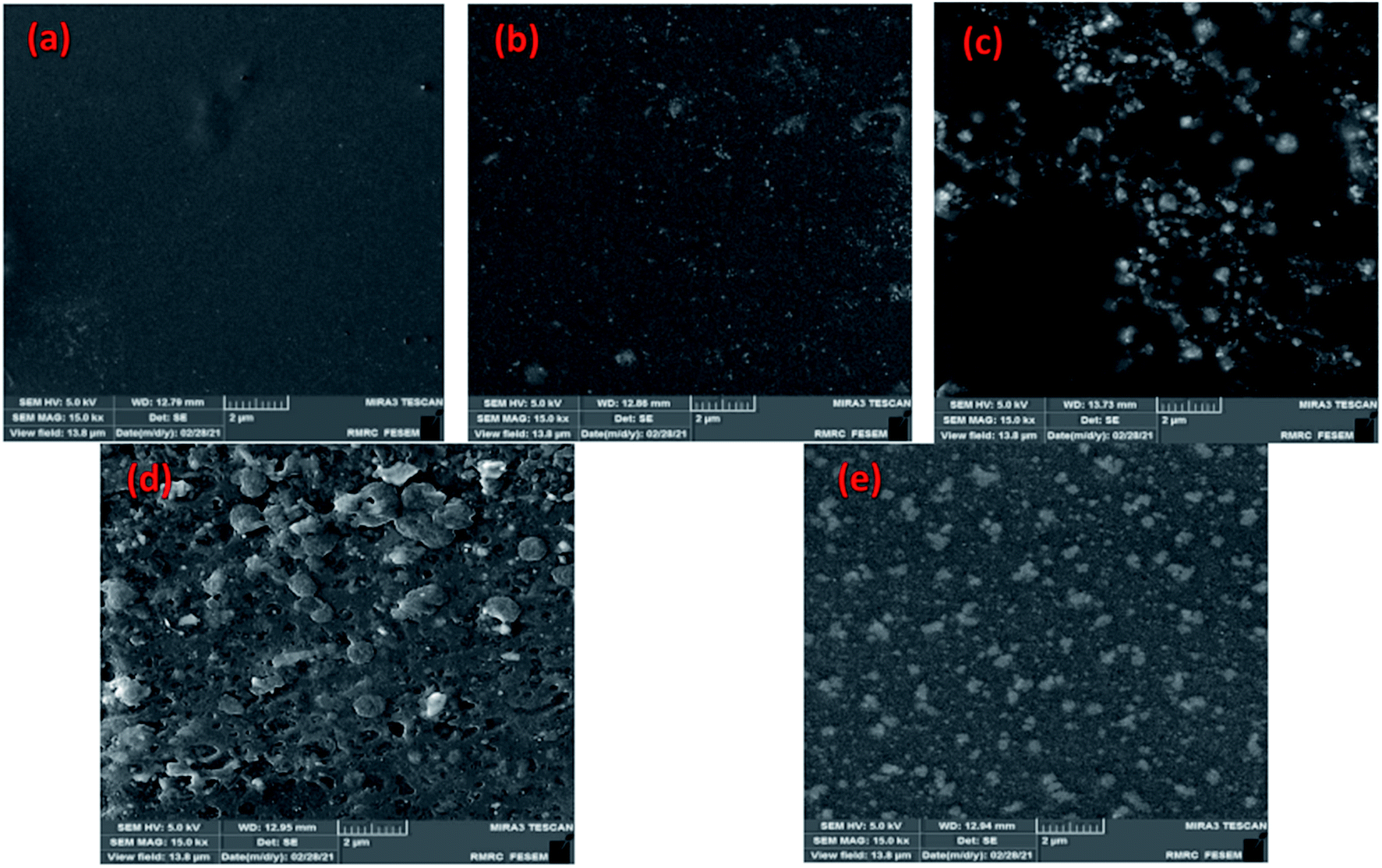 | ||
| Fig. 8 SEM of the fabricated CS/PVA/SA hydrogels functionalized with mesoporous Ag2O/SiO2 and curcumin bio-nanocomposite scaffolds containing (a) 0 wt% (b) 5 wt%, (c) 10 wt%, (d) 15 wt%, and (e) 20 wt% of Ag2O/SiO2 nanoparticles within the scale of 2 microns. | ||
3.3. Investigation of morphology and structure of composite scaffolds using SEM
As shown in Fig. 8(a–e), SEM images well show the percentage increase of Ag2O/SiO2 nanoparticles in nanocomposites. In Fig. 8(b–e), Ag2O/SiO2 nanoparticles are attached to the polymer as reinforcements. Fig. 8a–e shows the surface of the samples, these surfaces (b–e) have a porous morphology.This clearly shows that this structure is proper for use as a wound dressing. Because with the increase of Ag2O/SiO2, the antibacterial properties increase. It is also clear that the sample has increased in porosity and porosity size by 20 wt% (with a higher weight percentage of Ag2O/SiO2) than in the 0 wt% sample. As can be seen in figures (b–e), the structure of the biocomposites consists of irregularly interconnected nanoparticles in a composite structure that plays an essential role in wound healing. Fig. 8 demonstrates the polymeric matrix corresponding to a different weight percentage (0 wt%, 5 wt%, 10 wt%, 15 wt%, and 20 wt% of Ag2O/SiO2). It can be observed and concluded that the free surfaces of samples have a porous morphology.
The SEM images of mesoporous Ag2O/SiO2 nanoparticles were displayed in Fig. 9a. The average size of the Ag2O/SiO2 nanoparticles is 80 nm. The nanoparticle size from the SEM was so close to the estimated size from XRD techniques. These images confirm the formation of the three-dimensional structure of Ag2O/SiO2 nanoparticles. Fig. 9b shows the channels created on the surface of the hydrogel, which is the result of the release of solvents in the drying process of the hydrogel. The average diameter of the channels is estimated between 175–354 nm. The presence of channels increases the contact surface of the nanoparticles, thus increasing the wound dressing efficiency.
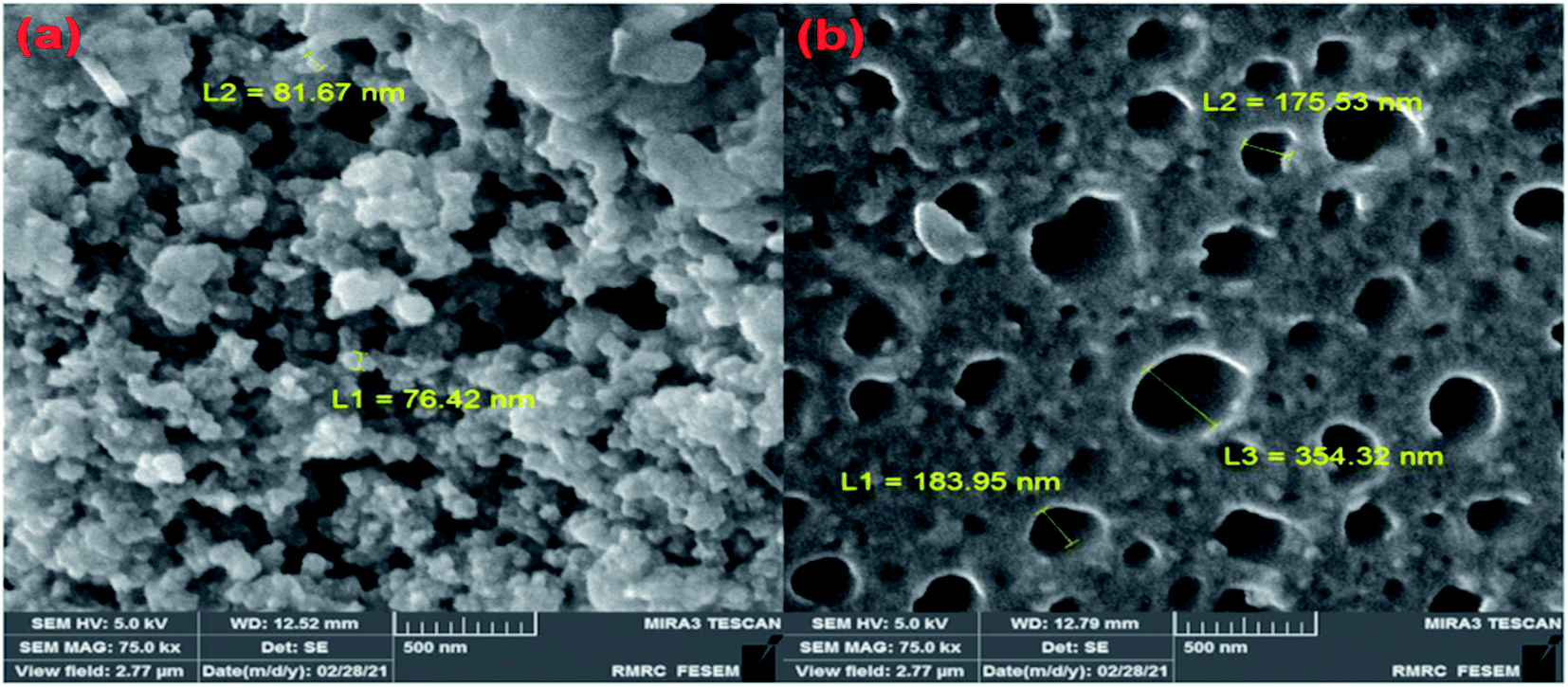 | ||
| Fig. 9 FE-SEM image of (a) mesoporous Ag2O/SiO2 nanoparticle (b) CS/PVA/SA hydrogels channels. | ||
3.4. EDS spectroscopy of CS/PVA/SA hydrogels
EDS spectroscopy is an analytical method utilized to examine the structure of a sample. EDS is an add-on in SEM devices to detect the percentage of elements in solid samples. This analysis can detect the type of element and its weight or atomic percentage using the unique X-ray energy emitted from the sample. In the EDS analysis, it will be possible to identify the constituent elements of the sample in a semi-quantitative manner. The descriptive capabilities of this method are generally based on the general principle that each element has a unique atomic structure that enables a unique set of peaks in its X-ray spectrum.As shown in (Fig. 10a–e), the main elements in fabricating this wound dressing are nitrogen, carbon, oxygen, silver, and silicon. Also, other elements observed in the EDS spectrum are related to chitosan and sodium alginate. According to Fig. 10, with increasing the number of nanoparticles in the hydrogels by (0 wt%, 5 wt%, 10 wt%, 15 wt%, and 20 wt%), respectively, the amount of 0%, 0.29%, 0.41%, 0.44%, and finally 1.33% of silver is observed.
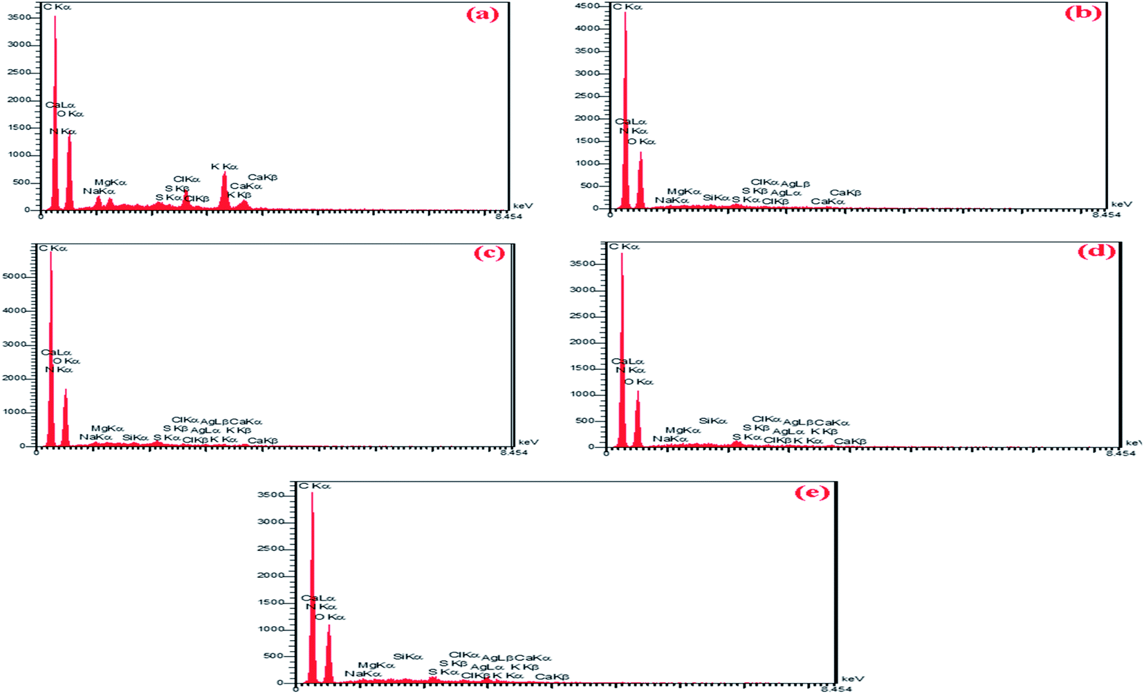 | ||
| Fig. 10 EDS spectrum of CS/PVA/SA hydrogels with different composition fractions of Ag2O/SiO2 NPs (a) 0 wt% (b) 5 wt%, (c) 10 wt%, (d) 15 wt%, and (e) 20 wt%. | ||
3.5. Investigation of surface roughness by AFM
In surface studies of nanocomposite samples to investigate the relationship between hardness and roughness of the samples, the results of structural and microscopic examination of the samples showed that the addition of Ag2O/SiO2 increased the porosity and surface roughness of the samples. Nanoporous compounds are one of the most important groups of nanostructures.108Advantages such as high active surface area, high reactivity, and insulating features allow the application of these compounds in the field of wound dressings in tissue engineering. The interaction of cavities with host molecules can be investigated based on supermolecular chemistry. By examine the physicochemical environment of cavities, unique properties can be provided in the interaction with guest molecules and the structure can be optimized for further applications. In Fig. 11, the images were taken from samples of (0, 5, 10, 15, and 20 wt% of Ag2O/SiO2) with a length and width of between 5 to 10 microns, then their diagrams of each surface were drawn. The AFM image results show that the increasing of Ag2O/SiO2 increases the porosity of the surface of nanocomposite samples.
 | ||
| Fig. 11 AFM analysis of the fabricated CS/PVA/SA hydrogels functionalized with mesoporous Ag2O/SiO2 and curcumin nanoparticles containing (a) 0 wt%, (b) 5 wt%, (c) 10 wt%, (d) 15 wt%, and (e) 20 wt% of Ag2O/SiO2 NPs within the scale of 5 to 10 microns. | ||
3.6. Mechanical test results
According to Fig. 12a, it can be seen that with improving and increasing the weight fraction of Ag2O/SiO2 nanoparticles in the structure of bio-nano composite, the hardness of the samples is increased due to the specificity of silver. Accordingly, the hardness for specimen with 0 wt% is about 0.8 N mm−2, while for the specimen with 20 wt% of Ag2O/SiO2, it is approximately 3.7 N mm−2, which increases more than four times. Also, it has been shown that by increasing the weight percentage of Ag2O/SiO2 nanoparticles to the base polymer, the intermolecular forces among the nanoparticles increase. In terms of the nanostructure, the mechanism of binding of Ag2O/SiO2 and curcumin to the polymer is due to the relatively hard mechanical properties of Ag2O/SiO2. Due to the spherical shape of Ag nanoparticles, they have a high Young's modulus and ultimate stress. Subsequently, the bioceramic part of the fabricated material results in an enhancement in mechanical properties of the bio-nano composite, it can be concluded that the addition of Ag2O/SiO2 and curcumin nanoparticles has a threshold limit for the high percentage of the additive particles in the polymer. As can be observed in Fig. 12a, the hardness and elastic modulus diagrams describe an increased pattern through increasing the weight fraction of Ag2O/SiO2 nanoparticles. For Young's modulus value, for the sample with 0 wt%, it is estimated to be about 75 MPa and for the sample containing 20 wt% Ag2O/SiO2, it is estimated to be about 33 MPa. The degradation behavior of CS/PVA/SA hydrogels functionalized with Ag2O/SiO2 and curcumin was investigated, so five scaffolds with different weight fractions of Ag2O/SiO2 were immersed in PBS and SBF. To determine the optimal length of time for the swelling ratio, samples of the same size and weight with different percentages of Ag2O/SiO2 were examined. Different samples of hydrogels were immersed in the solution and then at certain periods their swelling ratio was obtained, after three weeks no increase in swelling ratio was observed, thus the maximum swelling percentage occurred in three weeks.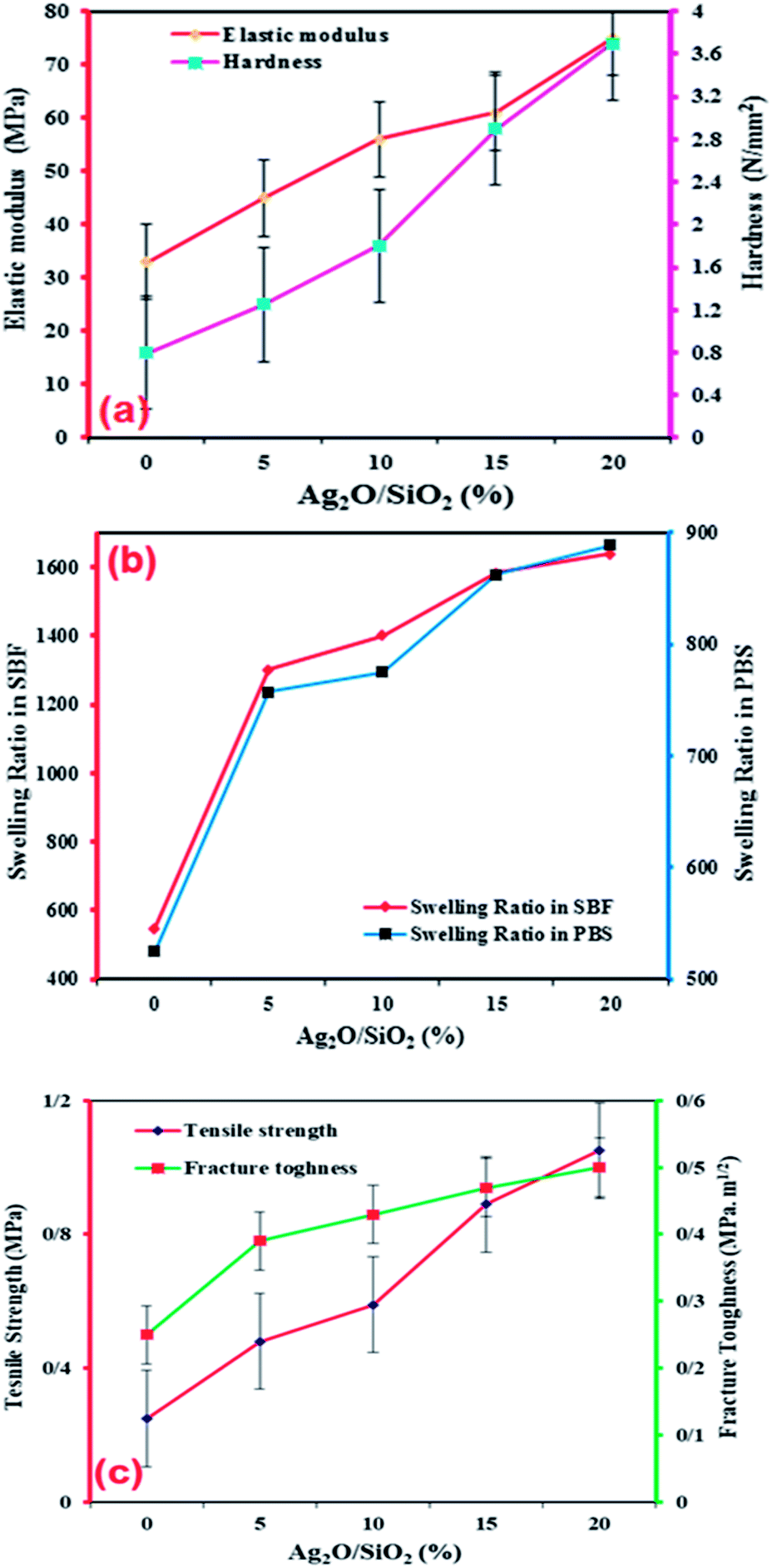 | ||
| Fig. 12 Investigation of (a) elastic modulus-hardness (b) swelling ratio in SBF and PBS (c) tensile strength-fracture toughness of bio nanocomposites with (0 wt%, 5 wt%, 10 wt%, 15 wt%, 20 wt% of Ag2O/SiO2). | ||
Finally, the scaffolds with 0 wt%, 5 wt%, 10 wt%, 15 wt%, and 20 wt% of Ag2O/SiO2 nanoparticles are immersed in the above solutions for three weeks, and then the weight of each specimen is measured using a digital scale in both dry and wet conditions. As depicted in Fig. 12b, the bio-nano composite samples submerged in PBS are heavier than those immersed in the SBF. As shown in Fig. 12b, the swelling ratio of mesoporous bio-nano composite samples submerged in PBS is equal to 525 and 888 for 0 wt% and 20 wt% of Ag2O/SiO2 respectively, Also, for the bio-nano composite samples submerged in SBF, the swelling ratio is about 547.05 and 1639.13 for the sample with 0 wt% and 20 wt% of Ag2O/SiO2 nanoparticles respectively.
All details of the swelling ratio for all weight fractions nanocomposites are presented in Table 2. As can be seen from the results, the increase in the percentage of nanoparticles increases the swelling ratio as well. Due to the use of silica in the synthesis of nanoparticles, the porous structure of silica has increased the adsorption of the solution. The porous structure of silica has pores at the nanoscale, at first, the adsorption rate is very high and after time the adsorption rate of the solution decreases, so the maximum duration of swelling was observed for three weeks. First, the adsorption of the solution is done by larger cavities at high speed, then as the cavities become smaller, the electrostatic repulsions between the wall of the cavities and the solution increase, and the adsorption speed decreases, and more time are required to fill all of the small cavities.
| Specimen | pH | Wet sample weight (g) | Dry sample weight (g) | Swelling Ratio |
|---|---|---|---|---|
| 0 wt%-SBF | 9 | 11.0 | 017.0 | 547.05 |
| 5 wt%-SBF | 9 | 28.0 | 0.02 | 1300 |
| 10 wt%-SBF | 9 | 0.33 | 0.022 | 1400 |
| 15 wt%-SBF | 9 | 37.0 | 0.022 | 1581.81 |
| 20 wt%-SBF | 9 | 0.40 | 0.023 | 1639.13 |
| 0 wt%-PBS | 6 | 05.0 | 008.0 | 525 |
| 5 wt%-PBS | 6 | 0.06 | 0.007 | 757.14 |
| 10 wt%-PBS | 6 | 0.07 | 0.008 | 775 |
| 15 wt%-PBS | 6 | 0.077 | 0.008 | 862.5 |
| 20 wt%-PBS | 6 | 0.089 | 0.009 | 888.88 |
As we mentioned in the previous section to calculate the mechanical properties, a tensile strength test with (SANTAM machine) manufactured in Iran was used. For this purpose, each cube sample with a length and width of 10 mm and a thickness of 1 mm is prepared and loaded at a rate of 0.2 mm min−1. As shown in Fig. 12c the tensile strength for the sample with 0 wt% and 20 wt% of Ag2O/SiO2 is 0.25 and 1.05 MPa which shows an increase of more than four times. This increase can be due to the high strength of silver. Also, the fracture toughness of samples was investigated, the fracture toughness of samples with 0 wt% and 20 wt% of Ag2O/SiO2 is 0.25 and 0.50 MPa m1/2 which shows an increase of two times. Fig. 13 shows the engineering stress–strain curve of the nanocomposite with 0–20 wt% of Ag2O/SiO2 nanoparticles. As can be seen from the stress–strain curve, the tensile strength of the sample of 20 wt% (Ag2O/SiO2) is higher than other samples due to the inherent nature of silver.
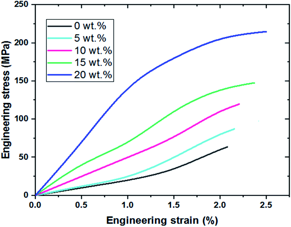 | ||
| Fig. 13 Engineering stress–strain curve of the nanocomposite with 0∼20 wt% (Ag2O/SiO2). | ||
3.7. Antibacterial test results
A bacterium is a simple single-celled organism that lacks membrane-bound intracellular organs such as the nucleus, Golgi apparatus, endoplasmic reticulum, and mitochondria.108 Thus, the metabolic and biosynthetic activities of bacteria take place within the cell membrane or cytoplasm.109 Because the cells of parasites, fungi, humans, and animals are organized and have a membrane-bound nucleus, these organisms act as eukaryotes (true nuclei), and bacteria without the true nuclei are classified as prokaryotes.110 Classifies bacteria based on species, size, shape, and metabolism (aerobic, anaerobic).111Important bacteria in medicine are mostly rod-shaped, round, and spiral.112 One type of bacterial classification is based on the characteristics of Gram staining. When the stained bacterium is blue or purple under a light microscope, it is a Gram-positive bacterium, and if it is red or pink, it is a Gram-negative bacterium. Clinically, Gram-positive bacteria are abundant on the skin and mucous membranes.113 The most common in medicine are Staphylococcus, Streptococcus, and Pneumococcus. Gram-positive bacteria are more sensitive to lubricants than Gram-negative bacteria such as lysozyme and penicillin G because they lack an outer membrane that protects the cell wall from access by these agents.114 The most important Gram-negative bacteria are medically bacilli or diplococci and often reside in the gastrointestinal tract.115 Gram-negative bacteria are generally more sensitive to the lubricating properties of antibodies and complement than Gram-positive bacteria. This is due to the presence of an outer membrane, which is the target of membranes that invade the membrane after the complement has collapsed.116 Acinetobacter baumannii is an opportunistic bacterial pathogen primarily correlated with hospital-acquired infections. Staphylococcus epidermidis is a general symbiont bacterium that can become infectious once inside the human host. They are among the most usual causes of nosocomial infection in the United States and can lead to dangerous complications.117 Proteus mirabilis is a Gram-negative, facultatively anaerobic, rod-shaped bacterium. It shows swarming motility and enzyme activity.118 P. mirabilis causes 90% of all Proteus infections in humans. It is widely distributed in soil and water. Proteus mirabilis can migrate across the surface of solid media or devices using a variety of cooperative group motility known as swarming. Proteus mirabilis is most frequently associated with infections of the urinary tract, especially in complicated or catheter-associated urinary tract infections.119 Fig. 14 shows the results of antibacterial activity testing of various nanostructures synthesized in this study (0 wt%, 5 wt%, 10 wt%, 15 wt%, 20 wt% of Ag2O/SiO2) by disk method on three types of bacteria including Acinetobacter baumannii, Staphylococcus epidermidis, and Proteus mirabilis in a colony volume of 100 μl. Fig. 14(a–c) show disk test plates for five nanocomposites fabricated in different weight percentages of Ag2O/SiO2, in which the growth inhibition zone is visible. Table 3 shows the size of the growth inhibition halos. Fig. 14a–c show disk test plates for five nanocomposites fabricated in different weight percentages of Ag2O/SiO2, in which the growth inhibition zone is visible. It should be noted that the table numbers are based on the one-way halo of no growth, i.e., the distance of the sample to the beginning of bacterial growth. The numbers for the bacterium Proteus mirabilis are two.
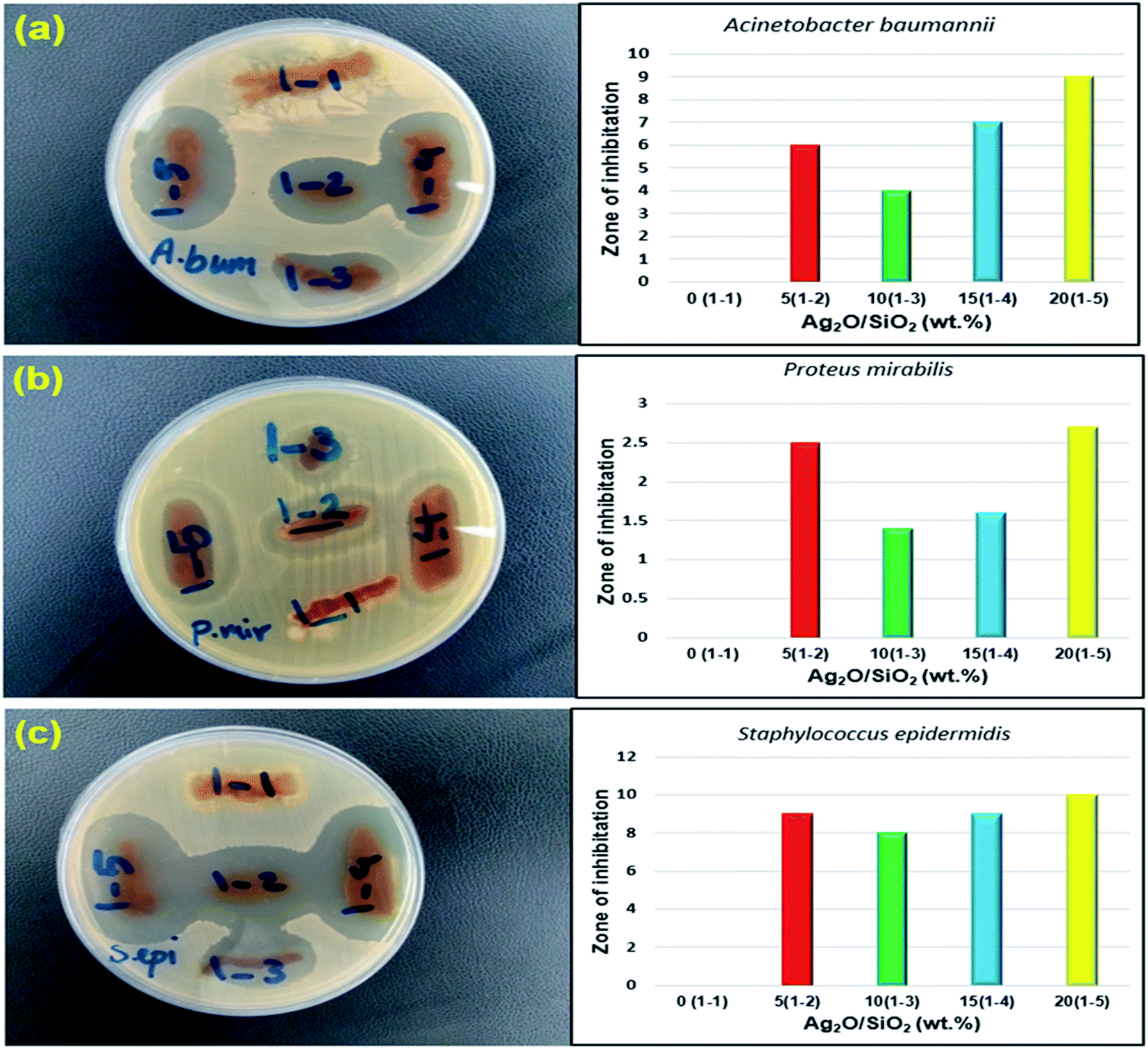 | ||
| Fig. 14 Results of antibacterial activity of nanostructures against (a) Acinetobacter baumannii (b) Proteus mirabilis (c) Staphylococcus epidermidis. | ||
| Test microorganism | 1–1 (0 wt%) | 1–2 (5 wt%) | 1–3 (10 wt%) | 1–4 (15 wt%) | 1–5 (20 wt%) |
|---|---|---|---|---|---|
| Acinetobacter baumannii (ATCC BAA-747) | — | 6 | 4 | 7 | 9 |
| Proteus mirabilis (ATCC 43071) | — | 2.5/6 | 1.4/5 | 1.6/6 | 2.7/7 |
| Staphylococcus epidermidis (CIP 81.55) | — | 9 | 8 | 9 | 10 |
The first number is the growth inhibition aura and the second number is the growth reduction aura. Antibiogram results of antibiotic controls on the tested strains are shown in Table 4.
| Antibiotics | Rifampin | Gentamicin | ||
|---|---|---|---|---|
| DD | MIC | DD | MIC | |
| Proteus mirabilis (ATCC 43071) | 9 | 15.63 | 20 | 31.25 |
| Staphylococcus epidermidis (CIP 81.55) | 27 | 1.95 | 45 | 1.95 |
| Acinetobacterbaumannii (ATCC BAA-747) | 8 | 7.81 | 17 | 3.90 |
It should be noted that the concentration used in the first stage is the antibiotics rifampin (5 μg per disc) and gentamicin (10 μg per disc), and MIC in terms of micrograms per milliliter (μg ml−1).
3.8. Hydrogels
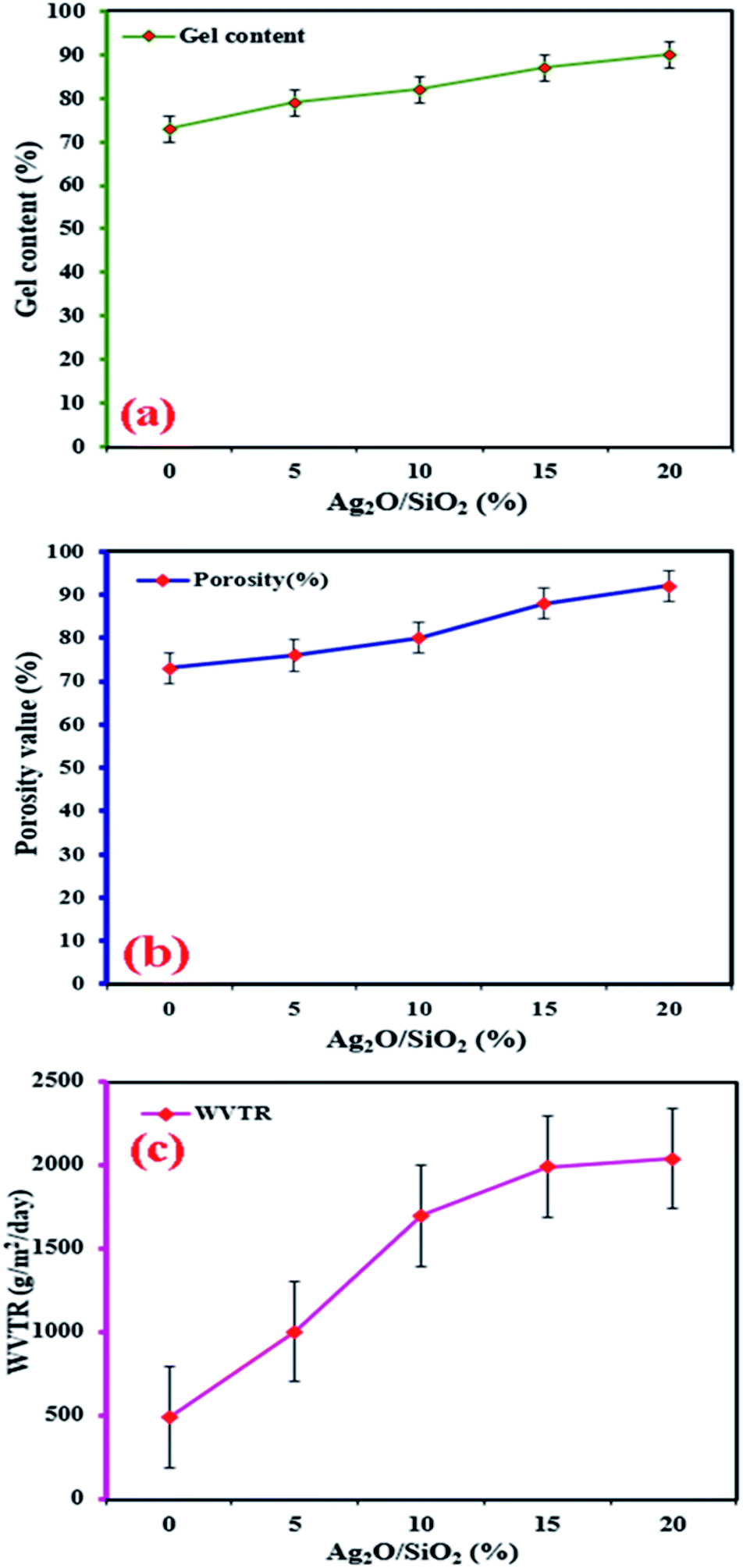 | ||
| Fig. 15 Investigation of (a) gel content, (b) porosity, (c) hydrogel water vapor transmission rate (WVTR). | ||
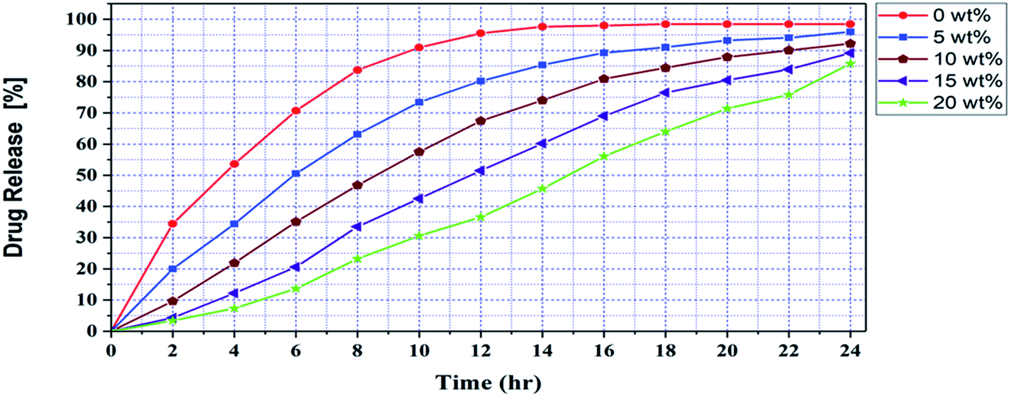 | ||
| Fig. 16 Drug release behavior of CS/PVA/SA hydrogels with different composition fractions of Ag2O/SiO2 NPs. | ||
According to Fig. 16, in hydrogels without nanoparticles, the release of curcumin was very fast and reached its maximum in 16 hours, and after that, we did not see a significant release of curcumin. Also, with the increase of the percentage of hydrogel nanoparticles, the release of the curcumin was slow, continuous, and balanced. Due to the porosity of the nanoparticles and the bonds formed between the curcumin and the nanoparticles, with the increase of the percentage of hydrogel nanoparticles, the release of the curcumin was slow, continuous, and balanced. On the other hand, with increasing the percentage of nanoparticles due to the presence of these bonds, the percentage of drug release has decreased and some curcumin molecules are trapped in the porosity of nanoparticles and hydrogels and are not completely release from the hydrogel structure. However, increasing the percentage of nanoparticles to 20 wt% has increased wound healing efficiency.
4. Conclusions
The use of silver nanoparticles stabilized on a silica substrate has created a porous, three-dimensional structure that has increased the surface area of nanoparticles in contact with the environment, resulting in increased antibacterial properties. Besides, X-ray analysis showed a well porous and three-dimensional state of Ag2O/SiO2 nanoparticles formed. Silver nanoparticles are very active and due to their high surface activity have a high tendency to migrate and agglomerate, which tends to migrate and agglomerate reduces their activity. By stabilizing silver nanoparticles on a silica substrate, migration and agglomeration of nanoparticles are prevented. Also, increasing the percentage of the nanoparticles increased the antibacterial performance of the samples. This increase in the percentage of nanoparticles did not reduce the antibacterial performance of the samples, one of the reasons being the stabilization of silver nanoparticles on the silica and preventing agglomeration and migration of silver nanoparticles. Since flexibility is one of the most important factors in wound dressings, the presence of groups with the ability to establish hydrogen bonding in the nanoparticle structure creates a bond between nanoparticles and polymer constituents and thus improves the mechanical properties of wound dressings.The mechanical results obtained with the tensile test showed that with the increasing of Ag2O/SiO2, the mechanical properties, as well as the healing properties of the wound dressing, have increased significantly. Therefore, we can conclude the nanocomposite with 20 wt% Ag2O/SiO2 is the best sample in terms of strength.
Due to the importance of biocompatibility of wound dressing materials, the combined use of green and biocompatible polymers has been of particular importance in this study. The biocompatibility of wound dressing ingredients has helped the wound to heal faster. Also, the porous structure of the prepared hydrogel has made the wound dressing effective. The porous structure of nanoparticles and hydrogels caused the continuous and regular release of curcumin during the wound healing time. According to the results obtained from the drug release analysis, increasing the percentage of nanoparticles to 20% caused a trap of some curcumin, but on the other hand, with increasing the percentage of nanoparticles, the release of curcumin was continuous, slow and balanced, which is an important factor in wound dressing effectiveness.
The presence of curcumin in the wound dressing due to its anti-inflammatory properties helps to heal the wound as soon as possible.
Funding
The authors received no financial support for the research, authorship, and publication of this article.Conflicts of interest
No conflict of interest exists in the submission of this article, and the article is approved by all authors for publication.Acknowledgements
The authors are thankful to the Iranian Nanotechnology Development Committee for their financial support and the University of Kashan for supporting this work by Grant No. 1073251/3 and the Micro and Nanomechanics Laboratory by Grant No. 14002021/1.References
- Y. Yang, H. Chen, X. Zou, X.-L. Shi, W.-D. Liu, L. Feng, G. Suo, X. Hou, X. Ye, L. Zhang, C. Sun, H. Li, C. Wang and Z.-G. Chen, ACS Appl. Mater. Interfaces, 2020, 12, 24845–24854 CrossRef CAS PubMed.
- J. Guo, C. Xiao, J. Gao, G. Li, H. Wu, L. Chen and L. Qian, Tribol. Int., 2021, 159, 107004 CrossRef CAS.
- J. Guo, J. Gao, C. Xiao, L. Chen and L. Qian, Friction, 2021, 9 DOI:10.1007/s40544-021-0501-9.
- N. Gao, L. Tang, J. Deng, K. Lu, H. Hou and K. Chen, Appl. Acoust., 2021, 175, 107845 CrossRef.
- N. Gao, X. Guo, J. Deng, B. Cheng and H. Hou, Appl. Acoust., 2021, 173, 107694 CrossRef.
- X. Zhu, F. Lin, Z. Zhang, X. Chen, H. Huang, D. Wang, J. Tang, X. Fang, D. Fang, J. C. Ho, L. Liao and Z. Wei, Nano Lett., 2020, 20, 2654–2659 CrossRef CAS PubMed.
- K. Zhang, Z. Yang, X. Mao, X.-L. Chen, H.-H. Li and Y.-Y. Wang, ACS Appl. Mater. Interfaces, 2020, 12, 55316–55323 CrossRef CAS PubMed.
- H. Guan, S. Huang, J. Ding, F. Tian, Q. Xu and J. Zhao, Acta Mater., 2020, 187, 122–134 CrossRef CAS.
- D. Xu, Q. Liu, Y. Qin and B. Chen, Structural Health Monitoring, 2020, 147592172097429 CrossRef.
- H. Zhu, Y. An, M. Shi, Z. Li, N. Chen, C. Yang and P. Xiao, Mater. Lett., 2021, 296, 129837 CrossRef CAS.
- H. Zheng and B. Zuo, J. Mater. Chem. B, 2021, 9, 1238–1258 RSC.
- L. Han, J. Xu, X. Lu, D. Gan, Z. Wang, K. Wang, H. Zhang, H. Yuan and J. Weng, J. Mater. Chem. B, 2017, 5, 731–741 RSC.
- D. Gan, T. Xu, W. Xing, M. Wang, J. Fang, K. Wang, X. Ge, C. W. Chan, F. Ren, H. Tan and X. Lu, J. Mater. Chem. B, 2019, 7, 1716–1725 RSC.
- X. Zhang and Y. Zhang, Int. J. Therm. Sci., 2021, 163, 106826 CrossRef CAS.
- Z. Chen, H. Zhang, X. He, G. Fan, X. Li, Z. He, G. Wang and L. Zhang, BioResources, 2021, 16, 2644–2654 CAS.
- L. Zhang, M. Zhang, S. You, D. Ma, J. Zhao and Z. Chen, Sci. Total Environ., 2021, 780, 146505 CrossRef CAS PubMed.
- F. Guo, S. Wu, J. Liu, Z. Wu, S. Fu and S. Ding, Eng. Fract. Mech., 2021, 248, 107711 CrossRef.
- X. Cao, Z. Huang, C. He, W. Wu, L. Xi, Y. Li and D. Fang, Composite Structures, 2021, 267, 113926 CrossRef.
- S. Mondal, S. Das and A. K. Nandi, Soft Matter, 2020, 16, 1404–1454 RSC.
- S. K. Das, T. Parandhaman and M. D. Dey, Green Chem., 2021, 23, 629–669 RSC.
- Y. Zhang, E. Ren, A. Li, C. Cui, R. Guo, H. Tang, H. Xiao, M. Zhou, W. Qin, X. Wang and L. Liu, J. Mater. Chem. B, 2021, 9, 719–730 RSC.
- S. C. P. Norris, S. M. Delgado and A. M. Kasko, Polym. Chem., 2019, 10, 3180–3193 RSC.
- Y. Li, X. Ren, T. Zhao, D. Xiao, K. Liu and D. Fang, Marine Structures, 2021, 77, 102957 CrossRef.
- P. Feng, H. Chang, X. Liu, S. Ye, X. Shu and Q. Ran, Mater. Des., 2020, 186, 108320 CrossRef CAS.
- G. Xiao, K. Song, Y. He, W. Wang, Y. Zhang and W. Dai, Int. J. Adv. Des. Manuf. Technol., 2021, 115, 1111–1125 CrossRef.
- L. Chen, J. Xu, M. Zhang, T. Rong, Z. Jiang and P. Li, Ceram. Int., 2021, 47, 7511–7520 CrossRef CAS.
- X. Wang, Z. Feng, B. Xiao, J. Zhao, H. Ma, Y. Tian, H. Pang and L. Tan, Green Chem., 2020, 22, 6157–6169 RSC.
- T. S. Welles and J. Ahn, Heliyon, 2021, 7, e07023 CrossRef PubMed.
- A. Farazin, S. Sahmani, M. Soleimani, A. Kolooshani, S. Saber-Samandari and A. Khandan, Ceram. Int., 2021, 47, 18339–18350 CrossRef CAS.
- A. Farazin, M. Mohammadimehr and A. Ghorbanpour-Arani, Struct. Eng., Mech., 2021, 78, 691–702 Search PubMed.
- D. Y. Shin, J.-U. Park, M.-H. Choi, S. Kim, H.-E. Kim and S.-H. Jeong, Sci. Rep., 2020, 10, 16811 CrossRef CAS PubMed.
- D. McCaughan, L. Sheard, N. Cullum, J. Dumville and I. Chetter, Journal of Clinical Nursing, 2020, 29, 2557–2571 CrossRef PubMed.
- V. Kanikireddy, K. Varaprasad, T. Jayaramudu, C. Karthikeyan and R. Sadiku, Int. J. Biol. Macromol., 2020, 164, 963–975 CrossRef CAS PubMed.
- P. Kaiser, J. Wächter and M. Windbergs, Drug Delivery Transl. Res., 2021, 11(4), 1545–1567 CrossRef CAS PubMed.
- Y. Guo, S. Pan, F. Jiang, E. Wang, L. Miinea, N. Marchant and M. Cakmak, RSC Adv., 2018, 8, 8173–8180 RSC.
- M. Tavakolizadeh, A. Pourjavadi, M. Ansari, H. Tebyanian, S. J. Seyyed Tabaei, M. Atarod, N. Rabiee, M. Bagherzadeh and R. S. Varma, Green Chem., 2021, 23, 1312–1329 RSC.
- H. Wang, Z. Xu, M. Zhao, G. Liu and J. Wu, Biomater. Sci., 2021, 9, 1530–1546 RSC.
- L.-H. Fu, C. Qi, M.-G. Ma and P. Wan, J. Mater. Chem. B, 2019, 7, 1541–1562 RSC.
- A. Farazin and M. Mohammadimehr, Computers and Concrete, 2021, 27, 111 Search PubMed.
- H. J. Choi, T. Thambi, Y. H. Yang, S. I. Bang, B. S. Kim, D. G. Pyun and D. S. Lee, RSC Adv., 2017, 7, 13714–13725 RSC.
- C. J. Everett, I. Frithsen and M. Player, J. Environ. Monit., 2011, 13, 241–251 RSC.
- Y. Shen, W. Prinyawiwatkul and Z. Xu, Analyst, 2019, 144, 4139–4148 RSC.
- Y. Zhang, G. M. Xiong, Y. Ali, B. O. Boehm, Y. Y. Huang and S. Venkatraman, Nanoscale, 2021, 13, 776–789 RSC.
- B. Darbois Texier, A. Ibarra and F. Melo, Soft Matter, 2018, 14, 635–642 RSC.
- M. H. Abu Bakar, M. R. Sarmidi, K.-K. Cheng, A. Ali Khan, C. L. Suan, H. Zaman Huri and H. Yaakob, Mol. BioSyst., 2015, 11, 1742–1774 RSC.
- Y. Y. Broza, R. Vishinkin, O. Barash, M. K. Nakhleh and H. Haick, Chem. Soc. Rev., 2018, 47, 4781–4859 RSC.
- A. G. Arani, A. Farazin and M. Mohammadimehr, Advanced Nano Research, 2021, 10, 327 Search PubMed.
- M. Kluska, M. Juszczak, D. Wysokiński, J. Żuchowski, A. Stochmal and K. Woźniak, Toxicol. Res., 2019, 8, 896–907 CrossRef CAS PubMed.
- T. K. Patel, N. Adhikari, S. A. Amin, S. Biswas, T. Jha and B. Ghosh, New J. Chem., 2021, 45, 5291–5321 RSC.
- M. S. Deshpande, S. M. Morajkar, B. R. Srinivasan, M. B. Ahirwar and M. M. Deshmukh, New J. Chem., 2021, 45, 5291–5321 RSC.
- G. Avashthi and M. Singh, New J. Chem., 2021, 45, 5463–5483 RSC.
- W.-B. Du, N.-N. Wang, C. Pan, S.-F. Ni, L.-R. Wen, M. Li and L.-B. Zhang, Green Chem., 2021, 23, 2420–2426 RSC.
- H. Zhang, M. Jiang, Y. Wu, L. Li, Z. Wang, R. Wang and G. Zhou, Green Chem., 2021, 23, 2437–2448 RSC.
- Y.-R. Du, G.-R. Ding, Y.-F. Wang, B.-H. Xu and S.-J. Zhang, Green Chem., 2021, 23, 2411–2419 RSC.
- J. Pang, B. Zhang, Y. Jiang, Y. Zhao, C. Li, M. Zheng and T. Zhang, Green Chem., 2021, 23, 2427–2436 RSC.
- Y. J. Kang, Analyst, 2019, 144, 3556–3566 RSC.
- J. K. Hong, L. Gao, J. Singh, T. Goh, A. M. Ruhoff, C. Neto and A. Waterhouse, Biomater. Sci., 2020, 8, 5824–5845 RSC.
- H. S. Oboudatian, H. Naeimi and M. Moradian, RSC Adv., 2021, 11, 7271–7279 RSC.
- S. Lahouti and H. Naeimi, RSC Adv., 2020, 10, 33334–33343 RSC.
- H. Naeimi and E. Zakerzadeh, New J. Chem., 2018, 42, 4590–4595 RSC.
- L. N. Kasiewicz and K. A. Whitehead, Biomater. Sci., 2017, 5, 1962–1975 RSC.
- L. Xiao, W. Ni, X. Zhao, Y. Guo, X. Li, F. Wang, G. Luo, R. Zhan and X. Xu, Soft Matter, 2021, 17, 3162–3173 RSC.
- R. Kumar, K. Mondal, P. K. Panda, A. Kaushik, R. Abolhassani, R. Ahuja, H.-G. Rubahn and Y. K. Mishra, J. Mater. Chem. B, 2020, 8, 8992–9027 RSC.
- J. L. Shamshina, Green Chem., 2019, 21, 3974–3993 RSC.
- Q. Wu, E. Jungstedt, M. Šoltésová, N. E. Mushi and L. A. Berglund, Nanoscale, 2019, 11, 11001–11011 RSC.
- Y. Qin, X. Lu, N. Sun and R. D. Rogers, Green Chem., 2010, 12, 968 RSC.
- A. Farazin, H. Akbari Aghdam, M. Motififard, F. Aghadavoudi, A. Kordjamshidi, S. Saber-Samandari, S. Esmaeili and A. Khandan, Journal of Nanoanalysis, 2019, 6, 172–184 Search PubMed.
- A. Farazin, F. Aghadavoudi, M. Motififard, S. Saber-Samandari and A. Khandan, J. Appl. Comput. Mech., 2020, 7, 1–9 Search PubMed.
- A. Khandan, S. Saber-Samandari, M. Telloo, Z. S. Kazeroni, S. Esmaeili, E. Sheikhbahaei, A. Farazin, H. Joneidi Yekta and B. Kamyab, AUT J. Mech. Eng., 2020, 109–120 Search PubMed.
- A. Farazin and M. Mohammadimehr, Advanced Nano Research, 2020, 9, 83–90 Search PubMed.
- H. B. Wineinger, J. L. Shamshina, A. Kelly, C. King and R. D. Rogers, Green Chem., 2020, 22, 3734–3741 RSC.
- W. Hou, Q. Zhao and L. Liu, Green Chem., 2020, 22, 62–70 RSC.
- Y. Huang, Y. Cai and Y. Lapitsky, J. Mater. Chem. B, 2015, 3, 5957–5970 RSC.
- S. K. L. Levengood and M. Zhang, J. Mater. Chem. B, 2014, 2, 3161 RSC.
- S. Mallakpour, E. Azadi and C. M. Hussain, New J. Chem., 2021, 45, 3756–3777 RSC.
- P. Muthu Mareeswaran, E. Babu, V. Sathish, B. Kim, S. I. Woo and S. Rajagopal, New J. Chem., 2014, 38, 1336 RSC.
- R. Singh, H. H. Tønnesen, S. Kristensen and K. Berg, Photochem. Photobiol. Sci., 2013, 12, 559–575 CrossRef CAS PubMed.
- J. Liu, L. Lei, F. Ye, Y. Zhou, H. G. R. Younis and G. Zhao, Food Funct., 2018, 9, 491–501 RSC.
- F.-L. Mi, Y.-B. Wu, S.-S. Shyu, J.-Y. Schoung, Y.-B. Huang, Y.-H. Tsai and J.-Y. Hao, J. Biomed. Mater. Res., 2002, 59, 438–449 CrossRef CAS PubMed.
- S. Lu, W. Gao and H. Y. Gu, Burns, 2008, 34, 623–628 CrossRef PubMed.
- R. Jayakumar, M. Prabaharan, P. T. Sudheesh Kumar, S. V. Nair and H. Tamura, Biotechnol. Adv., 2011, 29, 322–337 CrossRef CAS PubMed.
- D. Liang, Z. Lu, H. Yang, J. Gao and R. Chen, ACS Appl. Mater. Interfaces, 2016, 8, 3958–3968 CrossRef CAS PubMed.
- H. Liu, C. Wang, C. Li, Y. Qin, Z. Wang, F. Yang, Z. Li and J. Wang, RSC Adv., 2018, 8, 7533–7549 RSC.
- A. Ehterami, M. Salehi, S. Farzamfar, A. Vaez, H. Samadian, H. Sahrapeyma, M. Mirzaii, S. Ghorbani and A. Goodarzi, Int. J. Biol. Macromol., 2018, 117, 601–609 CrossRef CAS PubMed.
- H. Adeli, M. T. Khorasani and M. Parvazinia, Int. J. Biol. Macromol., 2019, 122, 238–254 CrossRef CAS PubMed.
- J. Amirian, Y. Zeng, M. I. Shekh, G. Sharma, F. J. Stadler, J. Song, B. Du and Y. Zhu, Carbohydr. Polym., 2021, 251, 117005 CrossRef CAS PubMed.
- Y.-B. Hahn, R. Ahmad and N. Tripathy, Chem. Commun., 2012, 48, 10369 RSC.
- L. Cheng, S. Shen, D. Jiang, Q. Jin, P. A. Ellison, E. B. Ehlerding, S. Goel, G. Song, P. Huang, T. E. Barnhart, Z. Liu and W. Cai, ACS Nano, 2017, 11, 12193–12201 CrossRef CAS PubMed.
- D. W. Moon, Y. H. Park, S. Y. Lee, H. Lim, S. Kwak, M. S. Kim, H. Kim, E. Kim, Y. Jung, H.-S. Hoe, S. Kim, D.-K. Lim, C.-H. Kim and S.-I. In, ACS Appl. Mater. Interfaces, 2020, 12, 18056–18064 CrossRef CAS PubMed.
- H. Xu, Z. P. Aguilar, L. Yang, M. Kuang, H. Duan, Y. Xiong, H. Wei and A. Wang, Biomaterials, 2011, 32, 9758–9765 CrossRef CAS PubMed.
- M. Alavi and M. Rai, Expert Rev. Anti-Infect. Ther., 2020, 18, 1021–1032 CrossRef CAS PubMed.
- L. Chen, Z. Liu, Z. Guo and X.-J. Huang, J. Mater. Chem. A, 2020, 8, 17326–17359 RSC.
- K. Mondal and A. Sharma, RSC Adv., 2016, 6, 94595–94616 RSC.
- J. Deng, P. Ren, D. Deng, L. Yu, F. Yang and X. Bao, Energy Environ. Sci., 2014, 7, 1919–1923 RSC.
- P. Xiang, K. Petrie, M. Kontopoulou, Z. Ye and R. Subramanian, Polym. Chem., 2013, 4, 1381–1395 RSC.
- J. R. H. Manning, C. Brambila and S. V. Patwardhan, Mol. Syst. Des. Eng., 2021, 6, 170–196 RSC.
- B. Chang, J. Guo, C. Liu, J. Qian and W. Yang, J. Mater. Chem., 2010, 20, 9941 RSC.
- T. Asefa and Z. Tao, Chem. Res. Toxicol., 2012, 25, 2265–2284 Search PubMed.
- T. Kokubo and H. Takadama, Biomaterials, 2006, 27, 2907–2915 CrossRef CAS PubMed.
- A. Kumar, T. Behl and S. Chadha, Int. J. Biol. Macromol., 2020, 149, 1262–1274 CrossRef CAS PubMed.
- D. Tahtat, M. Mahlous, S. Benamer, A. Nacer Khodja, S. Larbi Youcef, N. Hadjarab and W. Mezaache, J. Mater. Sci.: Mater. Med., 2011, 22, 2505–2512 CrossRef CAS PubMed.
- S. Abid, T. Hussain, A. Nazir, A. Zahir and N. Khenoussi, Polym. Bull., 2019, 76, 6387–6411 CrossRef CAS.
- H. Naeimi and S. Lahouti, Appl. Organomet. Chem., 2017, 31, e3732 CrossRef.
- S. Mohammadi and H. Naeimi, Appl. Organomet. Chem., 2020 DOI:10.1002/aoc.5630.
- C. Piccirillo, R. A. Pinto, D. M. Tobaldi, R. C. Pullar, J. A. Labrincha, M. M. E. Pintado and P. M. L. Castro, J. Photochem. Photobiol., A, 2015, 296, 40–47 CrossRef CAS.
- A. H. Ghasemi and H. Naeimi, New J. Chem., 2020, 44, 5056–5063 RSC.
- N. Satyanarayana, X. Xie and B. Rambabu, Mater. Sci. Eng., B, 2000, 72, 7–12 CrossRef.
- X. Huang, G. Zhao, G. Wang and J. T. S. Irvine, Chem. Sci., 2018, 9, 3623–3637 RSC.
- S.-W. Zhang, W.-L. Gou and Y. Li, Mol. BioSyst., 2017, 13, 901–909 RSC.
- Y. Zhang, H. Ying and Y. Xu, Metallomics, 2019, 11, 1026–1043 CrossRef CAS PubMed.
- A. Lagarde, N. Dagès, T. Nemoto, V. Démery, D. Bartolo and T. Gibaud, Soft Matter, 2020, 16, 7503–7512 RSC.
- J. L. Narayana, J. Gopal and H.-F. Wu, Analyst, 2012, 137, 3372 RSC.
- R. M. A. Sullan, A. Beaussart, P. Tripathi, S. Derclaye, S. El-Kirat-Chatel, J. K. Li, Y.-J. Schneider, J. Vanderleyden, S. Lebeer and Y. F. Dufrêne, Nanoscale, 2014, 6, 1134–1143 RSC.
- L. R. Christena, V. Mangalagowri, P. Pradheeba, K. B. A. Ahmed, B. I. S. Shalini, M. Vidyalakshmi, V. Anbazhagan and N. Sai subramanian, RSC Adv., 2015, 5, 12899–12909 RSC.
- K. Fox, A. Fox, T. Elßner, C. Feigley and D. Salzberg, J. Environ. Monit., 2010, 12, 917 RSC.
- T. S. Lobana, S. Indoria, H. Kaur, D. S. Arora, A. K. Jassal and J. P. Jasinski, RSC Adv., 2015, 5, 14916–14936 RSC.
- J. Wang, Y. Li, H. Yan, J. Duan, X. Luo, X. Feng, L. Lu and W. Wang, RSC Adv., 2018, 8, 5936–5944 RSC.
- N. Joksimović, D. Baskić, S. Popović, M. Zarić, M. Kosanić, B. Ranković, T. Stanojković, S. B. Novaković, G. Davidović, Z. Bugarčić and N. Janković, Dalton Trans., 2016, 45, 15067–15077 RSC.
- P. C. Mushenheim, R. R. Trivedi, H. H. Tuson, D. B. Weibel and N. L. Abbott, Soft Matter, 2014, 10, 88–95 RSC.
| This journal is © The Royal Society of Chemistry 2021 |