
 Open Access Article
 This Open Access Article is licensed under a Creative Commons Attribution-Non Commercial 3.0 Unported Licence
Manufacturing of polytetrafluoroethylene fine fibers by waterjet impacting†
Yukang Xu *a,
Lei Wangb,
Guangliang Tianc,
Yuanyuan Lia,
Ping Wanga,
Zhijuan Pana and
Xiangyu Jinc
*a,
Lei Wangb,
Guangliang Tianc,
Yuanyuan Lia,
Ping Wanga,
Zhijuan Pana and
Xiangyu Jinc
aCollege of Textile and Clothing Engineering, Soochow University, Jiangsu 215021, China. E-mail: xuyukang@suda.edu.cn
bDepartment of Anesthesiology, The Affiliated Huai'an Hospital of Xuzhou Medical University, Jiangsu 223003, China
cEngineering Research Center of Technical Textiles, Ministry of Education, Donghua University, Shanghai 201620, China
First published on 15th November 2021
Abstract
Due to unique anti-erosion properties and excellent thermal stability, polytetrafluoroethylene (PTFE) fibers are regarded as an ideal material to manufacture filters for industrial dust purification. Based on weak interactions between PTFE molecular chains, we applied a high-pressure waterjet to cause normal PTFE split-film fibers to split fibers again. Four kinds of PTFE split-film fibers and sintered films with different molecular weights were produced. Afterward, waterjets were introduced to impact PTFE sintered films and split-film fibers under different pressures and jets, and we analyzed variations in the sintered film morphology and fiber diameter. When the molecular weight was increased, the visible light transmittance of four different PTFE sintered films at the wavelength of 382 nm decreased from 85.7% to 77.6% and then increased to 95.1%, which was consistent with light–dark characteristics in light micrographs of sintered films. The four PTFE sintered films split into fibers under the waterjet impact force. In particular, MW49 PTFE sintered film was split into microscale fibers using waterjets at 110 bar and 5 jets. Finally, waterjets were applied to impact normal PTFE split-film fibers to force the original fibers to split into fine fibers. Different PTFE split-film fibers exhibited a significant decrease in the average diameter. In particular, in the case of MW49 PTFE split-film fibers, the average diameter of fibers impacted by 5 jets at 110 bar decreased from 27.4 to 15.7 μm, confirming the suitability of high-pressure waterjets for the splitting of PTFE split-film fibers into microscale fibers.
1. Introduction
Owing to its excellent chemical and thermal stability, polytetrafluoroethylene (PTFE) has become a critical material for manufacturing industrial dust filters. Related to this, the high-speed production of microscale PTFE fibers is of utmost importance. These fibers were used to purify dust from municipal solid waste incineration.1–5 Current industrial filters use high-performance nonwoven fabrics manufactured by the needle punching technology.6,7 Once industrial dust gets inside the filters, entangled fibers in the nonwoven material capture and intercept micrometer-sized solid particles, achieving dust purification. Needle-punched nonwoven materials made of microscale fibers exhibit excellent industrial dust filtration performance. The filtration efficiency of PTFE filters can be further improved using PTFE fibers with a low linear density. The fabrication of high-performance microscale PTFE fiber filters is regarded as one of the critical topics in the field of industrial dust purification.The manufacturing of PTFE fibers by conventional polymer melting is challenging due to its high viscosity (1010–1011 Pa s). Current PTFE fiber manufacturing methods mainly assume film splitting, extrusion, and slitting processes.8 Electrospinning and air-blowing methods were also previously used to produce PTFE fibers.9,10 As described in our previous research, PTFE dispersion powders were used as raw materials in the film splitting, extrusion, and slitting methods, and they were processed by different operations, yielding PTFE fibers with different morphological characteristics.8 The diameter of general PTFE split-film fibers ranged from 1 to 150 μm, with an average diameter of about 25 μm. The filtration efficiency of needle-punched nonwovens made of general PTFE split-film fibers is lower than 80%. Extrusion or slitting methods are used to manufacture high-diameter PTFE filaments, which are unsuitable for adapting the manufacturing of needle-punched nonwoven filters. PTFE emulsion as a raw material was adopted to manufacture nanoscale PTFE fibers by the electrospinning technology. PTFE powders with molecular weights of ∼106 were melted using the air-blowing method and then stretched into fibers by high-speed air. Nevertheless, PTFE fibers produced by electrospinning or air-blowing processes exhibit poor mechanical properties and cannot meet the requirements of industrial filters.
Easy to use and environment-friendly waterjet technology has been widely applied in the industrial field for ore cutting, coal cutting, and industrial rust removal.11–14 High-pressure waterjet impacting induces the splitting or separation of the target material. When applied in the nonwoven field, the waterjet impacting technology is also called spunlace technology. Under the impact of waterjets, fibers intertwine and form spunlace nonwoven materials, which are used as disposable wipes in the medical or health field.15,16 In this study, we use waterjet technology to produce PTFE split-film fibers. The high-pressure waterjets collide with PTFE split-film fibers and separate them further into microscale fibers, quickly yielding PTFE fibers. These microscale PTFE fibers meet the requirements for industrial filters and significantly improve the filtration efficiency.
2. Experimental
2.1 Materials
Four PTFE dispersion powders with different molecular weights were purchased from Zhonghao Chenguang Chemical Research Institute (Sichuan), Shandong Dongyue Polymer Material Co., Ltd. The molecular weight of PTFE is usually characterized by the value of standard specific gravity (SSG), which is described in ASTM D1457-56T: SSG = −0.0579![[thin space (1/6-em)]](https://www.rsc.org/images/entities/char_2009.gif) lgMn + 2.6113. Finally, we used ISOPARVRG lubricant from Exxon.
lgMn + 2.6113. Finally, we used ISOPARVRG lubricant from Exxon.
2.2 Fiber manufacturing
Fig. 1 shows the formation mechanism of original PTFE split-film fibers and the waterjet impacting process. | ||
| Fig. 1 Schematic representation of the PTFE fine fibers produced by the waterjet impacting method, (a) mixing, (b) preforming, (c) extruding, (d) rolling, (e) evaporating lubricant, (f) hot stretching, (g) film splitting, (h) waterjet impacting. | ||
The PTFE fine powders were mixed with the lubricant in the weight ratio of 20:80 to obtain a PTFE powder-lubricant paste. The paste was placed in a blender to mix the powder and the lubricant completely. Afterward, it was aged at 50 °C for 36 h to allow for uniform wetting and finally processed into a PTFE preform at room temperature under 4 MPa. In this study, fiber formation equipment, namely, a split-film staple fiber device, was purchased from Zixing Dyeing and Finishing Machinery Co. Ltd, China. The preform was then extruded from a spinneret with a 15 mm diameter under 10 MPa at ambient temperature. The extrudate was stored in water at 50 °C for 10 min. An expanded PTFE sheet with a width of 150 mm and a thickness of about 130 μm was formed by pressing and rolling using a pair of pressure rollers. The PTFE sheet was then fed into a degreaser at a 10 m min−1 speed and heated to a high temperature (200 °C) to evaporate the lubricant. The degreased PTFE sheet was uniaxially stretched in the hot-stretching process at 390 °C, forming a sintered film with a width of 40 mm. The input speed of the PTFE sheet was 5 m min−1, and the output speed of the PTFE sintered film was 40 m min−1. As shown in Fig. 1, the PTFE sintered film was fed at a speed of 40 m min−1 into the split-film device. The sintered film underwent the splitting process with a comb-like needle blade roller, forming the original PTFE split-film fibers. Finally, the PTFE split-film fibers were fed at a speed of 2 m min−1 into the waterjet device and split into microscale fibers with a diameter of 0.1 mm under the waterjet impacting force. The applied pressure was from 80 to 120 bar, and the manifold of waterjets ranged from 1 to 5. The distance between the manifold and the PTFE split-film fiber was set to 30 mm.
2.3 Characterization
Micrographs of different PTFE sintered films were taken in a light box (SK400II) purchased from Shenzhen Shenniu Photographs Co., Ltd.According to ASTM D-1003 (determination of the luminous transmittance and haze of transparent plastics) standard method, the light transmittance of the PTFE sintered films was characterized using an ultraviolet-visible-near-infrared spectrophotometer (UV-vis-NIR, Lambda 950, PerkinElmer, USA). The average transparency value for each PTFE sintered film was calculated from five location tests in the wavelength range of 380–780 nm.
An optical instrument (OCA20, Dataphysics, Germany) was used to measure the contact angle between the PTFE sintered films and water. The solid sintered film was placed on the sample table of the contact angle instrument. A water droplet was dropped on the surface of the PTFE sintered film. The optical images between the water drops and the PTFE sintered films were immediately collected. The average contact angle was calculated from three different experiments at different locations.
The PTFE split-film staple fibers diameter distribution was analyzed based on the width and diameter data obtained using a biological microscope (BEION M3, Shanghai Beion Medical Technology Co., Ltd., China).
Wide-angle X-ray diffraction patterns of the four PTFE sintered films were measured using an X-ray diffractometer (D/max-2550PC, Japan) at 40 kV and 35 mA, and the wavelength of Cu Kα radiation of 0.15406 nm. The scan range of 2-theta was from 5° to 60° at a scanning speed of 5° min−1. Crystalline and amorphous characteristics of the PTFE molecular chains were deduced from the diffraction patterns.
Environmental scanning electron microscopy (SEM) (Quanta250, FEI Czech Republic) was employed to analyze the morphology of the PTFE fibers. The fiber samples were sputtered with a thin Au layer to avoid charging, and then imaged using an SEM device at an acceleration voltage of 10 kV.
3. Results and discussion
3.1 Optical and morphological characteristics of the sintered PTFE films
Fig. 2 shows photos, light, and SEM micrographs of the sintered PTFE films with different molecular weights. The PTFE sintered films show excellent transparency and values of visible light transmittance of the four sintered PTFE films with different molecular weights, as shown in Fig. 3. It can be seen that the four materials have good light transmittance in the range of 380–780 nm, which are all greater than 27%. With the increase in the wavelength, the light transmittance gradually decreases, and the maximum light transmittance is at 382 nm with the light transmittance of 85.7%, 80.6%, 77.6%, and 95.1%, respectively. MW48 and MW49 PTFE sintered films exhibit the lowest and the highest transparency, respectively, which are attributed to the arrangement of the PTFE molecular chains in the sintered films. There are significant differences in the light–dark stripes in light micrographs of MW46, MW47, and MW48 PTFE-sintered films. In particular, the MW46 sintered film shows the most apparent variations in the light–dark stripes, while the MW49 sintered film exhibits a uniform grayscale value. Conclusively, the arrangement of long PTFE molecular chains is more uniform than that of short PTFE molecular chains perpendicular to the sintered films.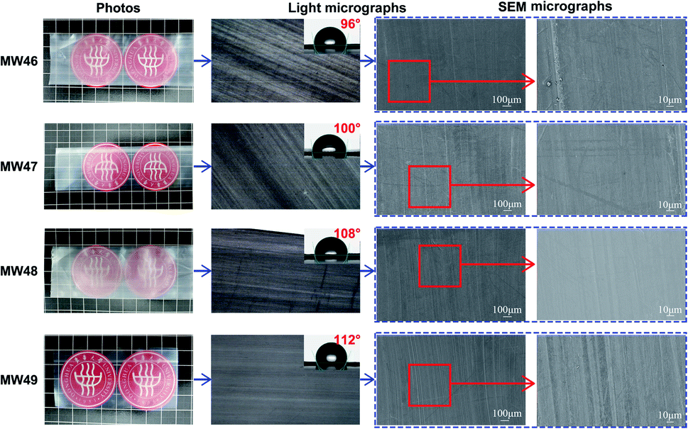 | ||
| Fig. 2 Photos, light, water contact angle, and SEM micrographs of the PTFE sintered films with different molecular weights. | ||
 | ||
| Fig. 3 Transmittance of visible light spectra of the PTFE sintered films with different molecular weights. | ||
Based on light transmittances and light micrographs of the PTFE sintered films, it could be inferred that the degree of the uniform arrangement of the PTFE molecular chains in the MW49 sintered film is the highest, while it is the lowest in the MW46 sintered film.
According to the light micrographs in Fig. 2, the smoothness and water contact angle of the PTFE sintered films significantly increase with the molecular weight. As discussed in the previous paper,17 the water contact angle of the PTFE polymer ranges from 110° to 120°, indicating that the MW49 sintered film has the smoothest surface.
Fig. 2 shows the morphology of the four different PTFE sintered films. The corresponding SEM micrographs indicate some microscale grooves and powder agglomerates attached to the surface of the MW46 sintered film. The number of grooves rapidly decreases, and the powder agglomerates do not appear on the PTFE sintered films when the molecular weight increases. These results show the highest smoothness of the MW49 sintered film, which is consistent with the light microscopy results of the PTFE sintered films.
3.2 Waterjet impacting of the PTFE sintered films
Fig. 4–7 illustrate the morphology of the PTFE sintered films impacted by waterjets with different pressures. The PTFE sintered films are split by waterjet impacting. | ||
| Fig. 4 Light micrographs of the MW46 PTFE sintered films split by waterjets with different pressures and manifolds; the blue scale bar is equal to 400 μm. | ||
 | ||
| Fig. 5 Light micrographs of MW47 PTFE sintered films split by waterjets with different pressures and manifolds; the blue scale bar is equal to 400 μm. | ||
 | ||
| Fig. 6 Light micrographs of the MW48 PTFE sintered films split by waterjets with different pressures and manifolds; the blue scale bar is equal to 400 μm. | ||
 | ||
| Fig. 7 Light micrographs of the MW49 PTFE sintered films split by waterjets with different pressures and manifolds; the blue scale bar is equal to 400 μm. | ||
Keeping in mind the results shown in Fig. 2, where the original PTFE sintered films are macroscopically continuous and without cracks, the formation of cracks and fibrils on the waterjet-impacted PTFE sintered films is attributed to the action of waterjets.
As shown in Fig. 4 and 5, bright oval spots appear on the MW46 and MW47 sintered films after waterjet impacting. At 80 bar, the waterjet-impacted PTFE sintered films do not show significant spots. The brightness of oval spots in the MW46 and MW47 sintered films significantly increases with the waterjet pressure. These elliptical spots were formed when water impacted the sintered film, increasing the light transmittance and decreasing the difficulty of splitting the PTFE sintered films. When the waterjet pressure is 110 bar, the center of spots in MW46 and MW47 sintered films is transparent, and some microscale fibers that originate from the edge and surface of the films attach to the sintered films. The water contact angles of the PTFE sintered films are higher than 90°, implying that the waterjet energy is completely used to impact the PTFE sintered films. The formed bright oval spots on the MW46 and MW47 sintered films are beneficial for distributing the waterjet impact stress. When waterjets impact the PTFE sintered films, the PTFE molecular chains absorb their kinetic energy. The impacted molecular chains move largely along the gradient direction of the waterjet impact stress attenuation. The density of the arranged PTFE molecular chains decreases in the central area of the impacted PTFE sintered films since their number is lower, enhancing the transparency of the oval spots in the sintered films. These findings suggest that waterjet impacting changed the arrangement of the PTFE molecular chains and split sintered films into the microscale fibers.
Fig. 6 and 7 show the MW48 and MW49 sintered films after waterjet impacting. There are no bright oval spots in the sintered films, implying that the waterjet energy does not significantly affect the arrangement of PTFE molecular chains in the sintered films. This behavior is attributed to the length and entanglement of the PTFE molecular chains. Compared with the MW46 and MW47 sintered films, the MW48 and MW49 sintered films possess a higher length and stronger entanglement of the PTFE molecular chains. When longer molecular chains absorb the waterjet kinetic energy, they move only slightly, showing little effect on the arrangement of the PTFE molecular chains, which explains the absence of bright oval spots in the MW48 and MW49 sintered films after waterjet impacting. According to Fig. 6 and 7, the increase in the number of jets enhances the splitting effect of sintered films and increases the number of microscale fibers. A few small cracks appear on the MW48 and MW49 sintered films impacted by one jet with a pressure of 80 bar. When the number of jets is more than 3, there are many microscale fibers on the surface of the PTFE sintered films. When the pressure reaches 110 bar, the PTFE sintered films impacted by one jet show many cracks and microscale fibers. MW48 and MW49 sintered films impacted by five jets under 110 bar are highly split, exhibiting many microscale fibers. A further pressure increase does not enhance the splitting degree and the number of microscale fibers significantly.
Fig. 8–11 show the morphology of the waterjet-impacted PTFE sintered films. Although waterjet impacting has changed the arrangements of the PTFE molecular chains of the MW46 and MW47 sintered films, it does not considerably influence their microscale morphology, as shown in Fig. 8 and 9. Small cracks form in the MW46, MW47, and MW48 sintered films impacted by one jet at 80 bar (Fig. 8–10) but there are no microscale PTFE fibers. The sintered films were split into microscale fibers with a diameter lower than 10 μm by increasing the number of jets.
 | ||
| Fig. 8 Morphology of the MW46 PTFE sintered films split by waterjets at different pressures and number of jets; the scale bar is equal to 100 μm. | ||
 | ||
| Fig. 9 Morphology of the MW47 PTFE sintered films split by waterjets at different pressures and number of jets; the scale bar is equal to 100 μm. | ||
 | ||
| Fig. 10 Morphology of the MW48 PTFE sintered films split by waterjets at different pressures and number of jets; the scale bar is equal to 100 μm. | ||
 | ||
| Fig. 11 Morphology of the MW49 PTFE sintered films split by waterjets at different pressures and number of jets; the scale bar is equal to 100 μm. | ||
According to the existing literature, waterjet impacting erosion assumes the interaction between the gradient impact stress and the target.18,19 As for the PTFE polymer, the effect of waterjet impacting on the sintered films is strongly correlated to the stable state of the PTFE molecular chain arrangement. The characteristics of molecular chain arrangements of the four PTFE sintered films with different molecular weights are inferred from the XRD patterns shown in Fig. 12. The crystallinity values of the MW46, MW47, MW48, and MW49 PTFE sintered films are 71.4, 67.8, 63.6, and 62.1%, respectively. In the crystalline area, the PTFE molecular chains are in a stable state. When waterjets impact the sintered film, the PTFE molecular chains in the amorphous area absorb the kinetic energy and change their position. These molecular chains collide with adjacent molecular chains and transfer the energy, yielding microscale cracks in the sintered films. These molecular chains change their positions and have larger displacements by increasing the number of jets. Suppose that the displacement between the PTFE molecular chains reaches a critical interval. In such a case, the impacted molecular chains cannot transfer the kinetic energy to adjacent chains to separate them from the sintered films and form microscale fibers. Therefore, the splitting of the impacted MW46, MW47, and MW48 sintered films into microscale fibers is significantly enhanced with the waterjet pressure.
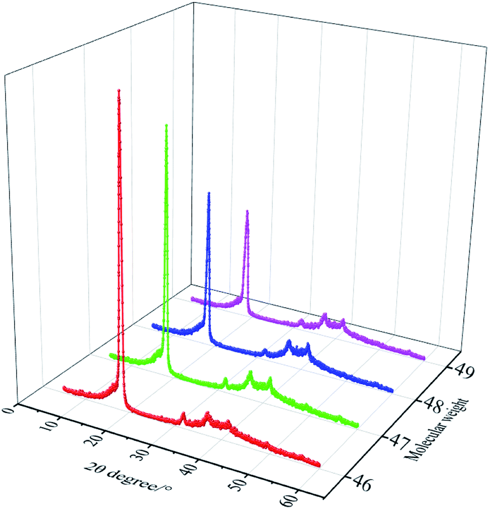 | ||
| Fig. 12 XRD patterns of the four PTFE sintered films with different molecular weights. | ||
As shown in Fig. 11, the MW49 sintered film impacted by one jet at 80 bar exhibits small cracks and a few microscale fibers. Compared with the MW46, MW47, and MW48 sintered films, long PTFE molecular chains in the MW49 sintered film are orientated along the stretching force direction during hot stretching. When the sintered film cooled down from a high temperature to the ambient temperature, longer molecular chains move less than the shorter molecular chains. Hence, there are fewer PTFE molecular chains in the crystalline area of the MW49 sintered film than in the MW46, MW47, and MW 48 sintered films. The MW49 sintered film splits more readily into microscale fibers than the other three sintered films due to weak interaction between the PTFE molecular chains.
According to Fig. 8–11, the PTFE sintered films impacted by three jets show significant splitting. PTFE sintered films impacted by five jets at 110 bar show extensive splitting into many microscale fibers, while any further waterjet pressure increase does not induce significant changes.
3.3 Waterjet impacting of the PTFE fibers
 | ||
| Fig. 13 Morphologies and fiber diameter distributions of the original PTFE split-film fibers with different molecular weights; the scale bar is equal to 100 μm. | ||
The average diameter of four different (namely, MW46, MW47, MW48, and MW49) PTFE split-film fibers is 25.3, 30.0, 38.9, and 27.4 μm, respectively, which is associated with the arrangement of the PTFE molecular chains in the sintered films.
The PTFE molecular chains in the MW46 sintered film separate from each other much easier than in other sintered films, yielding the formation of a lower average diameter of the split-film fibers. During cooling to ambient temperature, the molecular chains in the PTFE sintered film entangle with the adjacent molecular chains, yielding a decreased splitting performance of the sintered films and an increased average diameter of the split-film fibers. Longer molecular chains lead to weaker splitting performance of the PTFE sintered films. Hence, the average diameter of the MW48 split-film fibers reaches 38.9 μm. When the PTFE molecular chain length further increases, their kinetic energy is insufficient to significantly affect the chain displacement, yielding a decrease in the entanglement of the PTFE molecular chains and an increase in the splitting performance of the sintered films. Therefore, the average diameter of the MW49 split-film fibers decreases to 27.4 μm.
Fig. 13 also shows that the relative contents of fibers with different diameter distributions change with the molecular weight. The content of fibers with a diameter from 1 to 16 μm firstly decreases and then increases with the molecular weight, while the content of the fibers with a diameter ranging from 16 to 32 μm does not show any significant trend. The content of fibers with a diameter from 32 to 48 μm initially increases and then decreases. In summary, with a molecular weight increase, the average diameter of the PTFE split-film fibers initially exhibits an increase and then a decrease. Also, the content of the fibers with a diameter from 1 to 32 μm has a decisive effect on the average diameter of the PTFE split-film fibers.
 | ||
| Fig. 14 SEM micrographs of the MW46 PTFE fibers impacted by waterjets at different pressures and number of jets; the scale bar is equal to 100 μm. | ||
 | ||
| Fig. 15 SEM micrographs of the MW47 PTFE fibers impacted by waterjets at different pressures and number of jets; the scale bar is equal to 100 μm. | ||
 | ||
| Fig. 16 SEM micrographs of the MW48 PTFE fibers impacted by waterjets at different pressures and number of jets; the scale bar is equal to 100 μm. | ||
 | ||
| Fig. 17 SEM micrographs of the MW49 PTFE fibers impacted by waterjets at different pressures and number of jets; the scale bar is equal to 100 μm. | ||
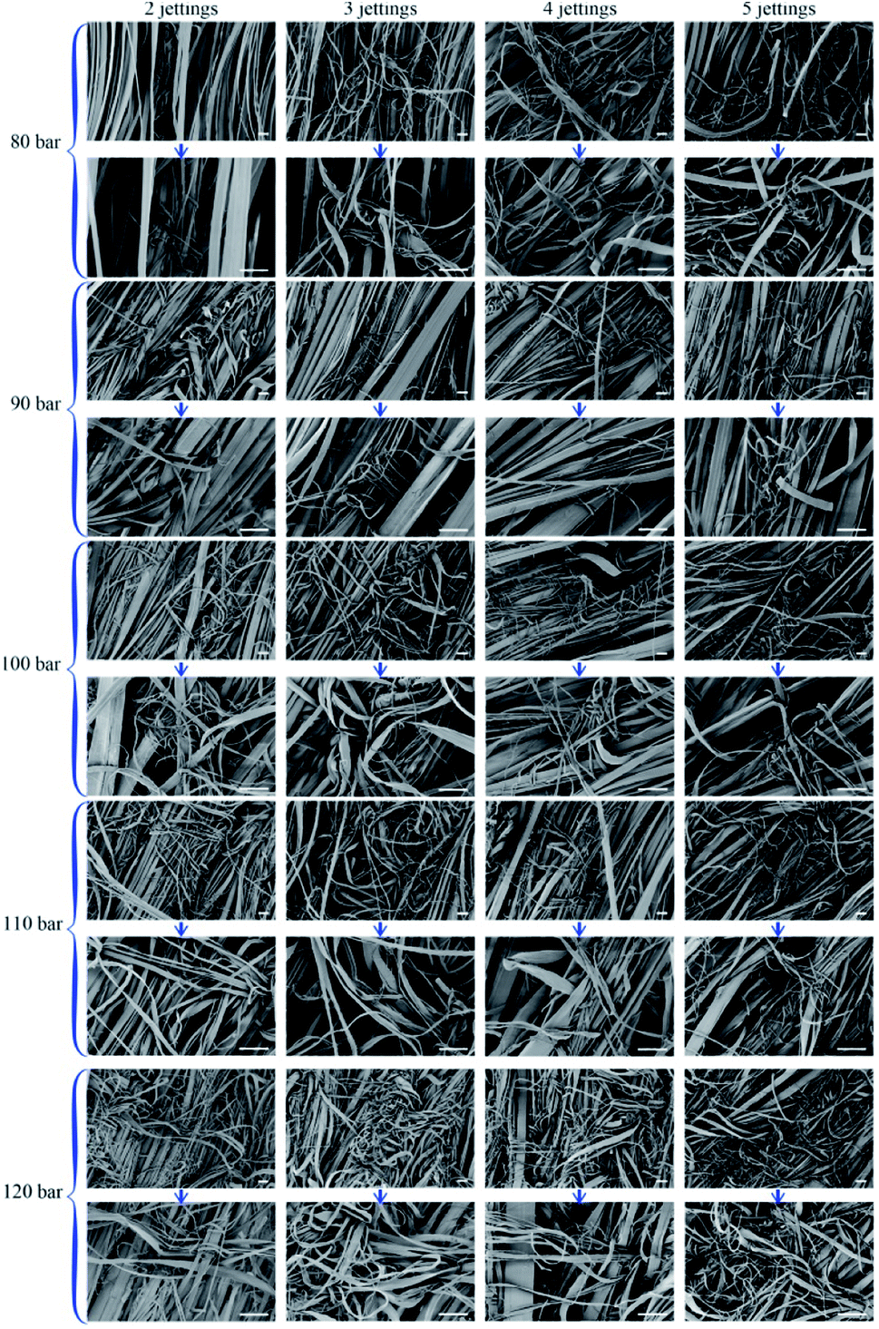
At 100 bar, most of the MW46 and MW47 split-film fibers impacted by five jets are split into microscale fibers. A further pressure increase does not significantly change the number of microscale fibers in impacted MW46 and MW47 split-film fibers. Nevertheless, the size of the clump composed of entangled fibers further increases. In the cases of MW48 and MW49 split-film fibers impacted by five jets at 100 bar, many fibers have a large diameter, although a large quantity of the fibers is split into microscale fibers. By increasing the pressure to 110 bar, most of the MW48 and MW49 split-film fibers are split into microscale fibers under the same other processing conditions. When the pressure further increases, i.e., in the impacting force of waterjets, it yields entanglements of the microscale fibers (as displayed in Fig. 16 and 17).
As described in our previous literature,8 although the PTFE filament manufactured by the extrusion or slitting process showed a smooth morphology, the average diameter of the PTFE round or flat filaments was more than 100 μm, much higher than that of the PTFE split-film fibers. In the electrospinning process,9 a filter mat composed of highly-entangled nanoscale PTFE nanoscale fibers (∼500 nm) was prepared. These PTFE ultrafine fibers were not stretched, and the molecular chains in the fibers were not oriented, yielding poor mechanical properties. A clump consisting of intertwined PTFE nanofibers was prepared by the jet blowing method.10 However, this method could not be used to fabricate PTFE fine fibers operated in the carding machine.
Hence, fine fibers were obtained for the MW46 and MW47 split-film fibers at 100 bar, while for the MW48 and MW49 split-film fibers, it occurs at 110 bar for impacting by five jets. These results are consistent with the conclusions drawn from the morphology of the sintered films (Fig. 4–8).
The variations in the average diameter of the PTFE fibers impacted by waterjets at different pressures and number of jets are shown in Fig. 18. The average diameter of the PTFE fibers significantly decreases with the pressure and the number of jets. Nevertheless, once the average diameter of PTFE fibers decreases to a critical value, it does not significantly change further (the purple area in Fig. 18).
 | ||
| Fig. 18 The average diameter variation of different PTFE split-film fibers with the pressure and number of jets. | ||
The projection of the average diameter variation with the pressure and number of jets shows that the average diameter of the MW46 or MW47 fibers impacted by five jets reaches the purple area at 100 bar, while for the MW48 or MW49 fibers, it occurs at 110 bar, which is consistent with the results shown in Fig. 14–17.
The decrease (%) in the average diameter of the PTFE split-film fibers impacted by waterjets is listed in Table 1. At 100 bar, the average diameter of the MW46 and MW47 split-film fibers impacted by five jets decreases by 37.55 and 39.67%, respectively, while it does not change significantly for the MW46 and MW47 split-film fibers. At 110 bar, the average diameter of the MW48 and MW49 split-film fibers impacted by the five jets decreases by 47.04 and 42.7%, respectively. The average diameter of the MW46 and MW47 split-film fibers impacted by five jets at 100 bar decreases from 25.3 to 15.8 μm and from 30.0 to 18.1 μm, respectively. For the MW48 and MW49 split-film fibers impacted by five jets at 110 bar, the average diameter decreases from 38.9 to 20.6 μm and from 27.4 to 15.7 μm, respectively. Finally, the MW48 and MW49 split-film fibers exhibit better waterjet splitting performance, reducing the average diameter by more than 40%, or even 45%, respectively.
| Pressure/bar | Jets | MW46 | MW47 | MW48 | MW49 | ||||
|---|---|---|---|---|---|---|---|---|---|
| Width/μm | Decrease/% | Width/μm | Decrease/% | Width/μm | Decrease/% | Width/μm | Decrease/% | ||
| 80 | 2 | 23.2 | 8.30 | 28.9 | 3.67 | 31.1 | 20.05 | 24.6 | 10.22 |
| 3 | 22.8 | 9.88 | 27.7 | 7.67 | 30.4 | 21.85 | 24.2 | 11.68 | |
| 4 | 22.2 | 12.25 | 26.8 | 10.67 | 30.2 | 22.37 | 22.8 | 16.79 | |
| 5 | 21.0 | 17.00 | 24.5 | 18.33 | 26.9 | 30.85 | 21.8 | 20.44 | |
| 90 | 2 | 22.6 | 10.67 | 24.7 | 17.67 | 30.6 | 21.34 | 23.1 | 15.69 |
| 3 | 22.1 | 12.65 | 22.6 | 24.67 | 29.7 | 23.65 | 22.1 | 19.34 | |
| 4 | 19.8 | 21.74 | 21.3 | 29.00 | 28.5 | 26.74 | 21.3 | 22.26 | |
| 5 | 18.7 | 26.09 | 20.5 | 31.67 | 25.3 | 34.96 | 20.4 | 25.55 | |
| 100 | 2 | 20.4 | 19.37 | 24.4 | 18.67 | 29.4 | 24.42 | 22.3 | 18.61 |
| 3 | 19.7 | 22.13 | 20.9 | 30.33 | 27.4 | 29.56 | 21.4 | 21.90 | |
| 4 | 17.9 | 29.25 | 18.8 | 37.33 | 24.8 | 36.25 | 20.6 | 24.82 | |
| 5 | 15.8 | 37.55 | 18.1 | 39.67 | 21.9 | 43.70 | 19.6 | 28.47 | |
| 110 | 2 | 19.7 | 22.13 | 21.4 | 28.67 | 26.1 | 32.90 | 20.7 | 24.45 |
| 3 | 18.1 | 28.46 | 20.5 | 31.67 | 22.9 | 41.13 | 18.5 | 32.48 | |
| 4 | 16.9 | 33.20 | 19.1 | 36.33 | 21.2 | 45.50 | 16.5 | 39.78 | |
| 5 | 15.9 | 37.15 | 18.7 | 37.67 | 20.6 | 47.04 | 15.7 | 42.70 | |
| 120 | 2 | 18.5 | 26.88 | 21.3 | 29.00 | 24.4 | 37.28 | 20.3 | 25.91 |
| 3 | 17.3 | 31.62 | 19.9 | 33.67 | 23.1 | 40.62 | 18.2 | 33.58 | |
| 4 | 16.6 | 34.39 | 18.6 | 38.00 | 20.7 | 46.79 | 16.1 | 41.24 | |
| 5 | 16.0 | 36.76 | 18.0 | 40.00 | 20.1 | 48.33 | 15.3 | 44.16 | |
4. Conclusions
In this study, the waterjet impacting technology was introduced to separate the PTFE split-film fibers into fine fibers, enabling the highly-efficient manufacturing of the microscale PTFE fibers. With an increase in the molecular weight, the visible light transmittance of the PTFE sintered film showed a slight decrease from 85.7 to 77.6%, and then an increase to 95.1%, which was consistent with the light–dark strip characteristic of the sintered films. In addition, according to the water contact angle (90°), the PTFE sintered film showed excellent hydrophobic performance. Furthermore, different numbers of jets at different pressures were adapted to impact the PTFE sintered films and analyze the splitting effect. Four PTFE sintered films were split into microscale fibers by waterjet impacting at 110 bar and 5 jets. At the same pressure and the number of jets, the MW49 sintered film showed the most significant splitting effect, which is attributed to its low crystallinity (62.1%). The average diameter of the PTFE split-film fibers with different molecular weights impacted by waterjets at different pressures and the number of jets was studied. In original PTFE split-film fibers, the content of fibers with a low diameter (<32 μm) was less than 80%. After waterjet impacting, this content in the four PTFE split-film fibers showed a significant increase (>90%), leading to a drastic decrease in the average diameter. In particular, the average diameter of MW49 PTFE split-film fibers impacted by five jets at 110 bar decreased from 27.4 to 15.7 μm, i.e., more than 40%. Hence, the waterjet impacting technology can be used to separate the original PTFE split-film fibers into fine fibers and manufacture microscale PTFE fibers with high efficiency.Author contributions
Conceptualization, Yukang Xu and Xiangyu Jin; methodology, Yukang Xu and Xiangyu Jin; validation, Yukang Xu and Xiangyu Jin; formal analysis, Yukang Xu, Lei Wang and Guangliang Tian; writing—original draft preparation, Yukang Xu; writing—review and editing, Yuanyuan Li, Ping Wang, and Zhijuan Pan; supervision, Xiangyu Jin; project administration, Yukang Xu; funding acquisition, Yukang Xu. All authors have read and agreed to the published version of the manuscript.Conflicts of interest
There are no conflicts to declare.Acknowledgements
This study was supported the by National Natural Science Foundation of China (No. 51903183) and the Doctoral Fund of Ministry of Education of China (No. 2020M671577). Besides, the authors appreciate the great help received from Linflon New-Materials Technology Jiangsu Co., Ltd (China).Notes and references
- M. Lupión, F. J. G. Ortiz, B. Navarrete and V. J. Cortés, Fuel, 2010, 89, 848–854 CrossRef.
- D. Jiang, W. Zhang, J. Liu, W. Geng and Z. Ren, Korean J. Chem. Eng., 2008, 25, 744–753 CrossRef CAS.
- S. Kreiser, Filtr. Sep., 2013, 50, 36–37 CrossRef.
- A. Wimmer, Filtr. Sep., 1999, 2, 26–28 Search PubMed.
- Y. Wang, Y. Xu, D. Wang, Y. Zhang, X. Zhang, J. Liu, Y. Zhao, C. Huang and X. Jin, ACS Appl. Mater. Interfaces, 2019, 11, 48437–48449 CrossRef CAS PubMed.
- M. I. F. Rozy, M. Ueda, T. Fukasawa, T. Ishigami and K. Fukui, AIChE J., 2020, 66, e16832 CrossRef CAS.
- J. S. Kim and M.-H. Lee, Powder Technol., 2019, 343, 662–670 CrossRef CAS.
- Y. Xu, C. Huang and X. Jin, J. Appl. Polym. Sci., 2016, 133(26), 43553 Search PubMed.
- S. J. Zhu, Y. Y. Zhou, O. Takashi and G. Wu, Mater. Sci. Forum, 2011, 675–677, 827–830 CAS.
- S. Borkar, B. Gu, M. Dirmyer, R. Delicado, A. Sen, B. R. Jackson and J. V. Badding, Polymer, 2006, 47, 8337–8343 CrossRef CAS.
- Y. Xue, H. Si, D. Xu and Z. Yang, Powder Technol., 2018, 332, 139–149 CrossRef CAS.
- H. Soyama, Y. Yanauchi, K. Sato, T. Ikohagi, R. Oba and R. Oshima, Exp. Therm. Fluid Sci., 1996, 12, 411–416 CrossRef.
- F. Chen, X. Miao, Y. Tang and S. Yin, Int. J. Adv. Manuf. Technol., 2017, 90, 785–799 CrossRef.
- C. Narayanan, R. Balz, D. A. Weiss and K. C. Heiniger, J. Mater. Process. Technol., 2013, 213, 2201–2210 CrossRef.
- Y. Zhang, C. Deng, Y. Wang, C. Huang, Y. Zhao and X. Jin, J. Ind. Text., 2019, 48, 1136–1150 CrossRef.
- S. Gulhane, R. Turukmane, C. Mahajan and M. Joshi, Chem. Fibers Int., 2018, 4, 190–192 Search PubMed.
- J. Zhang, J. Li and Y. Han, Macromol. Rapid Commun., 2004, 25, 1105–1108 CrossRef CAS.
- K. Maniadaki, T. Kestis, N. Bilalis and A. Antoniadis, Int. J. Adv. Manuf. Technol., 2007, 31, 933–940 CrossRef.
- T. Mabrouki, K. Raissi and A. Cornier, Wear, 2000, 239, 260–273 CrossRef CAS.
Footnote |
| † Electronic supplementary information (ESI) available. See DOI: 10.1039/d1ra05074e |
| This journal is © The Royal Society of Chemistry 2021 |