DOI:
10.1039/D1RA03737D
(Paper)
RSC Adv., 2021,
11, 23975-23984
Highly sensitive detection of nitrobenzene by a series of fluorescent 2D zinc(II) metal–organic frameworks with a flexible triangular ligand†
Received
13th May 2021
, Accepted 15th June 2021
First published on 7th July 2021
Abstract
Four fluorescent zinc(II) metal–organic frameworks, namely [Zn(HCIA)(4,4′-bipy)] (1), [Zn2(CIA)(OH)(1,4-bibz)1.5]·H2O (2), [Zn(CIA)(OH) (4,4′-bbpy)] (3), and [Zn2(HCIA) (4,4′-bimp)]·H2O (4), were prepared hydrothermally with a flexible triangular ligand (H3CIA) and a series of linear N-donor ligands (H3CIA = 5-(2-carboxybenzyloxy) isophthalic acid, 4,4′-bipy = 4,4′-bipydine, 1,4-bibz = 1,4-bis(1-imidazoly)benzene; 4,4′-bbpy = 4,4′-bis (imidazolyl) biphenyl; 4,4′-bimp = 4,4′-bis (imidazole-1-ylethyl) biphenyl). Structural analyses revealed that complex 1 exhibited a 2D brick-like network structure based on the basic bimetallic ring, 2 was also a 2D interspersed structure from the 1D tubular structure, compound 3 possessed a 2D (4,4) network with 4,4′-bbpy occupying the holes, and complex 4 displayed a 2D network from the 1D ladder-like chain. The thermal stabilities and fluorescent properties of these complexes were investigated in the solid state. The fluorescent sensing experiments revealed that all Zn-MOFs could highly sensitively detect nitrobenzene in aqueous solution, which indicated that these materials can be used as fluorescent probes for the detection of nitrobenzene.
Introduction
Metal–organic frameworks (MOFs) have seen much rapid development in recent years, with interest derived from their structural variability and many functional applications including fluorescence sensors,1 magnetism,2 gas adsorption and exchange,3 and heterogeneous catalysis.4 As fluorescence materials, luminescence MOFs have been employed to detect metal ions,5 anions,6 organic solvents,7 antibiotics,8 pollutants,9 pesticides,10 and some small molecules11 with a high selectivity and sensitivity because of their advantages of adjustable pore sizes and variable functional groups. Fluorescence sensor investigations based on MOFs have mainly centered on lanthanide-MOFs (Ln = Eu3+ and Tb3+) and transition metal MOFs (Zn2+ and Cd2+) in recent years.12 Nitrobenzene (NB) is a widely used organic synthesis intermediate in the organic synthesis industry, but its high toxicity to humans has inspired the development of rapid detection methods and experiments for it. Various detection methods for NB have been developed, such as gas chromatography, high-performance liquid chromatography (HPLC), and electrochemical analysis.13 However compared with these analysis methods, fluorescent probes based on MOFs being developed to detect NB are showing increasing advantages including structural design ability, pore size tenability, host–guest interaction, and stable luminescence. A large number of fluorescent Ln-MOF probes for the detection of nitrobenzene have been discovered, and several Zn/Cd-MOF probes have been used to detect nitrobenzene.14
Zn-MOFs are a class of rapidly developing MOF materials thanks to the simple and controllable coordination conditions of the zinc(II) ion, stable and microporous frameworks, and excellent fluorescence properties.15 Rigid or flexible organic ligands containing carboxyl groups are frequently used in the formation of Zn-MOFs, especially multi-carboxylate ligands such as 5-(2-carboxybenzyloxy) isophthalic acid (H3CIA), a flexible tri-carboxylate ligand with three carboxyl groups, which are more favorable for the coordination behavior with metal ions. Only a dozen MOFs based on the H3CIA ligand with Ni2+, Cd2+, Ln3+, and Zn2+ ions have been reported and these have exhibited diverse forms, structures, and properties.16 Based on the above research background, we tried to design a series of zinc-MOFs with the H3CIA ligand and four long-chain N-donor ligands (Chart 1), which we obtained as single crystals, and then used these to investigate their structural features and sensing properties toward nitrobenzene in aqueous solution.
 |
| | Chart 1 Structural representation of the ligands used in complexes 1–4. | |
Experimental
Materials and measurements
All the solvents and reagents were commercially available. Thermogravimetric analysis was performed using a NETZSCH STA 449C microanalyzer heated from 30 °C to 900 °C in an air atmosphere. The fluorescence spectra were determined by F-7100 fluorescence spectrophotometer at room temperature. Element analysis of the C, N, H, and O elements was performed using a Flash 2000 organic element analyzer. Powder X-ray diffraction (PXRD) patterns were obtained using a Rigaku Ultima IV diffractometer. The characteristic absorption peak of the MOFs was obtained by comparing the infrared spectrum with the standard infrared spectrum. The theoretical calculation was performed by Density Functional Theory (DFT).
Synthesis
[Zn(HCIA)(4,4′-bipy)] (1). ZnSO4·7H2O (0.029 g), H3CIA (0.016 g), and 4,4′-bipy (0.015 g) were mixed with 3 mL water and 0.3 mL NaOH (0.065 mol L−1) in a 25 mL Teflon-lined stainless steel container and heated at 160 °C for 72 h. The final mixture was sealed in a 15 mL Teflon-lined autoclave and heated under autogenous pressure to 160 °C for 72 h and then allowed to cool to room temperature naturally. After filtration, some saffron yellow schistose crystals were collected, washed with water, and then air dried (yield 63% based on Zn). Anal. calcd for C26H18N2O7Zn (1): C, 58.27%; H, 3.38%; N, 5.23%. Found: C, 58.59%; H, 2.99%; N, 5.37%. IR (KBr, cm−1): 3084 (m), 3067 (w), 1661 (s), 1604 (s), 1559 (m), 1508 (m), 1479 (m), 1474 (m).
[Zn2(CIA)(OH)(1,4-bibz)1.5]·H2O (2). ZnSO4·7H2O (0.029 g), 2-H3CIA (0.016 g), and 1,4-bibz (0.015 g) were mixed with 3 mL buffer solvent (pH = 6) in a 25 mL Teflon-lined stainless steel container. The final mixture was sealed in a 15 mL Teflon-lined autoclave and heated under autogenous pressure to 160 °C for 72 h and then allowed to cool to room temperature naturally. After filtration, some yellow block crystals were collected, washed with water, and then air dried (yield 58% based on Zn). Anal. calcd for C34H26N6O8.5Zn2 (2): C, 51.99%; H, 3.34%; N, 10.70%. Found: C, 52.15%; H, 3.03%; N, 10.52%. IR (KBr, cm−1): 3129 (m), 1622 (s), 1593 (s), 1570 (m), 1542 (s), 1530 (m), 1463 (s), 1417 (m).
[Zn2(CIA)(OH)(4,4′-bbpy)] (3). ZnSO4·7H2O (0.029 g), H3CIA (0.016 g), and 4,4′-bbpy (0.015 g) were mixed with 3 mL buffer solvent (pH = 6) and 1 mL methyl alcohol in a 25 mL Teflon-lined stainless steel container. The final mixture was sealed in a 15 mL Teflon-lined autoclave and heated under autogenous pressure to 160 °C for 72 h and then allowed to cool to room temperature naturally. After filtration, some yellow block crystals were collected, washed with water, and then air dried (yield 46% based on Zn). Anal. calcd for C34H24N4O8Zn2 (3): C, 54.64%; H, 3.24%; N, 7.50%. Found: C, 54.42%; H, 3.31%; N, 7.73%. IR(KBr, cm−1): 3129 (m), 3090 (w), 1570 (s), 1536 (m), 1519 (s), 1468 (s), 1417 (m).
[Zn(HCIA)(4,4′-bimp)]·H2O (4). ZnSO4·7H2O (0.029 g),H3CIA (0.016 g), and 4,4′-bimp (0.015 g) were mixed with 3 mL water, 0.3 mL NaOH (0.065 mol L−1) and 1 mL isopropanol in a 25 mL Teflon-lined stainless steel container. The final mixture was sealed in a 15 mL Teflon-lined autoclave and heated under autogenous pressure to 160 °C for 72 h and then allowed to cool to room temperature naturally. After filtration, some brown block crystals were collected, washed with water, and then air dried (yield 46% based on Zn). Anal. calcd for C36H30N4O8Zn (4): C, 60.72%; H, 4.25%; N, 7.87%. Found: C, 60.54%; H, 34.66%; N, 7.68%. IR (KBr, cm−1): 3129 (m), 3072 (w), 1622 (s), 1553 (s), 1525 (m), 1474 (s), 1434 (w), 1423 (w).
Crystal structure determination
Single-crystal X-ray diffraction analyses of the four complexes were carried out on a Bruker SMART APEX CCD diffractometer equipped with graphite monochromated Mo-Kα radiation (λ = 0.71073 Å). Raw data were integrated with the SAINT program.17 The structures were solved by direct methods with SHELXS-97 and refined by full-matrix least-squares on F2 using SHELXS-97.18 An empirical absorption correction was applied with the program SADABS.19 All the non-hydrogen atoms were refined anisotropically. The hydrogen atoms were set in the calculated positions and refined by a riding mode. The crystallographic details of complexes 1–4 are provided in Table 1, while the selected bond distances and angles are listed in Tables S1–S4.†
Table 1 Crystallographic data for complexes 1–4
| Complex |
1 |
2 |
3 |
4 |
| Empirical formula |
C26H18N2O7Zn |
C34H26N6O8.5Zn2 |
C34H24N4O8Zn2 |
C36H30N4O8Zn |
| Formula weight |
535.79 |
785.35 |
747.31 |
712.01 |
| Space group |
P![[1 with combining macron]](https://www.rsc.org/images/entities/char_0031_0304.gif) |
P |
P2(1)/n |
P |
| a/Å |
7.4270(3) |
10.203(4) |
15.9212(16) |
9.764(3) |
| b/Å |
12.0551(5) |
11.768(5) |
11.5181(11) |
11.687(3) |
| c/Å |
13.0522(5) |
14.073(6) |
17.0439(17) |
15.345(4) |
| α/° |
82.5430(10) |
86.764(7) |
90 |
106.065(4) |
| β/° |
86.4380(10) |
80.749(6) |
105.5296(16) |
91.671(4) |
| γ/° |
77.6410(10) |
77.297(6) |
90 |
102.175(3) |
| V/Å3 |
1131.16(8) |
1626.5(11) |
3011.4(5) |
1637.7(7) |
| Z, calculated density |
2, 1.573 mg m−3 |
2, 1.604 mg m−3 |
4, 1.648 mg m−3 |
2, 1.444 mg m−3 |
| Absorption coefficient |
1.138 mm−1 |
1.540 mm−1 |
1.656 mm−1 |
0.810 mm−1 |
| F(000) |
548 |
800 |
1520 |
736 |
| Theta range for data collection |
2.982 to 27.509° |
2.714 to 28.569° |
2.481 to 28.298° |
2.442 to 28.316° |
| Reflections collected/unique |
23![[thin space (1/6-em)]](https://www.rsc.org/images/entities/char_2009.gif) 964/5201 964/5201 |
10394/7641 |
18485/7278 |
9856/7395 |
| GOF |
1.021 |
1.030 |
0.975 |
0.993 |
| Final R indices [I > 2 sigma(I)] |
R1 = 0.0440 |
R1 = 0.0336 |
R1 = 0.0380 |
R1 = 0.0556 |
| wR2 = 0.1053 |
wR2 = 0.0743 |
wR2 = 0.0945 |
wR2 = 0.1229 |
Sensing experiments
All the measurements were performed at room temperature. In order to improve the detection effect, the crystals were ground into a powder. The solid fluorescence of complexes 1–4 and ligands was determined. Overall, 18 different organic solvents: ethyl benzene (EB), formaldehyde (POM), n-pentane (NPE), 1,2-dichlorohydrin (DCE), isopropanol (IPA), ethanediol (EG), acetic ether (EAC), n-propyl alcohol (NPA), carbinol (MeOH), polyethylene glycol (PEG), benzene (PhH), N,N-dimethyl-formamide (DMF), cyclohexane (CYH), nitrobenzene (NB), acetonitrile (CH3CN), 1,2-propanediol (PG), n,n-dimethylacetamide (DMA), and methyl alcohol (MtOH), were used in the sensing experiments. First, 3 mg of the complex and 10 mL water were added to the glass bottle, and the Zn-MOF suspension was obtained after 1 h under ultrasonic treatment, and then left standing in air for 24 h. Then a stable suspension was formed, and the top liquid was utilized for fluorescence detection. To test the quenching properties of the complexes for nitrobenzene, 5 mL NB (5 mmol L−1) was added to 2 mL of the suspension of the complexes in turn. The excitation wavelengths of complexes 1–4 were 305, 269, 285, and 267 nm with the excitation/emission slit widths of 5, 2.5, 2.5, and 5 nm, respectively. For all the fluorescence experiments, the emission spectra were recorded in the range of 350–650 nm.
Results and discussions
Crystal structures
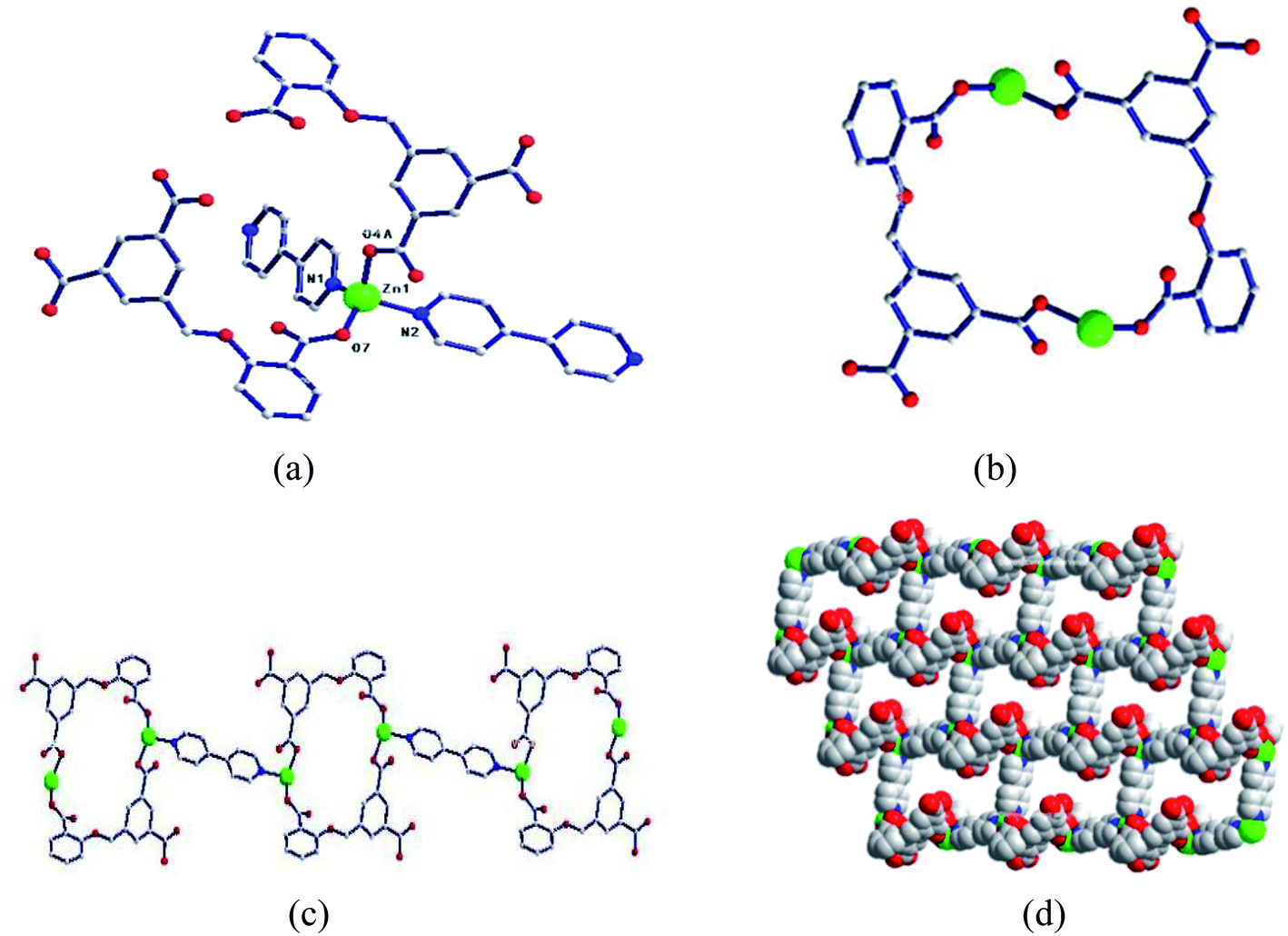
[Zn(HCIA)(4,4′-bipy)] (1). Single-crystal X-ray diffraction analysis showed that the central ion Zn1 was associated with two oxygen atoms (O4A, O7) of two HCIA2− ligands, and two nitrogen atoms of two 4,4′-bipyridines (N1, N2) coordinated to form a four-coordinate tetrahedral configuration (the symmetry code is (A) − x + 2, −y + 1, −z) (Fig. 1a). The bond length of Zn–O is 1.920–1.9470 Å and the bond length of Zn–N is 2.046–2.054 Å. The bond angle of N/O–Zn–O/N is 99.22–123.44°.
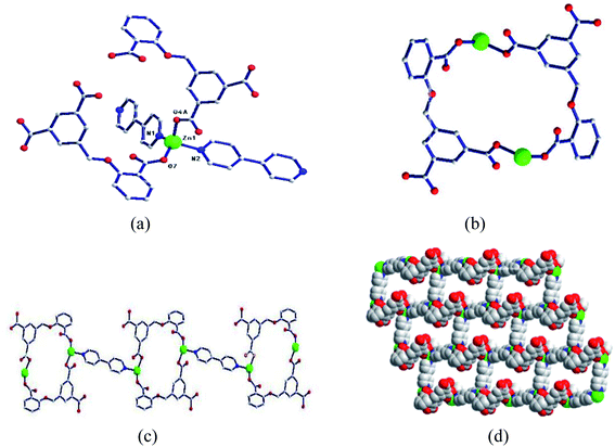 |
| | Fig. 1 (a) Coordination environment diagram of Zn ion in 1; (b) bimetallic ring; (c) one-dimensional chain based on a bimetallic unit ring; (d) two-dimensional network structure. | |
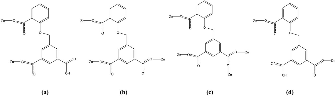
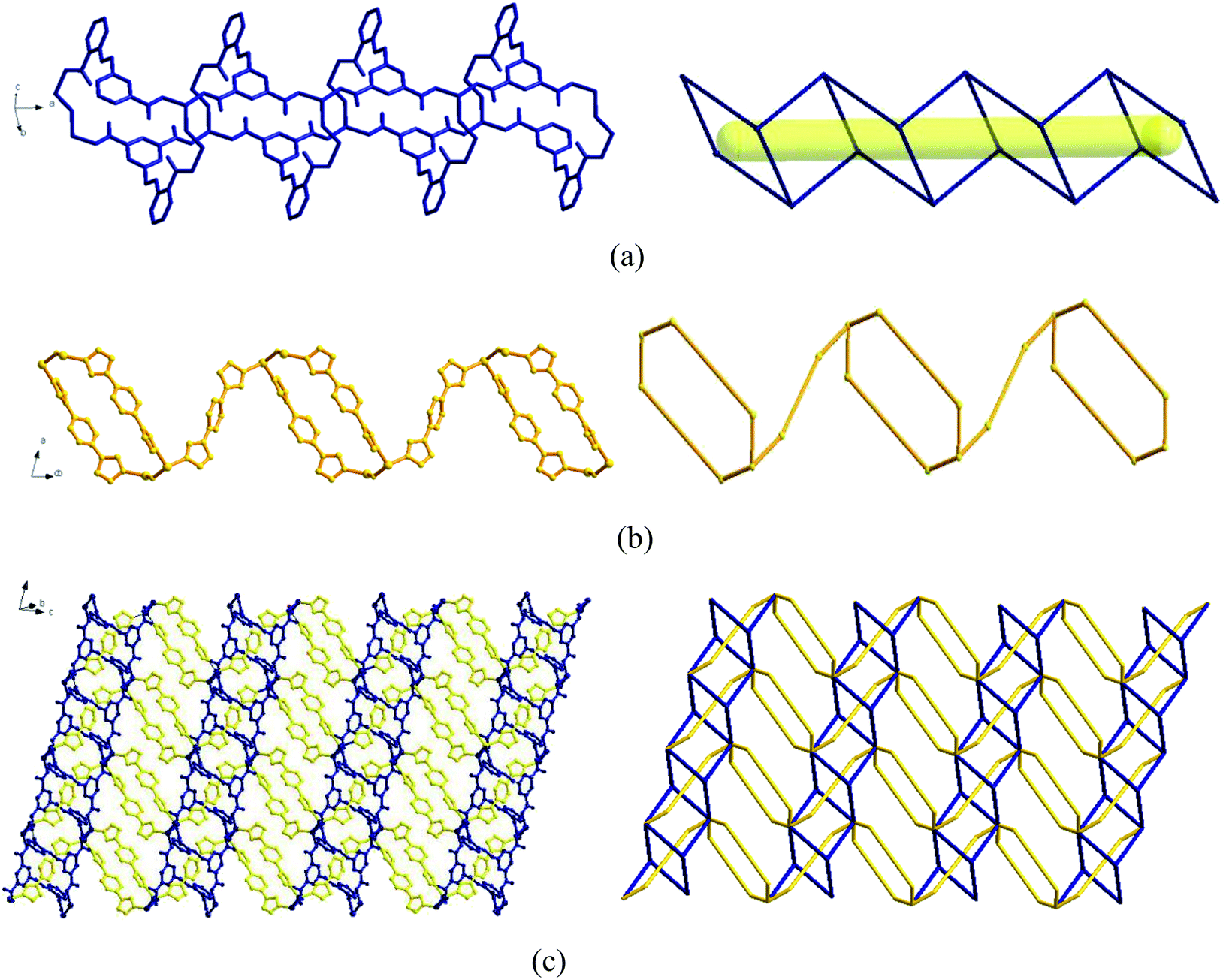
Two adjacent Zn ions form a bimetallic unit ring through two reverse bridges of HCIA2− in the κ1:κ1-μ2 mode (Chart 2a), and the adjacent bimetallic unit ring is bridged by 4,4′-bipy to form a one-dimensional (1D) chain structure (Fig. 1b and c), with adjacent 1D chains vertically connected by 4,4′-bipy to form a two-dimensional (2D) brick-like network structure (Fig. 1d).
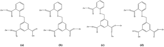 |
| | Chart 2 Coordination modes of the H3CIA ligands used in complexes 1–4. | |
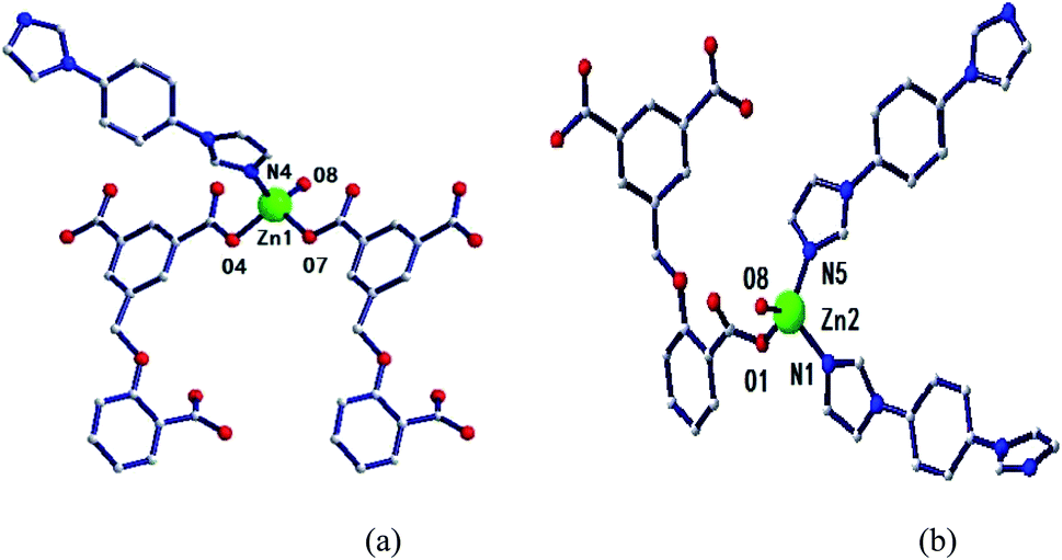
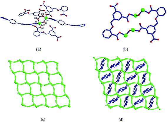
[Zn2(CIA)(OH)(1,4-bibz)1.5]·H2O (2). The complex was based on a 2D network structure in which two 1D chains are interspersed. Single-crystal X-ray diffraction analysis showed that there are two crystallographic independent metallic Zn ions in the complex. The Zn1 ion is coordinated with two carboxyl oxygen atoms (O4, O7) of CIA3− ligand, an oxygen atom (O8) of a hydroxyl group, and a nitrogen atom (N4) of an 1,4-bibz ligand to form a four-coordinated tetrahedral configuration (Fig. 2a) The central ion Zn2 is coordinated with a carboxyl oxygen atom (O1) of a CIA3− ligand, a hydroxyl oxygen atom (O8), and two nitrogen atoms (N1, N5) of two 1,4-bibz ligands. It also forms a four-coordinate tetrahedral configuration (Fig. 2b). The bond length range of Zn–O is 1.8848–2.005 Å, the bond length range of Zn–N is 2.000–2.0067 Å, the bond angle range of O–Zn–O is 104.64–115.54°, and the bond angles of O–Zn–N are in the range of 98.28–120.84°, and the bond angle of N–Zn–N is 110.05°.
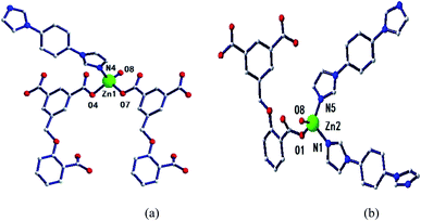 |
| | Fig. 2 Environmental coordination diagram of Zn1 (a) and Zn2 (b) ions in 2. | |
In the complex, Zn1 and Zn2 ions form a bimetallic unit through the bridging effect of hydroxyl μ2-O, and the metal polyhedrons are connected by a common point. The CIA3− ligand adopts the κ1:κ1:κ1-μ3 coordination mode (Chart 2b) to bridge the bimetallic unit to form a 1D tubular structure A (Fig. 3a), and the auxiliary ligand 1,4-bibz is connected to form a 1D wave chain structure B in a bidentate manner (Fig. 3b). Two types of 1D chains A and B are interspersed with each other, and are connected to form a 2D interspersed structure with bimetallic units as the nodes (Fig. 3c). The 2D interspersed structure is then stacked into a three-dimensional (3D) supramolecular structure through the π–π stacking force between the benzene ring of the CIA3− ligand and the 1,4-bibz ligand (distance from point to surface: 3.869 Å).
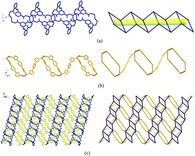 |
| | Fig. 3 (a) One-dimensional tubular structure formed by CIA3− and a bimetallic unit and its simplified diagram; (b) one-dimensional chain structure formed by 1,4-bibz and a bimetallic unit and its simplified diagram; (c) two-dimensional interspersed structure and its simplified diagram. | |
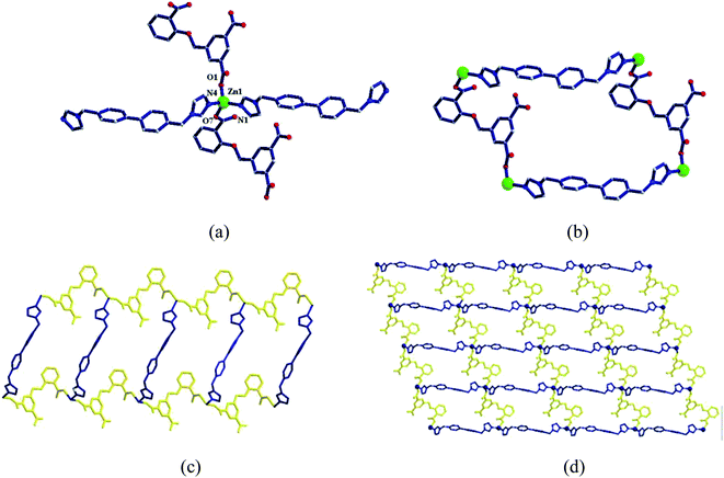
[Zn2(CIA)(OH)(4,4′-bbpy)] (3). Single-crystal X-ray diffraction analysis shows that the central atom Zn1 ion is associated with two oxygen atoms (O3, O1) of two CIA3− ligands, one nitrogen atom (N4) of an 4,4′-bbpy ligand, and a hydroxyl oxygen atom (O8). The central ion Zn2 ion is associated with two oxygen atoms (O4, O6) of the CIA3− ligand, one nitrogen atom (N1) of an 4,4′-bbpy ligand, and an oxygen atom of a hydroxyl molecule (O8), forming two opposite triangular cones (Fig. 4a). The bond length range of Zn–O is 1.925–2.024 Å, the bond length range of Zn–N is 2.004–2.024 Å, the bond angle range of O–Zn–O is 101.91–117.11°, and the bond angle range of O–Zn–N is 96.68–119.59°.
 |
| | Fig. 4 (a) Coordination environment diagram of Zn ion in 3, (b) four-metal unit rings, (c) two-dimensional (4,4) network, (d) two-dimensional network structure. | |
Two metal ions (Zn1, Zn2) are connected by the hydroxyl oxygen atom (O8) and two CIA3− ligands in the κ1:κ1:κ1:κ1-μ4 mode (Chart 2c) reversely to form a four-metal unit ring (Fig. 4b). The four-metal unit rings extend into a 1D chain by CIA3− ligands bridging (Fig. S1†). The 2D (4,4) network is constructed from the 1D chains based on CIA3− ligands (Fig. 4c). The nitrogen atoms of 4,4′-bbpy are coordinated to Zn2+ ions and occupy the back and forth positions in the metal unit rings and contribute to the formation of the 2D network structure (Fig. 4d).
[Zn(HCIA)(4,4′-bimp)]·H2O (4). Single-crystal X-ray diffraction analysis showed that the central ion Zn1 ion is coordinated to two oxygen atoms (O1, O7) of two HCIA2− ligands, and two nitrogen atoms (N1, N4) of 4,4-bis coordinate to form a four-coordinated tetrahedral configuration (Fig. 5a). The bond length scope of Zn–O is 1.938–1.962 Å and the bond length of Zn–N is 1.986–2.029 Å. The bond angles of O/N–Zn–O/N range from 96.88 to 120.06°.
 |
| | Fig. 5 (a) Coordination environment diagram of Zn ion in 4, (b) four-metal unit rings, (c) one-dimensional chain formed by a four-metal ring, (d) two-dimensional network structure. | |
Four adjacent Zn2+ ions are connected by two CIA2− ligands in the κ1:κ1-μ2 mode (Chart 2d) and two 4,4-bimp ligands alternatingly form a four-metal ring (Fig. 5b). The four-metal rings continue to expand to a ladder-like chain (Fig. 5c), which extends into a 2D network structure (Fig. 5d).
Thermogravimetric analysis (TGA)
Based on the structural diversity of these complexes, we carried out thermogravimetric analysis in an air atmosphere at a heating rate of 10 °C min−1 from 30 °C to 900 °C to investigate the thermal stabilities (Fig. S2†). As seen from the curve of complex 1, the thermal decomposition process begins from a platform in the temperature range of 30 °C to 332 °C, which indicates the complex could be stable before 332 °C. Then a large weight loss process takes place, which could be attributed to the fracture of the complex skeleton. Until 868 °C, the curve tends to be smooth and the process is finished. For 2, the process was divided into two steps: the first weight loss rate was 2.92% from 30 °C to 73 °C, which might be due to the loss of a coordination water molecule (calcd: 2.29%); and then from 73 °C to 346 °C, there is a platform, which indicates the stable stage of dehydrated Zn-MOF. The second large weight loss process from 346 °C corresponds to the collapse of the complex skeleton. After a slight weight loss, the one-step large thermal decomposition of complex 3 occurs from 380 °C to 866 °C, ascribed to the collapse of the complex framework. The decomposition process of 4 was divided into two steps: first, the weight loss rate was 2.73% from 30 °C to 113 °C, which could be due to the loss of a coordination water molecule (calcd: 2.53%); and then a final large weight loss process happens from 290 °C, which could be related to the skeleton destruction of the complex, until about 800 °C.
In order to confirm the phase purity of the bulk materials of 1–4, powder X-ray diffraction (PXRD) patterns were recorded at room temperature (Fig. S3†). Compared to the simulated patterns from the single-crystal data, we could conclude that the bulk as-synthesized crystalline materials represented the complexes due to their adequate similarity.
Luminescence spectra in the solid state and in the liquid state
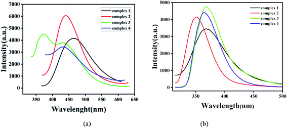
In order to investigate the luminescence properties of complexes 1–4, the solid-state photoluminescent spectra of these complexes and free ligands (H3CIA, 4,4′-bipy, 1,4-bibz, 4,4′-bbpy, 4,4′-bimp) were performed on a F7100 spectrofluorophotometer at room temperature. The emission of the free ligands (H3CIA, 4,4′-bipy, 1,4-bibz, 4,4′-bbpy, 4,4′-bimp) are displayed in Fig. S4.† For the free ligand H3CIA, the maximum peak was centered at 321 nm (λex = 361 nm), while the N-donor auxiliary ligands 4,4′- bipy, 1,4-bibz, 4,4′-bbpy, 4,4′-bimp had emission peaks at 474 nm (λex = 390 nm), 322 nm (λex = 280 nm), 403 nm (λex = 264 nm), and 342 nm (λex = 302 nm), respectively. As shown in Fig. 6a, the emission spectra of complexes 1–4 exhibited different peaks from the free ligands. For 1, there was one broad and strong peak at 465 nm (λex = 315), which could be mainly attributed to the π → π* transition of 4,4′-bipy, compared with those of the free ligands H3CIA and 4,4′-bipy. The emission peak of 2 was also a single broad and strong peak at 440 nm (λex = 322 nm), which arises with a large red-shift from the ligands H3CIA and 1,4-bibz, but it should belong to the intra-ligands transition of the organic ligands. The emission main peak at 373 nm and one shoulder peak at 430 nm (λex = 326 nm) of 3 were closer to that of 4,4′-bbpy, and complex 4 with one peak at 432 nm (λex = 321 nm), which was higher than those of H3CIA and 4,4′-bimp ligands, which all could be due to the π → π* transitions of the organic ligands. The emission spectra of 1–4 in suspension aqueous solution were investigated and the results shown in Fig. 6b, which slightly differ from those in the solid state due to the effect of the solvent. The excitation spectra of complexes 1–4 are exhibited in Fig. S5.†
 |
| | Fig. 6 Emission spectra of complexes 1–4 (a) in the solid state; (b) in the liquid state. | |
Nitrobenzene explosive sensing
Nitrobenzene is an organic synthesis intermediate and is used as a raw material for producing aniline, and so is widely used in the organic synthesis industry. However, nitrobenzene is highly toxic, causing great harm to humans and biological environments, so the rapid detection of nitrobenzene is of great significance. Mixtures of the powders of complexes 1–4 (3 mg) and water (10 mL) were treated by an ultrasonic method for 1 h and then left standing in air for 24 h to form the suspension of the MOF aqueous solution. Then a stable suspension was formed, and the top liquid was utilized for fluorescence detection. Here, 1 mL of the supernatant of complexes 1–4 were taken and added to 20 μL different pure organic solvents with vigorous shaking for fluorescence study. Then the fluorescence qualitative analysis was carried out.
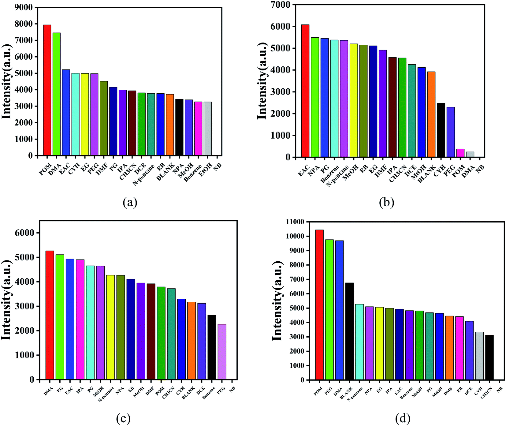
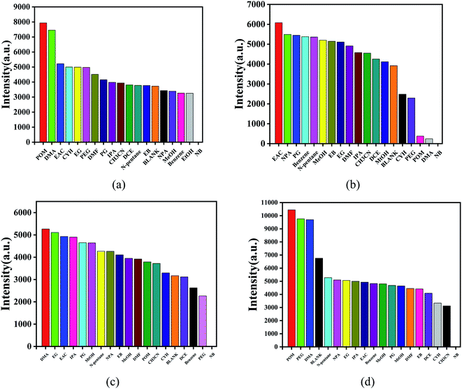
For complex 1, 370 nm specific intensity of electron transition emission was selected to evaluate the fluorescence response at the excitation of 305 nm (Fig. 7a). In Fig. 7b, for complex 2, the electron transition emission ratio intensity of 327 nm was selected to evaluate the fluorescence response under 269 nm excitation. As shown in Fig. 7c, for complex 3, the specific intensity of electron transition emission at 348 nm was selected to evaluate the fluorescence response at an excitation of 285 nm. For complex 4, the specific intensity of electron transition emission at 267 nm was selected to evaluate the fluorescence response when excited at 305 nm (Fig. 7d). The characteristic fluorescence emission intensity was obviously affected by the series of organic molecules, especially nitrobenzene. For all the complexes, the mixtures containing nitrobenzene showed a complete quenching effect, and complex 4 had the highest selectivity for nitrobenzene than the other complexes, as shown in Fig. 7.
 |
| | Fig. 7 Fluorescence qualitative selection for different organic solvents of complexes. | |
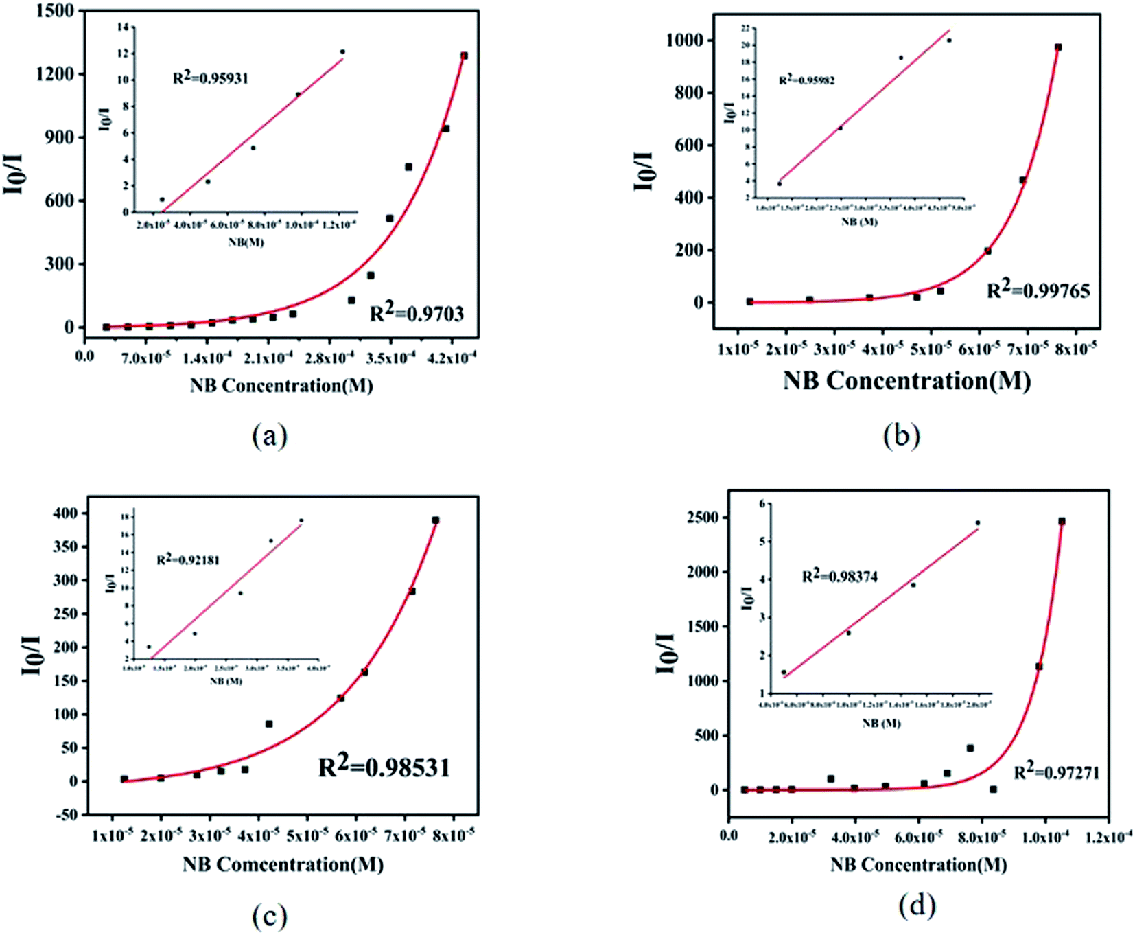
For further analysis, all the complexes were quantitatively analyzed with nitrobenzene (NB) to gain a deeper understanding of the sensing properties. Then NB with a concentration of 5 mmol L−1 ethanol solution was added in the suspension of complex 1 (1 mL) and complexes 2–4 (2 mL) in turn, respectively, to measure the change in fluorescence intensity. As the volume of NB solution increased, the fluorescence emission intensity of 1–4 decreased gradually (Fig. 8). For complex 1, when 5 μL NB was added, the luminescence intensity was quenched by 43%. When 105 μL NB was added, the luminescence intensity was quenched absolutely. In addition, a dose–response diagram in the whole titration region was found to be ideally consistent with the exponential function I0/I = −5.25 × (1−e12719.02[NB]) (where I0 and I represent luminescence intensities of water suspension of complex 1 before and after exposure to NB, respectively). Besides, a good linear correlation (R2 = 0.9703) was observed in the concentration range 0–0.098 mM with the quenching constant KSV of 1.19 × 10⁵ M−1 (Fig. 9a inset). The detection limit (LOD) for NB was 1.47 × 10⁻⁷ M as calculated by 3δ/KSV, where δ is the standard deviation of the repeated detections of the bare solutions. For complex 2, the luminescence intensity quenched reached 73% when 5 μL nitrobenzene was added and then was completely quenched with 34 μL. Furthermore, the dose–response diagram in the entire titration area was ideally consistent with the exponential function I0/I = −0.24 × (1 − e108716.14[NB]). In addition, a good linear correlation (R2 = 0.9598) was observed in the concentration range 0–0.074 mM, where the quenching constant KSV was 5.127 × 10⁵ M−1 (Fig. 9b inset), and the detection limit (LOD) for NB of 2 was 1.42 × 10⁻⁷ M. For complex 3, the luminescence intensity quenched was 70% when 5 μL NB was added, and was then completely quenched with 35 μL NB. The dose–response diagram in the entire titration area was ideally consistent with the exponential function I0/I = 6.29 × e−[NB]/−1.84×105–12.54). In addition, a good linear correlation (R2 = 0.9218) was observed in the concentration range 0–0.037 mM, where the quenching constant KSV was 6.18 × 10⁵ M−1 (Fig. 9c inset), and the detection limit (LOD) for nitrobenzene was 3.03 × 10⁻⁸ M. When 2 μL NB was added, the luminescence intensity of complex 4 was quenched by 36% and was then quenched absolutely when 43 μL nitrobenzene was added. In addition, the dose–response diagram in the whole titration region was ideally consistent with the exponential function I0/I = 0.03 × e108757.11[NB]. A good linear correlation (R2 = 0.9837) was observed in the concentration range 0–0.0199 mM, with the quenching constant KSV as 2.62 × 10⁵ M−1 (Fig. 9d inset), and the detection limit (LOD) for nitrobenzene was 1.92 × 10⁻⁷ M.
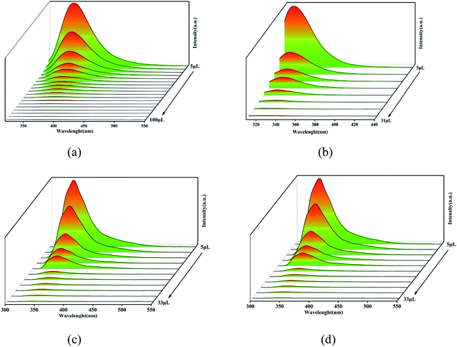 |
| | Fig. 8 Concentration-dependent luminescence quenching of complexes 1 (a), 2 (b), 3 (c), and 4 (d) suspensions in water by nitrobenzene (NB). | |
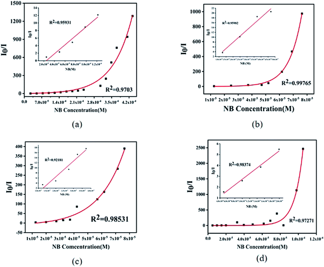 |
| | Fig. 9 Exponential function of fluorescence quantitative detection of complexes 1 (a), 2 (b), 3 (c), and 4 (d) suspensions in water quenched by nitrobenzene (NB) (inset: linear S–V plot of I0/I vs. NB in low concentration intervals). | |
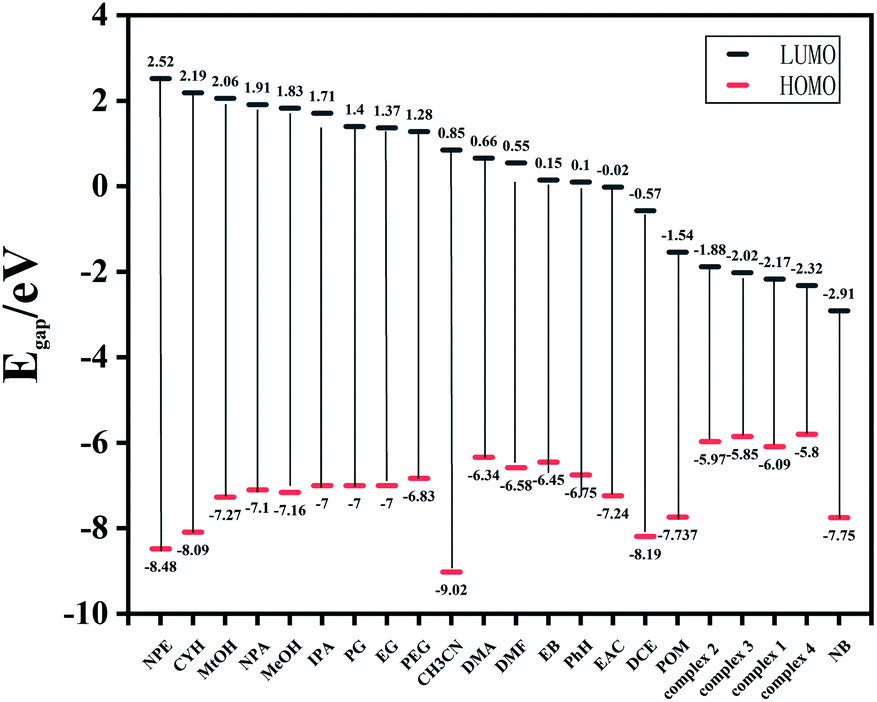
To elucidate the highly selectivity of complexes 1–4 for NB, the mechanism of fluorescence quenching was investigated. After 4 weeks of dispersion in deionized water, the fluorescence intensity of the suspension of the Zn-MOFs aqueous solution almost did not decrease, which might mean there was no obvious structural collapse, thus showing the stability of the Zn-MOFs in water (Fig. S5†). As shown in Fig. S6,† the PXRD patterns of the samples soaked and not soaked in nitrobenzene solutions were similar, indicating that the structure collapse might not be the main reason for the fluorescence quenching. Generally, there are three factors that lead to the fluorescence quenching behavior of fluorescent materials: structural change, photoinduced electron transfer (PET), and energy transfer. By Density Functional Theory, we calculated the frontier orbitals (HOMO and LUMO) energy levels of various organic solvents and complexes 1–4 (Fig. 10). From the calculated results, we found the other organic solvents possessed a higher LUMO energy level than complexes 1–4, except from NB. The lower the LUMO energy of the analyte is, the easier the transition of the excited-state electrons is. Thus, the electron may transfer from the framework to the NB under photo-induction, which is considered as the PET effect causing the fluorescence quenching of NB.20
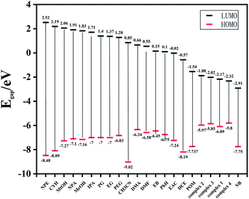 |
| | Fig. 10 HOMO–LUMO energy levels and molecular frontier orbital energy–level diagram of each organic solvent and complexes 1–4. | |
Conclusions
A series of Zn-MOFs were prepared hydrothermally with 5-(2-carboxy- benzyloxy) isophthalic acid (H3CAI) and four linear N-donor ligands. Complexes 1–4 exhibited 2D networks with different features resulting from the different coordination modes of the H3CAI ligand and different linear N-donor ligands. The thermal stabilities and fluorescent properties of all the complexes were investigated in the solid state. The fluorescent detection of organic solvents revealed that all the Zn-MOFs could highly sensitively and selectively detect nitrobenzene in aqueous solution with LOD values of 0.147 μM (1), 0.142 μM (2), 0.0303 μM (3), and 0.192 μM (4), which means these MOF materials might be used as the sensor for nitrobenzene in the future. The PET effect might be the main reason for the fluorescence quenching of NB, as verified by the theoretical calculation.
Conflicts of interest
There are no conflicts to declare.
Acknowledgements
This work was supported by National Natural Science Foundation of China (No. 22063010 and 21763028).
Notes and references
- Y. Liu, X. Xie, C. Cheng, Z. Shao and H. Wang, J. Mater. Chem. C, 2019, 7, 10743–10763 RSC.
- I. Takayuki, K. Takashi, M. Shin-ichi, N. Takashi, Y. Kizashi and I. Hiizu, Dalton Trans., 2002, 3177–3186 Search PubMed.
- A. Mahsa, R. J. Niu, W. H. Zhang and I. P. Lang, Polyhedron, 2018, 153, 218–225 CrossRef.
- D. S. Liu, M. Li, X. C. Li and F. J. Ren, Chem. Eng. J., 2020, 387, 124008–124011 CrossRef CAS.
- S. A. A. Razavi and A. Morsali, Coord. Chem. Rev., 2020, 415, 213299–213342 CrossRef CAS.
- S. Shirin, W. Jun and C. J. Peter, J. Solid State Chem., 2020, 293, 121762–121763 Search PubMed.
- J. K. Ying, L. Dong, H. L. Yue and H. C. Guang, J. Solid State Chem., 2019, 278, 120891–120892 CrossRef.
- Y. Zhou, Q. Yang, D. N. Zhang, N. Gan and Q. Li, Sens. Actuators, B, 2018, 261, 137–143 Search PubMed.
- X. Lian and B. Yan, Sens. Actuators, B, 2019, 281, 168–174 CrossRef CAS.
- X. Y. Xu, B. Yan and X. Lian, Nanoscale, 2018, 10, 13722–13729 RSC.
- S. S. Zhao, J. Yang, Y. Y. Liu and J. F. Ma, Inorg. Chem., 2016, 55, 2261–2273 CrossRef CAS.
- R. W. Corkery, Curr. Opin. Colloid Interface Sci., 2008, 134, 288–302 CrossRef.
-
(a) Z. C. Hu, B. J. Deibert and J. Li, Chem. Soc. Rev., 2014, 43, 5815–5840 RSC;
(b) K. Vellingiri, D. W. Boukhyalov, S. K. Pandey, A. Deep and K. H. Kim, Sens. Actuators, B, 2017, 245, 305–313 CrossRef CAS;
(c) E. Holmgren, H. Carlsson, P. Goede and C. Crescenzi, J. Chromatogr. A, 2005, 1099, 127–135 CrossRef CAS;
(d) S. S. Li, J. H. Fang, L. Li, M. Zhu, F. Zhang, B. Y. Zhang, T. J. Jiang and Y. X. Zhang, Talanta, 2021, 225, 122087 CrossRef CAS PubMed.
-
(a) Z. Sun, J. Sun, L. Xi, J. Xie, X. F. Wang, Y. Ma and L. C. Li, Cryst. Growth Des., 2020, 20, 5225–5234 CrossRef CAS;
(b) S. L. Sun, X. Y. Sun, Q. Sun, E. Q. Gao and L. Li, J. Solid State Chem., 2020, 292, 121701–121708 CrossRef CAS;
(c) Y. H. Yang, G. J. Ren, W. H. Li, D. X. Gu, Z. Q. Liang, Y. F. Liu and Q. H. Pan, Polyhedron, 2020, 185, 114599–114606 CrossRef CAS;
(d) L. R. Yang, C. Lian, X. F. Li, Y. Y. Han, L. L. Yang, T. Cai and C. Y. Shao, ACS Appl. Mater. Interfaces, 2017, 9, 17208–17217 CrossRef CAS PubMed.
- C. B. Fan, X. Zhang, N. N. Li, C. G. Xu, R. X. Wu, B. Zhu, G. L. Zhang, S. Y. Bi and Y. H. Fan, J. Pharm. Biomed. Anal., 2020, 188, 113444–113458 CrossRef CAS PubMed.
-
(a) S. J. Wang, H.
L. Wu, L. X. You, G. Xiong, Y. K. He, F. Ding and Y. G. Sun, Inorg. Chim. Acta, 2019, 485, 49–51 CrossRef CAS;
(b) J. Z. Gu, Y. Cai, M. Wen, Z. F. Shi and A. M. Kirillov, Dalton Trans., 2018, 47, 14327–14339 RSC;
(c) X. Mi, D. Sheng, S. Wang, J. Lu, L. Yang and Z. Zhou, Acta Crystallogr., Sect. C: Struct. Chem., 2019, 75, 657–666 CrossRef CAS.
- SAINT-Plus, version 6.02, Bruker Analytical X-ray System, Madison, WI, 1999 Search PubMed.
-
(a) Bruker AXS. Inc., Madison, WI, 2013;
(b) G. M. Sheldrick, Acta Crystallogr., Sect. A: Found. Crystallogr., 2008, 64, 112–122 CrossRef CAS;
(c) XSHELL, version 4.01 and SHELXTL, version 6.10 Search PubMed;
(d) Bruker AXS, Inc., Madison, WI, 2000.
- G. M. Sheldrick, SADABS, Program for Empirical Absorption Correction of Area Detector Data, University of Göttingen, Germany, 1996 Search PubMed.
- G. Qin, J. Wang and L. Li, Talanta, 2020, 221, 121421 CrossRef PubMed.
Footnote |
| † Electronic supplementary information (ESI) available: Bond lengths and bond angles data table, TG curves, PXRD patterns, the emission of the free ligands, Fluorescence time diagrams. CCDC numbers of complexes 1–4 are 2046401–2046404. For ESI and crystallographic data in CIF or other electronic format see DOI: 10.1039/d1ra03737d |
|
| This journal is © The Royal Society of Chemistry 2021 |
Click here to see how this site uses Cookies. View our privacy policy here. 
 Open Access Article
 This Open Access Article is licensed under a Creative Commons Attribution-Non Commercial 3.0 Unported Licence
 *,
Hongmei Chai,
Xiufang Hou*,
Zhixiang Wang and
Jijiang Wang
*,
Hongmei Chai,
Xiufang Hou*,
Zhixiang Wang and
Jijiang Wang