
 Open Access Article
 This Open Access Article is licensed under a Creative Commons Attribution-Non Commercial 3.0 Unported Licence
Productive preparation of N-doped carbon dots from sodium lignosulfonate/melamine formaldehyde foam and its fluorescence detection of trivalent iron ions
Yong-Yan Pan†
a,
Wei-Ming Yin† a,
Ran-Jun Menga,
Yuan-Ru Guo*a,
Ji-Guo Zhang*a and
Qing-Jiang Pan*b
a,
Ran-Jun Menga,
Yuan-Ru Guo*a,
Ji-Guo Zhang*a and
Qing-Jiang Pan*b
aKey Laboratory of Bio-based Material Science & Technology (Ministry of Education), Material Science and Engineering College, Northeast Forestry University, Harbin 150040, China. E-mail: guoyrnefu@163.com; 116920813@qq.com
bKey Laboratory of Functional Inorganic Material Chemistry (Ministry of Education), School of Chemistry, Chemical Engineering and Materials, Heilongjiang University, Harbin 150080, China. E-mail: panqjitc@163.com
First published on 7th July 2021
Abstract
Due to its good properties and low cost, melamine formaldehyde foam has been widely used in cars, furniture and construction. However, how to recycle the spent foam still remains challenging for scientists. In this work, a new method was designed to prepare N-doped carbon dot (NCD) materials by calcining sodium lignin sulfonate/melamine formaldehyde foam (LSMF) via one step. TEM, IR and XPS were used to characterize the structure and morphology of newly-synthesized NCDs. It is shown that carbon powder is obtainable by calcination. Since it derives from the collapse of the foam structure of LSMF, the carbon powder can almost completely dissolve in deionized water. The particle size ranges from 5 to 20 nm. The fluorescence properties of NCDs were studied by fluorescence spectroscopy. A strong emission has been detected at 580 nm with the quantum yield of 2.94%. When applying NCDs to detect various metal ions, there is a significant fluorescence quenching effect and good selectivity for Fe3+. The mechanism has been hypothesised. Our study provides a method for productive preparation of NCDs from spent foam.
Introduction
Environmental pollution is a major issue in the 21st century.1,2 How to efficiently use existing resources and achieve “turning waste into treasure” is the research goal of many researchers.3 Melamine formaldehyde foam (MF) is a thermosetting polymer foam with excellent flame retardancy and high corrosion resistance. Because of its high porosity and sound insulation and thermal insulation properties, MF is widely used in the construction industry.4,5 In order to use the environmentally friendly MF, many methods have been applied for its preparation. For example, Zhang et al.6 prepared a new type of microencapsulated phase change material using paraffin wax as the core and hydrophobic silicon carbide modified MF resin as the shell. The uniform distribution of H–SiC on the surface of the microcapsules has an effect on the heat conduction and heat dissipation of the microcapsules. In the work of Zhu et al.,7 ethylene glycol was used to modify MF resin, and the product was made to a filler; further association with polyols and polyisocyanates prepared rigid polyurethane foams.However, how to prepare MF in an environmentally friendly route or how to reuse MF to achieve the “sustainable” development is still a problem for scientists to face with. Some strategies have been adopted to fulfil this goal, for instance, using bioresource lignin. Lignin, as the second largest natural polymer on earth, was applied to produce MF, which reduced the addition of formaldehyde. Compared with other biopolymers, lignin has the advantages of biocompatibility as well as high carbon content.1,8 The introduction of lignin can reduce the production cost of MF and the release amount of formaldehyde. However, it can't solve the recycle problem of spent foam. More work is encouraged to work on this aspect.
Iron ion, Fe3+ for instance, is one of the indispensable trace elements in human life. The recommended intake of iron ranges from 8 to 18 mg per day for normal adult. But excessive intake of iron will cause iron poisoning.9 Moreover, Fe3+ cannot be metabolized in the human body, which can lead to serious liver and kidney damage and even death.10 Carbon dots (CDs) are soluble and fluorescent nanoparticles, which were firstly reported by Xu et al.11 As a new type of zero-dimensional nanomaterial, CDs bears a graphite phase core, and its surface is full of hydrophilic groups such as hydroxyl and carboxyl groups,12–14 which bring the fascinating property of CDs. CDs has been applied as fluorescence sensor for detecting various metal ions due to the abundant active sites on its surface.15
Taking advantage of the rich carbon source of waste foam, we used a one-step calcination method to prepare nitrogen doped carbon dots (NCDs) from sodium lignosulfonate/melamine formaldehyde foam (LSMF). The newly-obtained NCDs show intensive fluorescence and preferential detection performance on iron ion over other common s/d-block metal ions. The synthetic route and testing has been shown in Scheme 1. The work provides a reasonable solution to the problem of recycling of waste LSMF and achieves the purpose of rational utilization of resources.
 | ||
| Scheme 1 Preparation of NCDs and quenching effect by Fe3+ ions. | ||
Results and discussion
In order to study the structure of materials before and after sintering, XRD was performed and result is shown in Fig. 1a. It can be seen that LSMF has a broad peak at 19–26°, indicating that LSMF is an amorphous polymer material. However, a relative sharp peak near 2θ = 25.6° was observed after calcination, which is corresponding to the (002) plane of graphite carbon.16–18 The change of XRD plots shows that the LSMF has transformed into carbon material.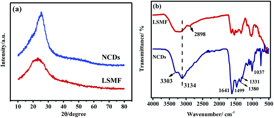 | ||
| Fig. 1 The XRD patterns (a) and FT-IR spectra (b) of the LSMF and NCDs. | ||
IR was also applied to study the functional groups of both LSMF and NCDs, as shown in Fig. 1b. To LSMF, the main absorption bands of LSMF at 1450–1600 cm−1 correspond to the triazine ring, and the absorption peak at 2898 cm−1 is vibration of –CH2/–CH3. The peaks around 3100 and 3300 cm−1 are –OH and –NH vibration. Due to large molecular skeleton, these two peaks connected to each other and formed a broad peak. To the IR spectrum of NCDs, these two peaks are totally separated. Moreover, the intensity of –OH was enhanced, which indicated that more –OH groups found on NCDs. Meanwhile, multiple peaks are found in functional group region, peaks at 1641 cm−1 are vibration of C![[double bond, length as m-dash]](https://www.rsc.org/images/entities/char_e001.gif) C group of the aromatic ring, the absorption peaks at 1380 cm−1 and 1331 cm−1 are derived from the stretching vibration of C–N, peaks at 1499 cm−1 are the flexural vibration absorption peaks of sp2 hybrid C framework. The absorption peak at 1037 cm−1 is related to the C–O–C ether bond.
C group of the aromatic ring, the absorption peaks at 1380 cm−1 and 1331 cm−1 are derived from the stretching vibration of C–N, peaks at 1499 cm−1 are the flexural vibration absorption peaks of sp2 hybrid C framework. The absorption peak at 1037 cm−1 is related to the C–O–C ether bond.
SEM is applied to characterize the morphology of both LSMF and NCDs. It can be seen in Fig. 2a and b that LSMF foam is constructed by hollow ball, which has diameter about 2.5 μm. And these balls connected to each other and form the network. The hollow spherical structure of foam makes it excellent thermal insulation material on one hand, it also makes itself easy to be decompose to CDs on the other hand. After treated at 250 °C, the foam structure collapsed and pieces of carbon can be obtained as can been seen in Fig. 2c and d. Though CDs was formed at this stage, these CDs are still clustered together and maintaining a collapsed cross-linked structure. Once dissolved in distilled water and ultrasound treated for 30 min, almost all the carbon dissolved into water and result in yellow solution. This gives the evidence that carbon dots can been prepared by simply heated the LSMF at 250 °C by solid reaction. Since there are abundant of C–OH, C–N–H and CO functional groups on the surface, the prepared NCDs shows high solubility. After centrifugation and removal of the residue, a yellow transparent NCDs solution can be obtained.
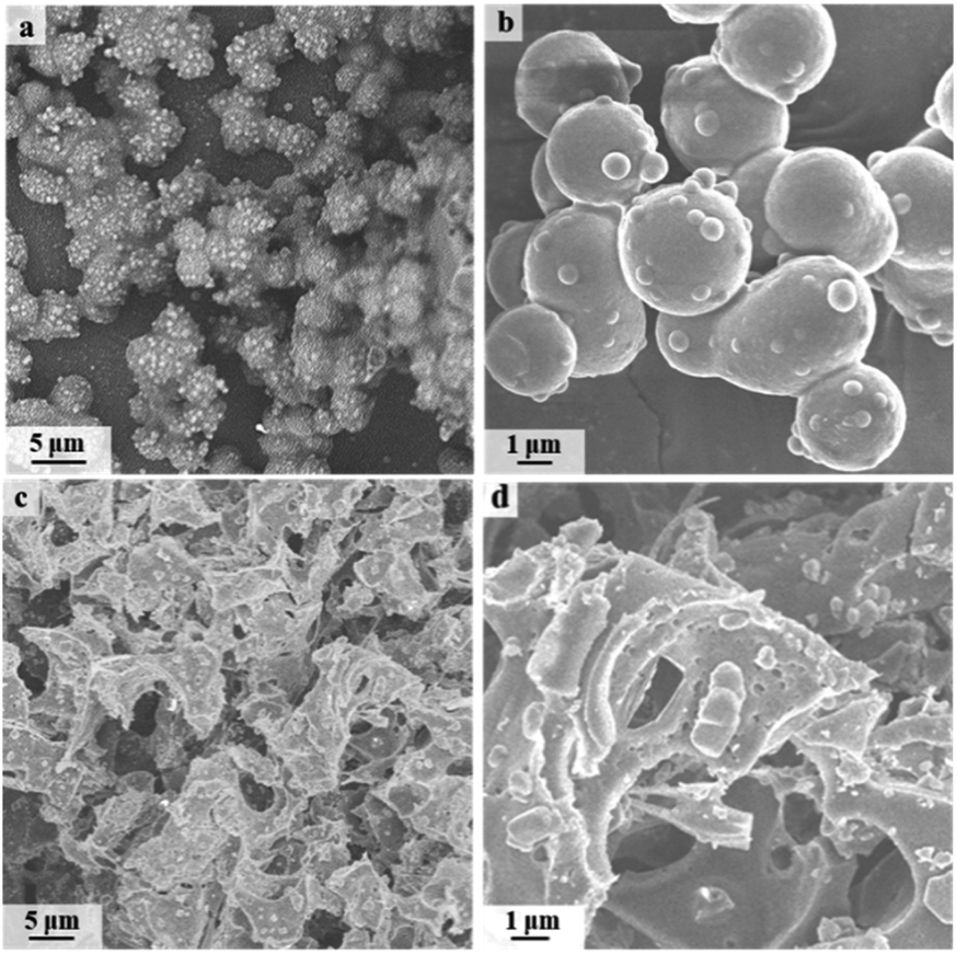 | ||
| Fig. 2 SEM images LSMF (a and b) and NCDs (c and d). | ||
TEM was applied to further analyse the structure of NCDs and the results are shown in Fig. 3. It can be seen that the NCDs we prepared has good dispersibility, and the particle size ranges from 5 to 20 nm. In the high-resolution image, clear lattice fringes can be found with the crystal plane spacing of 0.21 nm, which corresponds to the (002) crystal plane of graphite. Combined with infrared analysis results, the prepared NCDs have sp2 hybrid graphite cores.
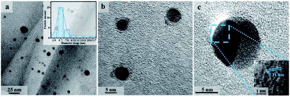 | ||
| Fig. 3 TEM images of NCDs (a and b), along with the HRTEM image (c). | ||
XPS was applied to explore the doping elements in NCDs and their chemical environment, as shown in Fig. 4. According to XPS analysis, NCDs mainly contain C, O, N elements. Fig. 4a is C 1s spectrum of NCDs. It is fitted to five peaks with binding energies of 284.4, 285.2, 286.7 and 288.2 eV. The first peak belongs to the C–C bond, which indicates that the prepared NCDs contains the sp2 hybrid graphite carbon phase. The following two correspond to binding energies of C–H and O–CO, respectively. And the last peak at 288.2 eV indicates the existence of C–O bond. The O 1s spectrum (Fig. 4b) can be fitted for four peaks at 530.5, 531.5, 532.3 and 533.3 eV, which are assigned to C–O, O–H, C–O–C and O–CO, respectively. The relative strong peaks also give the evidence that there are plenty of oxygen containing functional groups on NCDs. The spectrum of N 1s has peaks at binding energy of 397.6, 398.4 and 399.4 eV (see Fig. 4c), which are related to C![[triple bond, length as m-dash]](https://www.rsc.org/images/entities/char_e002.gif) N, C–N and N–H, respectively.
N, C–N and N–H, respectively.
 | ||
| Fig. 4 XPS curves of NCDs, C 1s (a), O 1s (b) and N 1s (c). | ||
According to the XPS results, during the preparation of NCDs by solid-phase sintering, new functional groups were introduced on the surface of NCDs. These functional groups provided fluorescence emission centres for NCDs, which matched the results of the subsequent fluorescence spectrum analysis.
In order to explore the fluorescence properties of the prepared NCDs, both ultraviolet spectroscopy and fluorescence spectroscopy were used to characterize NCDs. Fig. 5a shows the scan results of the UV and fluorescence spectra of NCDs. According to the literature,15,19 the absorption peaks of NCDs at 212 nm and 251 nm are caused by the π–π* transition originated from sp2 hybridized C. A adsorption with relatively low intensity around 280–300 nm, which is mainly caused by the n–π* transition of CO/C–N. Generally, the fluorescence emission mechanism of CDs mainly involves three aspects: the size effect of CDs, the electronic transition of sp2 hybrid carbon nuclei, and the surface passivation.20
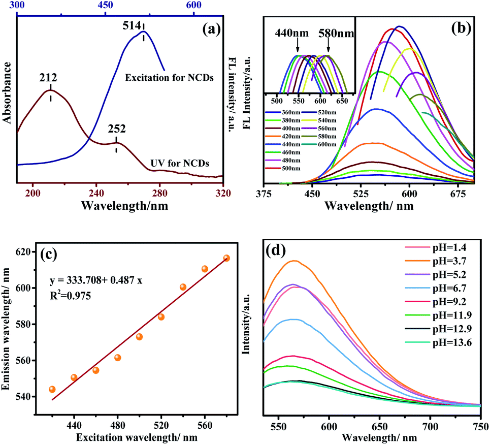 | ||
| Fig. 5 UV-Vis and fluorescence spectra of NCDs (a), fluorescence spectra excited by various wavelengths (b), and the insert picture is the plot after normalization, the linear correlation plot of excitation versus emission (c) and fluorescence spectra while varying solution pH value (d). | ||
The fluorescence excitation spectrum of NCDs is also shown in Fig. 5a. It can be seen that NCDs have the strongest fluorescence emission peak under excitation at 514 nm. Since the strongest emission of CDs may affect by excitation wavelength, the emission spectra of NCDs at different excitation wavelengths were also performed. As shown in Fig. 5b and c, the emission of NCDs has a significant red shift with the increase of excitation wavelength. The “excitation wavelength dependence” phenomenon occurs due to the complex surface state of NCDs: the dominant emission site on the surface of NCDs changes accordingly and lead to different emission wavelengths when excited at different excitation wavelengths.21 Calcination process makes the surface of the CDs passivated on one hand, on the other hand it produced abundant functional groups, which improved the fluorescence performance. Meanwhile, the N element was introduced into CDs, which increase the defect energy level on the surface of NCDs, and promote NCDs fluorescence intensities. Meanwhile, the fluorescence quantum yield of NCDs was determined to be 2.94% using the photoluminescence spectrometer.
To consider the pH effect, the fluorescence intensity was determined in the solution of different pH values. The results are presented in Fig. 5d. One can see that the NCDs exhibits the strongest intensity at pH = 3.74. Starting from it, higher pH solution affords lower fluorescence intensity. It can be attributed to the presence of more hydroxyl functional groups on the NCDs. It is known that the bonding of the hydroxyl groups to NCDs destroys the π conjugation of carbon dots and eventually lowers the transition possibility of π* → π.
Due to its good fluorescent property, the application of as NCDs as fluorescent probe to detect metal ions were also carried out the fluorescence intensity of the aqueous solution of NCDs before and after mixed with metal ions (μmol L−1) were measured by a fluorescence spectrometer and the result is shown in Fig. 6a and b. According to the results NCDs solution gives cyan-green colour. After interacting with metal ions, the fluorescence intensity of mixture decreases and colour changes to blue except of Fe3+. Fe3+ has the most obvious fluorescence quenching effect in NCDs solution. The quenching effect is also can been observed under ultraviolet light irradiation (Fig. 6b). This gives the evidence that Fe3+ can be identified from other metals ions by our NCDs.
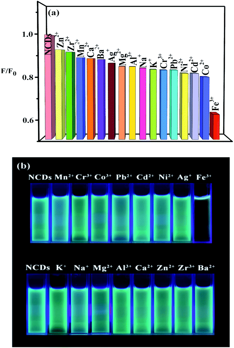 | ||
| Fig. 6 Quenching selectivity of NCDs for different metal ions, the relative fluorescence intensities (a) and the taken pictures illuminated under the 365 nm UV light (b). | ||
The fluorescence quenching mechanism of Fe3+ toward NCDs was also explored by adding 15 μL Fe3+ ions to 3 mL NCDs solution. The concentration of Fe3+ ion varies from 9, 18, 35, 45, 90, 180, 360 to 450 μmol L−1. Both Stern–Volmer (eqn (1)) and double logarithmic regression model (eqn (2)) were used to analyse the quenching mechanism.22,23 Results are shown in Fig. 7a and b.
| F0/F = 1 + KsvQ | (1) |
log(F0/F − 1) = log![[thin space (1/6-em)]](https://www.rsc.org/images/entities/char_2009.gif) K + nlogQ K + nlogQ
| (2) |
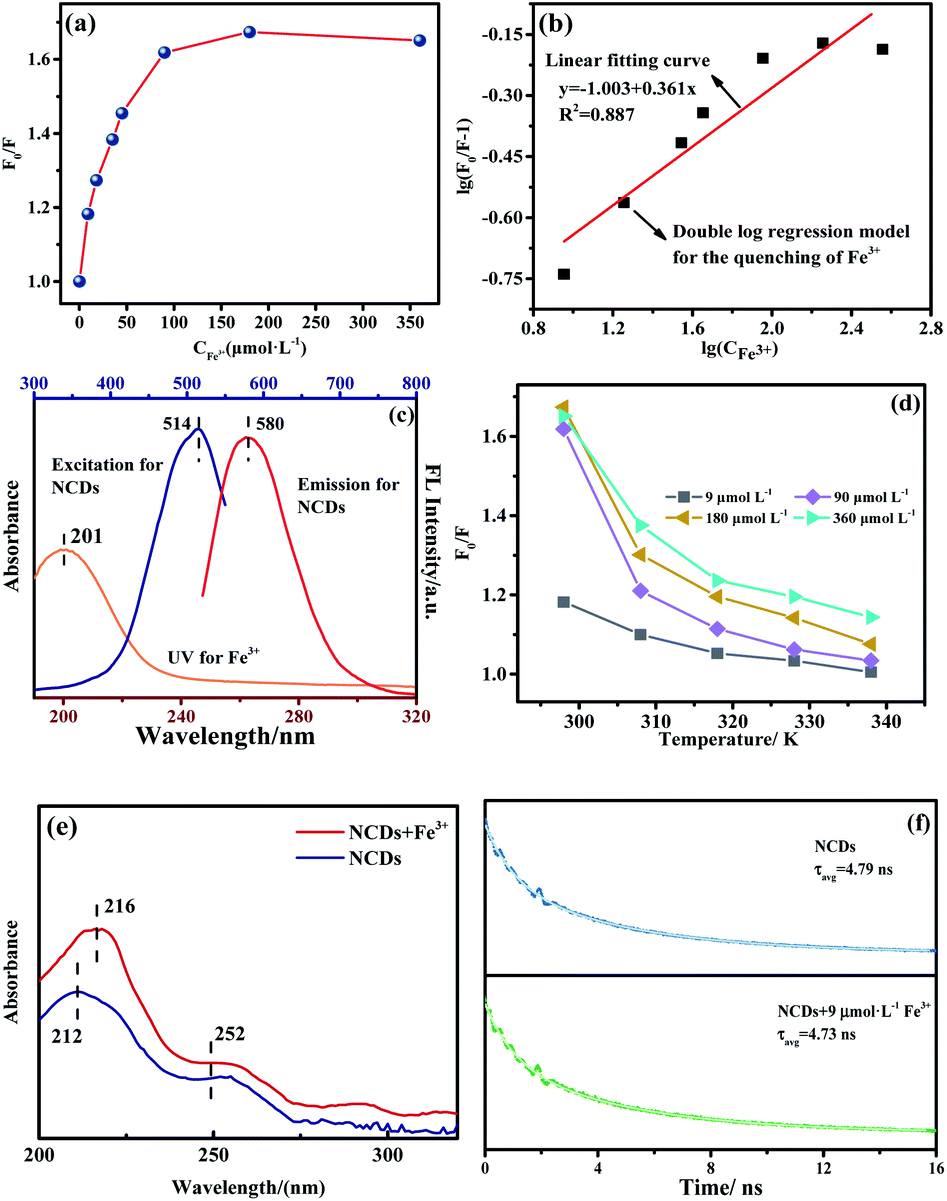 | ||
| Fig. 7 (a) The relationship of F0/F versus concentration of Fe3+ at 298 K, (b) static fitting of Fe3+ quenching for NCDs, (c) UV spectrum of Fe3+ and emission and excitation spectra of NCDs, (d) the temperature effect on quenching, (e) the UV-Vis spectra of NCDs and Fe3+-added NCDs, and (f) luminescence decay curves of NCDs with and without adding Fe3+ at λex = 500 nm and λem = 580 nm. | ||
Generally, the fluorescence quenching mechanism involves dynamic quenching, static quenching24,25 and internal filtration effect (IFE).26–29 The dynamic quenching is triggered by the collision of the quencher ion with the carboxyl, hydroxyl and other functional groups on the surface of NCDs, causing electron transfer. The static quenching is caused by the interaction of the empty orbital of the quencher ion with the π electrons of the NCDs, which can form the complex and results in fluorescence quenching.
Generally, the fluorescence quenching mechanism involves dynamic quenching, static quenching24,25 and internal filtration effect (IFE).26–29 Dynamic quenching is triggered by the collision of the quencher ion with the carboxyl, hydroxyl and other functional groups on the surface of NCDs, causing electron transfer. The static quenching is caused by the interaction of the empty orbital in the quencher ion with the π electrons of the NCDs, which can form the complex and results in fluorescence quenching.
The use of eqn (1) for fitting finds that the quenching of NCDs by Fe3+ has a large deviation, which indicates that it is not dominated by the dynamic quenching mechanism. When being fitted by the static eqn (2), the values of the related constants of K and n are 0.101 L mol−1 and 0.361, respectively, the coefficient R2 is 0.909. This suggests the static quenching involved. As a matter of fact, it is understandable that the empty virtual orbitals of the Fe3+ ion can be filled by the π electrons of the NCDs on the one hand and oxo groups on the NCDs surface as indicated in XPS (Fig. 4) on the other hand. The IFE mechanism was also explored by using the UV spectrum of Fe3+ and the emission and excitation spectra of NCDs (Fig. 7c). One can see that there is no overlap between the Fe3+ adsorption and the emission of NCDs. Evidently, this rules out the IFE quenching mechanism.
To prove the postulated static quenching mechanism, we further embarked on several experiments, including the temperature effect on the quenching (Fig. 7d), the absorption spectrum after introducing the quencher (Fig. 7e), and the effect of the quencher on the fluorescence lifetime of the NCDs (Fig. 7f).
According to Fig. 7d, one can see that the relative intensity of F0/F decreases as the temperature rises. The result indicates that the quench effect reduces once increasing temperature. This is consistent with the static quenching mechanism. In order to verify it, the adsorption spectra of the NCDs and the mixture of NCDs and Fe3+ were measured. Fig. 7e displays the difference of adsorption spectra between these two systems, which suggests that NCDs and Fe3+ have formed sort of ground-state complex. Moreover, NCDs is rich of π electrons and various oxo functional groups including CO, C–O, C–OC, O–CO and OH, which have been evidenced by the XPS spectra of Fig. 4. This provides the essential basis for complexing the iron ion in the mixture solution of NCDs and Fe3+. Focusing on the possibly formed NCDs–Fe complex, the effect of the quencher on the fluorescence lifetime was evaluated. See results of NCDs and Fe3+-added NCDs in Fig. 7f. The determined lifetime of NCDs is 4.79 ns. After adding Fe3+, the lifetime is 4.73 ns. Almost the same lifetime proves that the quenching is dominated by the static mechanism.
Conclusions
High yield of nitrogen-doped carbon dots (NCDs) was prepared by one-step calcination of lignin/melamine formaldehyde foam (LSMF) at 250 °C. The results of SEM, TEM and XRD show that prepared NCDs are uniformly dispersed with a particle size of about 10 nm. Meanwhile, NCDs has high graphitization degree and the surface is rich of functional groups, which would enhance its fluorescence properties. The fluorescence properties and detection for various metal ions were studied, revealing that prepared NCDs have a good identification of Fe3+. The corresponding fluorescence quenching mechanism was postulated as the static quenching. Due to being prepared from the spent foam with a facile method, NCDs would have good application prospect in future.Experimental
Experimental materials
Sodium lignosulfonate (LS), purchased from Qianjin Welfare Chemical Co., Ltd, Tumen City, Jilin Province; melamine, paraformaldehyde, sodium dodecyl sulfonate, ammonium chloride, triethanolamine, and petroleum ether are purchased from Tianjin Kermel Chemical Reagent Company. All reagents were used as received.Preparation
The mixture was put into the mold. 0.05 g of sodium lauryl sulfate, 4.0 g of ammonium chloride and 5 mL petroleum ether were also put into mold in sequence. After curing in an oven at 80 °C for 24 h, sodium lignosulfonate melamine formaldehyde (LSMF) foam is obtained.
Characterization
X-ray diffractometer (XRD, D/max-RC, Rigaku, Japan) was applied to characterize the structure of products. The morphology was observed by a scanning electron microscope (SEM, JSM-7500F, JEOL, Japan) and transmission electron microscope (TEM, JEM-2100, JEOL, Japan). The infrared absorption spectra were tested using Fourier transform infrared spectrometer (FT-IR, Frontier type, PerkinElmer, USA). X-ray photoelectron spectroscopy was determined by X-ray photoelectron spectroscopy (XPS, ESCALAB, Thermo, USA).UV-Vis spectroscopy test
All the UV-Vis spectra were tested with the 3 mL NCDs solution in the two-way quartz cuvette. The ultraviolet-visible spectrophotometer (TU-1950, Beijing Purkinje General Instrument, China) was used.Fluorescence spectroscopy test
Fluorescence spectrometer (LS 55, PerkinElmer, USA) was used to characterize the fluorescent emission at room temperature (298 K). All the spectra were tested with the 3 mL NCDs solution in the four-way quartz cuvette. The concentration of NCDs is 10 mg mL−1. The excitation light of 500 nm was utilized for NCDs with and without metal ions. The selectivity experiment was performed by adding metal ions including K+, Na+, Mg2+, Ca2+, Cr3+, Mn2+, Fe3+, Co2+, Ni2+, Cu2+, Zn2+, Zr2+, Cd2+, Ag+, Al3+ and Pb2+. To make the solution, 3 mL 10 mg mL−1 NCDs was mixed with the 15 μL 90 μmol L−1 metal ion solution, followed by 1 min reaction period at room temperature, the fluorescence emission response was recorded in the same condition.The temperature effect of the Fe3+ quenching was carried out at the different temperature (298, 308, 318, 328, 338, and 348 K). NCDs and Fe3+ solution were kept at the corresponding temperature for 10 min, and then reacting for 1 min. The fluorescence emission response was recorded under consistent conditions.
The luminescent lifetime and the absolute quantum yield were measured by a photoluminescence spectrometer (Edinburgh Instruments, FLS1000, England). The luminescent lifetime of τ matches with the double exponential function:30,31
| R(t) = B1e(−t/τ1) + B2e(−t/τ2) | (3) |
The average lifetime τavg is defined as:
 | (4) |
Conflicts of interest
There are no conflicts to declare.Acknowledgements
This study is supported by the National Undergraduates Training Programs of Innovation (Northeast Forestry University) (grant number 201910225056).References
- N.-D. Zhao, Y. Wang, X.-H. Zou, W.-M. Yin, X.-Y. Wang, Y.-R. Guo and Q.-J. Pan, Chem. Eng. J., 2021, 426, 130812 CrossRef CAS.
- M. Liu, C. Zhang, Z. Du and W. Zou, Comp. Interf., 2021, 28, 255–271 CrossRef CAS.
- X. T. Wang, Y. Shi, Y. Liu and Q. Wang, J. Polym. Res., 2019, 26, 57–68 CrossRef.
- H. H. Liao, H. Y. Li, Y. Liu and Q. Wang, Polym. Int., 2019, 68, 410–417 CrossRef CAS.
- X. Wang, Z. Han, Y. Liu and Q. Wang, Appl. Surf. Sci., 2020, 505, 144577–144587 CrossRef CAS.
- B. Zhang, S. Li, X. Fei, H. Zhao and X. Lou, Colloids Surf., A, 2020, 603, 125219–125225 CrossRef CAS.
- H. Zhu and S. Xu, ACS Omega, 2020, 5, 9658–9667 CrossRef CAS PubMed.
- B. Song, H. Liang, R. Sun, P. Peng, Y. Jiang and D. She, Int. J. Biol. Macromol., 2020, 144, 219–230 CrossRef CAS PubMed.
- Y.-H. Chan, Y. Jin, C. Wu and D. T. Chiu, Chem. Commun., 2011, 47, 2820–2822 RSC.
- E. L. Que, D. W. Domaille and C. J. Chang, Chem. Rev., 2008, 108, 1517–1549 CrossRef CAS PubMed.
- X. Xu, R. Ray, Y. Gu, H. J. Ploehn, L. Gearheart, K. Raker and S. A. Walter, J. Am. Chem. Soc., 2004, 126, 12736–12737 CrossRef CAS PubMed.
- M. Lu and L. Zhou, ACS Omega, 2019, 101, 352–359 CAS.
- C. A. Ma, C. S. Yin, Y. J. Fan, X. F. Yang and X. P. Zhou, J. Mater. Sci., 2019, 54, 9372–9384 CrossRef CAS.
- W.-M. Yin, Y. Wang, Y.-C. Hou, Y. Sun, J.-G. Zhang, H.-L. Sun, S.-J. Li, Q.-J. Pan and Y.-R. Guo, Chem. Eng. J., 2020, 401, 125961–125970 CrossRef CAS.
- H. Qi, M. Teng, M. Liu, S. Liu, J. Li, H. Yu, C. Teng, Z. Huang, H. Liu, Q. Shao, A. Umar, T. Ding, Q. Gao and Z. Guo, J. Colloid Interface Sci., 2019, 539, 332–341 CrossRef CAS PubMed.
- D. Pan, J. Zhang, Z. Li and M. Wu, Adv. Mater., 2010, 22, 734–738 CrossRef CAS PubMed.
- L. Li, G. Wu, G. Yang, J. Peng, J. Zhao and J.-J. Zhu, Nanoscale, 2013, 5, 4015–4039 RSC.
- Y. Dong, H. Pang, H. B. Yang, C. Guo, J. Shao, Y. Chi, C. M. Li and T. Yu, Angew. Chem., Int. Ed., 2013, 52, 7800–7804 CrossRef CAS PubMed.
- M. Saxena and S. Sarkar, Diamond Relat. Mater., 2012, 24, 11–14 CrossRef CAS.
- Y.-P. Sun, B. Zhou, Y. Lin, W. Wang, K. A. S. Fernando, P. Pathak, M. J. Meziani, B. A. Harruff, X. Wang, H. Wang, P. G. Luo, H. Yang, M. E. Kose, B. Chen, L. M. Veca and S.-Y. Xie, J. Am. Chem. Soc., 2006, 128, 7756–7757 CrossRef CAS PubMed.
- Z. Liang, L. Zeng, X. Cao, Q. Wang, X. Wang and R. Sun, J. Mater. Chem. C, 2014, 2, 9760–9766 RSC.
- R. S. A. Sonthanasamy, N. M. N. Sulaiman, L. L. Tan and A. M. Lazim, Spectrochim. Acta, Part A, 2019, 218, 85–96 CrossRef CAS PubMed.
- D. Saha and D. P. S. Negi, Chem. Phys., 2020, 530, 110644–110649 CrossRef CAS.
- J. R. Lakowicz, Principles of fluorescence spectroscopy, Springer science & business media, 2013 Search PubMed.
- W. Liu, H. Diao, H. Chang, H. Wang, T. Li and W. Wei, Sens. Actuators, B, 2017, 241, 190–198 CrossRef CAS.
- F. L. Zu, F. Y. Yan, Z. J. Bai, J. X. Xu, Y. Y. Wang, Y. C. Huang and X. G. Zhou, Microchim. Acta, 2017, 184, 1899–1914 CrossRef CAS.
- H. Liu, C. Xu, Y. Bai, L. Liu, D. Liao, J. Liang, L. Liu and H. Han, Spectrochim. Acta, Part A, 2017, 171, 311–316 CrossRef CAS PubMed.
- T. D. Gauthier, E. C. Shane, W. F. Guerin, W. R. Seitz and C. L. Grant, Environ. Sci. Technol., 1986, 20, 1162–1166 CrossRef CAS.
- J. Liu, Y. Chen, W. Wang, J. Feng, M. Liang, S. Ma and X. Chen, J. Agric. Food Chem., 2016, 64, 371–380 CrossRef CAS PubMed.
- M. Li and P. R. Selvin, J. Am. Chem. Soc., 1995, 117, 8132–8138 CrossRef CAS.
- M. Kawa and J. M. J. Fréchet, Chem. Mater., 1998, 10, 286–296 CrossRef CAS.
Footnote |
| † The two authors equally contributed to this work. |
| This journal is © The Royal Society of Chemistry 2021 |