 Open Access Article
Hydrophilic modification of SLA 3D printed droplet generators by photochemical grafting†
Tristan W. Bacha ,
Dylan C. Manuguerra,
Robert A. Marano and
Joseph F. Stanzione III*
Department of Chemical Engineering, Rowan University, 201 Mullica Hill Rd, Glassboro, NJ 08028, USA. E-mail: stanzione@rowan.edu
First published on 18th June 2021
Abstract
Few droplet generators manufactured using desktop stereolithography 3D printers have been reported in the literature. Moreover, 3D printed microfluidic chips are typically hydrophobic, limiting their application to water in oil droplets. Herein, we present designs for concentric and planar 3D printed microfluidic devices suitable for making polymeric microparticles using an off-the-shelf commercial stereolithography printer and resin. The devices consist of a microscope slide, binder clips, and printed components. Channels were modified by an ultraviolet grafting of methacrylic acid to the surface of chips, yielding a hydrophilic coating without modification to the bulk polymer. The water contact angle decreased from 97.0° to 25.4° after grafting. The presence of the coating was confirmed by microscopy and spectroscopy techniques. Polystyrene microparticles in the <100 μm size range were generated with varying molecular weights using the described microfluidic chips. Our work provides a facile method to construct droplet generators from commercial stereolithography printers and resins, and a rapid surface modification technique that has been under-utilized in 3D printed microfluidics. A wide range of microfluidic devices for other applications can be engineered using the methods described.
Introduction
Classic methods of manufacturing microfluidic devices are cumbersome, requiring many steps and highly specialized equipment. Photolithography is a common method to make micro-scale moulds for casting PDMS microfluidic devices.1 The cost and complexity of photolithography makes it impractical for new laboratories, or researchers looking to easily incorporate microfluidics into a part of their work. Milling microfluidic devices and moulds is another option for device production, but this method requires a high precision CNC mill and replication techniques.2 Although outsourcing micromachining or photolithography sources is possible, in-house techniques are preferred when a device may take several iterations to develop.3D printing is an attractive solution for manufacturing microfluidic chips because of the availability of affordable desktop printers. Recently, 3D printing has been utilized to create microfluidic devices for healthcare, chemistry, and engineering applications.3–5 3D printing is fast, simple, low cost, and can produce 3D structured polymer microchips that are resistant to swelling in solvents.6–8 PDMS is known to swell in many organic solvents, which limits its application in microfluidics. Swelling is of utmost concern in droplet generators because of the strong dependence of droplet formation on channel dimensions.
Droplet generators have a broad range of uses spanning multiple fields including engineering, chemistry, biology, food, and medicine.9–11 Because of the expansive applicability of droplet generators, simple and accessible methods of producing them are highly appealing to many research groups. Herein, we report the design, surface treatment, and assembly of simple and quick to produce oil in water (o/w) droplet generators utilizing an inexpensive commercial desktop 3D printer. Our design does not require a modified 3D printer or resin system and can produce polymer particles in the sub 100 μm size range with narrow size distributions. Furthermore, our methodology can be extended to enable rapid fabrication of fluidic devices other than droplet generators.
Recently, several 3D printed droplet generators have been reported using mostly stereolithography apparatus (SLA) or direct light projection (DLP) printers. Fused deposition modelling (FDM) is also used, but printable feature size is poor compared to SLA.1,12 The reported droplet generator designs encompass 3D structures,7,8,13–17 planar structures, and modular designs.13,16 Other droplet generators utilize 3D printing for either device mould making,18,19 or parts to make hybrid devices.20–23 The hybrid devices utilize tubing, capillaries, or needles to facilitate droplet production.
Purely 3D printed chips with the smallest feature sizes require custom 3D printers and resins. The smallest feature sizes are achieved using microstereolithography,11 modified 3D printers and resins,24 and high-end or custom 3D printers.14,16,25,26 Channel sizes down to 18 × 20 μm have been reported with custom setups.25 Smaller channel sizes are more difficult to obtain with commercial desktop printers. These channels are typically on the order of several hundred microns in size.7,8,13,15,17,27
To produce droplets, the dispersant should wet the device preferentially to the dispersed phase. Only several methods of hydrophilic surface modification have been reported for SLA printed parts. Kanai and Tsuchiya designed and 3D printed a double emulsion generator.14 They treated the walls of the device to be hydrophilic by applying a hydrolyzed ethyl silicate solution to the channels. The device was subsequently heated to 120 °C to vaporize the solvent and cure the coating.28 Brandhoff et al. made parts printed on an SLA printer hydrophilic by ultraviolet (UV) grafting.29 They showed improved hydrophilicity of printed parts with the technique; however, the applicability of this method to droplet generators was not demonstrated. Ji et al. noted treatment of different 3D printed components of their modular devices but did not specify the exact method to achieve hydrophilic coatings.13 Wang et al. incorporated a vinyl terminated initiator into a UV curable resin that enabled surface functionalization after printing.30 This method is versatile and effective for creating modified surfaces; however, it requires modification of the bulk resin in order to facilitate an atom transfer radical polymerization reaction limited to the surface.
The surface properties of thiol–ene and PDMS devices made by soft lithography replication techniques have been modified using UV grafting.31–33 The resin formulation adjustments that facilitate UV grafting require components to be mixed in an off-stoichiometry fashion, such that an excess of specific functional groups remain unreacted in the replication process. Although unreacted groups enable grafting, the resulting polymer is not crosslinked as effectively as a stoichiometric formulation. The resulting elastomeric materials are more susceptible to swelling than a crosslinked thermoset with a high elastic modulus.34 Thus, surface treatment without modification of the bulk resin system is desirable. Abate and colleagues used UV grafting to make specific regions of PDMS devices hydrophilic.35 They first deposited a photoreactive sol–gel coating onto their device, then filled channels with an acrylic acid monomer solution before exposing the system to UV light. They showed that highly spatially selective UV modification can be achieved with a resolution of about 5 μm. Gonzalez et al. functionalized PDMS based devices using a UV grafting technique.36 They utilized unreacted functional groups on the chip surfaces to achieve grafting.
Few reports of 3D printed droplet generators demonstrate o/w droplet generation owing to few established surface modification methods. Morimoto et al. reported axisymmetric flow focusing devices that produced both oil in water and water in oil emulsions without surface modification.16,17 Zhang et al. reported a nonplanar design that achieved a similar result.15 Later, they also reported a co-flow design that did not require surface treatment.11 Although concentric 3D designs can produce oil in water emulsions, the surface is still vulnerable to wetting by the organic phase if the solutions are not strategically loaded into the device, or there is a disturbance in the flow. If wetting occurs, the device will either no longer produce droplets, or the size or size distribution may vary from the expected value. Therefore, a generator benefits substantially from having proper surface properties for the fluids handled.
Herein, we present a method for making 3D printed droplet generators for producing both oil in water (o/w) and water in oil (w/o) emulsions. The designs are printed using a commercially available SLA printer and resin system that is rigid when cured and resistant to swelling in the fluids studied. The open-channel design enables photografting of hydrophilic monomer to the channel surface, and can be printed without a custom 3D printer or resin.24 Photografting and assembly steps only require a UV light source, inert gas, and some common lab supplies. Our method does not rely on the presence of unreacted functional groups or additives to the resin, and can be performed after parts have been fully post-cured with UV light. The grafting method is described in depth by Tretinnikov et al.37 In the proposed mechanism, an initiator (benzophenone) absorbs UV light and is excited to a final triplet state (3In*). The excited initiator abstracts a hydrogen atom from a polymer backbone (i.e., the microfluidic devices herein), yielding a radical site on the polymer (P˙) that can initiate grafting.
| 3In* + PH → ˙InH + P˙ | (1) |
P˙ then reacts with monomer (methacrylic acid) in solution.
| P˙ + M → PM˙ | (2) |
The reaction propagates, achieving a final length of (n) monomer molecules plus one with a free radical site (M˙) susceptible to termination.
| PM˙ + nM → PMnM˙ | (3) |
This scheme assumes the lack of oxygen in solution, which has a severe limiting effect on the free radical reaction.37
Along with the grafting technique, the simplicity of the design and assembly method enables rapid manufacture/assembly in a workday, and disassembly within seconds for cleaning. Moreover, the device assembly method permits unobstructed viewing of the droplet generation process, a shortcoming in other reported designs.7,14–17,23 We demonstrate the operation of our device by producing a range of microparticles from o/w droplets of several polystyrenes dissolved in butyl acetate and ethyl acetate.
Methods and materials
Device fabrication
The grafting solution comprised 2 M methacrylic acid (99%, Sigma-Aldrich) and 0.01 M benzophenone (Ward's Science) in 90% v/v deionized (DI) water in ethanol (Absolute, Pharmco) solvent. DI water was obtained from a Milli-Q® pure water system. The grafting solution composition was adapted from Li et al.38 This solution was transferred into a vial and vigorously sparged with argon (99.999%, Airgas®) for 30 minutes before use. No appreciable volume loss of solution was noted. The polished 3D printed parts were placed in a glass Petri dish and covered with grafting solution to 5 mm above the surface. The open channels on the planar device and orifices on the concentric device were oriented towards the UV source. The Petri dish was placed into a polyethylene bag, and the system was ventilated with argon for 30 seconds. These steps were done rapidly to ensure minimal oxygenation of the solution. The parts in inert solution were irradiated for 10 minutes with 90 mW cm−2 of unfiltered UV light from an Omnicure S2000 light source. After grafting, the parts were washed with DI water and stirred in acetone for 1 hour. They were rinsed again and placed in a beaker with DI water. Parts for spectroscopy analysis were swirled in DI water for two days on a shaker plate.
Droplet production
![[thin space (1/6-em)]](https://www.rsc.org/images/entities/char_2009.gif) 000 Da polyvinyl alcohol (PVA) (87.0–89.0% hydrolyzed, MP Biomedicals, LLC) in DI water at 80 °C for 2 hours. The solution was diluted to a final concentration of 2% w/v. Solutions of polystyrene standards (polydispersity < 1.06) with molecular weights of 10, 19.8, and 97.2 kDa were prepared as the organic phase (Pressure Chemical Co.). A polydisperse polystyrene of approximately 210 kDa from Scientific Polymer Products, Inc. (Cat #844) was also used. The polystyrenes were dissolved in butyl acetate (99%, TCI America, Inc.) and diluted to 5% w/v in volumetric flasks. A solution of 100 kDa polystyrene dissolved in ethyl acetate (99.5%, VWR Chemicals BDH®) was also prepared for use in the concentric device.
000 Da polyvinyl alcohol (PVA) (87.0–89.0% hydrolyzed, MP Biomedicals, LLC) in DI water at 80 °C for 2 hours. The solution was diluted to a final concentration of 2% w/v. Solutions of polystyrene standards (polydispersity < 1.06) with molecular weights of 10, 19.8, and 97.2 kDa were prepared as the organic phase (Pressure Chemical Co.). A polydisperse polystyrene of approximately 210 kDa from Scientific Polymer Products, Inc. (Cat #844) was also used. The polystyrenes were dissolved in butyl acetate (99%, TCI America, Inc.) and diluted to 5% w/v in volumetric flasks. A solution of 100 kDa polystyrene dissolved in ethyl acetate (99.5%, VWR Chemicals BDH®) was also prepared for use in the concentric device.Analysis techniques
Results and discussion
Surface analysis
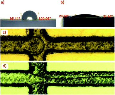
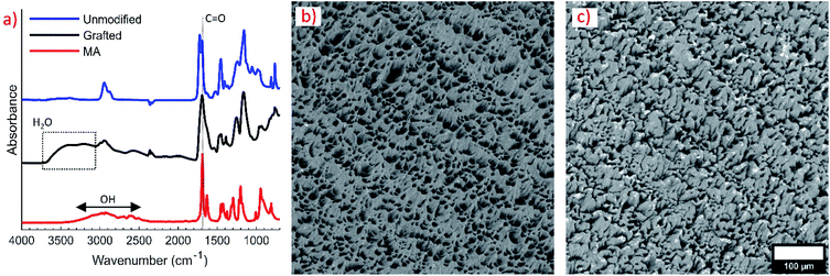
The wettability of unmodified and grafted surfaces of polymer parts was examined by sessile contact angle experiments with water droplets. Droplets had a contact angle of 97.0° ± 6.7° on the unmodified polymer surface, indicating a natively hydrophobic surface (Fig. 2a). Droplets had a contact angle of 25.4° ± 4.0° on the modified surface and did not wet out completely; however, regions around the droplet wet out onto the surface into small ridges of the 3D printed surface. Photographs of wetting behaviour on both surfaces are given in the ESI (Fig. S2).† The good water-wetting behavior was confirmed with flow experiments with water and butyl acetate. Butyl acetate droplets in DI water were easily formed with the graft-modified channels (Fig. 2c). In the unmodified device, butyl acetate wetted the channel walls and did not form any consistent droplets (Fig. 2d). Note that the darker appearance of the grafted device is a result of the 10 minute UV exposure.The presence of hydrophilic methacrylic acid groups on the surface of grafted polymer parts was confirmed by FTIR analysis, shown in Fig. 3a. The 1690 cm−1 peak characteristic of the methacrylic acid monomer C![[double bond, length as m-dash]](https://www.rsc.org/images/entities/char_e001.gif) O stretch is apparent on the grafted surface, overshadowing some of the adjacent peaks on the unmodified surface. A broad OH stretching from 2500–3300 cm−1 characteristic of the carboxylic acid group in methacrylic acid was also present on the part after grafting. A second bump up to 3800 cm−1 extending from the carboxylic acid OH stretch indicates the grafted layer is swelled with water. FTIR was taken shortly after the part was removed from DI water and blown dry with compressed air.
O stretch is apparent on the grafted surface, overshadowing some of the adjacent peaks on the unmodified surface. A broad OH stretching from 2500–3300 cm−1 characteristic of the carboxylic acid group in methacrylic acid was also present on the part after grafting. A second bump up to 3800 cm−1 extending from the carboxylic acid OH stretch indicates the grafted layer is swelled with water. FTIR was taken shortly after the part was removed from DI water and blown dry with compressed air.
SEM imaging was also used to verify surface modification. Grafted surfaces appeared smoother than the original unmodified surface. Fig. 3b shows the native polymer surface morphology without any treatment. The tendril-like features are rounded over in the grafted sample, depicted in Fig. 3c. The surface used for both figures was the top portion of a 3D printed coupon. For reference, the surfaces shown in Fig. 3b and c are the surfaces that the droplets were placed on in Fig. S2a and b in the ESI,† respectively.
Although the photografting method used is straightforward and can be done within an hour, techniques without deaeration of the grafting solution would eliminate the need for an inert gas cylinder, potentially making the technique more accessible. For example, Shuwen et al. modified a PDMS device with a grafting solution without deaeration to render it hydrophilic.39 The method utilized NaIO4 to scavenge dissolved oxygen from the grafting solution.40 Abate and colleagues used a similar method to selectively graft acrylic acid to a fluorinated sol–gel coating they coated a PDMS device with. Other grafting techniques used higher powered light sources to avoid deaerating the grafting solution.37,38,41 Tretinnikov et al. placed a quartz cover directly on their grafting solution placed on the part, creating a very small volume of solution and simultaneously preventing continuous oxygen diffusion into it.37 The cover eliminated the need for deoxygenation. This method was not practical for the application herein because it relies on thin films (on the order of tens of μm) of grafting solution isolated between a surface to be modified and an air-impenetrable quartz plate. With solution thicknesses above 100 μm, more oxygen was present in the placed solution, and the grafting yield drastically decreased to zero. Thus, the deeper channels in this work would not be successfully modified by directly applying the methods of Tretinnikov et al.37 A much higher intensity light (such as in the method of Jang and Go) may eliminate the need for deaeration, as the high-intensity light can overcome the negative effects of oxygen inhibition on the free-radical grafting mechanism.41 Our technique with deaeration of the grafting solution produces enough surface wettability for our device design and polymer choice, without the need for a higher powered light source than used herein (90 mW cm−2). An increase in radiation time may ensure adequate grafting if the method is adapted with a less powerful light source.
It has been shown that compared to other hydrophilic monomers, acrylic acid yields some of the most hydrophilic surfaces.39 We chose to use methacrylic acid because of its higher demonstrated grafting efficiency than acrylic acid.38 Moreover, the wettability of these surfaces may be further improved by treatment with NaOH.40 A range of other acrylate and methacrylate based monomer solutions could be substituted for the one herein if desired.
Design considerations
Two droplet generator designs (planar and concentric) were developed to be simple to assemble and print effectively on the 3D printer. Multiple copies of both designs could be printed within several hours on the 3D printer. The open-face design of the planar device (Fig. 4a) allows resin to drain sufficiently from the channels while printing. After sanding down the surface to remove layer-lines from 3D printing and polishing, a microscope slide clamped to the surface with binder clips results in a seal without leakage during droplet generation. Slight leakage was only observed around the edges of the device if fluids were forced through the devices. This leakage occurred during initial filling steps when flushing bubbles out of the devices, squeezing the syringes by hand. For the application herein, we did not need a clamping mechanism more robust than the binder clips. The syringe pumps stalled before any leakage occurred during droplet generation. For researchers interested in high pressure applications, an additional clamping fixture that can apply more pressure than a binder clip may be necessary.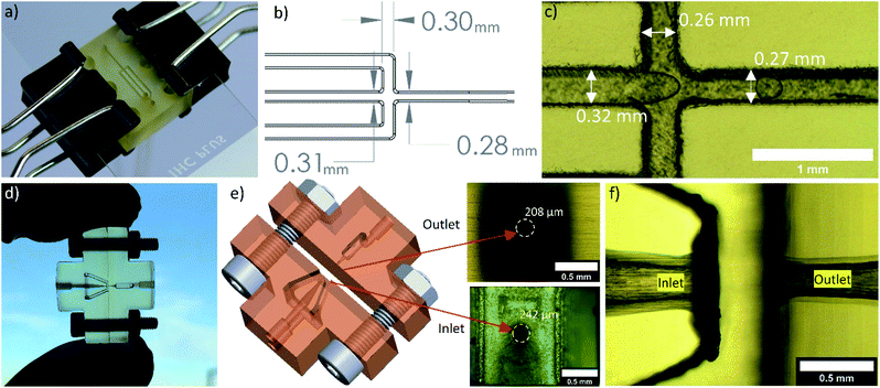 | ||
| Fig. 4 (a) Planar device clipped to a microscope slide. (b) Design dimensions of the top edges of the channels. The channels were engraved from the top sketch to a depth of 300 μm with a draft angle of 10°. (c) Measured dimensions on the printed chip. (d) Concentric droplet generator assembled prior to inserting tubing and clamping to a microscope slide. (e) 3D rendering of the concentric device and dimensions of the inlet and outlet orifice. The design diameter for both orifices was 250 μm. (f) Micrograph of the droplet generating region in a fully assembled concentric droplet generator. Additional photographs of the fully assembled devices are in the ESI (Fig. S3).† | ||
The concentric device was printed in two halves to effectively print the smallest features. Early prototypes were unsuccessful as one-piece prints. The small orifices printed successfully when they were parallel to the build direction. In this orientation, a one piece version of the design showed excessive distortion of the flat face perpendicular to the orifice. If the orifices were printed parallel to the build surface, the channels closed. Printing of a one-piece device may be feasible with custom 3D printers, resins, or high-end machines; however, this was not possible on the desktop printer with the current design. Thus, to enable 3D printing of small orifices, the device was split into two pieces such that the flat connecting portions were perfectly flat and perpendicular to the small orifices of each half.
We found the best away to assemble the concentric device (Fig. 4d) was to sand the two faces that are clamped together, treat the device by grafting, then clamp the device together. Then, the surface adjacent to the microscope slide was sanded after grafting to ensure the best contact. We did not need to smooth the surfaces further, but methods are available if needed. For example, van der Linden and colleagues used a drop of 3D printing resin to ensure a good seal between their devices and a holding fixture.24 They let the drop fill space between the chip and cover plate, then subjected the assembly to UV light.
The microscope slide assembly method yields a planar device with unobstructed viewing of droplet generation. Viewing of droplets in the concentric device is possible, but the 3D structure obscures some channels as they are surrounded by polymer. However, droplets can still be viewed through the channels. With good optical clarity of both devices, monitoring particle production is simple with an inverted microscope. In the event of contamination in the solutions, foreign particles disrupting the flow are easily identified. If particles become trapped in the channels or orifices, the microscope slide can simply be unclamped, and the channels purged to remove debris. Because of this feature, we did not find filtering solutions before use necessary for short-term experiments. Letting small particles settle from the polymer solutions and drawing solutions from the top surface was sufficient for most cases; however, filtering should be considered if using the devices for long periods of time so droplet production is uninterrupted.
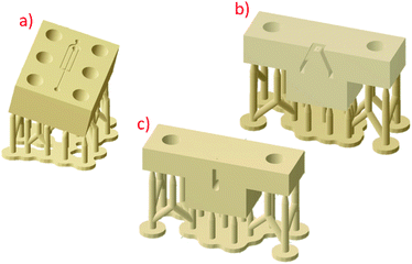
The design dimensions for both the planar device and concentric device compared well to the printed chips (Fig. 4b, c, e and f). From early prototypes, we found that a draft angle of 10° for the engraved planar channels helped with resin draining and printability. If the channels were not angled at the edges, some sides of the channels would be angled towards the inside of the channel, resulting in resin gelling in unwanted areas of the channel. If the open channels were printed parallel to the build platform, resin would not drain effectively from the features. We expect this effect to lessen with decreasing resin viscosity. For the resin used here, the angled print depicted in Fig. 1a produced the best channels and enabled effective draining of the resin. Design of the concentric device orifices was critical for the best prints. The inlet region was designed to gradually taper from a large diameter to the final orifice diameter. Preliminary designs with the taper extending to the orifice resulted in an orifice considerably larger than desired. A short constant diameter section before the orifice solved this dimensional issue.
Planar droplet generator
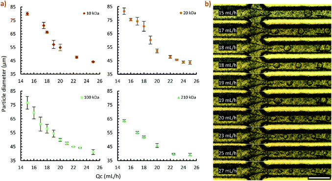
We used the planar droplet generator over a period of 5 months on a weekly basis. After use, channels were cleaned with ethyl acetate and water to remove traces of polystyrene and polyvinyl alcohol. Typically, the device was stored without purging remaining water and ethyl acetate from the channels. Retreatment of the surface was not needed during this period, suggesting the graft coating is robust over a long period of use and exposure to solvents.The capability of the planar droplet generator was demonstrated with several molecular weights of polystyrene solutions (Fig. 5a). In general, particle sizes achieved with high dispersed phase flowrates were highly repeatable. The higher error associated with lower flowrates is attributed to the flow being susceptible to disturbances. Fig. 5b shows the droplet flow regimes observed at a range of flowrates in the 100 kDa flow experiments. At continuous phase flowrates of 18 and 19 mL h−1, the flow was observed to occur in two meta-stable patterns. This is attributed to a transition from a dripping to jetting flow regime. Below 18 mL h−1 the droplets broke from the flow in the entrance of the outlet channel. At 25 mL h−1 and higher, the flow extended into the exit channel and droplets formed by jetting. By 27 mL h−1, the jet extended considerably into the channel. In the range studied, droplet size continued to decrease with increasing flowrate in the jetting regime.
In early trials, we used ethyl acetate as a solvent instead of butyl acetate. We found that with ethyl acetate, droplets could not be collected for long periods of time without the flow attaching to the microscope slide. This is attributed to the higher interfacial tension of butyl acetate with pure water (14.95 mN m−1) compared to ethyl acetate with pure water (7.37 mN m−1).42 Fluid contact with all walls is a drawback of planar devices. Thus, we also produced the concentric device to handle ethyl acetate solutions.
Concentric droplet generator
The concentric droplet generator effectively produced polystyrene particles in ethyl acetate for several hours without creeping of the dispersed phase further into the device. The production of several particle sizes was demonstrated (Fig. 6a) to evaluate the device. Representative images of the droplet breakup at each flowrate studied are shown in Fig. 6b. Uniform droplets were produced at low flowrates (4 and 6 mL h−1) where the droplet breakup occurred at the beginning of the exit orifice. At 8 mL h−1, the flow transitioned into a jetting regime. At this unstable condition, droplet breakup alternated from the beginning of the exit region to a distance down the channel. At 10 mL h−1, the flow appeared to be stable, however, the droplets were visibly less uniform than the lower flowrate cases. A detailed characterization of flow regimes and achievable size ranges is outside the scope of this work.In our device, we were unable to produce ethyl acetate in water droplets without surface modification. Fig. 6c shows the ethyl acetate (left) and water (right) interface just before entering the junction. Upon exiting the orifice, ethyl acetate rapidly wetted the face of the exit region and flowed into the exit orifice by wetting the device walls (Fig. 6d). With surface modification, ethyl acetate droplets could be formed in water without any surfactant (Fig. 6e). Similarly, we show that the unmodified concentric device can produce w/o emulsions without surface treatment (Fig. 6f).
Some researchers have demonstrated the ability to create droplets without surface treatment. Zhang et al. created a device via micro 3D printing where the tip of the dispersed phase orifice extended into the channel where breakup occurred.11 Although effective, the lack of surface treatment results in droplets wetting onto the tip of the nozzle. This may be problematic with a dispersed phase containing a polymer as any droplets that stick to the walls of the device have the potential to solidify, leading to device fouling. Refining our design with an extended conical orifice to inject polymer solution into the exit channel may enable droplet production without grafting; however, the fouling issue with handling polymer solutions remains. The small features required by this design change are also not favourable for desktop 3D printers.
An earlier device reported by Zhang et al. also utilized a 3D junction to generate droplets.15 They were able to produce droplets without surface modification in an arrangement similar to our concentric device. They used silicone oil as the dispersed phase, noting that if the oil wet the channel walls droplets could no longer be formed. Other fluids with even greater tendency to wet the surface may not be suitable for droplet generation in their device. We suspect that without surface modification in their device, polymer solution droplets would be difficult to reliably produce due to wetting and fouling issues.
Polystyrene particles
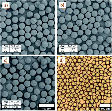
The ability to target particles of a specific size was demonstrated with the planar device and several molecular weights of polystyrene. The morphology of 10, 20, and 100 kDa polystyrene particles of similar sizes were analyzed by SEM imaging. Imaging of the particles (Fig. 7a–c) shows that the particles are highly spherical with low dispersity, but have some defects on the surface. Surface pitting was evident across all samples, as shown in SEM images and optical images (Fig. 7d). A large pit and several smaller pits were present on the surface of most particles. This is a consequence of the phase separation that occurs during drying. As solvent diffuses from the polystyrene–solvent droplets, water also diffuses into the droplets. This causes solvent and water to phase separate from the polystyrene rich phase. The solvent–water phase is encapsulated in the droplets and eventually settles to the outer surface where it remains as the polystyrene phase loses enough solvent to solidify. Ono et al. discussed this process in detail as a function of both solvent concentration and polymer molecular weight.43 If the defects are undesired, higher molecular weights and higher concentrations of polystyrene were shown to help reduce the pitting effect.Conclusions
We present a simple method of surface modification and two droplet generator designs that were manufactured using a commercial desktop SLA printer and resin system. The surfaces of the polymeric devices were modified by grafting methacrylic acid onto the surface by UV photografting. The presence of a thin layer of grafted methacrylic acid was confirmed by SEM imaging, infrared spectroscopy, and contact angle experiments. This modification enables the conversion of natively hydrophobic polymer surfaces to become hydrophilic and enable the production of oil in water dispersions. This coating method is an addition to only a few other demonstrated methods of surface modification for 3D printed droplet generators, where the surfaces tend to be natively hydrophobic. We demonstrated the applicability of the coating in our droplet generator designs by producing a range of <100 μm polystyrene particles, and the ability to target a specific particle size with narrow size distributions across compositions.Conflicts of interest
There are no conflicts of interest to declare.Acknowledgements
We would like to acknowledge financial support of the U.S. Army Research Laboratory through Cooperative Agreement W911NF-19-2-0152. The views and conclusions contained in this document are those of the authors and should not be interpreted as representing the official policies, either expressed or implied, of the U.S. Army Research Laboratory or the U.S. government. The U.S. Government is authorized to reproduce and distribute reprints for Government purposes notwithstanding any copyright notation herein. The authors are grateful to Shankar Kharal and Anjana Khanal of the Haase Research Group for discussions on contact angle measurements and usage of their instrument.References
- N. Bhattacharjee, A. Urrios, S. Kang and A. Folch, Lab Chip, 2016, 16, 1720–1742 RSC.
- D. J. Guckenberger, T. E. de Groot, A. M. Wan, D. J. Beebe and E. W. Young, Lab Chip, 2015, 15, 2364–2378 RSC.
- V. Mehta and S. N. Rath, Bio-Des. Manuf., 2021, 4, 311–343 CrossRef.
- A. V. Nielsen, M. J. Beauchamp, G. P. Nordin and A. T. Woolley, Annu. Rev. Anal. Chem., 2020, 13, 45–65 CrossRef PubMed.
- L. Wang and M. Pumera, Trends Anal. Chem., 2021, 135, 116151 CrossRef CAS.
- M. Hashimoto, R. Langer and D. S. Kohane, Lab Chip, 2013, 13, 252–259 RSC.
- T. Femmer, A. Jans, R. Eswein, N. Anwar, M. Moeller, M. Wessling and A. J. C. Kuehne, ACS Appl. Mater. Interfaces, 2015, 7, 12635–12638 CrossRef CAS PubMed.
- Y. H. Hwang, T. Um, J. Hong, G. N. Ahn, J. Qiao, I. S. Kang, L. Qi, H. Lee and D. P. Kim, Adv. Mater. Technol., 2019, 4, 1900457 CrossRef CAS.
- S. Waheed, J. M. Cabot, N. P. Macdonald, T. Lewis, R. M. Guijt, B. Paull and M. C. Breadmore, Lab Chip, 2016, 16, 1993–2013 RSC.
- L. Shang, Y. Cheng and Y. Zhao, Chem. Rev., 2017, 117, 7964–8040 CrossRef CAS PubMed.
- J. Zhang, W. Xu, F. Xu, W. Lu, L. Hu, J. Zhou, C. Zhang and Z. Jiang, J. Food Eng., 2021, 290, 110212 CrossRef CAS.
- A. J. L. Morgan, L. Hidalgo San Jose, W. D. Jamieson, J. M. Wymant, B. Song, P. Stephens, D. A. Barrow and O. K. Castell, PLoS One, 2016, 11, e0152023 CrossRef PubMed.
- Q. Ji, J. M. Zhang, Y. Liu, X. Li, P. Lv, D. Jin and H. Duan, Sci. Rep., 2018, 8, 4791 CrossRef PubMed.
- T. Kanai and M. Tsuchiya, Chem. Eng. J., 2016, 290, 400–404 CrossRef CAS.
- J. M. Zhang, E. Q. Li, A. A. Aguirre-Pablo and S. T. Thoroddsen, RSC Adv., 2016, 6, 2793–2799 RSC.
- Y. Morimoto, M. Kiyosawa and S. Takeuchi, Sens. Actuators, B, 2018, 274, 491–500 CrossRef CAS.
- Y. Morimoto, W. H. Tan and S. Takeuchi, Biomed. Microdevices, 2009, 11, 369–377 CrossRef PubMed.
- R. Chen, X. Chen, X. Jin and X. Zhu, Polym. Chem., 2017, 8, 2953–2958 RSC.
- M. Mohamed, H. Kumar, Z. Wang, N. Martin, B. Mills and K. Kim, J. Manuf. Mater. Process., 2019, 3, 26 Search PubMed.
- S. Vijayan and M. Hashimoto, RSC Adv., 2019, 9, 2822–2828 RSC.
- J. M. Zhang, A. A. Aguirre-Pablo, E. Q. Li, U. Buttner and S. T. Thoroddsen, RSC Adv., 2016, 6, 81120–81129 RSC.
- Z. Zhou, T. Kong, H. Mkaouar, K. N. Salama and J. M. Zhang, Sens. Actuators, A, 2018, 280, 422–428 CrossRef CAS.
- H. V. Nguyen, H. Q. Nguyen, V. D. Nguyen and T. S. Seo, Sens. Actuators, B, 2019, 296, 126676 CrossRef CAS.
- P. J. E. M. van der Linden, A. M. Popov and D. Pontoni, Lab Chip, 2020, 20(22), 4128–4140 RSC.
- H. Gong, B. P. Bickham, A. T. Woolley and G. P. Nordin, Lab Chip, 2017, 17, 2899–2909 RSC.
- J. M. Zhang, Q. Ji, Y. Liu, J. Huang and H. Duan, Lab Chip, 2018, 18, 3393–3404 RSC.
- A. I. Shallan, P. Smejkal, M. Corban, R. M. Guijt and M. C. Breadmore, Anal. Chem., 2014, 86, 3124–3130 CrossRef CAS PubMed.
- K. Ohtani, M. Tsuchiya, H. Sugiyama, T. Katakura, M. Hayakawa and T. Kanai, J. Oleo Sci., 2014, 63, 93–96 CrossRef CAS PubMed.
- L. Brandhoff, S. v. d. Driesche, F. Lucklum and M. J. Vellekoop, Bio-MEMS and Medical Microdevices II, Proc. SPIE, Barcelona, Spain, 2015, vol. 9518 Search PubMed.
- X. Wang, X. Cai, Q. Guo, T. Zhang, B. Kobe and J. Yang, ChemComm, 2013, 49, 10064–10066 RSC.
- C. F. Carlborg, T. Haraldsson, K. Oberg, M. Malkoch and W. van der Wijngaart, Lab Chip, 2011, 11, 3136–3147 RSC.
- C. E. Hoyle and C. N. Bowman, Angew. Chem., Int. Ed. Engl., 2010, 49, 1540–1573 CrossRef CAS PubMed.
- G. Pardon, F. Saharil, J. M. Karlsson, O. Supekar, C. F. Carlborg, W. van der Wijngaart and T. Haraldsson, Microfluid. Nanofluid., 2014, 17, 773–779 CrossRef CAS.
- L. H. Sperling, Introduction to Physical Polymer Science, Wiley, Hoboken, New Jersey, 2006 Search PubMed.
- A. R. Abate, A. T. Krummel, D. Lee, M. Marquez, C. Holtze and D. A. Weitz, Lab Chip, 2008, 8, 2157–2160 RSC.
- G. Gonzalez, A. Chiappone, K. Dietliker, C. F. Pirri and I. Roppolo, Adv. Mater. Technol., 2020, 5, 2000374 CrossRef CAS.
- O. N. Tretinnikov, V. V. Pilipenko and L. K. Prikhodchenko, Polym. Sci., Ser. B, 2012, 54, 427–433 CrossRef CAS.
- G. Li, G. He, Y. Zheng, X. Wang and H. Wang, J. Appl. Polym. Sci., 2012, 123, 1951–1959 CrossRef CAS.
- S. Hu, X. Ren, M. Bachman, C. E. Sims, G. P. Li and N. Allbritton, Anal. Chem., 2002, 74, 4117–4123 CrossRef CAS PubMed.
- T. Richey, H. Iwata, H. Oowaki, E. Uchida, S. Matsuda and Y. Ikada, Biomaterials, 2000, 21, 1057–1065 CrossRef CAS PubMed.
- J. Jang and W.-S. Go, Fibers Polym., 2008, 9, 375–379 CrossRef CAS.
- M. Z. Shahid, M. R. Usman, M. S. Akram, S. Y. Khawaja and W. Afzal, J. Chem. Eng. Data, 2017, 62, 1198–1203 CrossRef CAS.
- T. Ono, M. Yamada, Y. Suzuki, T. Taniguchi and M. Seki, RSC Adv., 2014, 4, 13557–13564 RSC.
Footnote |
| † Electronic supplementary information (ESI) available. See DOI: 10.1039/d1ra03057d |
| This journal is © The Royal Society of Chemistry 2021 |

