 Open Access Article
Robust, flexible, and high-performance electromagnetic interference shielding films with long-lasting service
Licui Wanga,
Zhaoxin Xiea,
Yanhu Zhan *ab,
Xuehui Haoa,
Yanyan Menga,
Shi Weib,
Zhenming Chen*b and
Hesheng Xia
 *c
*c
aSchool of Materials Science and Engineering, Liaocheng University, Liaocheng, 252000, China. E-mail: zhanyanhu@lcu.edu.cn; zhanyanhu@163.com
bGuangxi Key Laboratory of Calcium Carbonate Resources Comprehensive Utilization, Hezhou University, Hezhou City, 542899, China. E-mail: chenzhenming2@163.com
cState Key Laboratory of Polymer Materials Engineering, Polymer Research Institute, Sichuan University, Chengdu 610065, China. E-mail: xiahs@scu.edu.cn
First published on 21st May 2021
Abstract
It is of great significance for electromagnetic interference (EMI) shielding materials to fulfill long-lasting service requirements. Here, waterborne polyurethane (WPU) was coated on the surface of a silver nanowire (AgNW) network with sputter-deposited nickel nanoparticles (NiNPs) by dip-coating technology to improve their durability. After five dip-coating cycles, a WPU layer nearly coated the whole surface of the hybrid papers, and only a fraction of the metal filler is bare. The resultant hybrid papers exhibit an electrical conductivity of ∼3500 S m−1, remnant magnetization of 0.03 emu g−1, saturation magnetization of 0.10 emu g−1, and coercivity of 256 Oe. On the one hand, the presence of the WPU coating does not affect the shielding effectiveness (SE) of the hybrid papers; on the other hand, the WPU coating enhances the ability to resist tape peeling. Moreover, the resultant hybrid papers still maintain the original SE value (∼80 dB), even after exposure to air for 5 months owing to the isolation effect of the WPU coating, implying long-lasting durability. The results confirm that the obtained hybrid papers can meet the requirements of practical applications.
Introduction
In recent times, electromagnetic interference (EMI) pollution has worsened worldwide owing to the rapid growth of wireless communication devices, especially the arrival of the 5G era.1–3 To eliminate EMI pollution, the design and fabrication of high-performance EMI shielding materials are of great significance.4,5 Compared with metal materials, conductive polymer composites (CPCs), consisting of polymers and conductive fillers, are the best candidates as EMI shielding materials because of their intrinsic properties, such as flexibility, easy processing, low cost, and anticorrosion.6–8 It is well known that the EMI shielding effectiveness (SE) of CPCs is strongly contingent on the type and topology of conductive fillers.9–13 Among conductive fillers, silver nanowires (AgNWs) are attractive to researchers because of their excellent electrical conductivity (6.3 × 10⁷ S m−1) and high aspect ratio, which is beneficial in constructing a conductive network at low concentration.14,15 To improve the performance of AgNWs and obtain excellent CPC-based EMI shielding materials, a conductive network with interconnected AgNWs was formed on the surface of polymer films by spraying16 and coating.17 Lee et al. found that AgNW/cellulose papers fabricated by the dip-coating method exhibited an electrical conductivity of 6751 S m−1 and EMI SE of ∼48.6 dB.18According to Fresnel's equation, the EMI SE of CPCs is inseparable from their electrical conductivity and the magnetic permeability.19 To enhance the electrical conductivity of the AgNW network on the surface of CPCs, subsequently improving their EMI SE, several methods, such as welding,20 mechanical pressing,21 and sintering,22 have been developed. For example, Liang et al. demonstrated that the SE value of AgNW films increases from 5 dB to 25 dB via UV-induced welding.23 Very recently, our groups reported a novel approach to simultaneously enhancing the magnetic and electrical conductivity of AgNW networks by magnetron sputtering technology, which is an efficient method to form metal films on a substrate.24 The SE of AgNW/cellulose paper with sputter-deposited nickel nanoparticles (NiNPs) is 1.13 times higher than that of the system without NiNPs because NiNPs endow hybrid films with superior electrical conductivity and magnetic properties.
Of note, it is of paramount importance to extend the service life of CPC-based EMI shielding materials under external mechanical deformations or air. Nevertheless, AgNWs and NiNPs were easily peeled from the polymer films because of weak adhesion. More importantly, bare AgNWs and NiNPs can unavoidably be oxidized or even corroded in the atmosphere. The above two cases result in degraded electrical conductivity and EMI SE for CPCs.22,25,26 Coating with polymers is an effective approach to address these two issues. For example, under the aegis of a polyurethane (PU) layer, no obvious EMI SE degradation was observed for AgNW/carbon fibre fabric after ultrasonic treatment or tape peeling.25 EMI SE of MXene/AgNW film was still 34.8 dB after peeling off cycles because AgNWs were partly embedded into a poly(vinyl alcohol) film.27 In our previous paper, 1H,1H,2H,2H-perfluorodecanethiol was employed to enhance the hydrophobicity of AgNW/cellulose papers with sputter-deposited NiNPs, but the resultant papers have a poor ability to resist tape peeling.24
Herein, robust, flexible, and high-performance EMI shielding films with long-lasting service were fabricated via a simple approach. NiNPs were first deposited on the surface of AgNW-coated cellulose filter paper by a magnetron sputter procedure, and then waterborne polyurethane was coated on the above film. To evaluate stable shielding performance, we measured the SE of the resultant films, which underwent a vigorous external environment, e.g., blending, peeling, and a strong alkali solution. The films were first exposed to air for 5 months, and then their SE is tested to assess their long-lasting service.
Experimental
Materials
Cellulose filter papers with a diameter of 7 cm (CFP, 0.42 g cm−3), hydrochloric acid (HCl), sodium hydroxide (NaOH), and sodium chloride (NaCl) were supplied by Sinopharm Chemical Reagent Co., Ltd. (China). Waterborne polyurethane solution (WPU, 40 wt%, AMS-2066) was supplied by Guangzhou Yumay Chemical Co., Ltd. (China). Silver nanowire solution with a concentration of 20 mg mL−1 (XFJ03, diameter: 50 ± 5 nm, length: 100–200 μm) was obtained from Nanjing XFNANO Materials Tech Co., Ltd. (China). A nickel target with a purity of 99.995% was purchased from ZhongNuo Advanced Material (Beijing) Technology Co., Ltd. (China).Fabrication of CFP/AgNW/NiNP/WPU hybrid papers
CFP/AgNW/NiNP (CSN) papers were fabricated according to our previous paper.24 In brief, AgNWs were covered on CFP with ∼0.2 mm thickness by dip-coating over 20 cycles. Subsequently, NiNPs were deposited on one surface of CFP/AgNW paper for 15 min by a magnetron sputtering apparatus to obtain the CSN papers with a diameter of 7 cm. The DC power, temperature, base, and working pressure were 50 W, 28 °C, 5.0 × 10⁻⁴ Pa, and 0.5 Pa, respectively, during the magnetron sputtering procedure.The resulting papers were dipped into 10 wt% WPU solution, which was obtained by diluting the original solution, for 3 s and then dried at 60 °C for 15 min. The above process was repeated until the desired cycles. The obtained hybrid papers were named CSNPUx, where x means the dip-coating cycles in WPU solution.
Characterization
A Zeiss Ultra 55 apparatus (Jena, Germany) was used to observe the morphology of CSNPU papers at an accelerating voltage of 3 kV. All specimens were sputter-coated with gold before SEM observation. X-ray energy dispersion spectroscopy (EDS, Oxford Instruments, coupled to SEM microscopy) was used to analyse the chemical composition of the CSNPU papers by applying a 9 kV acceleration voltage under an 8.5 mm working distance. A diffractometer (D8 Advanced, Bruker Co., Germany) was employed to record the X-ray diffraction (XRD) patterns of the CSNPU papers. The spectra were recorded in transmission mode with 2θ values ranging from 5° to 60° at 40 kV. A picometer (Keithley 2000) system was used to measure the electrical conductivity of the resultant papers. Magnetic properties were studied using a vibratory sample magnetometer (PPMS-9, Quantum Design, USA) at room temperature with an applied field of −10![[thin space (1/6-em)]](https://www.rsc.org/images/entities/char_2009.gif) 000 to 10
000 to 10![[thin space (1/6-em)]](https://www.rsc.org/images/entities/char_2009.gif) 000 Oe. A vector network analyzer (Agilent N5247A) was employed to analyse the EMI SE of the resultant papers in the X-band (8.2–12.4 GHz). The diameter and thickness of the measured samples were 13 mm and ∼0.2 mm, respectively.
000 Oe. A vector network analyzer (Agilent N5247A) was employed to analyse the EMI SE of the resultant papers in the X-band (8.2–12.4 GHz). The diameter and thickness of the measured samples were 13 mm and ∼0.2 mm, respectively.
Results and discussion
XRD analysis of CSNPU papers
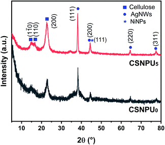
Fig. 1 displays XRD patterns of CSNPU0 and CSNPU5 papers. It is evident that no obvious discrepancy in the XRD patterns is observed before and after coating the WPU layers. All hybrid papers show the same characteristic diffraction peaks. The same diffraction peaks were located at 2θ = 38.2°, 44.4°, 64.5°, and 77.5°, assigned to the (111), (200), (220), and (311) fcc crystal planes of AgNWs, respectively, where the characteristic peaks at 2θ = 14.9°, 16.4° and 22.6° were attributed to the (1![[1 with combining macron]](https://www.rsc.org/images/entities/char_0031_0304.gif) 0), (110), and (200) planes of cellulose, respectively.28–30 Evidently, compared with the Ag (200) peak, the intensity of the Ag (111) peak is high, implying a polycrystalline structure with a strong Ag (111) preferred orientation, benefiting the construction of a perfect conductive network at a low concentration and enhancing the EMI SE of CPCs. It is hard to ignore that for all samples, the (111) peak of NiNPs at 2θ = 44.6° is so weak that it is covered by the strong peak of (200) of AgNWs at 2θ = 44.5° because the NiNP content is extremely low, as it was in our previous report.24 SEM images and EDS spectra of CSNPU papers are used to support the attendance of NiNPs in the next section.
0), (110), and (200) planes of cellulose, respectively.28–30 Evidently, compared with the Ag (200) peak, the intensity of the Ag (111) peak is high, implying a polycrystalline structure with a strong Ag (111) preferred orientation, benefiting the construction of a perfect conductive network at a low concentration and enhancing the EMI SE of CPCs. It is hard to ignore that for all samples, the (111) peak of NiNPs at 2θ = 44.6° is so weak that it is covered by the strong peak of (200) of AgNWs at 2θ = 44.5° because the NiNP content is extremely low, as it was in our previous report.24 SEM images and EDS spectra of CSNPU papers are used to support the attendance of NiNPs in the next section.
Morphology of CSNPU papers
The microstructure of CPCs strongly affects their properties,31 so the resulting CSNPU paper morphology was observed by SEM and is displayed in Fig. 2. It is easy to find the interconnected AgNW network at low magnification (Fig. 2a and a′). For the image with high magnification (Fig. 2a′′), the surface of AgNWs is no longer smooth and covered uniformly by some granulum, i.e., NiNPs, after the magnetron sputtering process. For CSNPU1 papers, some surfaces were coated by WPU (the region surrounded by red dots in Fig. 2b′), but most metal fillers were exposed (Fig. 2b and b′). At high magnification (Fig. 2b′′), the WPU layer embraces AgNWs with sputter-deposited NiNPs. In the case of CSNPU5 papers, WPU nearly coated the whole surface, and very few metal fillers were bare (Fig. 2c, c′ and c′′). The WPU layers, as protective clothing, enable the materials to resist vigorous external environments. Unfortunately, some microcracks can be found (Fig. 2c′′). Subsequently, EDS analysis was employed to further investigate the distribution of AgNWs and NiNPs. SEM images with elemental mapping and EDS spectra of CSNPU0 and CSNPU5 papers are summarized in Fig. 3. Elemental mappings for CSNPU0 papers, as shown in Fig. 3a, demonstrate that NiNPs are deposited on the surface of AgNWs and form a compact layer, which is helpful for enhancing the electrical conductivity of the AgNW conductive network. Notably, the uniform WPU coating does not affect the distribution of AgNWs and NiNPs, as shown in Fig. 3b. As expected, compared with CSNPU0 papers, the resultant CSNPU5 papers exhibit the C peak with remarkably strong intensity, confirming the presence of the WPU coating (Fig. 3c).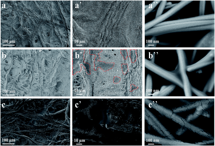 | ||
| Fig. 2 SEM images of CSNPU0 papers (a, a′ and a′′), CSNPU1 papers (b, b′ and b′′) and CSNPU5 papers (c, c′ and c′′). | ||
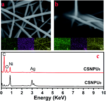 | ||
| Fig. 3 SEM image with elemental mappings of CSNPU0 (a), and CSNPU5 (b) papers; EDS spectra of CSNPU0, and CSNPU5 papers (c). | ||
Electrical conductivity and magnetic properties of CSNPU papers
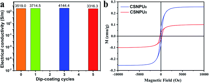
In general, excellent electrical conductivity, coupled with magnetic properties, would capacitate CPCs to exhibit outstanding EMI SE.19 The effect of the deposited mass of NiNPs on their electrical conductivity and magnetic properties was discussed in detail in a previous report.24 Here, we only research the effect of the WPU coating on the electrical conductivity and magnetic properties of CSNPU papers, as displayed in Fig. 4. Fig. 4a displays that the electrical conductivity of CSNPU0 papers reaches 3519.0 S m−1 and that the electrical conductivity of CSNPU papers is similar with that of CSNPU0 paper when the number of dip-coatings increases from 1 to 5, implying that the conductive network is too stable to be broken. Fig. 4b shows the typical S-shaped hysteresis loop for CSNPU papers. CSNPU5 papers have a remnant magnetization (Mr) of 0.03 emu g−1 and saturation magnetization (Ms) of 0.10 emu g−1, which are lower than those of CSNPU0 papers (Mr: 0.08 emu g−1; Ms: 0.26 emu g−1) and attributed to the attendance of a nonmagnetic WPU coating. In addition, the coercivity (Hc) of CSNPU0 and CSNPU5 papers are 182 Oe and 256 Oe, respectively.EMI SE of CSNPU papers
Fig. 5a presents the EMI SE of CSNPU papers in X-band at room temperature. It is worth noting that the EMI SEs of all CSNPU papers are independent of the frequency. Ultrahigh electrical conductivity, as well as good magnetic properties, endows CSNPU0 papers with excellent EMI SE (80.7 dB), better than that of the reported AgNW/poly(diallyldimethyl-ammonium chloride) films (31.3 dB).32 Remarkably, a nonobvious change in the SE value was found after dip-coating the WPU layer, as shown Fig. 5a. This is attributed to the AgNW network with sputter-deposited NiNPs being impregnable during the dip-coating process. In general, the EMI SE of CPCs is attributed to reflection mechanisms and absorption mechanisms. Reflection shielding (SER) and absorption shielding (SEA) are calculated by S parameters, and the total EMI SE (SET) is equal to the sum of SER and SEA.19 Fig. 5b displays that for all CSNPU papers, the SEA value is higher than the SER. For example, SET and SEA of CSNPU5 papers are 79.3 dB and 72.3 dB, respectively, while SER is only 7.0 dB. Compared with the reported Ag/polymer film (SET: 77.6 dB, SER: 13 dB),33 CSNPU5 papers exhibit a higher SET value and lower SER value, which is favor to decrease second pollution of EM wave. To investigate the shielding mechanisms, the power coefficients of transmissivity (T), absorption (A), and reflection (R) were calculated and are shown in Fig. 5c. For all CSNPU papers, the value of R is higher than that of A, which results from the impedance mismatch between air and hybrid papers. The result confirms that most of the initial power is reflected at the surface of the hybrid papers. From the EM energy point of view, therefore, the shielding mechanism of hybrid papers is reflection.27 In addition, it is interesting to note that SEA is greater than SER even for samples with high electrical conductivity and large reflectivity. The result can be explained by two reasons. The first is that SER is proportional to the logarithm of σ/μ (where σ and μ are the electrical conductivity and the magnetic permeability of shielding materials, respectively) according to Fresnel's equation.34 The presence of NiNPs not only enhances the electrical conductivity of hybrid papers but also improves their magnetic permeability. The increasing magnetic permeability partially drained the contribution of the increased electrical conductivity to the SER. The second is that SEA and SER were calculated by and SER = −10
![[thin space (1/6-em)]](https://www.rsc.org/images/entities/char_2009.gif) lg(1 − R) = −10
lg(1 − R) = −10![[thin space (1/6-em)]](https://www.rsc.org/images/entities/char_2009.gif) lg(A + T), respectively. The EM waves transmit through high electrically conductive shielding materials, so T/(A + T) is far less than (A + T), leading to SEA being higher than SER, and similar results were also reported by Kwon et al.35 For example, as shown in Fig. 5c, when an EM wave meets CSNPU5 papers, 79.8306825% of the incident power is first reflected (SER of 7.0 dB), 20.1693164% is absorbed (SEA of 72.3 dB), and only 0.0000011% can be transmitted.
lg(A + T), respectively. The EM waves transmit through high electrically conductive shielding materials, so T/(A + T) is far less than (A + T), leading to SEA being higher than SER, and similar results were also reported by Kwon et al.35 For example, as shown in Fig. 5c, when an EM wave meets CSNPU5 papers, 79.8306825% of the incident power is first reflected (SER of 7.0 dB), 20.1693164% is absorbed (SEA of 72.3 dB), and only 0.0000011% can be transmitted.
Durability of CSNPU based EMI papers
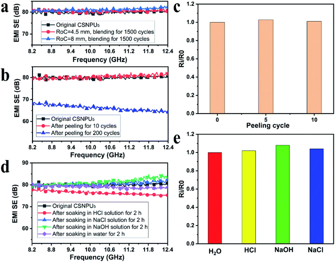
Satisfactory performance stability is a critical factor for evaluating the application value of CPC-based EMI shielding materials under harsh external environments, e.g., mechanical deformation, strong alkali and acid solutions, peeling off and long exposure to air.25,36–38 The bending stability of CSNPU5 paper was tested and is shown in Fig. 6a. Compared with the original samples, the CSNPU5 paper maintains a stable SE value after 1500 bending cycles at radii of curvature (RoCs) of 4.5 mm and 8 mm, indicating that the CSNPU5 paper is robust enough to resist blending deformation. Fig. 6b displays that the EMI SE of CSNPU5 paper remained at a high level of 80.6 dB after 10 tape-peeling cycles, attributable to the strong protection of WPU layers, leading to stable electrical conductivity (Fig. 6c). After 200 tape-peeling cycles, their SE decreases to 65.6 dB, which is still higher than that of the reported papers after the 100 peeling-cycles (Fig. 7) and far higher than the requirement of commercial EMI shielding materials (20 dB). Moreover, when immersed in NaOH solution (1 mol L−1), NaCl solution (1 mol L−1) and water for 2 h, CSNPU5 papers still show an EMI SE similar to that of the original sample (Fig. 6d), ascribed to these solutions not harming the perfect conductive network (Fig. 6e). However, after soaking HCl solution (1 mol L−1) for 2 h, the SE value of CSNPU5 papers slightly decreased, ascribed to NiNPs being dissolved by HCl.24 CSNPU5 papers were exposed to air for 5 months to assess their long-lasting durability. As shown in Fig. 8a, after 5 months, the SE value of CSNPU5 papers is ∼80 dB, implying long-lasting service. This is attributed to the fact that the AgNWs and NiNPs cannot be oxidized owing to the isolation effect of the WPU layer (Fig. 8b). Fig. 8c shows an SEM image of CSNPU5 paper that was exposed to air for 5 months. Except for the fact that some dust (the granule in Fig. 8c) adheres to the surface of the sample, its morphology is similar to that of the original samples (Fig. 2). Elemental mappings and EDS spectra of the exposed CSNPU5 paper further demonstrate that no obvious change in the chemical element is found, as shown in Fig. 8c and d. Elemental Si and Ca are attributed to the dust.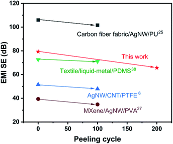 | ||
| Fig. 7 Comparison of SE of the resultant papers and the reported papers before and after peeling test. | ||
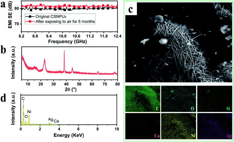 | ||
| Fig. 8 SE value (a), XRD pattern (b), SEM image with elemental mapping (c) and EDS spectra (d) of CSNPU5 paper after exposing to air for 5 months. | ||
Conclusions
In summary, we fabricated robust, flexible, and high-performance electromagnetic interference shielding films and investigated their morphology, electrical conductivity, magnetic properties, and durability in EMI shielding performance. Owing to the high electrical conductivity (∼3500 S m−1), the main shielding mechanism of CSNPU paper is a reflection mechanism. The WPU coatings could endure EMI shielding materials with high tolerance to harsh environments such as blending, tape peeling, and strong alkaline environments. Even after exposure to air for 5 months, the EMI SE of CSNPU5 papers remained consistent with the initial value (∼80 dB). These results confirm that the resultant CSNPU papers can meet the long-term service requirements of practical applications.Conflicts of interest
There are no conflicts to declare.Acknowledgements
This work was supported by the Natural Science Foundation of Shandong Province [ZR2019QEM009 and ZR2020QE026], International Cooperative Research Program between the National Natural Science Foundation of China and the Italian Ministry of Foreign Affairs [5171101504], and the Natural Science Foundation of Guangxi [2018GXNSFAA281218, 2020GXNSFBA297139].Notes and references
- Y. Zhan, Y. Cheng, N. Yan, Y. Li, Y. Meng, C. Zhang, Z. Chen and H. Xia, Chem. Eng. J., 2021, 417, 129339 CrossRef CAS.
- Y. Wang, K. Ren, J. Sun, W. Li, S. Zhao, Z. Chen and J. Guan, Compos. Sci. Technol., 2017, 140, 89–98 CrossRef CAS.
- Y. Zhan, E. Lago, C. Santillo, A. E. Del Río Castillo, S. Hao, G. G. Buonocore, Z. Chen, H. Xia, M. Lavorgna and F. Bonaccorso, Nanoscale, 2020, 12, 7782–7791 RSC.
- Y. Chen, L. Pang, Y. Li, H. Luo, G. Duan, C. Mei, W. Xu, W. Zhou, K. Liu and S. Jiang, Composites, Part A, 2020, 135, 105960 CrossRef CAS.
- E. Kim, D. Y. Lim, Y. Kang and E. Yoo, RSC Adv., 2016, 6, 52250–52254 RSC.
- L.-C. Jia, G. Zhang, L. Xu, W.-J. Sun, G.-J. Zhong, J. Lei, D.-X. Yan and Z.-M. Li, ACS Appl. Mater. Interfaces, 2019, 11, 1680–1688 CrossRef CAS PubMed.
- Y. Chen, L. Pang, Y. Li, H. Luo, G. Duan, C. Mei, W. Xu, W. Zhou, K. Liu and S. Jiang, Composites, Part A, 2020, 135, 105960 CrossRef CAS.
- F. Liu, Y. Li, S. Hao, Y. Cheng, Y. Zhan, C. Zhang, Y. Meng, Q. Xie and H. Xia, Carbohydr. Polym., 2020, 243, 116467 CrossRef CAS PubMed.
- L.-C. Jia, D.-X. Yan, Y. Yang, D. Zhou, C.-H. Cui, E. Bianco, J. Lou, R. Vajtai, B. Li, P. M. Ajayan and Z.-M. Li, Adv. Mater. Technol., 2017, 2, 1700078 CrossRef.
- X. Jin, J. Wang, L. Dai, X. Liu, L. Li, Y. Yang, Y. Cao, W. Wang, H. Wu and S. Guo, Chem. Eng. J., 2020, 380, 122475 CrossRef CAS.
- C. Song, X. Meng, H. Chen, Z. Liu, Q. Zhan, Y. Sun, W. Lu and Y. Dai, Compos. Commun., 2021, 100632 CrossRef.
- Y. Zhan, M. Oliviero, J. Wang, A. Sorrentino, G. G. Buonocore, L. Sorrentino, M. Lavorgna, H. Xia and S. Iannace, Nanoscale, 2019, 11, 1011–1020 RSC.
- Y. Zhan, Y. Meng and Q. Xie, J. Appl. Polym. Sci., 2021, 107995, 50597 CrossRef.
- Y. Wang, F.-Q. Gu, L.-J. Ni, K. Liang, K. Marcus, S.-L. Liu, F. Yang, J.-J. Chen and Z.-S. Feng, Nanoscale, 2017, 9, 18318–18325 RSC.
- W. H. Sun, D. S. Hung, T. T. Song and S. F. Lee, Ferroelectrics, 2012, 435, 148–154 CrossRef CAS.
- X. Zhang, Y. Zhong and Y. Yan, Phys. Status Solidi A, 2018, 215, 1800014 CrossRef.
- L.-C. Jia, D.-X. Yan, X. Liu, R. Ma, H.-Y. Wu and Z.-M. Li, ACS Appl. Mater. Interfaces, 2018, 10, 11941–11949 CrossRef CAS PubMed.
- T.-W. Lee, S.-E. Lee and Y. G. Jeong, ACS Appl. Mater. Interfaces, 2016, 8, 13123–13132 CrossRef CAS PubMed.
- Y. Zhan, J. Wang, K. Zhang, Y. Li, Y. Meng, N. Yan, W. Wei, F. Peng and H. Xia, Chem. Eng. J., 2018, 344, 184–193 CrossRef CAS.
- X. Liang, T. Zhao, W. Jiang, X. Yu, Y. Hu, P. Zhu, H. Zheng, R. Sun and C.-P. Wong, Nano Energy, 2019, 59, 508–516 CrossRef CAS.
- L. Hu, H. S. Kim, J.-Y. Lee, P. Peumans and Y. Cui, ACS Nano, 2010, 4, 2955–2963 CrossRef CAS PubMed.
- D. G. Kim, J. H. Choi, D.-K. Choi and S. W. Kim, ACS Appl. Mater. Interfaces, 2018, 10, 29730–29740 CrossRef CAS PubMed.
- X. Liang, J. Lu, T. Zhao, X. Yu, Q. Jiang, Y. Hu, P. Zhu, R. Sun and C.-P. Wong, Adv. Mater. Interfaces, 2018, 353, 1801635 CrossRef.
- Y. Zhan, X. Hao, L. Wang, X. Jiang, Y. Cheng, C. Wang, Y. Meng, H. Xia and Z. Chen, ACS Appl. Mater. Interfaces, 2021, 13, 14623–14633 CrossRef CAS PubMed.
- L.-C. Jia, L. Xu, F. Ren, P.-G. Ren, D.-X. Yan and Z.-M. Li, Carbon, 2019, 144, 101–108 CrossRef CAS.
- J.-H. Pu, X.-J. Zha, L.-S. Tang, L. Bai, R.-Y. Bao, Z.-Y. Liu, M.-B. Yang and W. Yang, ACS Appl. Mater. Interfaces, 2018, 10, 40880–40889 CrossRef CAS PubMed.
- B. Zhou, M. Su, D. Yang, G. Han, Y. Feng, B. Wang, J. Ma, J. Ma, C. Liu and C. Shen, ACS Appl. Mater. Interfaces, 2020, 12, 40859–40869 CrossRef PubMed.
- Z. Ma, S. Kang, J. Ma, L. Shao, Y. Zhang, C. Liu, A. Wei, X. Xiang, L. Wei and J. Gu, ACS Nano, 2020, 14, 8368–8382 CrossRef CAS PubMed.
- R. Ou, Y. Xie, X. Shen, F. Yuan, H. Wang and Q. Wang, J. Mater. Sci., 2012, 47, 5978–5986 CrossRef CAS.
- Y. Zhan, Y. Meng, W. Li, Z. Chen, N. Yan, Y. Li and M. Teng, Ind. Crops Prod., 2018, 122, 422–429 CrossRef CAS.
- Y. Zhan, S. Hao, Y. Li, C. Santillo, C. Zhang, L. Sorrentino, M. Lavorgna, H. Xia and Z. Chen, Compos. Sci. Technol., 2021, 205, 108689 CrossRef CAS.
- X. Zhu, J. Xu, F. Qin, Z. Yan, A. Guo and C. Kan, Nanoscale, 2020, 12, 14589–14597 RSC.
- Z. Zeng, F. Jiang, Y. Yue, D. Han, L. Lin, S. Zhao, Y.-B. Zhao, Z. Pan, C. Li, G. Nyström and J. Wang, Adv. Mater., 2020, 32, 1908496 CrossRef CAS PubMed.
- Y.-J. Wan, X.-Y. Wang, X.-M. Li, S.-Y. Liao, Z.-Q. Lin, Y.-G. Hu, T. Zhao, X.-L. Zeng, C.-H. Li, S.-H. Yu, P.-L. Zhu, R. Sun and C.-P. Wong, ACS Nano, 2020, 14, 14134–14145 CrossRef CAS PubMed.
- S. Kwon, R. Ma, U. Kim, H. R. Choi and S. Baik, Carbon, 2014, 68, 118–124 CrossRef CAS.
- L.-X. Liu, W. Chen, H.-B. Zhang, Q.-W. Wang, F. Guan and Z.-Z. Yu, Adv. Funct. Mater., 2019, 29, 1905197 CrossRef CAS.
- Y. Zhou, Z. Sun, L. Jiang, S. Chen, J. Ma and F. Zhou, Appl. Surf. Sci., 2020, 533, 147431 CrossRef CAS.
- L.-C. Jia, X.-X. Jia, W.-J. Sun, Y.-P. Zhang, L. Xu, D.-X. Yan, H.-J. Su and Z.-M. Li, ACS Appl. Mater. Interfaces, 2020, 12, 53230–53238 CrossRef CAS PubMed.
| This journal is © The Royal Society of Chemistry 2021 |

