 Open Access Article
A structured catalyst with high dispersity of Au species based on hollow SiC foam with porous walls for acetylene hydrochlorination†
Peng Wangab,
Xiaodan Yangb,
Ye Zhangab,
Yong Gaob and
Jinsong Zhang *b
*b
aSchool of Materials Science and Engineering, Northeastern University, Shenyang 110819, Liaoning, China
bShenyang National Laboratory for Materials Science, Institute of Metal Research, Chinese Academy of Sciences, Shenyang 110016, Liaoning, China. E-mail: jszhang@imr.ac.cn
First published on 2nd June 2021
Abstract
It is essential to improve the catalytic stability of Au-based catalysts for acetylene hydrochlorination. In this study, a novel hollow SiC foam with porous walls (HSFp) is proposed to modify the Au catalyst distribution on the foam-based structured catalyst. The scanning electron microscopy and 3D X-ray tomography results showed that the hollow structure and the porous ceramic wall of HSFp were successfully obtained. An Au/AC/HSF structured catalyst was prepared by the slurry-coating and impregnation method. Then the effects of the wall pore structure of HSFp on the distribution of Au species and the stability of the catalyst were studied by comparison with a hollow SiC foam with compact walls (HSFc). The HSFp with 3D interconnected hollow channel structure was demonstrated to have a promotion effect on the reaction stability due to its ability to refine the catalyst particles during the impregnation and drying processes. The result indicates that the time on stream of acetylene conversion above 90% over the Au/AC/HSFp structured catalyst reaches about 380 h at an acetylene gaseous hourly space velocity of 130 h−1, which is much longer than that of the Au/AC/HSFc. In addition, a bidirectional diffusion effect that can enhance the catalyst distribution by the porous wall of HSF was proposed in this paper. This may have positive significance in the field of preparation of structured catalysts.
Introduction
Hydrochlorination of acetylene on HgCl2 to the vinyl chloride monomer (VCM) used for the synthesis of polyvinyl chloride (PVC), is the dominant industrial route in the coal-rich regions of China.1–4 However, HgCl2 is highly toxic and volatile so it is very much necessary and urgent to explore alternative green catalysts for acetylene hydrochlorination.5–7 AuCl3 has attracted special attention among possible alternatives because of its highest catalytic activity.8,9 However, its high cost and poor stability limit its application.10,11 Thus, increasing the durability of Au/AC is an important issue.12,13Hydrochlorination of acetylene is an exothermic reaction, and the high heat released easily leads to catalyst deactivation caused by the sintering of gold clusters into particles and the formation of carbonaceous deposits.14,15 In our previous work,16 compared to the Au/AC particulate catalysts, SiC foam supporting Au/AC catalyst exhibits superior activity and stability in acetylene hydrochlorination, due to the enhancement of mass and heat transfer. However, the deposited AuCl3 with a conventional impregnation method easily redistribute caused by the capillary forces and thus accumulate at the monolith's outer surface during drying process.17 Nowadays, microwave drying, drying in a forced airflow, and freeze-drying can reduce the maldistribution of active component by preventing solution movement in the pores during the drying step.18–20 However, the first two kind of methods become powerless for larger-sized monoliths due to the enlarging distance for the solvent evaporation. The major disadvantage of the freeze-drying procedure is that it is more expensive than the other drying methods. Therefore, looking for a new way to improve the distribution of active component is worthy and necessary.
In recent years, hollow materials with an asymmetric pore structure and an extremely high ratio of the surface area to volume, have shown potential applications as membrane reactors, membrane contactors, and membrane distributor in heterogeneous catalytic reaction.21–23 Inspired by this, a novel hollow SiC foam with porous wall (HSFp) was prepared in our laboratory and applied as catalyst support based on an assumption that the bidirectional diffusion of solvent may achieve during the drying process of wet-impregnated structured catalysts, thus shortening the evaporation distance of solvent and improving the distribution of active component. In order to determine this assumption, HSF with compact wall (HSFc) was also prepared and used for experiment to compare its catalytic performance with HSFp.
This study aims at proposing two structured supports (HSFc and HSFp) to load Au/AC catalysts via the same preparation process and comparing the catalytic performance of the two structured catalysts for acetylene hydrochlorination in a fixed bed reactor at the same reaction conditions. A series of structural and physicochemical characterization was carried out to analyze their differences. Furthermore, the influencing mechanism of the distribution of Au active component by the two structured supports was also discussed.
Experimental
Synthesis of HSF
The HSFs in cylinder shape (39 mm outer diameter, 4 mm inner diameter and 50 mm height) and with an average pore size of about 3.5 mm, prepared by polymer pyrolysis combined with melt silicon reactive sintering method in our laboratory,24 were used as the supports to prepare the structured catalyst. The detail of synthetic procedure of SiC ceramic foam was reported in our previous work.25 Moreover, the hollow structure of SiC foam was obtained by removing the plastic foam template by special process. The ceramic wall of HSFs can be prepared into compact or porous through changing the component of slurry. The open porosity of HSF was controlled as about 75% to ensure the loading of carbon coating. Prior to be used as structured support, the HSF was treated with boiling NaOH solution (10 mol L−1) to remove the residual silicon on the strut surface. Finally, the HSF was ultrasonically cleaned with deionized water three times and dried at 120 °C for 4 h.Preparation of the activated carbon coating
At first, commercial activated carbon pellets were crushed and ball-milled to obtain fine activated carbon powder. The coating slurry was then prepared by ball-milling the obtained fine activated carbon powder and liquid amino phenolic resin (brought from Beijing Composite Materials Co., Ltd, China) in ethanol. Secondly, the HSF was coated with the slurry and dried at 180 °C repeatedly until the mass increment reached about 10 g (weighing after every desiccation and the relation between coating mass and washcoating times was shown in Fig. S1†). Afterwards, the composite was pyrolyzed in the process of heating to 830 °C under high purity nitrogen and activated for 50 min under CO2 with a flowing rate of 200 mL min−1. The structured support (denoted as AC/HSF) was obtained after pyrolysis and activation, and the residual mass of activated carbon coating was about 4.5 g.Au loading on AC/HSF support
To improve the wettability of activated carbon for efficient adsorption of AuCl3 in aqueous solution, the AC/HSF (59 mL) was impregnated in 1 mol L−1 nitric acid solution at 100 °C for 20 min, and then was immersed in a water solution of 0.1 g HAuCl4·4H2O (200 mL). The mixed solution was heated to be boiling so that the AuCl3 was completely adsorbed. The structured catalyst (denoted as Au/AC/HSF) was then obtained after evaporation at 85 °C for 4 h. Therefore, the final loading of Au is 1.06 wt% based on activated carbon (0.81 mg per mL based on the structured catalyst volume), determined by Inductively Coupled Plasma Optical Emission Spectrometer (ICP-OES).Hydrochlorination of acetylene
The hydrochlorination of acetylene was carried out in a fixed bed stainless steel reactor of 41 mm inner diameter (as shown in Fig. S2†). In the catalytic tests, the prepared Au/AC/HSF was placed in the isothermal region of the reactor, and it was wrapped with graphite paper to fill the gap between it and the tube wall. Hydrogen chloride and acetylene were regulated by calibrated mass flow controller and fed into the reactor after passing through the drying tube, respectively. Before the reaction, the reactor was purged with high purity nitrogen to remove water vapor and air in the system. After the catalyst was activated by a certain flowing rate of HCl for 2 h, HCl (140 mL min−1) and C2H2 (127 mL min−1) with the molar ratio of 1.1 were fed into the reactor, leading to acetylene gaseous hourly space velocity (GHSV) of 130 h−1. The temperature of the reactor was initially set as 170 °C, and the pressure of the system was kept at 0.05–0.06 MPa. The compositions of products were analyzed by gas chromatography (HP 7890A with FID detection, HP-AL/S) after the gas mixture was passed through a tetrafluoroethylene bottle filled with NaOH solution to get rid of the excess HCl. A typical GC spectrum is shown in Fig. S3.†Characterization
The three-dimensional morphology of HSF was characterized by 3D X-ray tomography (XRT). The sample was scanned with 160 kV maximum X-ray energy at the maximum pixel resolution of 1.0 μm. The sample was rotated through 360° about the axis of rotary table, so that the X-rays were able to penetrate the sample from all directions. X-ray diffraction (XRD) data was collected on a Rigaku D/MAX-2500 X-ray diffractometer using Cu Kα radiation at a scanning rate of 10° min−1.The pore size distribution of HSF was characterized by mercury intrusion porosimetry (Micromeritics AutoPore IV 9500). The specific surface area, pore volume and average pore size of the catalysts were measured using N2 adsorption–desorption measurements at 77 K by using a Micromeritics 3Flex surface characterization analyzer. The specific surface area (SBET) of the catalysts was calculated from the nitrogen isotherm by the BET method. The average pore size (DBJH) and the pore volume (VBJH) were calculated by the BJH method.
The microstructures of the samples were detected by a field emission scanning electron microscope (SUPRA 35, SEM). The distribution of elements in the structured catalyst was measured by an energy dispersive X-ray spectroscopy (Oxford/Inca, EDS). The resin was used as filler material to prepare resin-coated structured catalysts samples for processing coating cross-section samples. The morphologies of the samples were observed by an FEI Tecnai T12 transmission electron microscope (TEM). The catalysts were removed from the HSF, and then ultrasonically dispersed in ethanol. The upper supernatant was supported on the carbon-film-coated copper grids before characterization by TEM.
X-ray photoelectron spectroscopy (XPS) was carried out on a VG Scientific ESCALAB 250 spectrometer equipped with an Al Kα X-ray source (1486.6 eV), and all the binding energies were referenced to the C 1s peak at 284.6 eV from the adventitious carbon.
Results and discussion
Characterization of HSF and AC/HSF
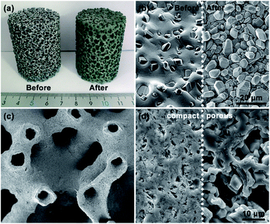
An optical photograph of the HSF is shown in Fig. 1a. The color of the SiC foam changed from silver to green after removing the residual Si by boiling NaOH solution. The micrograph of the HSF strut surface before and after being treated with NaOH is displayed in Fig. 1b. The residual Si was removed from the HSF strut surface after pretreatment, and a rough surface composed of SiC grains was exposed. The coarse surface is beneficial to the preparation of carbon coating, and the adhesive strength between carbon coating and foam strut can be enhanced. The hollow structure inner the HSF can be seen directly from Fig. 1c. However, the hollow channels are not open, which can avoid the AC coating entering the cavity of the HSF strut during the loading process. The average diameter of hollow cavity and the average thickness of the SiC wall were about 0.5 mm and 0.2 mm, respectively. As shown in Fig. 1d, the section of HSFc has almost no pores, while the section of HSFp has a large number of pores at the same magnification. Besides, it can be seen that the pores in the porous wall have a clear stereoscopic sense, indicating that the channels inside and outside the foam skeleton are connected.XRT was used to characterize the three-dimensional structure of a typical HSFp, and the results are rendered in Fig. 2. Each section of the whole sample was imaged with detector and optical magnification as it offered the best trade-off between resolution, field of view and contrast sufficient to distinguish different materials.26 Fig. 2a indicates the actual 3D morphology of the foam material, and the yellow region is completely composed of SiC particles. Fig. 2b shows the pores inner SiC skeleton, and it can be seen that the pores are dispersed distribution, which is obtained by the special treatment during material preparation process. Two kinds of hollow foam with compact ceramic wall and porous ceramic wall can be manufactured by regulating the pore in SiC struts. The overall diagram of the SiC skeleton and the hollow cavity is shown in Fig. 2c, where the red region represents the hollow cavity. Fig. 2d displays the morphology of the hollow cavity, indicating that the inner channel is an integrated state of 3D connectivity. The porous wall of HSFp was further characterized by mercury intrusion porosimetry method and the pore size distribution is presented in Fig. S4.† This clearly indicates that the wall of HSFp possesses a large number of macropores with pore sizes ranging from 150 to 2000 nm. It is evident that the hollow cavity of HSFp and the outside are interconnected through the porous wall. These results prove that the HSFp has been successfully prepared, and the novel hollow structure combined with the porous ceramic wall may affect the performance of structured catalysts.
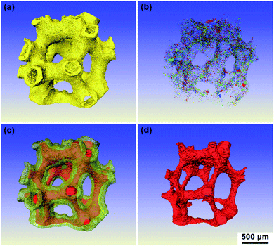 | ||
| Fig. 2 3D images of a typical HSFp produced by XRT: (a) SiC, (b) pores of SiC wall, (c) SiC and hollow cavity and (d) hollow cavity. | ||
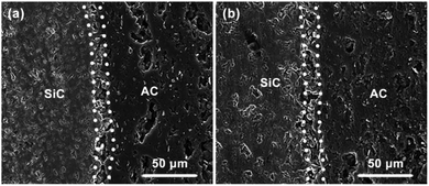
The cross-section of AC/HSF was observed by SEM and the images are displayed in Fig. 3. As shown in the figure, a porous layer of the carbon coating on the HSF was obtained after the activation. A good adhesion between the foam strut and the carbon coating was observed and there was no stratification or gap in the radial direction of the coating. The sufficient bonding strength is a prerequisite for long-term use of structured catalysts. Activated carbon coatings on the two kinds of HSFs have no obvious difference in character, excepting that the activated carbon near the SiC side of the HSFc has some larger pores. It is likely that the HSFp has a positive effect on the volatilization of volatile substance during the pyrolysis process, and then changes the pore formation of activated carbon during the activation process.
N2 adsorption–desorption experiments were carried out to study the textural properties of different AC/HSF structured supports. The N2 adsorption–desorption isotherms and the pore size distribution of the AC/HSFc and AC/HSFp are shown in Fig. 4. Both the isotherms belong to well-defined type IV with the hysteresis loop characteristic of the mesoporous structure. The corresponding texture parameters are presented in Table 1. The SBET of AC/HSFc and AC/HSFp is 47.04 m2 g−1 and 55.57 m2 g−1, respectively. Compared with the specific surface area of HSF (about 0.4 m2 g−1),27 the structured supports have the ability to provide a good loading environment for the Au catalysts. The SBET of AC/HSFp is higher than that of AC/HSFc, while the pore diameter is lower, indicating that the pores of AC/HSFp are more and it is helpful to the dispersity of Au catalysts. It can be explained that the porous wall of HSF has a positive effect on the pore formation of activated carbon during the activation process.
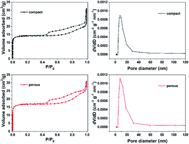 | ||
| Fig. 4 N2 adsorption–desorption isotherms and the pore size distribution for the AC/HSF structured supports. | ||
| Samples | SBET (m2 g−1) | VBJH (cm3 g−1) | DBJH (nm) |
|---|---|---|---|
| AC/HSFc | 47.04 | 0.028 | 4.06 |
| AC/HSFp | 55.57 | 0.025 | 3.44 |
Catalytic performance for acetylene hydrochlorination
Fig. 5 shows the acetylene conversion of structured catalysts with different structured support as a function of reaction time. It is clear that the catalytic activity of the two structured catalysts rapidly reaches about 100% within a few hours, and the activity of Au/AC/HSFp structured catalyst is slightly higher than that of Au/AC/HSFc. Subsequently, both structured catalysts showed excellent stability, and the catalytic activity decreased slowly with the reaction time. In particular, Au/AC/HSFp structured catalyst decreased to 90% after 380 hours of conversion, compared to 200 h of Au/AC/HSFc structured catalyst. It should be emphasized that for all the tests conducted in the current study, the selectivity to VCM was above 99.8% with trace amounts (<0.2%) of 1,2-dichloroethane and chlorinated oligomers during the entire operating period (Fig. S5†).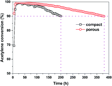 | ||
| Fig. 5 Acetylene conversion of structured catalysts with different structured support as a function of reaction time. Reaction conditions: T = 170 °C, GHSV (C2H2) = 130 h−1 and HCl/C2H2 = 1.1. | ||
Characterization of catalysts
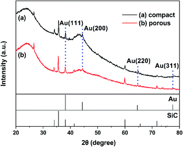
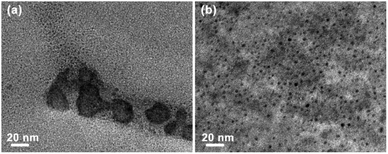
Fig. 6 illustrates the XRD patterns of the fresh Au/AC/HSFc and Au/AC/HSFp structured catalysts. There is a diffraction peak at 2θ = 26.64° that is the strongest characteristic peak of quartz, a common contaminant in many activated carbons. Therefore, the peak at 26.64° in the sample is assigned to quartz in the activated carbon.28 Two broad peaks take place near 25.48° and 42.80° in two patterns are corresponded to the (002) and (100) planes of carbon,29 while the peaks at 34.09°, 35.60°, 38.13°, 41.40°, 59.98° and 71.78° were assigned to the characteristic peaks of SiC.24 The presence of SiC is attributed to the fact that the Au/AC powder used for XRD characterization was stripped from the structured catalyst as a whole. Moreover, the weak Au diffraction peaks were detected at 38.18°, 44.40°, 64.58° and 77.55°, corresponding to the diffractions of (111), (200), (220) and (311) lattice planes (JCPDS no. 02-1095). It may probably be attributed to the slight reduction by activated carbon during the preparation and storage.30 According to the XRD results, the chemical components of the two fresh Au/AC/HSF structured catalysts are similar and have no obvious difference in catalytic performance.Fig. 7 shows the TEM micrographs of the fresh Au/AC/HSF structured catalysts. It was observed that the average size of Au particles of the two catalysts was similar. However, the Au species of Au/AC/HSFc showed an obvious aggregation phenomenon compared with Au/AC/HSFp. It is possible that more deactivation could have been caused by sintering of the Au nanoparticles, because the irreversible aggregation is the principal reason for catalyst deactivation during the chemical reaction.15,31 The Au species are uniformly distributed on the AC/HSFp, which is particularly important for improving the performance of the catalysts. The above discussion demonstrates that the use of HSFp may significantly inhibit the reduction of Au species and the continuous growth of Au particles, thus enhancing the stability of the structured catalyst.10
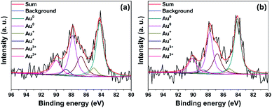
XPS analysis was used to detect the valence state and relative content of gold species on the surface of the fresh structured catalysts. The detailed fitting analysis shows that there are two peaks, corresponding to 4f7/2 and 4f5/2 spin orbit states, for each valence state of gold species. The deconvolution results in Table 2 and Fig. 8 indicate that the Au 4f7/2 peaks at 84.1, 85.1 and 86.8 eV, and the Au 4f5/2 peaks at 87.8, 88.7 and 90.1 eV are assigned to Au0, Au+ and Au3+ species, respectively.32,33 As shown in Fig. 8, the fresh Au/AC/HSF catalyst consists of gold species in the form of Au0, Au+ and Au3+. Simultaneously, the content of Au0 species on the Au/AC/HSFc and the Au/AC/HSFp catalyst is 60.4% and 62.8%, respectively. There are more Au0 species in the Au/AC/HSFp catalyst, indicating a relatively high degree of Au3+ reduction by activated carbon during the preparation of the catalyst. More Au3+ species are reduced to the low valence Au0, implying more contact sites for Au3+ species and activated carbon. Moreover, this may be another evidence of the better dispersity of Au species in Au/AC/HSFp structured catalyst.
| Catalyst | Au species (area%) | Binding energies (eV) | |||||||
|---|---|---|---|---|---|---|---|---|---|
| Au3+ | Au+ | Au0 | Au3+ | Au+ | Au0 | ||||
| 4f7/2 | 4f5/2 | 4f7/2 | 4f5/2 | 4f7/2 | 4f5/2 | ||||
| Au/AC/HSFc | 29.5 | 10.1 | 60.4 | 86.7 | 90.0 | 85.0 | 88.7 | 84.2 | 87.8 |
| Au/AC/HSFp | 29.8 | 7.4 | 62.8 | 86.8 | 90.1 | 85.1 | 88.7 | 84.1 | 87.8 |
In order to further confirm the difference of catalyst distribution between the two kinds of structured catalysts, the back-scattered electron (BSE) images and the radial distribution of Au elements on the carbon coating of cross-section of used Au/AC/HSF structured catalyst was determined by SEM-EDS line scanning and displayed in Fig. 9 (the magnified BSE images are shown in Fig. S6†). The Au particle distribution of used structured catalysts can reflect the distribution of active sites in fresh structured catalysts because the catalyst deactivation occurs in situ. As can be seen from Fig. 9a and b, the activated carbon coating on the Au/AC/HSFc is rather porous, but the shining Au element can only be found within a depth of about 80 μm from the surface. Seeing more closely to the outer part of the carbon coating, as shown in Fig. S6c,† the Au particles are most intensely dispersed in the thickness of about 40 μm and the particle size is larger than that of the inner part. By contrast, as shown in Fig. 9c, d and S6d,† the distribution of gold particles on the Au/AC/HSFp is very uniform, and the particle size is smaller than that of Au/AC/HSFc. So the Au/AC/HSFp has the higher catalytic performance after using for the same reaction time. It indicated that the HSFp made the prepared catalyst had better distribution and inhibited the deactivation of the catalyst during the reaction.
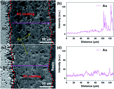 | ||
| Fig. 9 Back-scattered electron images and Au distribution of the cross-section of used Au/AC/HSF structured catalysts. (a and b) Compact and (c and d) porous. | ||
There are two main reasons for the deactivation of Au-based catalysts: (1) reduction of cationic Au species (Au3+ and Au+) to metallic Au0 species in the presence of an electron-rich substrate (such as C2H2), aggregation of Au0 species or Au nanoparticles because of the high surface energy; (2) the carbonaceous deposited on the surface of catalyst covers the active sites.31,34,35 On the one hand, as evidenced by the TEM and SEM images (Fig. 7 and 9), the distribution of active sites on the Au/AC/HSFp is better, and the particle size is smaller than that of Au/AC/HSFc. The better dispersion of Au species of Au/AC/HSFp, means that the interaction between the active components and the activated carbon support is stronger, which can inhibit the sintering and agglomeration process of the Au catalyst through the carrier effect.36,37 On the other hand, the uniform dispersion of Au species reduces the number of active sites on the catalyst surface and reduces the particle size, thus reducing the formation of carbonaceous deposits on the catalyst surface.38 As seen in Fig. S7,† the Au species covered by carbonaceous on the used Au/AC/HSFp catalyst after 380 h reaction are less than that of the used Au/AC/HSFc catalyst after 200 h reaction, indicating that the deactivation effect caused by carbonaceous accumulation of Au/AC/HSFp under the same conditions is lower. Moreover, for structured catalyst, the stability is also related to its activity. The active components with better distribution and smaller particle size have higher catalytic activity,34 so the conversion near 100% in per unit time only requires fewer catalysts to participate in the reaction. This may also be one of the reasons for the longer lifetime of the Au/AC/SHFp structured catalyst. In conclusion, we believe that the Au/AC/HSFp structured catalyst exhibited higher catalytic activity due to the better distribution of active component, which provided higher catalytic stability for the hydrochlorination. The reaction time of acetylene conversion over 90% almost doubled.
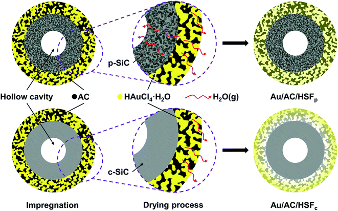
Based on the hollow structure of the novel structured support and the porous properties of the ceramic wall, we speculate that there is an interesting phenomenon in the distribution of active component in the second support during the impregnation and drying of the catalyst. As shown in Fig. 10, HAuCl4 solution was absorbed into the activated carbon layer during the impregnation. Nevertheless, during the drying process, water vapor cannot volatilize through the inner-channel because the wall of the HSFc is compact. Internal moisture can only gradually spread to the outer surface and volatilize, this may lead to a gradient distribution of the catalyst in the radial direction of the activated carbon coating, and there were almost no Au species existing in the side near the SiC. While for the HSFp, the wall is porous so the water vapor can be evaporated bidirectional through the inner-channel and the outer-channel, as shown in Fig. 10. Therefore, all activated carbon coating can be used to provide loading sites for active component. On the premise of the quality of activated carbon, the volume of structured support and the amount of Au species are consistent, the distribution of active component on AC/HSFp will certainly be better. This is reasonable because on the one hand, the HAuCl4 solution was driven by drying to form a concentration gradient on the AC/HSFc activated carbon, the Au species were mainly distributed in the outside of carbon; on the other hand, the high density AuCl3 crystals accumulated on the outer part of the carbon will inevitably aggregate to form large clusters, which can be verified from Fig. 7 and 9.
To further verify the mechanism of this speculation, the Au/AC/HSFc structured catalyst was prepared by freeze-drying method and the distribution of the used catalyst in its cross-section was characterized, and the result is shown in Fig. S8.† It can be found that the distribution of catalyst is equivalent to that of Au/AC/HSFp prepared by the conventional drying in Fig. 9c. The Au/AC/HSFc structured catalyst prepared by the freeze-drying method was tested in the acetylene hydrochlorination and the result is shown in Fig. S9.† Freeze-drying can avoid the migration of moisture and maintain the original distribution of catalyst, which has been reported in the literature.39 However, its cost is very high and cannot be widely used. The HSFp support can achieve the effect of freeze-dried samples, indicating that it has great application value in the field of catalyst preparation. Combining with the other characterization results, the hollow structure of HSF and the presence of pores on ceramic wall play an important role in enhancing the stability of the Au/AC/HSF structured catalyst in acetylene hydrochlorination.
Conclusions
In this study, two novel structured catalysts (Au/AC/HSFc and Au/AC/HSFp) were successfully prepared for acetylene hydrochlorination. XRT shows the 3D interconnected structure of hollow SiC foam and the porous ceramic wall of HSFp. XRD and XPS indicate that the two structured catalysts have similar chemical properties. At an acetylene GHSV of 130 h−1, the reaction time of acetylene conversion above 90% using Au/AC/HSFp is 380 h, which is largely higher than that using the Au/AC/HSFc (200 h). According to the characterization results of SEM and TEM, compared with Au/AC/HSFc, the Au/AC/HSFp has the better active component distribution, which can significantly inhibit the deactivation of the catalyst. This is mainly due to the ability of the bidirectional drying based on the hollow SiC foam with porous ceramic wall. Therefore, this novel HSFp shows a great potential to improve the catalytic performance of structured catalyst for multiphase chemical reactions.Author contributions
Peng Wang and Xiaodan Yang designed and performed experiments and analyzed data. Peng Wang and Ye Zhang wrote and edited the manuscript. Yong Gao provided the original SiC foam material. Jinsong Zhang reviewed and supervised the manuscript. All authors have read and agreed to the published version of the manuscript.Conflicts of interest
There are no conflicts to declare.Acknowledgements
The authors gratefully acknowledge the financial support of the project from the Shenyang National Laboratory for Materials Science (SYNL) Program for Youth Talent (Grant No. L2020F38).References
- Y. Z. Dong, W. Li, Z. Yan and J. L. Zhang, Catal. Sci. Technol., 2016, 6, 7946–7955 RSC.
- B. L. Wang, J. Zhao, Y. X. Yue, G. F. Sheng, H. X. Lai, J. Y. Rui, H. H. He, Z. T. Hu, F. Feng, Q. F. Zhang, L. L. Guo and X. N. Li, ChemCatChem, 2019, 11, 1002–1009 CAS.
- K. Zhou, J. K. Si, J. C. Jia, J. Q. Huang, J. Zhou, G. H. Luo and F. Wei, RSC Adv., 2014, 4, 7766–7769 RSC.
- S. K. Kaiser, R. Lin, S. Mitchell, E. Fako, F. Krumeich, R. Hauert, O. V. Safonova, V. A. Kondratenko, E. V. Kondratenko, S. M. Collins, P. A. Midgley, N. Lopez and J. Perez-Ramirez, Chem. Sci., 2019, 10, 359–369 RSC.
- H. Y. Zhang, B. Dai, W. Li, X. G. Wang, J. L. Zhang, M. Y. Zhu and J. J. Gu, J. Catal., 2014, 316, 141–148 CrossRef CAS.
- X. Y. Li, J. L. Zhang, Y. Han, M. Y. Zhu, S. S. Shang and W. Li, J. Mater. Sci., 2017, 53, 4913–4926 CrossRef.
- X. Y. Qi, W. Li, J. J. Gu, C. L. Guo and J. L. Zhang, RSC Adv., 2016, 6, 105110–105118 RSC.
- G. Malta, S. A. Kondrat, S. J. Freakley, C. J. Davies, L. Lu, S. Dawson, A. Thetford, E. K. Gibson, D. J. Morgan, W. Jones, P. P. Wells, P. Johnston, C. R. A. Catlow, C. J. Kiely and G. J. Hutchings, Science, 2017, 355, 1399–1402 CrossRef CAS PubMed.
- M. Conte, A. F. Carley and G. J. Hutchings, Catal. Lett., 2008, 124, 165–167 CrossRef CAS.
- L. Ye, X. P. Duan, S. Wu, T. S. Wu, Y. X. Zhao, A. W. Robertson, H. L. Chou, J. W. Zheng, T. Ayvali, S. Day, C. Tang, Y. L. Soo, Y. Z. Yuan and S. C. E. Tsang, Nat. Commun., 2019, 10, 914–923 CrossRef PubMed.
- C. F. Huang, M. Y. Zhu, L. H. Kang, X. Y. Li and B. Dai, Chem. Eng. J., 2014, 242, 69–75 CrossRef CAS.
- K. Zhou, J. C. Jia, C. H. Li, H. Xu, J. Zhou, G. H. Luo and F. Wei, Green Chem., 2014, 17, 356–364 RSC.
- B. Wang, Y. Yue, S. Wang, S. Shao, Z. Chen, X. Fang, X. Pang, Z. Pan, J. Zhao and X. Li, Green Energy Environ., 2020, 6, 9–14 CrossRef.
- K. C. O'Connell, J. R. Monnier and J. R. Regalbuto, Appl. Catal., B, 2018, 225, 264–272 CrossRef.
- B. Dai, Q. Wang, F. Yu and M. Zhu, Sci. Rep., 2015, 5, 10553–10562 CrossRef PubMed.
- X. D. Yang, C. H. Jiang, Z. M. Yang and J. S. Zhang, J. Mater. Sci. Technol., 2014, 30, 434–440 CrossRef CAS.
- T. A. Nijhuis, A. E. W. Beers, T. Vergunst, I. Hoek, F. Kapteijn and J. A. Moulijn, Catal. Rev., 2001, 43, 345–380 CrossRef CAS.
- G. Bond, R. B. Moyes, S. D. Pollington and D. A. Whan, Stud. Surf. Sci. Catal., 1993, 75, 1805–1808 CrossRef CAS.
- A. Prause, J. Meissner, R. Schomäcker and G. H. Findenegg, Microporous Mesoporous Mater., 2020, 304, 109136–109143 CrossRef CAS.
- P. A. Simonov, O. V. Cherstiouk, A. N. Kuznetsov, V. I. Zaikovskii, T. Y. Kardash, A. G. Oshchepkov, A. Bonnefont and E. R. Savinova, J. Electroanal. Chem., 2019, 852, 113551–113556 CrossRef CAS.
- L. Meng, H. Z. Guo, Z. Y. Dong, H. Jiang, W. H. Xing and W. Q. Jin, Chem. Eng. J., 2013, 223, 356–363 CrossRef CAS.
- B. F. K. Kingsbury, Z. Wu and K. Li, Catal. Today, 2010, 156, 306–315 CrossRef CAS.
- H. Ahmadi, S. A. Hashemifard and A. F. Ismail, Chem. Eng. Res. Des., 2017, 120, 218–230 CrossRef CAS.
- D. Hao, Z. M. Yang, C. H. Jiang and J. S. Zhang, J. Mater. Sci. Technol., 2013, 29, 1074–1078 CrossRef CAS.
- R. Z. Jiang, Y. L. Jiao, Y. P. Xie, Z. M. Yang and J. S. Zhang, Chem. Eng. Process., 2019, 137, 108–115 CrossRef CAS.
- M. E. Kartal, L. H. Dugdale, J. J. Harrigan, M. A. Siddiq, D. Pokrajac and D. M. Mulvihill, J. Mater. Sci., 2017, 52, 10186–10197 CrossRef CAS.
- K. Li, Y. L. Jiao, Z. M. Yang and J. S. Zhang, J. Mater. Sci. Technol., 2019, 35, 159–167 CrossRef.
- Y. Jia, R. S. Hu, Q. H. Zhou, H. Y. Wang, X. Gao and J. Zhang, J. Catal., 2017, 348, 223–232 CrossRef CAS.
- Y. Yuan, Y. J. Ding, C. H. Wang, F. Xu, Z. S. Lin, Y. Y. Qin, Y. Li, M. L. Yang, X. D. He, Q. Y. Peng and Y. B. Li, ACS Appl. Mater. Interfaces, 2016, 8, 16852–16861 CrossRef CAS PubMed.
- X. X. Di, J. Zhao, Y. Yu, X. L. Xu, S. C. Gu, H. H. He, T. T. Zhang and X. N. Li, Chin. Chem. Lett., 2016, 27, 1567–1571 CrossRef CAS.
- B. Nkosi, M. D. Adams, N. J. Coville and G. J. Hutchings, J. Catal., 1991, 128, 378–386 CrossRef CAS.
- K. Zhou, W. Wang, Z. Zhao, G. H. Luo, J. T. Miller, M. S. Wong and F. Wei, ACS Catal., 2014, 4, 3112–3116 CrossRef CAS.
- Y. F. Pu, J. L. Zhang, X. Wang, H. Y. Zhang, L. Yu, Y. Z. Dong and W. Li, Catal. Sci. Technol., 2014, 4, 4426–4432 RSC.
- J. Zhao, S. Wang, B. Wang, Y. Yue, C. Jin, J. Lu, Z. Fang, X. Pang, F. Feng, L. Guo, Z. Pan and X. Li, Chin. J. Catal., 2021, 42, 334–346 CrossRef CAS.
- X. L. Qiao, Q. X. Guan and W. Li, Sci. Sin.: Chim., 2019, 49, 1–16 CrossRef.
- J. C. Matsubu, S. Zhang, L. DeRita, N. S. Marinkovic, J. G. Chen, G. W. Graham, X. Pan and P. Christopher, Nat. Chem., 2017, 9, 120–127 CrossRef CAS PubMed.
- G. M. Mullen, E. J. Evans, B. C. Siegert, N. R. Miller, B. K. Rosselet, I. Sabzevari, A. Brush, Z. Duan and C. Buddie Mullins, React. Chem. Eng., 2018, 3, 75–85 RSC.
- P. Johnston, N. Carthey and G. J. Hutchings, J. Am. Chem. Soc., 2015, 137, 14548–14557 CrossRef CAS PubMed.
- L. S. Fan, D. G. Cheng, F. Q. Chen and X. L. Zhan, Chin. J. Catal., 2019, 40, 1109–1115 CrossRef CAS.
Footnote |
| † Electronic supplementary information (ESI) available. See DOI: 10.1039/d1ra02533c |
| This journal is © The Royal Society of Chemistry 2021 |

