
 Open Access Article
 This Open Access Article is licensed under a Creative Commons Attribution-Non Commercial 3.0 Unported Licence
A novel and low-cost CuPc@C catalyst derived from the compounds of sunflower straw and copper phthalocyanine pigment for oxygen reduction reaction
Haiman Huang†
a,
Ziwei Lan†a,
Wenjun Lib,
Wenhao Moa,
Lei Zhao *acd and
Jun Zhang*a
*acd and
Jun Zhang*a
aDepartment of Physical Science and Technology, Lingnan Normal University, Zhanjiang, 524048, China. E-mail: leizhaolingnan@163.com; zhangjun@lingnan.edu.cn
bThe Second Research Institute of CAAC, No. 17, South Section 2, 2nd Ring Road, Chengdu, P. R. China
cKey Laboratory of Environmentally Friendly Functional Materials and Devices, Lingnan Normal University, Zhanjiang, 524048, China
dKey Laboratory of Clean Energy Materials Chemistry of Guangdong Higher Education Institutes, Lingnan Normal University, Zhanjiang, 524048, P. R. China
First published on 27th April 2021
Abstract
A series of carbon and phthalocyanine catalysts were prepared with uniform and stretchable sunflower straw biological materials as the carbon source and inexpensive copper phthalocyanine (CuPc) pigment as a nitrogen doping source by a facile high-temperature carbonization method. This kind of biomass carbon material sunflower straw with abundant pore structure and sponge-like expansion and contraction functions can not only be used as a source of porous carbon in biomass carbon materials, but also as a carbon carrier with high specific surface area to provide nanoparticle adhesion sites. When it was immersed in the copper phthalocyanine pigment solution, more active sites could be exposed, so that CuPc particles could be uniformly doped and distributed on the porous carbon material. As a result, thanks to the doping of nitrogen atoms and the improvement of graphitization degree, the composite catalyst treated at 800 °C (CuPc@C-800) exhibits a porous structure with a 38 mV lower on-set potential and a high stability of 87.4% compared to commercial Pt/C (20%) catalyst. These results demonstrate that CuPc@C series composite catalysts have a splendid electrochemical performance in oxygen reduction reaction catalysts, which can start a new direction for later workers to study combining the properties of biomass carbon material and the phthalocyanine series of catalysts.
Introduction
In the past several decades, phthalocyanine series and carbon composed catalysts have been extensively investigated for scientific and commercial applications. This class of electro-catalysts towards the oxygen reduction reaction (ORR) plays a key role in achieving highly efficient fuel cells, which is one of the most promising approaches to convert chemical energy to electrical.1 Currently, platinum-based materials are the most efficient electro-catalysts for the ORR in fuel cells. However, due to high cost and low reserves, Pt catalysts are difficult to be widely used in commercial production.2–4 Therefore, the development of low cost and high-efficient catalysts is urgent for the practical applications of fuel cells.In recent years, the development of new catalytic materials based on green principles and biomimetic have been important designed.5–11 Due to this reason, metal porphyrins12 and metal phthalocyanines13,14 have been widely employed in ORR as biomimetic catalysts.9,11 Compared with porphyrins, phthalocyanines can improve thermal and chemical stability, low cost and more availability.15 Transition metal/nitrogen-doped carbon-based structure (M–N–C) shows good ORR performance, and the transition metals are mainly Fe, Co, Cu and Ni.16–20 Recently, it is reported that researchers have conducted a large number of experimental studies to further develop electrocatalysts with high activity and low-cost stability. Huang et al.21 prepared InFeCo@CNS900 composite catalyst by direct calcining of the crystalline indium–organic framework of InOF-24, in which Fe4C and FeCo nanoparticles were formed in situ and embedded into N/S doped carbon materials, showing hierarchically porous nanosheets with microporous and mesoporous structures. Hierarchically porous MOF composite material can effectively improve the overall catalytic performance through the cooperative configuration of each component, Chai et al.22 designed the catalyst for the preparation of cobalt phosphide nanoparticles-embedded carbon nanotubes and N-doped carbon (CoP–InNC@CNT) by growing Co-based coordination polymer on an indium–organic framework. Wang et al.23 reported a novel and environmentally friendly strategy for the preparation of MOF-derived bimetallic phosphides embedded in a carbonaceous matrix (FeNiP/C). The original bimetal phosphide embedded in the carbonaceous matrix is pyrolyzed at 900 °C (FeNiP/C-900), maintaining the shape of a hollow barrel precursor with a high surface area. Simultaneously, thanks to the synergistic effect of Fe and Ni elements and N-doped carbon materials, the in situ formed FeNiP particles exhibited excellent OER catalytic activity.
Among many transition metals, Cu is the natural choice for the catalysis of ORR.24–26 Many references have combined Cu with carbon materials, oxides or other materials to prepare catalysts with high electrocatalytic activity. Rezaeifard et al. prepared a novel magnetically recoverable phthalocyanine catalyst by mobilization of the Cu(II) phthalocyanine-tetrasulfonic acid tetrasodium complex (CuPcS) on the silica coated magnetic nanoparticles (Fe3O4@SiO2, SMNP) via the amine functionality (ASMNP).11 Li et al. synthesized of a Cu single-atom catalyst with a high Cu content of over 20.9 wt%, made of single atomic Cu anchored into an ultrathin nitrogenated two-dimensional carbon matrix (Cu–N–C), which exhibited better tolerance and long-term stability of methanol/carbon monoxide than commercial Pt/C (20%).27 Cui et al. prepared a Cu SAC by a simple pyrolysis method using phthalocyanine Cu as precursor, which found that the half-wave potential is 30 mV lower than the commercial Pt/C (20%) and Cu SAC could be a promising non-noble ORR catalyst for fuel cell applications.28 Zhang et al. were used carbon-supported copper phthalocyanine tetrasulfonic acid tetrasodium salt (CuTSPc/C) nanoparticles as the target catalyst and systematically studied the effects of the transition metal Cu on the ORR active sites.29 Castro et al. reported the synthesis, characterization and catalytic activity of a new Pc coordination polymer and found that the heterogeneous catalytic systems showed a better performance.30 It can be seen that, compared with the relatively high price of phthalocyanine Co and Fe series catalysts, the catalyst composed of phthalocyanine Cu series and carbon materials has been widely used for its high performance and low cost in oxygen reduction catalysts. Therefore, we attempted to adopt a simple high-temperature carbonization method, using uniform stretchable sunflower straw bio-waste materials as biomass carbon material and copper phthalocyanine pigment as nitrogen doping source to prepare CuPc@C composite catalysts and reveal their electrocatalytic performance.
Herein, for the first time, a series of non-precious metal CuPc@C catalysts for ORR of fuel cells were prepared by a facile high-temperature carbonization method, which used sunflower straw, a biomass carbon material with abundant pores structure and sponge-like expansion and contraction functions, as carbon source and copper phthalocyanine pigment, a low-cost and widely available chemical pigment, as nitrogen doping source. As a result, thanks to the doping of nitrogen atoms and the improvement of graphitization degree, the CuPc@C-800 catalyst exhibits a porous structure with a 38 mV lower on-set potential and a high stability of 87.4% than commercial Pt/C (20%) catalyst. Table 1 shows the comparison of the electrochemical performance of Cu-based catalysts found in this study and other reported work.
Experimental details
Fig. 1 is the physical picture of sunflower straw and schematic illustration of the synthesis of CuPc@C series composite catalysts. When applying pressure to compress the sunflower straw to about 4 cm, it could extend to about 16.5 cm after being put into place for a period of time naturally, and expanded three times, which was similar to the expansion and contraction function of sponge. This is why the carbonized porous carbon also had the function of expansion and contraction, but its ability to shrink and expand was weakened. The collected sunflower straw was dehydrated (sun-dried or air-dried), and then putted into an atmospheric tube furnace to dehydrate treatment by the temperature of 400 °C for 1 hour to obtain porous carbon materials with certain shrinkage. Next, the prepared CuPc solution was injected into the porous carbon materials. When the CuPc solution completely penetrated into the porous carbon and soaked it completely, the previously shrinking porous carbon material would expand, increasing its direct contact area with CuPc solution to expose more active sites. As a result, this could provide the attachment sites of the nanoparticles to the greatest extent, and finally the CuPc particles were uniformly distributed on the porous carbon material. After that, the mixture materials were dried in an oven at 80 °C and then putted into a mini tube furnace. In a nitrogen flow environment, set the temperature to preheat for 1 hour, heat- for 1 hour, and carbonize at 700 °C, 750 °C, 800 °C, 850 °C, and 900 °C for 1 hour to prepare CuPc@C series composite catalysts. And the CuPc@C series composite catalysts were denoted as CuPc@C-700, CuPc@C-750, CuPc@C-800, CuPc@C-850, CuPc@C-900. Finally, the yield of CuPc@C-800 was 56%, which was due to the fact that the CuPc was colloidal, and the water in it affected the yield.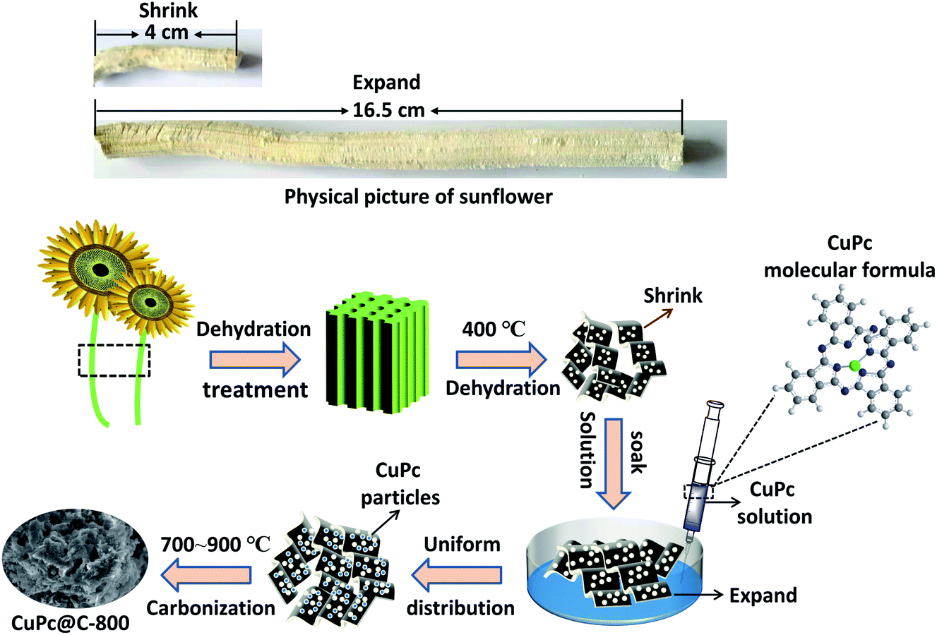 | ||
| Fig. 1 The physical picture of sunflower straw and schematic illustration of the synthesis of CuPc@C series composite catalysts. | ||
The micromorphology, crystallographic information and phase purity, compound structure and chemical composition and elemental valence state of CuPc@C series composite catalysts were recorded by Scanning electron microscopy (SEM, ZEISS Sigma-300), X-ray diffraction (XRD, D/Max 2500/PC), Raman spectroscopy (Renishaw RM-1000) and X-ray Photoelectron Spectroscopy (XPS, ESCALAB 250), respectively.
The electrochemical evaluation was conducted on an electrochemical workstation (RST5200F, Zhengzhou Shiruisi Instrument Co., Ltd. China). Cyclic Voltammetry (CV) and rotating-disk electrode (RDE) polarization curves were measured in a conventional three-electrode system at room temperature. A platinum wire (CHI115) and an Ag/AgCl (sat., CHI111) electrode were used as the counter electrode and reference electrode, respectively. A glassy carbon disk (4 mm in diameter, 0.1256 cm2, Jiangsu Jiangfen Electro-analytical Instrument Co., Ltd.) was used for measuring the different catalysts RDE polarization curves in the potential range from −0.80 to 0 V (vs. Ag/AgCl) in O2-saturated 0.1 M KOH solution at 10 mV s−1 and the RDE polarization curves of CuPc@C-800 catalyst at different rotation rates from 400 to 3600 rpm. Before measurements, GC electrodes were polished with gamma alumina powders (0.05 mm) until a mirror-like surface was obtained, and then washed with double distilled water and dried in vacuum. Subsequently, an appropriate amount of the catalyst (600 μg cm−2) was obtained by mixing the obtained catalysts with ethanol and putting on the GC electrodes. After drying, a drop of Nafion solution (5 wt%, Dupont) was dripped onto the catalyst layer to improve adhesion on the GC surface.31 Before CV or RDE measurement, O2 gas was bubbled into the cell for 30 min to obtain saturated solutions. In order to obtain the influences of the background current, CV and RDE curves were also tested in N2-saturated 0.1 M KOH solution. I–t curves were measured for 15![[thin space (1/6-em)]](https://www.rsc.org/images/entities/char_2009.gif) 000 s at a constant potential of −0.40 V in O2-saturated 0.1 M KOH solution with a flow rate of 20 mL min−1 oxygen at the rotation rate of 1600 rpm.
000 s at a constant potential of −0.40 V in O2-saturated 0.1 M KOH solution with a flow rate of 20 mL min−1 oxygen at the rotation rate of 1600 rpm.
Results and discussion
Fig. 2a and b are SEM images of sunflower straw at low and high magnification after 400 °C treatment, respectively. It can be found that sunflower straw after 400 °C treatment is composed of many nanosheets with different shapes and sizes but uniform thickness (average thickness is about 200 nm), and has high specific surface area. Fig. 2c–h shows SEM images of sunflower straw carbon nanosheets and CuPc particles at different carbonization temperatures (700–900 °C). Compared with Fig. 2d and e, it can be seen that only a small amount of CuPc particles in the CuPc@C catalyst treated at 700 °C (Fig. 2c) are distributed on the surface of the sunflower straw nanosheets carrier, and the degree of recombination is low. With the gradual increase of carbonization temperature, CuPc particles are evenly distributed on the surface of the sunflower straw nanosheets carrier, and the degree of recombination becomes higher and higher (Fig. 2d and e). However, when the carbonization temperature further rises to 850 °C (Fig. 2g), it may be because CuPc particles decompose and cause losses on the surface of the sunflower straw nanosheets carrier, which leads to the failure of CuPc particles and the sunflower straw nanosheets carrier to recombine normally. Further observation in Fig. 2h, it can be found that when the carbonization temperature is finally increased to 900 °C, the CuPc particles and the sunflower straw nanosheets carrier are recombined again. This may be because CuPc particles have been completely decomposed at 900 °C, resulting in the fracture of carbon ring and the formation of some metal particles, which then re-aggregated with the carrier of sunflower straw nanosheets.32 Therefore, the sample (CuPc@C-800) with suitable carbonization temperature is more conducive to the composite of sunflower straw nanosheets carrier and CuPc particles than other CuPc@C series composite. The high-magnification SEM image of CuPc@C-800 in Fig. 2f also further illustrates the distribution and composite degree of CuPc particles and sunflower straw nanosheets carrier. And this good distribution and super high degree of composite benefit from the high specific surface area of the sunflower straw nanosheets, which will generate more active sites, increase the contact area of the catalyst and improve the electrochemical catalytic activity.33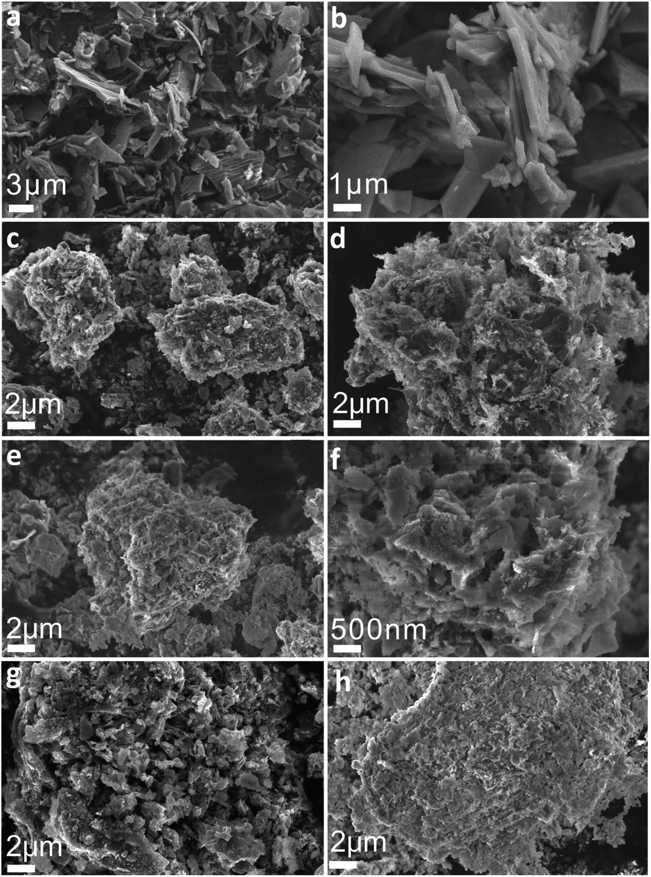 | ||
| Fig. 2 (a) Low magnification (b) high magnification SEM images of sunflower straw after treatment at 400 °C, and SEM images of (c) CuPc@C-700 at low magnification; (d) CuPc@C-750 at low magnification; CuPc@C-800 at (e) low magnification (f) high magnification; (g) CuPc@C-850 at low magnification; (h) CuPc@C-900 at low magnification. | ||
As shown in Fig. 3a, the crystallinity and phase composition of CuPc@C series composite catalysts were further studied by XRD. The XRD pattern of CuPc@C series composite catalysts exhibit two sharp peaks along with several minor peaks at 15.9°, 22.4°, 25.5°, 26.6°, 28.4°, 31.2°, 32.5°, 40.5°, 42.2°, 42.6° and 48.7°, which are assigned to the CuPc. All peaks are matched to CuPc (JCPDS# 06-0007)34 with only slight deviations, but all show high crystallinity. In the XRD pattern of CuPc@C series composite catalysts, a broad peak around 26° can also be clearly seen, which corresponds to the (002) crystal plane of graphite.35 Moreover, it can be found that with the increase of heat treatment temperature, the broad peak of CuPc@C-800 is stronger than CuPc@C-700 and CuPc@C-750, showing a higher degree of graphitization and the structure of sunflower straw biochar has changed into a more ordered form. When the temperature is further increased to 850 °C and 900 °C, the broad peak of CuPc@C-850 becomes weaker, while the broad peak of CuPc@C-900 becomes stronger. Therefore, it can be inferred that the CuPc particles begin to decompose at 850°, and the decomposition has been completed by 900°, accompanied by the fracture of the carbon ring. According to JCPDS, the CuPc@C series composite catalysts also contain SiO2 (JCPDS# 78-1419) impurities,36 which are mainly derived from CuPc pigments. The presence of SiO2 can prevent the precipitation of CuPc pigments and play a role in dispersion, which is more conducive to the composite of sunflower straw carbon nanosheets and CuPc particles.
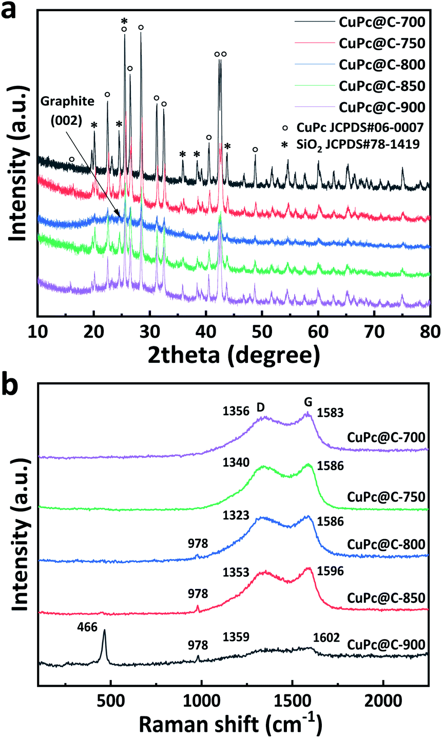 | ||
| Fig. 3 (a) XRD patterns of CuPc@C series composite catalysts, (b) Raman patterns of CuPc@C series composite catalysts. | ||
The compound structure of CuPc@C series composite catalysts were measured by Raman spectroscopy (Fig. 3b). And the Raman peaks observed at 485 cm−1 and 952 cm−1 can be attributed to iso-indole deformation,37,38 while the characteristic D (1340 cm−1) and G (1580 cm−1) bands are composed of amorphous carbon.39,40 From Fig. 3b we can see that, with the increase of carbonization temperature, the catalyst treated at 800 °C (CuPc@C-800) shows a small Raman peak at 978 cm−1, and the Raman peak of CuC@C-850 is larger than that of CuPc@C-800. When the temperature was further raised to 900 °C, it can be found that CuPc@C-900 shows a more obvious Raman peak at 466 cm−1 and 978 cm−1, which indicates that CuPc decomposes and its structure changes under this high temperature treatment. This also proves that the prepared CuPc@C series composite catalysts are successfully mixed with CuPc, and the results are consistent with the XRD pattern. The G band is usually associated with the bond stretching of the sp2 atom pairs of graphene or single crystal graphite, while the D band is attributed to the breathing pattern or defect of the sp2 atom in the rim or other ring of the carbon microcrystalline (within 4 nm).41 As shown in Fig. 3b, all CuPc@C series composite catalysts treated at different temperatures show a G peak greater than 1580 cm−1. The change in the position of the G peak indicates that it has been transferred from nanocrystalline ink to amorphous carbon, thus directly affecting the optical, electrical and mechanical properties of amorphous carbon.42 Table 2 is the statistical table of G-band and D-band intensity values of normalized Raman spectra. Compared with CuC@C-700, CuC@C-750, CuC@C-850 and CuC@C-900, the D-band strength of CuC@C-800 composite catalyst is relatively higher. This can indicate that CuPc@C-800 exhibits higher sp2 cluster evolution, that is, the ordering of amorphous carbon crystallites. The Raman ID/IG ratio calculated from Table 2 (where ID and IG are the Raman intensities of D-band and G-band, respectively) shows that the Raman spectra of CuPc@C-800 has higher ID/IG intensities than those of other catalysts (except CuPc@C-900). The results suggest that CuPc@C-800 increases the graphite domains with rich edges but low disorder,43 which is beneficial to the conduction of electrons and improves the cycle efficiency of the electrode.
| CuPc@C series composite catalysts | CuPc@C-700 | CuPc@C-750 | CuPc@C-800 | CuPc@C-850 | CuPc@C-900 |
|---|---|---|---|---|---|
| ID | 0.89948 | 0.95405 | 0.97352 | 0.94258 | 0.41202 |
| IG | 1 | 1 | 1 | 1 | 0.38778 |
| ID/IG | 0.89948 | 0.95405 | 0.97352 | 0.94258 | 1.06250 |
XPS was conducted to identify the existing elements and valance states of the CuPC@C composite catalysts. XPS survey scan in Fig. 4a shows the whole spectrum including five main elements such as C 1s (ca. 285.84 eV), O 1s (ca. 532.91 eV), N 1s (ca. 400.43 eV), Cu 2p (ca. 933.95 eV and 953.33 eV) and Si (ca. 102.93). To further investigate into the electron states of the CuPc@C series composite catalysts, the XPS fine spectra of C 1s, and Cu 2p N 1s are given in Fig. 4b–d. From the fine spectrum of C 1s (Fig. 4b), it contains two peaks, one at 284.9 eV and another at 286.3 eV, which refer to the aromatic carbon and carbon atoms in the C–N bond,33,44 respectively. As shown in Fig. 4c, the Cu 2p spectrum have two strong peaks, one located at 933.95 eV and another located at 953.33 eV, corresponding to the electron states of Cu 2p3/2 and Cu 2p1/2, indicating the presence of Cu2+ from CuPc.39,44 The binding energy of copper atoms (in Cu 2p3/2 electron state) is 933.95 eV, showing that the copper atoms in CuPc particles is Cu(II).45,46 In the CuPc molecule, the copper atom bonded with nitrogen atoms through coordinate bonds. As shown in the N-doped spectrum in Fig. 4d, the chemical structure of N-doped carbon in carbon is further probed by the fine spectrum. Four components are pyridinic N (398.4 ± 0.2 eV), pyrrolic N (399.9 ± 0.2 eV), quaternary or graphitic N (401.2 ± 0.2 eV), and oxidized N at 402 eV, respectively.47,48 Based on the integrated peak areas, the fractions of each nitrogen components might be quantified. It should be noted that the content of pyridinic and quaternary N dominates 60 atom% in the whole N functionalities. Graphitic and pyridinic nitrogens have been proposed as the key active (Fig. 5) sites for ORR.49 Thus, the further doping of nitrogen makes CuPc@C-800 exhibit excellent electrocatalytic activity for ORR. Moreover, the existence of Cu 2p and N 1s peaks also confirm that CuPC particles have been successfully introduced into all the carbon nanosheets carriers of sunflower straw.50
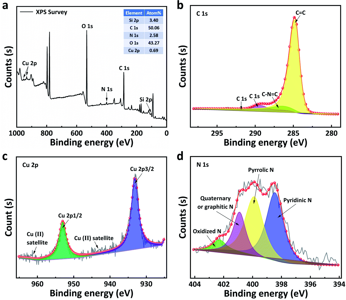 | ||
| Fig. 4 (a) XPS spectrum and the spectrum of (a) C 1s, (c) Cu 2p and (d) N 1s of CuPc@C-800. | ||
In order to identify the properties of CuPc@C series composite catalysts, we compared the results observed from the on-set potential in Fig. 5a. The on-set potential of the CuPc@C-800 is −0.061 V and the commercial Pt/C (20%) catalyst is −0.023 V, which is only 38 mV lower than Pt/C (20%) catalysts. These results demonstrated that CuPc@C series composite catalysts show a close catalyst effect to that of Pt/C (20%) catalysts, except for the limited current density. Fig. 5b are the RDE voltammograms of the CuPc@C-800 at different rotation speeds 400, 900, 1600, 2500, and 3600 rpm, respectively. Similar data were reflected in the curves of Fig. 5c. The derived Koutecky–Levich (K–L) plots in Fig. 5c show the good linearity and parallelism, indicating that the ORR process of the CuPc@C-800 catalyst follows first-order kinetics in the selected potential range from −0.35 to −0.6 V (vs. Ag/AgCl). The electron transfer numbers (n) transferred during ORR and the kinetic limited current density (JK) can be calculated from the following K–L equation:51
 | (1) |
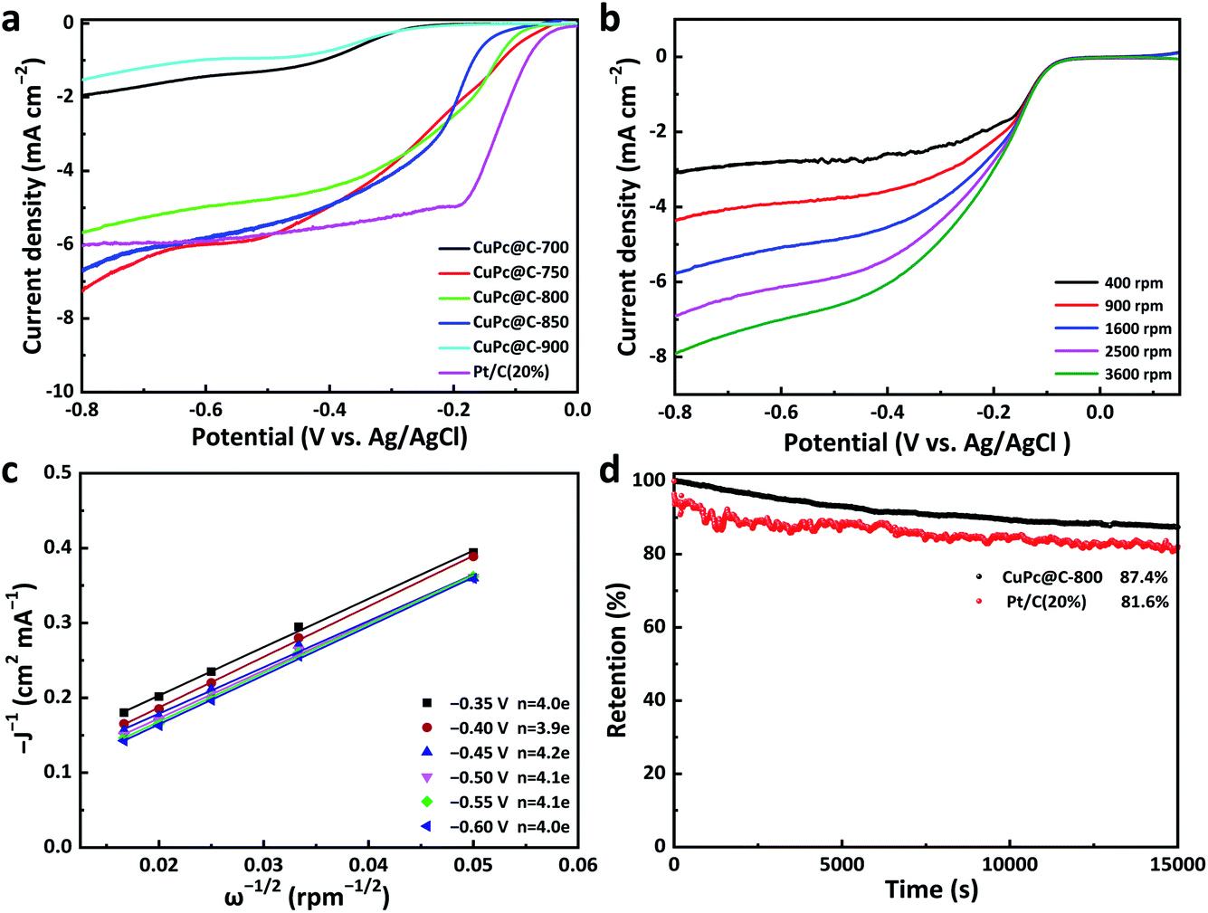 | ||
| Fig. 5 (a) Catalysts polarization curves of CuPc@C and Pt/C (20%) at 1600 rpm at the scan rate of 10 mV s−1, (b) RDE curves for CuPc@C-800 in O2-saturated alkaline solution with the rotation speed of 1600 rpm, (c) different rotation speeds and the corresponding Koutecky–Levich plots (−J−1 vs. ω−1/2) at different electrode potentials in 0.1 M KOH solution, (d) CuPc@C-800 and Pt/C (20%) stability test in O2-saturated 0.1 M KOH solution at −0.40 V (vs. Ag/AgCl) with the rotation speed of 1600 rpm. | ||
The stable testing results of CuPc@C-800 and commercial Pt/C (20%) catalyst were evaluated by I–t curve at a constant potential of −0.4 V in Fig. 5d, all at a disk rotating rate of 1600 rpm. After 15000 s testing, the stability of CuPc@C-800 is up to 87.4%, compared with 81.6% of the commercial Pt/C (20%) catalyst. The relatively higher activity and better durability of CuPc@C-800 is attributed to the co-doping of copper and nitrogen, the increase of graphitization degree and the advantages of the large surface area of porous carbon prepared from sunflower straw.
Conclusions
In summary, a series of CuPc@C composite catalysts with a porous structure were prepared by a facile high-temperature carbonization method, which used sunflower straw, a biomass carbon material with abundant pores structure and sponge-like expansion and contraction functions, as carbon source and copper phthalocyanine pigment, a low-cost and widely available chemical pigment, as nitrogen doping source. As the source of ORR catalysts, the CuPc@C-800 composite catalyst exhibits a 38 mV lower on-set potential and a high stability of 87.4% than commercial Pt/C (20%) catalyst. The high electrocatalytic activity of the CuPc@C-800 composite catalyst can be attributed to the following three points. (1) The porous carbon prepared from sunflower straw, which is a biomass carbon material with abundant pore structure and sponge-like expansion and contraction functions, can provide more attachment sites for CuPc particles when used as a carbon carrier. (2) More active sites are exposed by porous carbon with high specific surface area, which enables CuPc particles to be uniformly distributed on porous carbon and creates a favorable condition for the co-doping of copper and nitrogen. (3) Benefitting from the increase of graphitization degree and the massive formation of pyridinic nitrogen of the CuPc@C composite catalysts, both of them provide more electrocatalytic active sites for ORR. More importantly, the splendid electrochemical performance of CuPc@C series composite catalysts in ORR catalysts would start a new direction for later workers to study the properties of combining biomass carbon materials and phthalocyanine series catalysts.Conflicts of interest
There are no conflicts to declare.Acknowledgements
This work was supported by Zhanjiang Science and Technology Bureau (Grant No. 2019B01002, 2018A02010), Natural Science Foundation of Lingnan Normal University (Grant No. ZL1004, QL1406), Major Projects of Basic and Application Research in Guangdong Province (Grant No. 2017KZDXM055) and Special Fund for Science and Technology Innovation Strategy of Guangdong Province (Grant No. 2018A03015).Notes and references
- A. A. Gewirth, J. A. Varnell and A. M. DiAscro, Chem. Rev., 2018, 118, 2313–2339 CrossRef CAS PubMed.
- Q. Liu, L. Du, G. Fu, Z. Cui, Y. Li, D. Dang, X. Gao, Q. Zheng and J. B. Goodenough, Adv. Energy Mater., 2019, 9, 1803040 CrossRef.
- X. Lu, B. Y. Xia, S. Zang and X. W. D. Lou, Angew. Chem., 2020, 59, 4634–4650 CrossRef CAS PubMed.
- M. P. Browne, Z. Sofer and M. Pumera, Energy Environ. Sci., 2019, 12, 41–58 RSC.
- A. B. Sorokin and A. Tuel, Catal. Today, 2000, 57, 45–59 CrossRef CAS.
- V. B. Sharma, S. L. Jain and B. Sain, Tetrahedron Lett., 2003, 44, 383–386 CrossRef CAS.
- C. Pérollier and A. B. Sorokin, Chem. Commun., 2002, 33, 1548–1549 RSC.
- A. B. Sorokin and A. Tuel, New J. Chem., 1999, 23, 473–476 RSC.
- A. Sorokin and E. Kudrik, Catal. Today, 2011, 159, 37–46 CrossRef CAS.
- M. Alvaro, E. Carbonell, M. Espla and H. Garcia, Appl. Catal., B, 2005, 57, 37–42 CrossRef CAS.
- A. Rezaeifard, M. Jafarpour, A. Naeimi and R. Haddad, Green Chem., 2012, 14, 3386–3394 RSC.
- N. Guillet, L. Roué, S. Marcotte, D. Villers, J. P. Dodelet, N. Chhim and S. T. Vin, J. Appl. Electrochem., 2006, 36, 863–870 CrossRef CAS.
- R. M. Reis, R. S. Rocha and M. R. Lanza, ECS Trans., 2012, 43, 103–109 CrossRef CAS.
- N. Sehlotho and T. Nyokong, J. Electroanal. Chem., 2006, 595, 161–167 CrossRef CAS.
- M. Mahyari, M. S. Laeini and A. Shaabani, Chem. Commun., 2014, 50, 7855–7857 RSC.
- D. Zhang, W. Chen, Z. Li, Y. Chen, L. Zheng, Y. Gong, Q. Li, R. Shen, Y. Han, W. C. Cheong, L. Gu and Y. Li, Chem. Commun., 2018, 54, 4274–4277 RSC.
- G. Wan, C. Yang, W. Zhao, Q. Li, N. Wang, T. Li, H. Zhou, H. Chen and J. Shi, Adv. Mater., 2017, 29, 1703436 CrossRef.
- Y. Cheng, S. Zhao, B. Johannessen, J. P. Veder, M. Saunders, M. R. Rowles, M. Cheng, C. Liu, M. F. Chisholm, R. De Marco, H. M. Cheng, S. Z. Yang and S. P. Jiang, Adv. Mater., 2018, 30, 1706287 CrossRef.
- H. Fei, J. Dong, Y. Feng, C. S. Allen, C. Wan, B. Volosskiy, M. Li, Z. Zhao, Y. Wang, H. Sun, P. An, W. Chen, Z. Guo, C. Lee, D. Chen, I. Shakir, M. Liu, T. Hu, Y. Li, A. I. Kirkland, X. Duan and Y. Huang, Nat. Catal., 2018, 1, 63–72 CrossRef CAS.
- Y. Tu, P. Ren, D. Deng and X. Bao, Nano Energy, 2018, 52, 494–500 CrossRef CAS.
- Q. Huang, Y. Guo, X. Wang, L. Chai, J. Ding, L. Zhong, T.-T. Li, Y. Hu, J. Qian and S. Huang, Nanoscale, 2020, 12, 10019–10025 RSC.
- L. Chai, Z. Hu, X. Wang, Y. Xu, L. Zhang, T.-T. Li, Y. Hu, J. Qian and S. Huang, Adv. Sci., 2020, 7(5), 1903195 CrossRef CAS PubMed.
- X. Wang, L. Chai, J. Ding, L. Zhong, Y. Du, T.-T. Li, Y. Hu, J. Qian and S. Huang, et al., Nano Energy, 2019, 62, 745–753 CrossRef CAS.
- S. B. Ferguson-Miller and G. T. Babcock, Chem. Rev., 1996, 96, 2889–2907 CrossRef CAS PubMed.
- A. Namslauer and P. Brzezinski, FEBS Lett., 2004, 567, 103–110 CrossRef CAS PubMed.
- V. R. I. Kaila, M. I. Verkhovsky and M. Wikström, Chem. Rev., 2010, 110, 7062–7081 CrossRef CAS PubMed.
- L. Feng, G.-F. Han, H.-J. Noh, S.-J. Kim, Y. Lu, H. Y. Jeong, Z. Fu and J.-B. Baek, Energy Environ. Sci., 2018, 11, 2263–2269 RSC.
- L. Cui, Z. Li, J. Zhang, H. Wang, S. Lu and Y. Xiang, J. Mater. Chem. A, 2019, 7, 16690–16695 RSC.
- Q. Zhang, T. Zhu, X. Qing and S. Sun, RSC Adv., 2015, 5, 50344–50352 RSC.
- K. A. Castro, F. Figueira, F. A. A. Almeida Paz, J. P. C. Tomé, R. S. da Silva, S. Nakagaki, M. G. P. M. S. Neves, J. A. S. Cavaleiro and M. M. Q. Simões, Dalton Trans., 2019, 48, 8144–8152 RSC.
- R. M. Reis, R. B. Valim, R. S. Rocha, A. S. Lima, P. S. Castro, M. Bertotti and M. R. V. Lanza, Electrochim. Acta, 2014, 139, 1–6 CrossRef CAS.
- L. Ding, J. Qiao, X. Dai, J. Zhang, J. Zhang and B. Tian, Int. J. Hydrogen Energy, 2012, 37(19), 14103–14113 CrossRef CAS.
- M. Ghasemi, W. R. W. Daud, M. Rahimnejad, M. Rezayi, A. Fatemi, Y. Jafari, M. R. Somalu and A. Manzour, Int. J. Hydrogen Energy, 2013, 38(22), 9533–9540 CrossRef CAS.
- M. Samanta, P. Howli, U. K. Ghorai, M. Mukherjee, C. Bose and K. K. Chattopadhyay, Phys. E, 2019, 114, 113654 CrossRef CAS.
- M. Mukherjee, U. K. Ghorai, M. Samanta, A. Santra, G. P. Das and K. K. Chattopadhyay, Appl. Surf. Sci., 2017, 418, 156–162 CrossRef CAS.
- C. Zhang, Z. Song, H. Shi, J. Fu, Y. Qiao and C. He, BioResources, 2017, 12(1), 1041–1051 CrossRef CAS.
- T. V. Basova, V. G. Kiselev, B.-E. Schuster, H. Peisert and T. Chassé, J. Raman Spectrosc., 2009, 40(12), 2080–2087 CrossRef CAS.
- R. Prabakaran, R. Kesavamoorthy, G. L. N. Reddy and F. P. Xavier, Phys. Status Solidi B, 2002, 229(3), 1175–1186 CrossRef CAS.
- Y. Chen, S. Qu, W. Shi, Q. Yao and L. Chen, Carbon, 2020, 159, 471–477 CrossRef CAS.
- T. T. Guaraldo, L. A. Goulart, F. C. Moraes and M. R. V. Lanza, Appl. Surf. Sci., 2019, 470, 555–564 CrossRef CAS.
- F. C. Vicentini, A. E. Ravanini, L. C. S. Figueiredo-Filho, J. Iniesta, C. E. Banks and O. Fatibello-Filho, Electrochim. Acta, 2015, 157, 125–133 CrossRef CAS.
- A. C. Ferrari and J. Robertson, Phys. Rev. B: Condens. Matter Mater. Phys., 2000, 61(20), 14095 CrossRef CAS.
- K. K. Reddy, M. Satyanarayana, K. Yugender Goud, K. Vengatajalabathy Gobi and H. Kim, Mater. Sci. Eng., C, 2017, 79, 93–99 CrossRef PubMed.
- S. Farahmand, M. Ghiaci and J. S. Razavizadeh, Inorg. Chim. Acta, 2019, 484, 174–179 CrossRef CAS.
- I. I. Vrubel and A. A. Pervishko, JETP Lett., 2020, 111, 293–297 CrossRef CAS.
- Ç. Yağcı and Y. Duman, Biocatal. Biotransform., 2021, 1, 1–9 CrossRef.
- Z. Liu, H. Nie, Z. Yang, J. Zhang, Z. Jin, Y. Lu, Z. Xiao and S. Huang, Nanoscale, 2013, 5, 3283–3288 RSC.
- X. Zhao, J. Zhu, L. Liang, C. Li, C. Liu, J. Liao and W. Xing, Appl. Catal., B, 2014, 154–155, 177–182 CrossRef CAS.
- S. Biniak, G. Szymański, J. Siedlewski and A. Wiatkowski, Carbon, 1997, 35, 1799–1810 CrossRef CAS.
- N. M. Latiff, X. Fu, D. K. Mohamed, A. Veksha, M. Handayani and G. Lisak, Carbon, 2020, 168, 245–253 CrossRef CAS.
- J. Yan, H. Meng, F. Xie, X. Yuan, W. Yu, W. Lin, W. Ouyang and D. Yuan, J. Power Sources, 2014, 245, 772–778 CrossRef CAS.
Footnote |
| † Equal contribution in this paper. |
| This journal is © The Royal Society of Chemistry 2021 |