 Open Access Article
Two dimensional Ni2P/CdS photocatalyst for boosting hydrogen production under visible light irradiation
Li Huanga,
Ruchao Gaoa,
Liuying Xionga,
Perumal Devarajia,
Wei Chen ab,
Xiying Li
 ab and
Liqun Mao
 *ab
*ab
aHenan Engineering Research Center of Resource & Energy Recovery from Waste, Henan University, Kaifeng 475004, PR China. E-mail: mlq@henu.edu.cn; Tel: +86-13513781969
bInstitute of Functional Polymer Composites, College of Chemistry and Chemical Engineering, Henan University, Kaifeng 475004, PR China
First published on 25th March 2021
Abstract
Two-dimensional (2D) semiconductor materials have attracted considerable attention in the field of photocatalysis due to the high interfacial charge separation efficiency and abundant surface active sites. Herein, we have fabricated 2D/2D sheets of Ni2P/CdS heterostructure for photocatalytic H2 evolution. The microscopic and photocatalytic activity results suggested that Ni2P nanosheets were coupled with snowflake CdS. The optimal hydrogen production rate reached 58.33 mmol h−1 g−1 (QE = 34.38%, λ = 420 nm) over 5 wt% Ni2P, which is equivalent to that of 1 wt% Pt/CdS. Compared with pure CdS, Ni2P/CdS presented lower fluorescence intensity and stronger photocurrent density, which demonstrated that the 2D/2D Ni2P/CdS heterojunction photocatalyst significantly improved the separation efficiency of photogenerated electrons and holes. The excellent performance of Ni2P/CdS clearly indicated that Ni2P was an excellent cocatalyst and could provide abundant active sites for hydrogen evolution.
1. Introduction
Since Fujishima et al. reported photocatalytic hydrogen production from water splitting in 1972, increasing attention has been paid in this research field,1 and thus a large amount of photocatalysts have been developed, among which CdS is thought of as a promising photocatalytic semiconductor material with high conductivity and narrow band gap.2 Due to the fast recombination of photo-induced carriers and severe photo-corrosion, CdS alone is inactive,3 and always works with noble metal cocatalysts, such as Pt, Pd, Ru, etc., which has significantly increased the cost of catalysts and thus limits their application.4 Recently, many non-precious metal co-catalysts have been developed,5 such as metal sulfide,6–8 metal carbide,9,10 metal nitride,7,11 metal phosphide12–14 and metallic oxide.15,16 To promote the activity of CdS photocatalysts, our group has tried several strategies, including: (1) Pt-based bi-metal cocatalysts, such as PtPd NPs,17 PtNi NPs,18 and PdNi NPs,19 which can not only reduce the use of precious metals, but also improve the photocatalytic performance because of the synergistic effect of the bimetals; (2) nobel metal free cocatalysts, such as Ni20 or Co,21 also display high photocatalytic activity of H2 generation; (3) structure redesign, such as PtNix polyhedra,22 PtNix hollow structures23 and PtNixCoy concave nanocubes,24 which provide more active sites for photocatalytic H2 generation, and result in the promotion of activity of CdS; (4) dealloying PtNix as a cocatalyst, which shows even higher activity in photocatalytic hydrogen generation.25In this work, a 2D/2D Ni2P/CdS heterostructure was synthesized and used in photocatalytic hydrogen generation from water splitting under visible light. Transition metal phosphates are widely concerned by researchers because of their availability, cheap price and simple preparation method.26 Due to the “ensemble effect” of phosphorus, the binding strength of hydrogen is moderate, which is of great significance for photocatalytic hydrogen production.27 Therefore, 2D structured Ni2P was prepared as the cocatalyst, and modified on the surface of CdS nanosheet to form a novel 2D/2D Ni2P/CdS heterojunction, which shows excellent performance of photocatalytic hydrogen production, and provides a promising prospect for large-scale production of hydrogen in the future.
2. Experimental section
2.1 Reagents and materials
All the chemical reagents, including (NH4)2SO3·H2O were procured from Alfa Aesar Co. Led, China. Cd(CH3COO)2·4H2O and HF were procured from Haohua Chemical Reagent Co. Ltd, China. Ni(CH3COO)2·4H2O, and NH2CSNH2 were ordered from Kermel Chemical Reagent Co. Ltd, China. C2H8N2 was procured from Damao Chemical Reagent Co. Ltd, China. NiCl2·6H2O and red phosphorus were procured from aladdin Chemical Reagent Co. Ltd, China, and used without any further purification.2.2 Synthesis of photocatalysts
2.3 Characterization
XRD patterns were obtained by X-ray diffraction (XRD; Bruker, Germany) with Cu-Kα radiation in 2θ range of 5–90° at a scan rate of 0.3°/s. Scanning electron microscopy (SEM) images were obtained using a JEOL 7610F (Japan). Transmission electron microscopy (TEM) as well as high resolution transmission electron microscopy (HR-TEM) images were collected using a JEM-2010 electron microscope equipped with selected area electron diffraction (SAED). The ultraviolet-visible (UV-vis) diffuse reflectance spectra (DRS) were measured by a UV-vis spectrophotometer UV-2600 (Shimadzu, Japan), The photoluminescence (PL) emission spectra were acquired with a fluorescence spectrophotometer (FLS 980, UK).2.4 Electrochemical measurements
All electrochemical measurements were recorded on a CHI-760 electrochemical system equipped with a standard 3-electrode system and 50 mL of 0.5 M Na2SO4 as electrolyte solution. A glassy carbon electrode (3 mm diameter, 0.07 cm2) was used as the working electrode for Linear sweep voltammetry (LSV), and the modified FTO plates were used as the working electrode for photocurrent spectroscopy test and Mott–Schottky test. A platinum (Pt) wire and a Ag/AgCl were used as the counter and the reference electrodes for all the electrochemical tests, respectively. The measurement of electrochemical impedance spectroscopy (EIS) was conducted at 5 mV AC (alternating current) voltage with a frequency range of 1–105 Hz. A 300 W Xenon lamp with a 420 nm was used as the light source.2.5 Evaluation of photo–catalytic activity
A Teflon-lined stainless steel cylindrical reactor with a circulating water jacket was used as the photoreactor for H2 generation via photocatalytic water splitting. The diameter of the photoreactor is 12.5 cm, and there is a round quartz glass window (with a diameter of 7 cm) on the top center of the photoreactor. A 300 W Xenon lamp was used as the light source with a 420 nm cut-off filter and the measured illumination area of light is approximately 38 cm2. For photocatalytic H2 generation reaction, 0.05 g of CdS photocatalyst and certain amount of Ni2P were added to 50 mL of 1.5 M aqueous (NH4)2SO3·H2O (sacrificial agent) solution. High purity nitrogen was pumped for 30 minutes before photocatalytic activity reaction to obtain an air isolation. Furthermore, the quantum efficiency (QE) of the samples were tested and can be calculated as:3. Results and discussion
3.1 Structure and morphology
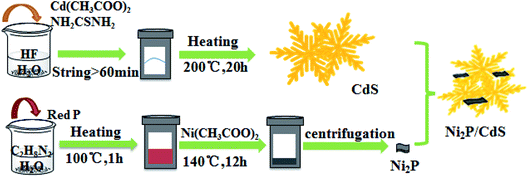
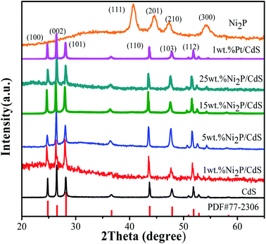
Fig. 2 shows the XRD patterns of CdS, co-catalyst Ni2P, Ni2P/CdS and Pt/CdS photocatalyst. It can be seen that the CdS shows several main diffraction peaks at 24.84°, 26.53°, 28.30°, 43.94° and 47.91°, corresponding to (100), (002), (101), (110) and (103) crystal surfaces, respectively (PDF#77-2306). The main peaks of Ni2P at 40.74°, 44.61°, 47.36°, and 54.20° match well with (111), (201), (210), and (300) planes, respectively, which illustrates that the Ni2P cocatalyst is successfully prepared by the solvothermal method.29As mentioned in the Experimental section, Ni2P or Pt NPs were deposited on the surface of CdS by its photo-induced electrons during the photocatalytic hydrogen generation reaction. After that, Ni2P/CdS or Pt/CdS were separated from the reaction solution, dried at 343 K and the as-obtained powders were used for XRD analysis. As shown in Fig. 2, the XRD patterns of Ni2P/CdS and Pt/CdS are consistent with that of CdS, and no diffraction peak are observed for Ni2P, which may be attributed to the low loading amount of Ni2P.
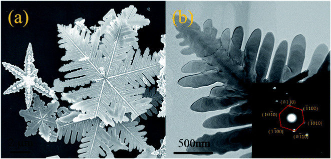
Fig. 3 shows the SEM, TEM and SAED of CdS respectively. As shown Fig. 3(a), the snowflake structure of CdS with a diameter of ∼10 μm was confirmed by both SEM and TEM. Every snowflake structure of CdS has 6 main crystal axes with an angle of 60°, and the secondary crystal axes appear along the main crystal axis, forming many dendrites. The angle between the secondary and primary crystal axes is also 60°. The SAED images (Fig. 3(b), in the inset) of CdS show many bright and highly ordered diffraction pots, which implies the presence of single crystal structure. In the images of calibrated SAED, the six crystal faces corresponding to the inner diffraction points are (01![[1 with combining macron]](https://www.rsc.org/images/entities/char_0031_0304.gif) 0), (
0), (![[1 with combining macron]](https://www.rsc.org/images/entities/char_0031_0304.gif) 100), (
100), (![[1 with combining macron]](https://www.rsc.org/images/entities/char_0031_0304.gif) 010), (0
010), (0![[1 with combining macron]](https://www.rsc.org/images/entities/char_0031_0304.gif) 10), (1
10), (1![[1 with combining macron]](https://www.rsc.org/images/entities/char_0031_0304.gif) 00), (10
00), (10![[1 with combining macron]](https://www.rsc.org/images/entities/char_0031_0304.gif) 0), indicating that the CdS is hexagonal, which is consistent with XRD results. Combined with the XRD test results, it is suggested that HF was adsorbed on the surface (0001) in the hydrothermal reaction process to inhibit the growth of crystals in the vertical direction, leading to the formation of CdS flake structure. The crystals grew rapidly to form the primary crystals, meanwhile the lateral crystals grew out to form a snowflake like structure.
0), indicating that the CdS is hexagonal, which is consistent with XRD results. Combined with the XRD test results, it is suggested that HF was adsorbed on the surface (0001) in the hydrothermal reaction process to inhibit the growth of crystals in the vertical direction, leading to the formation of CdS flake structure. The crystals grew rapidly to form the primary crystals, meanwhile the lateral crystals grew out to form a snowflake like structure.
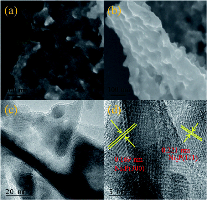
The SEM images (Fig. 4(a) and (b)) show that Ni2P possesses ultrathin nanosheets structure with irregular pores. The HR-TEM images (Fig. 4(c) and (d)) further reveal the subtle nanosheet structure of Ni2P with the crystal plane spacing of 0.221 nm and 0.169 nm, attributed to the (111) and (300) crystal planes, respectively (PDF#74-135).30
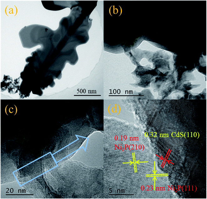
Fig. 5 displays TEM images (Fig. 5(a) and (b)) and the HR-TEM images (Fig. 5(c) and (d)) of Ni2P/CdS, respectively. The interplanar spacing of Ni2P nanosheets was calculated to be 0.22 nm and 0.19 nm, corresponding to its (111) and (210) plane, respectively. In addition, a d-spacing of 0.32 nm was clearly seen and attributed to the (110) plane of CdS.31 Most importantly, the presence of the heterojunction between Ni2P and CdS was confirmed by Fig. 5. The heterointerface generated in Ni2P/CdS will promote the transfer of photogenerated charge carriers to the surface, and inhibit the recombination of photogenerated e−–h+ pairs, result in high the photocatalytic activity.
3.2 Photocatalytic hydrogen generation action
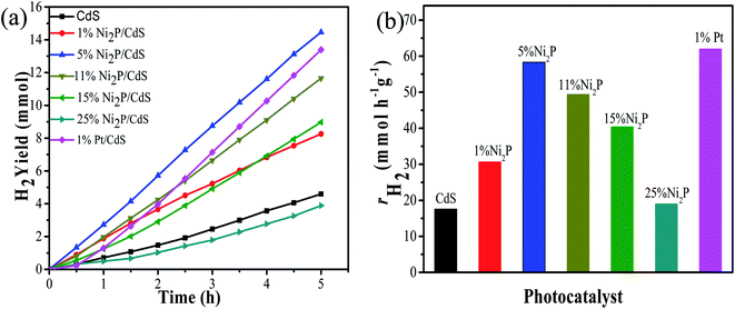
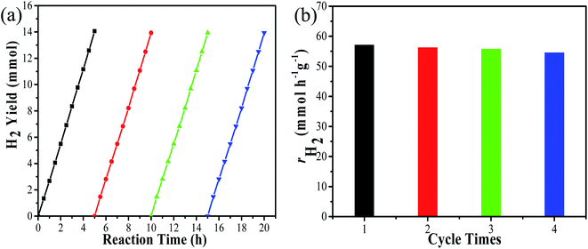
Under visible light irradiation (λ ≥ 420 nm), the photocatalytic H2 evolution of the prepared samples were performed by using 1.5 M as (NH4)2SO3·H2O as the sacrificial reagent. Fig. 6(a) displays H2 evolution performance of Ni2P/CdS photocatalyst with different Ni2P loading contents. CdS alone shows the low activity, probably due to the fast recombination of photogenerated carriers. On the contrary, CdS coupled with Ni2P significantly promoted the hydrogen generation rate. In particular, the highest H2 generation activities reached 58.33 mmol g−1 h−1 (QE = 34.38%, λ = 420 nm) with 5 wt% Ni2P/CdS. However, Ni2P/CdS showed poor photocatalytic activity at low loading amounts of Ni2P, possibly because of less active sites and the heterogeneous junction interface of Ni2P/CdS. When Ni2P loading amounts increased up to 25 wt%, the hydrogen production rate of Ni2P/CdS was lowered than that of pure CdS, because the excess Ni2P nanosheets would affect the light absorption and utilization of CdS. Furthermore, the activity of Ni2P/CdS was also compared with Pt/CdS photocatalyst. In terms of our previous study, the photocatalytic H2 evolution activity of 1wt% Pt/CdS with the best loading amounts was evaluated under the same photocatalytic system.32 As shown in Fig. 6(b), the hydrogen production rate of 5 wt% Ni2P/CdS is colsed to that of 1 wt% Pt/CdS, indicating that Ni2P is an excellent hydrogen evolution co-catalyst and expected to be a desirable substitute for noble metal Pt.In order to investigate the hydrogen production stability of Ni2P/CdS, the 5 wt% Ni2P/CdS catalyst was evaluated for cyclic hydrogen production. At the beginning of each cycle, 2 mL deionized water and 5 g (NH4)2SO3·H2O were used as the supplement. Fig. 7(a) displays the 4 continuous experiments, and the corresponding photocatalytic hydrogen production rate is shown in Fig. 7(b). It can be seen that the hydrogen production activity of 5 wt% Ni2P/CdS is remained basically unchanged after 20 h of cyclic experiments. The four cycle experiments show that hydrogen production rates of 5 wt% Ni2P/CdS are 57.1, 56.2, 55.7 and 54.5 mmol g−1 h−1, respectively, and there is no significant decrease in photocatalytic evolution. The result indicates that 5 wt% Ni2P/CdS catalyst possesses excellent stability under long time light irradiation.
3.3 Spectral properties
Fig. 8(a) shows the UV-visible diffuse reflection spectrum of the as-prepared samples. It can be seen from the graph that the absorption band edge of CdS is located at around 525 nm in the visible light region, indicating that CdS has a good visible light absorption capacity. When Ni2P was modified on the CdS surface, the absorption of Ni2P/CdS photocatalyst enhanced significantly. According to the Tauc plots of CdS and Ni2P shown in Fig. 8(b), the bandgap of CdS and Ni2P were calculated to be 2.41 eV and 1.31 eV, respectively. Combined with Mott–Schottky test results, the energy levels and positions of CdS and Ni2P could be analyzed. As shown in Fig. 8(c and d), the slopes of both curves are positive, which demonstrated that CdS and Ni2P are typical n-type semiconductors. The flat-band potential (Vfb) of CdS and Ni2P are measured to be −0.79 eV and −0.35 eV vs. Ag/AgCl, respectively, and the corresponding standard hydrogen electrodes are −0.59 eV and −0.15 eV (ENHE = EAg/AgCl + 0.2). Based on the literature reports,33 the conduction band (ECB) of n-type semiconductor is very close to the measured Vfb value. In n-type semiconductors, Vfb is 0.1–0.2 eV higher than that of ECB, therefore, ECB of CdS and Ni2P were estimated to be −0.69 eV and −0.25 eV vs. NHE, respectively. According to the formula of EVB = ECB + Eg, the valence band potentials of CdS and Ni2P can be calculated as 1.72 eV and 1.06 eV vs. NHE, respectively, which are basically consistent with the results reported in the literatures.34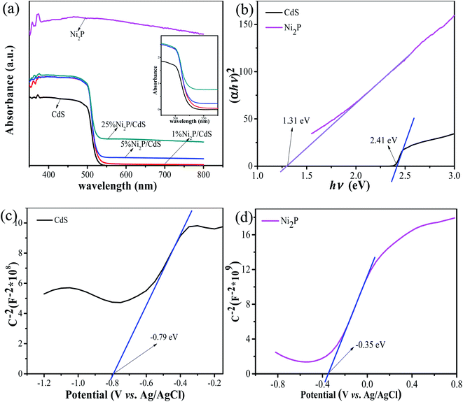 | ||
| Fig. 8 Ultraviolet-visible diffuse reflectance spectra of CdS, Ni2P/CdS photocatalyst (a), Tauc plots of CdS, Ni2P (b), (c) Mott–Schottky plot of CdS and (d) Mott–Schottky plot of Ni2P. | ||
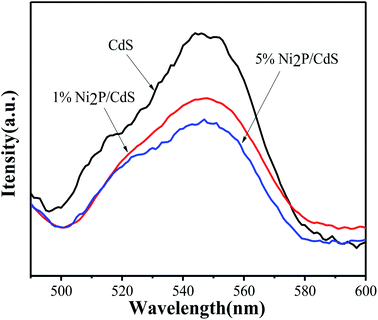
Since the recombination of photogenerated electron–hole pairs in semiconductors can produce fluorescence, the steady PL spectra could be used to evaluate the separation ability of photoelectron–hole pairs.35 It can be seen from the figure that pure CdS shows the highest fluorescence emission characteristics, indicating its highest photogenic carrier recombination rate. When 1 wt% Ni2P was introduced into the system, the emission intensity decreased significantly and fluorescence quenching occurred. Further increase up to 5 wt% Ni2P in photocatalytic system would further weaken the fluorescence intensity. The results show that the 2D/2D heterostructure formed between CdS and Ni2P can greatly promote electron transfer rate and improve the photocatalytic activity (Fig. 9).
3.4 Electrochemical measurements
Fig. 10 displays the LSV curves of CdS, Ni2P/CdS photocatalyst and its corresponding Tafel curves measured in 0.5mol L−1 Na2SO4 electrolyte solution. It can be seen from Fig. 10(a) that Ni2P can significantly improve the hydrogen evolution current density after being modified on the CdS surface, thus showing better hydrogen evolution performance. By comparing with the Tafel curves of CdS, 1 wt% Ni2P/CdS and 5 wt% Ni2P/CdS (Fig. 10(b)), Ni2P nanosheets loaded on CdS shows lower overpotential at any current density. The above results can also be confirmed by transient photocurrent experiments (i–t) under visible light irradiation. As shown in Fig. 10(c), photocurrent is generated immediately at the moment of illumination, indicating that the sample can be illuminated by a xenon lamp to generate photoelectrons, which transferred to the electrode to generate photocurrent. Compared with bare CdS, the photocurrent density of Ni2P/CdS increases significantly, which suggests that the 2D–2D Ni2P/CdS can effectively separate photogenerated electrons and holes to improve the photocatalytic reaction efficiency. Additionally, EIS can evaluate the rate of carrier transport on the semiconductor material surface. As shown in Fig. 10(d), the semicircular diameter is the smallest when Ni2P nanosheets modified on the surface of CdS, which verifies that the 2D/2D Ni2P/CdS heterojunction has the lowest charge transfer resistance and thus shows outstanding performance of photocatalytic H2 production.36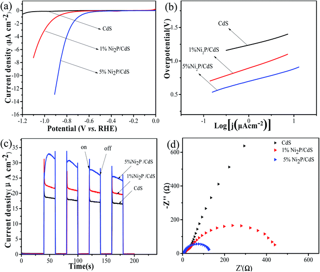 | ||
| Fig. 10 Linear sweep voltammetry (LSV) curves (a), corresponding tafel plots (b), photocurrent–time curves (c) and EIS spectra (d) of CdS, Ni2P/CdS photocatalyst, respectively. | ||
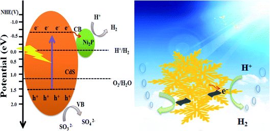
On the basis of the above experimental results and analysis, Fig. 11 proposes the possible mechanism of Ni2P as the co-catalyst supported on CdS surface to promote the photocatalytic activity under visible light irradiation. CdS and Ni2P Mott–Schottky test results show that ECB of CdS and Ni2P is −0.59 eV and −0.15 eV vs. NHE, and EVB is 1.72 eV and 1.06 eV vs. NHE, respectively. Since the ECB of CdS is more negative than that of Ni2P, the photogenerated electrons will be transferred to Ni2P surface across the intimate interface, then reduce H+ to H2. At the same time, the holes on the valence band of CdS are rapidly consumed by the sacrificial reagents. The matching band position of CdS and Ni2P provides an effective and rapid transmission direction for photogenerated electrons and holes, and thus improves the separation efficiency of photogenerated carriers. According to the performance of Ni2P/CdS on photocatalytic H2 production, Ni2P has been demonstrated to behave similar as the noble metal co-catalysts, which can quickly capture electrons, promote separation efficiency of photocatalyst carriers, and improve the efficiency of photocatalytic water splitting. What's more, 2D/2D heterojunction between CdS and Ni2P reduces the transfer distance of photogenerated charge carries to the material surface, which is conducive to the transport and separation of photocatalytic carriers.
4. Conclusion
In this paper, the preparation of 2D/2D structure Ni2P/CdS and hydrogen production have been studied. The results show that the special 2D/2D structure is conducive to the separation of the photogenerated electrons from holes and significantly enhanced the rate of hydrogen evolution. According to the activity data, 5 wt% Ni2P/CdS exhibited the optimal hydrogen production rate of 58.33 mmol h−1 g−1 (QE = 34.38%, λ = 420 nm). The stability test displayed that the activity of 5 wt% Ni2P/CdS decreased by only 4.55% after 4 cycles of photocatalytic H2 evolution, indicating that the synthesized 2D/2D Ni2P/CdS heterojunction has the robust and highly stable performance in the photocatalytic hydrogen production under long time visible light irradiation. SEM and HRTEM characterization showed the micron flake-like single crystal structure of CdS, the nanosheet structure of Ni2P, and the heterojunction formed between the interfaces of Ni2P and CdS. PL and I–T test results showed that 5 wt% Ni2P/CdS displayed lower fluorescence intensity and higher photocurrent density compared with pristine CdS, which suggested that the Ni2P/CdS photocatalyst with 2D/2D structure was more favorable for the separation of photogenerated e−–h+ pairs. Based on the study in this paper, we concluded the reason of high performance H2 production as follows: firstly, as an effective co-catalyst for hydrogen evolution, Ni2P can quickly capture electrons, promote the separation efficiency of photogenerated carriers and photocatalytic performance; secondly, the special 2D/2D contact between CdS and Ni2P is favorable to the transmission of photogenerated electrons and inhibit the recombination of photogenerated carries. In summary, this work displays a possible way to construct 2D/2D heterostructure materials with high photocatalytic performance, which will stimulate tremendous interest in further exploration.Conflicts of interest
Authors have no conflict of interest to declare.Acknowledgements
This work was supported by the Natural Science Foundation of Henan Province (182300410246).References
- A. Fujishima and K. Honda, Nature, 1972, 238, 37–38 CrossRef CAS PubMed.
- L. Cheng, Q. Xiang, Y. Liao and H. Zhang, Energy Environ. Sci., 2018, 11, 1362–1391 RSC.
- D. C. Yong-Jun Yuan, Z.-T. Yu and Z.-G. Zoub, J Mater Chem A, 2013, 6, 11606–11630 RSC.
- X. Zou and Y. Zhang, Chem. Soc. Rev., 2015, 44, 5148–5180 RSC.
- J.-R. Ran, J. Zhang, J.-G. Yu, M. Jaroniec and S.-Z. Qiao, Chem. Soc. Rev., 2014, 43, 7787–7812 RSC.
- J.-T. Zhao, P. Zhang, J. J.-. Fan, J.-H. Hu and G.-S. Shao, Appl. Surf. Sci., 2018, 430, 466–474 CrossRef CAS.
- R. Kumar, D. Das and A. K. Singh, J. Catal., 2018, 359, 143–150 CrossRef CAS.
- K. Zhang, M. Fujitsuka, Y. Du and T. Majima, ACS Appl. Mater. Interfaces, 2018, 10, 20458–20466 CrossRef CAS PubMed.
- Z. Sun, Z. Yu, Y. Liu, C. Shi, M. Zhu and A. Wang, J. Colloid Interface Sci., 2019, 533, 251–258 CrossRef CAS PubMed.
- Y.-Y. Zhao, J. Guo, A.-M. Liu and T.-L. Ma, J. Colloid Interface Sci., 2020, 814, 152271 CAS.
- R. Boppella, J. Tan, W. Yang and J. Moon, Adv. Funct. Mater., 2018, 29, 1807976 CrossRef.
- D. P. Kumar, J. Choi, S. Hong, D. A. Reddy, S. Lee and T.-K. Kim, ACS Sustainable Chem. Eng., 2016, 4, 7158–7166 CrossRef CAS.
- Q.-H. Liang, L.-X. Zhong, C.-F. Du, Y.-B. Luo, J. Zhao, Y. Zheng, J. Xu, J. Ma, C. Liu, S. Li and Q. Yan, ACS Nano, 2019, 13, 7975–7984 CrossRef CAS PubMed.
- Q.-Y. Jian, X.-Q. Hao, Z.-L. Jin and Q.-X. Ma, Phys. Chem. Chem. Phys., 2020, 22, 1932–1943 RSC.
- M. Benamira, N. Doufar and H. Lahmar, Preparation of ZrO2–Fe2O3 Nanoparticles and Their Application as Photocatalyst for Water Depollution and Hydrogen Production, Springer, Singapore, 2021, pp. 11–18 Search PubMed.
- M. Benamira, H. Lahmar, L. Messaadia, G. Rekhila, F. Z. Akika, M. Himrane and M. Trari, Int. J. Hydrogen Energy, 2020, 45, 1719–1728 CrossRef CAS.
- X.-Y. Li, H. Liu, S. Liu, J. Zhang, W. Chen, C.-P. Huang and L.-Q. Mao, Int. J. Hydrogen Energy, 2016, 41, 23015–23021 CrossRef CAS.
- L.-Q. Mao, Q.-Q. Ba, S. Liu, X.-J. Jia, H. Liu, W. Chen and X.-Y. Li, RSC Adv., 2018, 8, 31529–31537 RSC.
- Q.-Q. Ba, X.-J. Jia, L. Huang, X.-Y. Li, W. Chen and L.-Q. Mao, Int. J. Hydrogen Energy, 2019, 44, 5872–5880 CrossRef CAS.
- H. Wang, W. Chen, J. Zhang, C.-H. Huang and L.-Q. Mao, Int. J. Hydrogen Energy, 2015, 40, 340–345 CrossRef CAS.
- W. Chen, Y. Wang, M. Liu, L. Gao, L.-Q. Mao, Z.-Y. Fan and W.-F. Shangguan, Appl. Surf. Sci., 2018, 444, 485–490 CrossRef CAS.
- L.-Q. Mao, Q.-Q. Ba, X.-J. Jia, S. Liu, H. Liu, J. Zhang, X.-Y. Li and W. Chen, RSC Adv., 2019, 9, 1260–1269 RSC.
- Q.-Q. Ba, X.-J. Jia, L. Huang, X.-Y. Li, L. Gao and L.-Q. Mao, Int. J. Hydrogen Energy, 2019, 44, 28104–28112 CrossRef CAS.
- X.-J. Jia, S. Liu, L. Huang, P. Devaraji, L. Walekar, W. Chen, X.-Y. Li, S. Liu and L.-Q. Mao, Catal. Sci. Technol., 2020, 10, 113–123 RSC.
- X.-J. Jia, Q.-Q. Ba, L. Huang, P. Devaraji, W. Chen, X.-Y. Li and L.-Q. Mao, Int. J. Hydrogen Energy, 2019, 44, 26169–26180 CrossRef CAS.
- N. Xiao, S.-S. Li, X.-L. Li, L. Ge, Y.-Q. Gao and N. Li, Chin. J. Catal., 2020, 41, 642–671 CrossRef CAS.
- P. Liu and J. A. Rodriguez, J. Am. Chem. Soc., 2005, 127, 14871–14878 CrossRef CAS PubMed.
- C.-X. Li, L.-J. Han, R.-G. Liu, H.-H. Li, S.-J. Zhang and G.-G. Zhang, J. Mater. Chem., 2012, 22, 23815 RSC.
- E. J. Popczun, J. R. McKone, C. G. Read, A. J. Biacchi, A. M. Wiltrout, N. S. Lewis and R. E. Schaak, J. Am. Chem. Soc., 2013, 135, 9267–9270 CrossRef CAS PubMed.
- T. Liu, A. Li, C.-B. Wang, W. Zhou, S.-J. Liu and L. Guo, Adv. Mater., 2018, 30, e1803590 CrossRef PubMed.
- J.-J. Fang, Y.-K. Chen, W. Wang, L. Fang, C.-H. Lu, C. Zhu, J. Kou, Y. Ni and Z. Xu, Appl. Catal., B, 2019, 258, 117762 CrossRef CAS.
- W. Chen, S. Liu, T.-T. Chu, Q.-Q. Ba, X.-X. Jia and L.-Q. Mao, Chem. Res., 2018, 29, 233–240 Search PubMed.
- M. Bo, J.-P. Zhao, Z.-H. Ge, Y.-Y. Chen and Z.-H. Yuan, Sci. China Mater., 2019, 63, 258–266 Search PubMed.
- H. An, X.-Y. Yan, H. Li, B.-L. Yang, J.-J. Wei and G.-D. Yang, ACS Appl. Energy Mater., 2019, 2, 4195–4204 CrossRef CAS.
- C.-D. Nguyen, V.-H. Nguyen, L. M. T. Pham and T.-Y. Vu, Int J Hydrog Energy, 2020, 45, 15063–15075 CrossRef CAS.
- H.-L. Li, J.-Q. Pan, W.-J. Zhao and C.-R. Li, Appl. Surf. Sci., 2019, 497, 143769 CrossRef CAS.
| This journal is © The Royal Society of Chemistry 2021 |

