 Open Access Article
Sulfur and phosphorus co-doped nickel–cobalt layered double hydroxides for enhancing electrochemical reactivity and supercapacitor performance†
Kyung Su Kima,
Nanasaheb M. Shinde b,
Je Moon Yun
 *bc and
Kwang Ho Kim*ab
aSchool of Materials Science and Engineering, Pusan National University, San 30 Jangjeon-dong, Geumjeong-gu, Busan 609-735, Republic of Korea. E-mail: kwhokim@pusan.ac.kr
bGlobal Frontier R&D Center for Hybrid Interface Materials, Pusan National University, San 30 Jangjeon-dong, Geumjeong-gu, Busan 609-735, Republic of Korea. E-mail: jmyun@deu.ac.kr
cDivision of Advanced Materials Engineering, Dong-Eui University, 176 Eomgwang-ro, Busanjin-gu, Busan, 47340, Republic of Korea
First published on 29th March 2021
Abstract
Layered double hydroxides (LDHs) have drawn significant interest as emerging active materials for advanced energy storage devices; however, their low electric and ionic conductivity limit their applications. In this study, we report sulfur (S) and phosphorus (P) co-doped NiCo LDH nanoarrays prepared via a facile phosphor–sulfurization process to impart diverse co-doping effects. Combining the benefits of their unique hierarchical structure and reduced charge transfer resistance, the S and P co-doped NiCo LDH (NiCo LDH-SP) nanoarrays realize faster and more efficient redox reactions and achieve enhanced surface reactivity, thereby resulting in a performance superior to that of pristine NiCo LDH. Therefore, a NiCo LDH-SP shows an ultra-high specific capacitance of 3844.8 F g−1 at a current density of 3 A g−1 and maintains a specific capacitance of 2538.8 F g−1 at a high current density of 20 A g−1. Additionally, an asymmetric supercapacitor, assembled with the NiCo LDH-SP as the cathode and activated carbon (AC) as the anode (NiCo LDH-SP//AC), shows a high energy density of 74.5 W h kg−1 at a power density of 0.8 kW kg−1 and outstanding cycling stability, thereby retaining ∼81.3% of its initial specific capacitance after 5000 cycles. This study presents a facile and promising strategy for developing LDH-based electrode materials with excellent electrochemical performance for advanced energy storage applications.
1. Introduction
Recently, the global demand for electric engines has increased due to a decrease in the supply of internal combustion engines, and therefore, the importance of energy storage devices has increased.1 Among these devices, supercapacitors have drawn significant interest as promising, next-generation, advanced energy storage devices owing to their high power density, rapid response rate, long life expectancy, and excellent reversibility.2–4Supercapacitors have two classifications according to their charge storage mechanisms, i.e., electric double layer capacitors (EDLCs) and pseudocapacitors. The EDLCs, also known as non-faradaic capacitors, store charge through electrostatic adsorption of ions at the interface of the electrode and electrolyte.5 In contrast, pseudocapacitors store charge through rapid reversible redox reactions and intercalation processes on the electrode surface. Pseudocapacitors have been reported to exhibit greater specific capacitance than EDLCs because of the differences in their charge storage mechanisms. Nevertheless, their relatively low energy densities, compared to those of batteries, still require significant improvement.
Transition-metal oxides/hydroxides have drawn considerable interest owing to their low cost, facile synthesis processes, and intriguing electrochemical properties, which possess multiple oxidation states to accommodate reversible redox reactions.6,7 Among them, layered double hydroxides (LDHs) based on transition metals, especially NiCo LDHs, are considered promising pseudocapacitive materials owing to their tunable composition, high redox reactivity, and outstanding specific capacitance.8–10 LDHs consist of lattices with positively charged brucite-like layers, formed by divalent and trivalent cations, and negatively charged interlayers, formed by anions that electrically compensate for the positively charged layers.11 Although LDHs have a high specific capacitance, their low electronic conductivities limit their practical application by impeding rate performance and cycling stability.12 Therefore, the poor conductivity of LDHs should be improved.
Generally, two methods are used for improving the low electrical conductivity of active materials. One method involves combining the active materials with high-conductivity materials, such as graphene,13 carbon fibers,14 and MXenes,15 whereas the other method involves modifying the structure or composition of the active materials, such as designing core–shell structures,16 introducing electroactive defects,17 and tuning crystallinity.18 The abovementioned mixing processes have been widely used for their simplicity; however, a few studies have reported remarkable increases in the capacitance. In contrast, although the chemical modification or structural alteration processes may be complicated, significant enhancements in electrochemical properties and performances have been achieved using these approaches. Among the various modification methods, recent surface engineering utilizing nonmetallic dopants has been proven effective in enhancing the electrochemical performances of active materials.19–21 This strategy improves the electrical conductivity of active materials and forms additional active sites, with the narrow band gap of transition-metal compounds on their surface, thereby enhancing the performance.22,23 For instance, Xia et al. fabricated surface-modified Co3O4 ultrathin nanosheets through phosphate ion doping. The surface functionalized Co3O4 nanosheets enhanced the redox reactivity and achieved an extremely high capacitance of 1716 F g−1 at a scan rate of 5 mV s−1, whereas the capacitance of pristine Co3O4 nanosheets was 215 F g−1 at the same rate. It confirmed that its lower binding energy could be attributed to the change in surface electronegativity through phosphate ion doping.24 Elshahawy et al. reported that sulfur-doped CoP nanotube arrays demonstrate the superiority of cycling stability and specific capacity that is 1.78 times larger than that of pure CoP nanotube arrays because of the increased number of electrochemically active sites and electrical conductivity by a sulfur-doping effect.25 Yang et al. investigated the edge-site-enriched nanostructures formed by an anion exchange reaction during the introduction of sulfur.26 Density functional theory calculations revealed that enriched edge structures possess a high affinity for the OH− in the electrolyte, thereby resulting in outstanding electrochemical performance due to structural variations. These reports demonstrate that the introduction of nonmetallic dopants improves the electronic conductivity of the active materials. Inspired by these studies, we reasoned that doping active materials with heteroatoms would increase their affinity for the ions involved in electrochemical reactions and enhance the intrinsic conductivity and doping effect. Thus, incorporating both sulfur and phosphorus, i.e., S and P co-doping, is a reasonable approach to designing advanced electrode materials with outstanding electrochemical performances.
In this work, we synthesized NiCo LDHs co-doped with S and P elements via a two-step hydrothermal process. The S and P co-doped NiCo LDH electrode (NiCo LDH-SP) exhibited a superior specific capacitance of 3844.8 F g−1 at 3 A g−1 of a current density compared to 1721 and 2874.3 F g−1 at the same current density, respectively, for the electrodes of a pristine NiCo LDH and a S-doped NiCo LDH (NiCo LDH-S). Moreover, the NiCo LDH-SP showed improved cycling stability after secondary process. These results can be attributed to its hierarchically porous structure and reduced charge transfer resistance obtained through the phosphor–sulfurization process, which enables a fast and efficient faradaic reaction. Further, we determined the conditions that optimizes the co-doping effect of S and P. Among the different dopant concentrations, the NiCo LDH-SP demonstrated the highest specific capacitance and capacitive contribution, indicating that the concentration achieves the fastest redox reaction. Additionally, the resultant NiCo LDH-SP//AC asymmetric supercapacitor (ASC) exhibited an ultra-high energy density of 74.5 W h kg−1 at a power density of 0.8 kW kg−1 and an outstanding retention stability of ∼81.3% after 5000 cycles.
2. Experiments
2.1 Preparation of materials
Analytical grade chemicals, i.e., nickel nitrate hexahydrate (Ni(NO3)2·6H2O, ≥97.0%), cobalt nitrate hexahydrate (Co(NO3)2·6H2O, ≥98.0%), hexamethylenetetramine (HMT, C6H12N4, ≥99.5%), thiourea (CS(NH2)2, ≥99.0%), and sodium hypophosphite monohydrate (NaH2PO2·H2O, ≥99.0%) were used without further purification. All reagents were purchased from Sigma Aldrich. The substrate, Ni foam (2.5 × 4.5 cm2, with a pore density of 110 PPI and a mass density of 320 g m−2), was subjected to sequential ultrasonication in acetone, ethanol, and DI water (15 min each) to remove surface impurities.2.2 Preparation of NiCo LDH
The NiCo LDH materials were synthesized using a facile hydrothermal method. Nickel nitrate hexahydrate (1.5 mmol), cobalt nitrate hexahydrate (1.5 mmol), and HMT (6 mmol) were dissolved in 35 mL DI water; after stirring the solution for ∼30 min, the transparent pink solution was transferred to a 50 mL, Teflon-lined, stainless-steel autoclave containing a piece of Ni-foam substrate (2.5 × 4 cm2). The autoclave was heated and maintained at 120 °C for 12 h. After cooling naturally, the as-synthesized NiCo LDH was rinsed with DI water and then dried at 70 °C for 24 h. The specific mass of the obtained NiCo LDH product is ∼2.2 mg cm−2 (The average weight per unit area in 2.5 cm × 4 cm size, subtracting Ni-foam mass.)2.3 Preparation of S and P co-doped NiCo LDHs
S and P co-doped NiCo LDH products were prepared using CS(NH2)2 (as S source) and NaH2PO2·H2O (as P source) with different feed ratios via a second hydrothermal process. The NiCo LDH-SP with the highest supecapacitive performance was synthesized via the hydrothermal process containing 1 mmol CS(NH2)2, 0.5 mmol NaH2PO2·H2O, and 50 mL DI water (hereafter named NiCo LDH-SP(1)). In detail, the prepared co-doping solution was poured into a 50 mL, Teflon-lined, stainless-steel autoclave containing the un-doped NiCo LDH sample. The autoclave was heated and kept at 120 °C for 3 h. The synthesized NiCo LDH-SP(1) were rinsed with ethanol and de-ionized water several times to remove the residual reactants, and then dried at 70 °C for 24 h. The loading mass of NiCo LDH-SP(1) is ∼3.3 mg cm−2. For other prepared element-doped NiCo LDH samples, all process parameters were unaltered, except for the concentration of doping-source solutions such as 1 mmol CS(NH2)2 (denoted as NiCo LDH-S, ∼3.2 mg cm−2), 1 mmol CS(NH2)2 and 1 mmol NaH2PO2·H2O (denoted as NiCo LDH-SP(2), ∼3.6 mg cm−2), and 1 mmol CS(NH2)2 and 2 mmol NaH2PO2·H2O (denoted as NiCo LDH-SP(3), ∼4.0 mg cm−2), respectively.2.4 Material characterization
The crystal structures were investigated using X-ray diffraction (XRD; Cu Kα radiation, D8 Discover, Bruker). The morphologies and microstructures were characterized by scanning electron microscopy (SEM; 15 kV, S-4800, Hitachi) and transmission electron microscopy (TEM; Talos F200X, Thermo Fisher Scientific) equipped with energy dispersive X-ray spectroscopy. The valence states of the active material were determined by high-performance X-ray photoelectron spectroscopy (XPS; Al-Kα radiation, K-Alpha+, Thermo Fisher Scientific), where the C 1s peak was calibrated to 284.6 eV. The specific surface areas were estimated according to Brunauer–Emmett–Teller (BET) analyses. Barrett–Joyner–Halenda (BJH) analyses were conducted to calculate pore sizes and pore volumes.2.5 Electrochemical characterization
The electrochemical evaluations were performed in a three-electrode system with a 6 M KOH electrolyte solution at room temperature. The synthesized samples were used as working electrodes. Pt foil and Hg/HgO electrodes (WizMAC, South Korea) were used as the counter and reference electrodes, respectively. Cyclic voltammetry (CV), galvanostatic charge–discharge (GCD) measurements, and electrochemical impedance spectroscopy (EIS) were conducted using an electrochemical workstation (ZIVE MP2, WonATech). The EIS analyses were conducted in the frequency range of 100 kHz to 10 mHz under open-circuit potential conditions with an alternate current perturbation of 5 mV.The specific capacitance (Cs, F g−1) or corresponding specific capacity (Qs, C g−1) of the half-cell electrodes was calculated using the following eqn (1):
 | (1) |
 | (2) |
 | (3) |
 | (4) |
 | (5) |
3. Results and discussion
3.1 Structural characterization
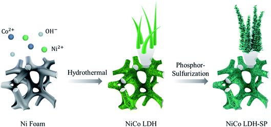
The sulfur- and phosphorus-element co-doped NiCo LDH nanomaterial was successfully synthesized through a two-step hydrothermal process. As shown in Fig. 1, the NiCo LDH nanowires were first grown on the substrate via a first hydrothermal process using HMT as a creating source of hydroxyl anions.27 Then, after a second phosphor-sulfurization hydrothermal process for S and P doping, the pristine NiCo LDH nanowire morphology was converted into S and P co-doped NiCo LDH-SP nanostructure with peeled-off sheets capable of providing increased surface area and enhanced electrochemical performance. The element doping is based on the anion exchange reactions where the OH− sites on the NiCo LDH surface are substituted with S and P species.22,28,29The crystal structures of the as-prepared electrodes were initially examined using XRD analysis; Fig. 2a displays the diffraction patterns of the as-obtained NiCo LDH. The strongest diffraction peaks featuring in all the samples are marked by hollow circles, which correspond to the (111), (200), and (220) planes of the pure Ni as a substrate (JCPDS no. 01-087-0712). Meanwhile, the diffraction pattern of NiCo LDH exhibits the characteristic reflections of the (003), (006), (009), (012), (018), and (110) planes of LDH structures.10,12,30 After S-doping NiCo LDH via a secondary hydrothermal process, the diffraction peaks of NiCo LDH-S appear (marked by stars) at 21.6°, 31.1°, 50.2°, and 54.9°, which correspond to the (101), (110), (511), and (440) planes of the coexistence of the face-centered cubic phase of CoNi2S4 (JCPDS no. 24-0334) and the rhombohedral phase of Ni3S2 (JCPDS no. 44-1418), as shown in Fig. S1.† When doping the S and P elements simultaneously, NiCo LDH-SP(1) shows almost the same pattern with no newly detected peaks or existing peak shifts compared to the NiCo LDH-S. Perhaps, it is considered that P elements did not create a new crystal structure due to the low P content (Table S1†).31 Therefore, there may be some concern as to whether the P is doped into the lattice or is present in the interlayers. When a NiCo LDH-SP(1) sample was measured in XPS and TEM (including EDS) requiring an ultrahigh vacuum pressure of 10−6 to 10−9 Pa, P elements were detected as P 2p XPS spectrum and EDS images as shown in Fig. 2f and 4c, respectively. If P ions are in an intercalated state, the ions may be desorbed on the peeled-off LDH surface and in the interlayer due to the ultrahigh vacuum, making it undetectable. In this regard, it can be assumed that P-element doping occurs predominantly rather than its intercalation between the interfaces.
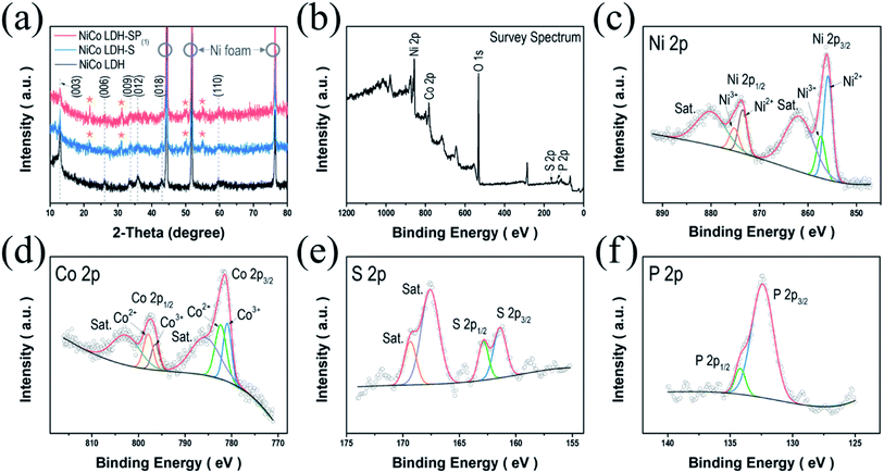 | ||
| Fig. 2 (a) XRD patterns of NiCo LDH, NiCo LDH-S, and NiCo LDH-SP(1). (b) XPS survey spectrum and high-resolution XPS spectra of (c) Ni 2p, (d) Co 2p, (e) S 2p, and (f) P 2p of the NiCo LDH-SP(1). | ||
The valence states of the surface compositions were investigated using XPS analysis. Fig. 2b displays the full survey spectrum of NiCo LDH-SP(1), indicating the coexistence of Ni, Co, P, and S (Table S1†). The Ni 2p spectrum (Fig. 2c) shows two main peaks at 856.1 and 873.7 eV corresponding to Ni 2p3/2 and Ni 2p1/2, respectively, as well as two shake-up satellites (“Sat.”) at 862.0 and 880.2 eV. The deconvoluted peaks at 855.9 and 873.4 eV correspond to Ni2+, while those at 857.4 and 875.3 eV are attributed to Ni3+. In addition, the spin-energy separation of 17.6 eV proves the existence of Ni2+ in NiCo LDH-SP(1).32 The Co 2p spectrum (Fig. 2d) shows two peaks at 782.0 and 797.4 eV consistent with Co 2p3/2 and Co 2p1/2, while the other two peaks can be attributed to two shake-up satellites (“Sat.”). The spin-energy separation of the two main peaks is 15.6 eV, confirming the coexistence of Co2+ and Co3+ in the NiCo LDH-SP(1).33,34 The deconvoluted peaks at 780.9 and 796.4 eV correspond to Co3+, and the peaks at 782.4 and 797.9 eV are attributed Co2+. Fig. 2e shows the S 2p spectrum with two main peaks located at 161.4 and 162.8 eV and two relatively high shake-up satellite (“Sat.”) peaks. The S 2p3/2 (161.4 eV) and S 2p1/2 (162.8 eV) peaks correspond to the metal–sulfur bonding and low coordination surface S2−, respectively.35 In Fig. 2f, the P 2p spectrum shows deconvoluted peaks with P 2p3/2 (132.4 eV) and P 2p1/2 (134.5 eV), corresponding to the positively shifted metal–phosphorus bonding by a more electronegative S ligand and to the P–O bonding, respectively.36,37 The O 1s spectrum in Fig. S2† consists of deconvoluted peaks corresponding to M-OH bonding (at 531.1 eV) and adsorbed water (at 532.4 eV).27,38,39 These results support those obtained through crystal structure analysis, i.e., that S and P co-doping was successfully performed, and indicates that electroactive species exist on the surface of the NiCo LDH-SP(1).
The morphologies and microstructures of NiCo LDH, NiCo LDH-S, and NiCo LDH-SP(1) were examined by SEM (Fig. 3). As shown in Fig. 3a of the low-magnification SEM image, the Ni foam has uniformly covered surfaces with numerous, randomly distributed, NiCo LDH nanowires. A high-magnification SEM image (Fig. 3b) clearly displays that the NiCo LDH nanowires possess a smooth outside and thickness in the range of 50–70 nm. Fig. 3c and d exhibit SEM images of NiCo LDH-S, where NiCo LDH nanowires are anchored with tiny uneven nanosheets, indicating that the sulfurization process produces an open structure without significantly deforming the pristine nanowire morphology of the NiCo LDH. The low-magnification SEM image of NiCo LDH-SP(1) (produced via secondary hydrothermal phosphor–sulfurization) in Fig. 3e shows that NiCo LDH nanowires, decorated with electrochemically active materials, are used as a basis for secondary hydrothermal growth, thereby forming more open and interconnected structures. The high-magnification SEM image (Fig. 3f) shows the NiCo LDH nanowires wrapped in ultrathin (1–5 nm) peeled-off nanosheets, interconnecting to form an open hierarchical structure. Such hierarchically open and interconnected structures increase the specific area and improve ion diffusion and electrolyte penetration, while providing a convenient electron diffusion path.40,41 Hence, the NiCo LDH-SP(1) electrode showed superior electrochemical microstructures and performances, which is discussed in subsequent sections.
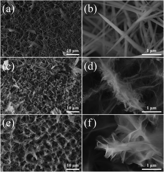 | ||
| Fig. 3 Low- and high-magnification SEM images of (a and b) NiCo LDH, (c and d) NiCo LDH-S, and (e and f) NiCo LDH-SP(1). | ||
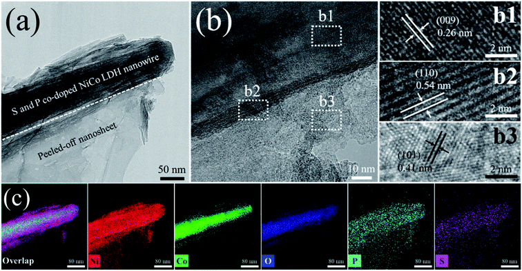
The microstructure and crystalline properties of the NiCo LDH-SP(1) were investigated by transmission electron microscopy (TEM). In Fig. 4a, it is evident that the NiCo LDH-SP(1) is composed of nanowires, which preserve the original shapes of the NiCo LDH, and exfoliated sulfide nanosheets formed by the etching-like effect of S2−, as observed by SEM, thereby realizing an enhanced hierarchical structure. Moreover, a definite, continuous heterointerface, formed from the fringe of nanowires, can be identified between the nanowires and the nanosheets in the HRTEM image in Fig. 4b, which can provide fast channels for charge transfer.42 The HRTEM images in Fig. 4(b1–b3) show clear lattice fringes with interspacings of 0.26, 0.54, and 0.41 nm, corresponding to the (009) plane of NiCo LDH, (110) plane of CoNi2S4, and (101) plane of Ni3S2, respectively. The elemental distributions in Fig. 4c show that Ni, Co, O, P, and S are evenly dispersed in the NiCo LDH-SP(1), which indicates that sulfides are formed by the Kirkendall effect-involved anion exchange reaction during secondary hydrothermal phosphor–sulfurization and that the surface of the NiCo LDH nanowires is uniformly co-doped with S and P species.26
The BET analysis was conducted to estimate specific surface areas and pore distributions of the as-prepared electrodes, as displayed in Fig. S3.† The results of the nitrogen adsorption–desorption isotherms for NiCo LDH and NiCo LDH-SP(1) are summarized in Table S2.† The as-obtained electrodes produce hysteresis loops consistent with a type IV isotherm, indicative of a mesoporous microstructure. The NiCo LDH-SP(1) demonstrates a larger surface area and pore volume than NiCo LDH, which is effective for electrolyte ion/charge storage.43,44 Moreover, it is evident from the inset in Fig. S3† that the phosphor–sulfurization process produced pore sizes less than 40 nm in NiCo LDH-SP(1), while the pore sizes of the NiCo LDH was concentrated at less than 10 nm. This hierarchical structure promotes the infiltration of the electrolyte and diffusion of ions, which is profitable to its supercapacitive properties.45
3.2 Electrochemical performance
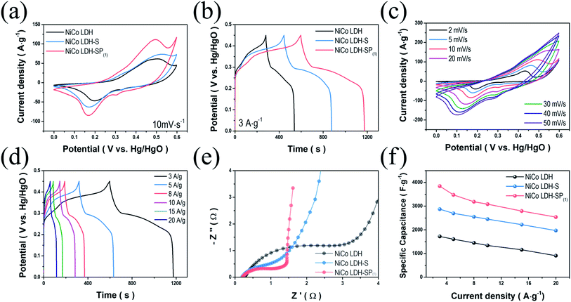
To study the electrochemical behavior of the NiCo LDH, NiCo LDH-S, and NiCo LDH-SP(1), we performed CV measurements over the range of 0–0.6 V. Fig. 5a shows the CV curves of the NiCo LDH, NiCo LDH-S, and NiCo LDH-SP(1) at a scan rate of 10 mV s−1, exhibiting typical pseudocapacitive behaviors with cathodic and anodic peaks at around 0.2 and 0.5 V, respectively. These similar shapes of CV curves can be explained to the faradaic reaction process of the same base active materials according to the following eqn (6)–(8):46| Ni(OH)2 + OH− ↔ NiOOH + H2O + e− | (6) |
| Co(OH)2 + OH− ↔ CoOOH + H2O + e− | (7) |
| CoOOH + OH− ↔ CoO2 + H2O + e− | (8) |
Although the secondary hydrothermal process was performed, there is no change in shape and only peak intensities increase, indicating that functionalized redox reaction by co-doping has a greater effect than the formation of NiCo-sulfides during electrochemical processes. The area enclosed by the CV curve of NiCo LDH-SP(1) is larger than those enclosed by the curves of NiCo LDH and NiCo LDH-S, implying that NiCo LDH-SP(1) has superior electrochemical properties. Hence, S and P species introduced at the surface of NiCo LDH increases the electrochemical activity of surface redox reactions. Moreover, the CV curve-enclosed area of NiCo LDH-SP(1) is larger than those enclosed by CV curves of the NiCo LDH-SP(2) and NiCo LDH-SP(3) electrodes (Fig. S4a†). This confirms that the conditions, under which NiCo LDH-SP(1) is prepared, optimizes the S and P co-doping effect. The supercapacitive performances of NiCo LDH, NiCo LDH-S, and NiCo LDH-SP(1) were evaluated based on GCD measurements in the range of 0–0.45 V at a current density of 3 A g−1. As seen in Fig. 5b, the GCD curves show the typical pseudocapacitive behavior of reversible faradaic reactions. It is obvious that the NiCo LDH-SP(1) demonstrates the longest discharge time, indicating that its supercapacitive performance is enhanced, which is consistent with the trend observed in the CV analysis. Additionally, Fig. S4b† shows that the electrodes with different dopant concentrations exhibit slightly different discharge times, suggesting that the dopant concentration of the NiCo LDH-SP(1) optimizes electrochemical performance, which is consistent with the results of Fig. S4a.† Accordingly, the specific capacitance of NiCo LDH-SP(1) is superior to those of the NiCo LDH-SP(2) and NiCo LDH-SP(3). Fig. 5c shows the CV curves of the NiCo LDH-SP(1) at various scan rates. The characteristics symmetry of redox peaks at lower scan rates indicates that the NiCo LDH-SP(1) possesses an outstanding electrochemical reversibility. As the scan rate increases from 2 to 50 mV s−1, the anodic and cathodic peaks shift toward higher and lower potentials. The reason for this is related mainly to the internal resistance of the electrode. However, the shapes of the CV curves remained relatively unchanged, suggesting that the NiCo LDH-SP(1) possesses a highly reversible faradaic reaction, and is capable of fast ion/electron transport, resulting in a rapid CV response.47 The shapes of the CV curves at different scan rates remain relatively unchanged, suggesting that the NiCo LDH-SP(1) has very high electrical conductivity. The CV curves of other prepared electrodes at various scan rates are shown in Fig. S5.† Fig. 5d shows the GCD curves of NiCo LDH-SP(1) at different current densities from 3 to 20 A g−1. The GCD curves exhibit clear potential plateaus, implying a faradaic reaction involving ions of the electrode. Moreover, the potential variation trend of the GCD curves correspond well with the CV curves in Fig. 5c. Specifically, the potentials at which the GCD curves begin to ascend and descend correspond to the oxidation/reduction peaks in Fig. 5c. The estimated specific capacitances of NiCo LDH-SP(1) are 3844.8, 3476.6, 3186.4, 3083.8, 2792.6, and 2538.8 F g−1 at current densities of 3, 5, 8, 10, 15, and 20 A g−1, respectively. In addition, since the NiCo LDH-SP(1) showed a strong battery-like behavior, it can be expressed as a specific capacity. The estimated specific capacity of NiCo LDH-SP(1) are 1730.2, 1564.5, 1433.9, 1387.7, 1256.7, and 1142.5 C g−1 at current densities of 3, 5, 8, 10, 15, and 20 A g−1. To investigate the conductivity behavior and charge transfer kinetics of the electrodes, EIS analyses were performed. The Nyquist plots (Fig. 5e) of the samples display semi-circles in the high-frequency region and linear sections in the low-frequency region. In the high-frequency region, the intersection with the x-axis represents the internal resistance (Rs) of the cells, involving the electronic resistance of the active materials, the ohmic resistance of the electrolyte, and the contact resistance between the electrode and the current collector. The Rs values of the electrodes differ minimally, ranging from 0.19 to 0.26 Ω. However, the different diameters of the semi-circles (in the high-frequency region) of the plots indicate that the charge transfer resistances (Rct) of the electrodes range between 1.04 and 2.92 Ω. It is apparent that the semi-circle radius of the NiCo LDH-SP(1) plot is smaller than those of the NiCo LDH and NiCo LDH-S plots. This implies that the presence of S and P enhances the electrochemical properties of the electrode by reducing the Rct.48 Moreover, the slope of the linear section of the NiCo LDH-SP(1) plot (in the low-frequency region) has a steeper incline than that of the corresponding sections of the NiCo LDH and NiCo LDH-S plots. This high incline implies ideal capacitive properties with fast ion diffusion in the electrolyte.49 These EIS results demonstrate that the co-doping phosphor–sulfurization process significantly improves the electrical conductivity and charge transfer of the faradaic reaction. Doping processes of nonmetallic elements are a convincing approach for improving the electrochemical properties of active materials. Nonmetallic elements with low electronegativity, such as S and P, increase the fraction of covalent bonds by accommodating the surface charge at the 3p orbitals and vacant 3d orbitals, resulting in weaker electron binding energies in the M2+ and M3+ of the NiCo LDH-SP(1) and longer bonds.24,50 These results confirm that the doping process of nonmetallic elements enhances the supercapacitive performance of active materials by reducing the Rct. As seen in Fig. 5f, the NiCo LDH-SP(1) achieves a higher specific capacitance than the NiCo LDH and NiCo LDH-S. Hence, the electrochemical performance of NiCo LDH-SP(1) is superior to those of the other prepared LDH electrodes.51
The total charge storage mechanism is governed by two processes.5 One is a diffusion-controlled process involving cation intercalation within the active material and ion diffusion in the electrolyte, known as the rechargeable battery mechanism, whereas the other is a capacitive mechanism involving electrochemical adsorption and desorption of ions at the interface of electrode and electrolyte (capacitive behavior) and surface faradaic redox reactions (pseudocapacitive behavior).2 The current contributions of the kinetically different mechanisms can be effectively classified using CV measurements. The current of the electrodes at a constant scan rate is described by the following relationship:15,20
| i = avb | (9) |
| i(V) = k1v + k2v0.5 | (10) |
| i(V)/v0.5 = k1v0.5 + k2 | (11) |
![[thin space (1/6-em)]](https://www.rsc.org/images/entities/char_2009.gif) :
:![[thin space (1/6-em)]](https://www.rsc.org/images/entities/char_2009.gif) 0.5. Therefore, the introduction of S and P onto NiCo LDH increases the surface capacitive contribution to the current enhancing its electrochemical properties.51
0.5. Therefore, the introduction of S and P onto NiCo LDH increases the surface capacitive contribution to the current enhancing its electrochemical properties.51
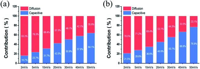 | ||
| Fig. 6 Comparison of the capacitive contribution and diffusion-controlled contribution to current of (a) NiCo LDH and (b) NiCo LDH-SP(1). | ||
The cycling retentions (Fig. S7†) of NiCo LDH and NiCo LDH-SP(1) were evaluated using GCD measurements at a current density of 20 A g−1. The NiCo LDH maintains its initial capacitance of approximately 44.19% after 1500 cycles comparable to the previously reported LDHs.52–54 The capacitance retention of NiCo LDH-SP(1) is slightly higher at approximately 61.01% after 1500 cycles; its improved cycling stability can be ascribed to its low Rct and high electronic conductivity resulting from the co-doping phosphor–sulfurization process.12,55
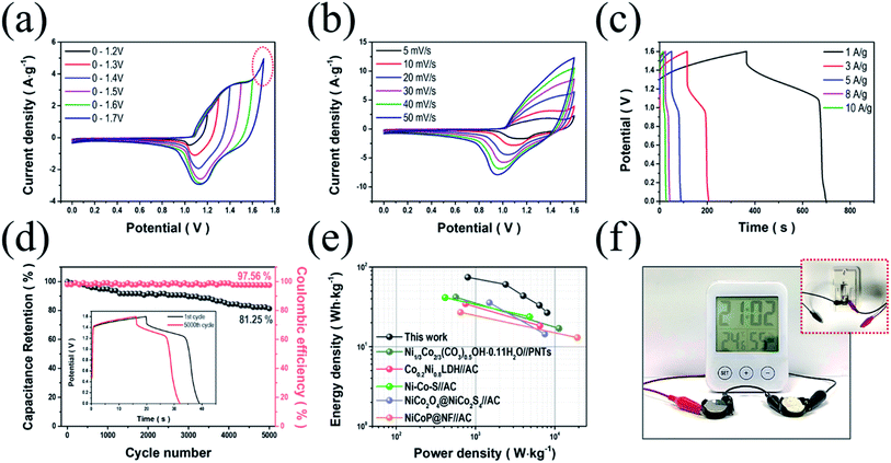
To further investigate the viability of NiCo LDH-SP(1) electrodes in energy storage devices, we fabricated an ASC using NiCo LDH-SP(1) and AC as the cathode and anode (NiCo LDH-SP(1)//AC), respectively. Before assembly, the electrochemical performance evaluation (Fig. S8†) of the AC electrode was performed. The CV curves (Fig. S8a†) of AC electrode exhibit the typical rectangular shapes of EDLCs. The GCD curves (Fig. S8b†) exhibit linear and symmetric shapes, while the EIS curves (Fig. S8c†) show the characteristic of typical EDLCs of a steep line of nearly 90° in the low-frequency. The specific capacitances of the AC electrode are 89.0, 83.5, 80.1, 75.6, and 72.8 F g−1 at current densities of 1, 3, 5, 8, and 10 A g−1, respectively (Fig. S8d†). Fig. 7a shows the CV curves of the assembled ASC device measured at a scan rate of 10 mV s−1, extending the potential range to determine the optimal operating potential window (from 0–1.2 V to 0–1.7 V). The stable CV curves are maintained up to 1.6 V. A sharp increase in current is observed due to polarization, when the range expands to 1.7 V.15 Fig. 7b shows CV curves conducted at scan rates in the potential range of 0–1.6 V, whose shapes manifest a pair of definite peaks, not the ideal rectangular shape. It appears that the pseudocapacitive process dominates the supercapacitive behavior of the ASC, which is attributed to the faradaic reactions of NiCo LDH-SP(1).51,56 Moreover, the CV curves rarely change their shapes even as the scan rate picks up, indicating the good reversibility of the ASC. In Fig. 7c, the GCD curves at various current densities agree well with the CV trends. Furthermore, the specific capacitances of the ASC are estimated as approximately 209.5, 170.3, 122.5, 93, and 75 F g−1 at current densities of 1, 3, 5, 8, and 10 A g−1, respectively. The capacitive contributions of the ASC were estimated based on the CV curves using eqn (9)–(11). Fig. S9† displays the capacitive and diffusion contributions of the ASC; the capacitive contributions are 45.4, 51.2, 59.9, 66.0, 71.0, and 75.3% at scan rates of 5, 10, 20, 30, 40, and 50 mV s−1, respectively. As mentioned, the surface capacitive–controlled process, involving faradaic reactions, dominates charge storage. This also suggests that the NiCo LDH-SP(1)//AC device can be applied as an energy storage device.57 Additionally, the long-term cycling stability (Fig. 7d) of the NiCo LDH-SP(1)//AC was evaluated at 8 A g−1. The ASC retains its initial specific capacitance of approximately 81.3% after 5000 cycles, indicating remarkable cycling stability and practical viability. In addition, the coulombic efficiency was approximately 97.5% after 5000 cycles, demonstrating good reversibility.58,59 Ragone plots of the NiCo LDH-SP(1) based ASC (Fig. 7e) shows that the proposed ASC exhibits a remarkable energy density of 74.5 W h kg−1 at a power density of 0.8 kW kg−1 while maintaining 26.7 W h kg−1 at a power density of 8.0 kW kg−1. Moreover, the NiCo LDH-SP(1)//AC device exhibits better performances than previously reported energy storage devices such as Ni1/3Co2/3(CO3)0.5OH·0.11H2O//PNTs (41.86 W h kg−1 at 11.25 kW kg−1),60 Co0.2Ni0.8LDH//AC (34.5 W h kg−1 at 6.5 kW kg−1),43 NiCo–S//AC (41.4 W h kg−1 at 4.8 kW kg−1),61 NiCo2O4@NiCo2S4//AC (35.6 W h kg−1 at 7.5 kW kg−1),62 and NiCoP@NF//AC (27 W h kg−1 at 19.3 kW kg−1).20 To demonstrate the practical viability of the device, two cells were connected in series and used to operate an LCD digital thermo-hygrometer clock, whose operating voltage is 3 V, for over 5 min (Fig. 7f). This illustrates the high power output and energy storage ability of the NiCo LDH-SP(1)//AC device. These results suggest that the NiCo LDH-SP(1) electrode merits consideration as a promising electrode active material for highly efficient energy storage devices.
4. Conclusion
Herein, hierarchically porous, NiCo LDH-SP(1) nanoarrays were synthesized through a facile two-step hydrothermal process. Surface modification of NiCo LDH involving the introduction of S and P through a phosphor–sulfurization process was successfully performed. The resultant NiCo LDH-SP(1) demonstrated a noticeably higher number of active sites and reduced charge transfer resistance, resulting in enhanced surface reactivity with improved conductivity. Therefore, the NiCo LDH-SP(1) achieved a specific capacitance of 3844.8 F g−1 at a current density of 3 A g−1, which is superior to those of previously reported LDH-based materials. An ASC was fabricated using NiCo LDH-SP(1) and AC as a cathode and anode, respectively. The ASC delivered an ultra-high energy density of 74.5 W h kg−1 at a power density of 0.8 kW kg−1 and retained 26.7 W h kg−1 at a high power density of 8.0 kW kg−1. The proposed ASC also demonstrated outstanding cyclic stability of ∼81.3% after 5000 cycles. This surface modification strategy, i.e., S and P co-doping, may present new opportunities in the fabrication of promising active materials for advanced energy storage devices.Conflicts of interest
There are no conflicts to declare.Acknowledgements
This study was supported by the Global Frontier Program through the Global Frontier Hybrid Interface Materials (GFHIM) of the National Research Foundation of Korea (NRF) funded by the Ministry of Science, ICT & Future Planning (2013M3A6B1078874).References
- W. Raza, F. Ali, N. Raza, Y. Luo, K.-H. Kim, J. Yang, S. Kumar, A. Mehmood and E. E. Kwon, Nano Energy, 2018, 52, 441–473 CrossRef CAS.
- Y. Wang, Y. Song and Y. Xia, Chem. Soc. Rev., 2016, 45, 5925–5950 RSC.
- A. Eftekhari, J. Mater. Chem. A, 2018, 6, 2866–2876 RSC.
- A. Muzaffar, M. B. Ahamed, K. Deshmukh and J. Thirumalai, Renewable Sustainable Energy Rev., 2019, 101, 123–145 CrossRef CAS.
- Y. Shao, M. F. El-Kady, J. Sun, Y. Li, Q. Zhang, M. Zhu, H. Wang, B. Dunn and R. B. Kaner, Chem. Rev., 2018, 118, 9233–9280 CrossRef CAS PubMed.
- J. E. ten Elshof, H. Yuan and P. Gonzalez Rodriguez, Adv. Energy Mater., 2016, 6, 1600355 CrossRef.
- T. F. Yi, T. T. Wei, J. Mei, W. Zhang, Y. Zhu, Y. G. Liu, S. Luo, H. Liu, Y. Lu and Z. Guo, Adv. Sustainable Syst., 2020, 4, 1900137 CrossRef CAS.
- D. S. Hall, D. J. Lockwood, C. Bock and B. R. MacDougall, Proc. R. Soc. A, 2015, 471, 20140792 CrossRef PubMed.
- S. Nishimura, A. Takagaki and K. Ebitani, Green Chem., 2013, 15, 2026–2042 RSC.
- H. Chen, L. Hu, M. Chen, Y. Yan and L. Wu, Adv. Funct. Mater., 2014, 24, 934–942 CrossRef CAS.
- C. Yu, J. Yang, C. Zhao, X. Fan, G. Wang and J. Qiu, Nanoscale, 2014, 6, 3097–3104 RSC.
- J. Chen, X. Wang, J. Wang and P. S. Lee, Adv. Energy Mater., 2016, 6, 1501745 CrossRef.
- W. Wang, N. Zhang, Z. Ye, Z. Hong and M. Zhi, Inorg. Chem. Front., 2019, 6, 407–416 RSC.
- L. Huang, D. Chen, Y. Ding, S. Feng, Z. L. Wang and M. Liu, Nano Lett., 2013, 13, 3135–3139 CrossRef CAS PubMed.
- J. Fu, L. Li, J. M. Yun, D. Lee, B. K. Ryu and K. H. Kim, Chem. Eng. J., 2019, 375, 121939 CrossRef CAS.
- G. Liu, B. Wang, T. Liu, L. Wang, H. Luo, T. Gao, F. Wang, A. Liu and D. Wang, J. Mater. Chem. A, 2018, 6, 1822–1831 RSC.
- H. Liang, H. Jia, T. Lin, Z. Wang, C. Li, S. Chen, J. Qi, J. Cao, W. Fei and J. Feng, J. Colloid Interface Sci., 2019, 554, 59–65 CrossRef CAS PubMed.
- X. Zhao, H.-E. Wang, J. Cao, W. Cai and J. Sui, Chem. Commun., 2017, 53, 10723–10726 RSC.
- B. Liu, D. Kong, J. Zhang, Y. Wang, T. Chen, C. Cheng and H. Y. Yang, J. Mater. Chem. A, 2016, 4, 3287–3296 RSC.
- Y. Lan, H. Zhao, Y. Zong, X. Li, Y. Sun, J. Feng, Y. Wang, X. Zheng and Y. Du, Nanoscale, 2018, 10, 11775–11781 RSC.
- K. Share, A. Westover, M. Li and C. L. Pint, Chem. Eng. Sci., 2016, 154, 3–19 CrossRef CAS.
- J. Li, Z. Liu, Q. Zhang, Y. Cheng, B. Zhao, S. Dai, H.-H. Wu, K. Zhang, D. Ding and Y. Wu, Nano Energy, 2019, 57, 22–33 CrossRef CAS.
- X. Li, A. M. Elshahawy, C. Guan and J. Wang, Small, 2017, 13, 1701530 CrossRef PubMed.
- T. Zhai, L. Wan, S. Sun, Q. Chen, J. Sun, Q. Xia and H. Xia, Adv. Mater., 2017, 29, 1604167 CrossRef PubMed.
- A. M. Elshahawy, C. Guan, X. Li, H. Zhang, Y. Hu, H. Wu, S. J. Pennycook and J. Wang, Nano Energy, 2017, 39, 162–171 CrossRef CAS.
- J. Yang, C. Yu, X. Fan, S. Liang, S. Li, H. Huang, Z. Ling, C. Hao and J. Qiu, Energy Environ. Sci., 2016, 9, 1299–1307 RSC.
- S. Singh, N. M. Shinde, Q. X. Xia, C. V. Gopi, J. M. Yun, R. S. Mane and K. H. Kim, Dalton Trans., 2017, 46, 12876–12883 RSC.
- L. Shen, L. Yu, H. B. Wu, X.-Y. Yu, X. Zhang and X. W. D. Lou, Nat. Commun., 2015, 6, 1–8 Search PubMed.
- Y.-W. Long, H.-Y. Zeng, H.-B. Li, K.-M. Zou, S. Xu and X.-J. Cao, Electrochim. Acta, 2020, 361, 137098 CrossRef CAS.
- J. S. Valente, M. Sánchez-Cantú, E. Lima and F. o. Figueras, Chem. Mater., 2009, 21, 5809–5818 CrossRef CAS.
- Y. T. Liu, L. Tang, J. Dai, J. Yu and B. Ding, Angew. Chem., 2020, 132, 13725–13729 CrossRef.
- X. Wang, X. Li, X. Du, X. Ma, X. Hao, C. Xue, H. Zhu and S. Li, Electroanalysis, 2017, 29, 1286–1293 CrossRef CAS.
- Y. Zhu, C. Huang, C. Li, M. Fan, K. Shu and H. C. Chen, J. Power Sources, 2019, 412, 559–567 CrossRef CAS.
- B. Zhao, L. Zhang, Q. Zhang, D. Chen, Y. Cheng, X. Deng, Y. Chen, R. Murphy, X. Xiong and B. Song, Adv. Energy Mater., 2018, 8, 1702247 CrossRef.
- W. Zou, W. Guo, X. Liu, Y. Luo, Q. Ye, X. Xu and F. Wang, Chem. - Eur. J., 2018, 24, 19309–19316 CrossRef CAS PubMed.
- J. Zhang, R. Cui, X. a. Li, X. Liu and W. Huang, J. Mater. Chem. A, 2017, 5, 23536–23542 RSC.
- E. Manova, C. Severac, A. Andreev and R. Clément, J. Catal., 1997, 169, 503–509 CrossRef CAS.
- K. Li, M. Liu, S. Li, F. Huang, L. Wang and H. Zhang, J. Alloys Compd., 2020, 817, 152712 CrossRef CAS.
- H. Li, Y. Gao, C. Wang and G. Yang, Adv. Energy Mater., 2015, 5, 1401767 CrossRef.
- F. Chen, H. Wang, S. Ji, V. Linkov and R. Wang, Chem. Eng. J., 2018, 345, 48–57 CrossRef CAS.
- C. Wu, J. Cai, Y. Zhu and K. Zhang, RSC Adv., 2016, 6, 63905–63914 RSC.
- D. Chen, M. Lu, L. Li, D. Cai, J. Li, J. Cao and W. Han, J. Mater. Chem. A, 2019, 7, 21759–21765 RSC.
- X. Meng, M. Feng, H. Zhang, Z. Ma and C. Zhang, J. Alloys Compd., 2017, 695, 3522–3529 CrossRef CAS.
- A. Bera, A. K. Das, A. Maitra, R. Bera, S. K. Karan, S. Paria, L. Halder, S. K. Si and B. B. Khatua, Chem. Eng. J., 2018, 343, 44–53 CrossRef CAS.
- F. Deng, L. Yu, G. Cheng, T. Lin, M. Sun, F. Ye and Y. Li, J. Power Sources, 2014, 251, 202–207 CrossRef CAS.
- G. Nagaraju, G. S. R. Raju, Y. H. Ko and J. S. Yu, Nanoscale, 2016, 8, 812–825 RSC.
- P. Sun, W. He, H. Yang, R. Cao, J. Yin, C. Wang and X. Xu, Nanoscale, 2018, 10, 19004–19013 RSC.
- Y. Meng, P. Sun, W. He, B. Teng and X. Xu, Nanoscale, 2019, 11, 688–697 RSC.
- F. Deng, L. Yu, M. Sun, T. Lin, G. Cheng, B. Lan and F. Ye, Electrochim. Acta, 2014, 133, 382–390 CrossRef CAS.
- J. Hao, W. Li, X. Zuo, D. Zheng, X. Liang, Y. Qiang, B. Tan, B. Xiang and X. Zou, J. Alloys Compd., 2018, 768, 57–64 CrossRef CAS.
- B. Li, P. Gu, Y. Feng, G. Zhang, K. Huang, H. Xue and H. Pang, Adv. Funct. Mater., 2017, 27, 1605784 CrossRef.
- H. Xing, Y. Lan, Y. Zong, Y. Sun, X. Zhu, X. Li and X. Zheng, Inorg. Chem. Commun., 2019, 101, 125–129 CrossRef CAS.
- X. Cai, X. Shen, L. Ma, Z. Ji, C. Xu and A. Yuan, Chem. Eng. J., 2015, 268, 251–259 CrossRef CAS.
- F. Lai, Y. Huang, Y.-E. Miao and T. Liu, Electrochim. Acta, 2015, 174, 456–463 CrossRef CAS.
- K. Xiang, J. Guo, J. Xu, T. Qu, Y. Zhang, S. Chen, P. Hao, M. Li, M. Xie and X. Guo, ACS Appl. Energy Mater., 2018, 1, 4040–4049 CrossRef CAS.
- T. Peng, H. Yi, P. Sun, Y. Jing, R. Wang, H. Wang and X. Wang, J. Mater. Chem. A, 2016, 4, 8888–8897 RSC.
- Z. Wang, H. Su, F. Liu, X. Chu, C. Yan, B. Gu, H. Huang, T. Yang, N. Chen and Y. Han, Electrochim. Acta, 2019, 307, 302–309 CrossRef CAS.
- W. G. Pell and B. E. Conway, J. Power Sources, 2004, 136, 334–345 CrossRef CAS.
- C. Peng, S. Zhang, X. Zhou and G. Z. Chen, Energy Environ. Sci., 2010, 3, 1499–1502 RSC.
- Y. Wang, Y. Chen, Y. Liu, W. Liu, P. Zhao, Y. Li, Y. Dong, H. Wang and J. Yang, Electrochim. Acta, 2019, 295, 989–996 CrossRef CAS.
- X. Li, Q. Li, Y. Wu, M. Rui and H. Zeng, ACS Appl. Mater. Interfaces, 2015, 7, 19316–19323 CrossRef CAS PubMed.
- H. Rong, T. Chen, R. Shi, Y. Zhang and Z. Wang, ACS Omega, 2018, 3, 5634–5642 CrossRef CAS PubMed.
Footnote |
| † Electronic supplementary information (ESI) available. See DOI: 10.1039/d1ra00424g |
| This journal is © The Royal Society of Chemistry 2021 |

